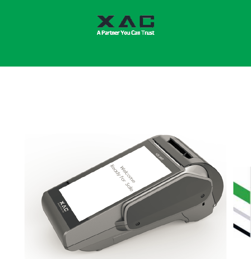
XAC Automation XCE200T3G Terminal User Manual
XAC Automation Corporation Terminal
User Manual

94m
SECURE CLOUD POS TERMINAL
INSTALLATION GUIDE
MODEL:
xCE-200T.3G
xCE_E200T.3G

1. Before Starting
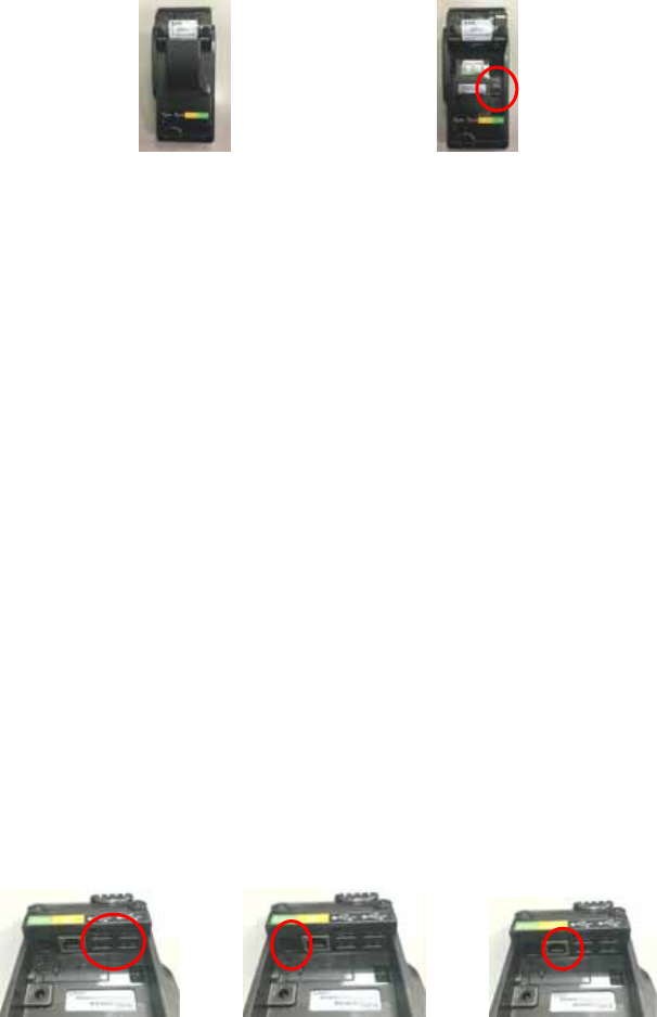
Open the gate behind the device (Figure 1), and find the power input on the right side of the terminal
(Figure 2). Connect the plug from the power adapter into the power input. Plug the power adapter into a
surge suppressor (recommended) after the power cord is connected to the power adapter.
Figure 1 Figure 2
Operating Temperature: 0 °C to 40 °C
Adapter: Chicony Power Technology ,A12-040N1A, I/P: 100-240Vac, 50-60Hz, 1.0A, O/P: 12Vdc,
3.33A
Adapter: 12Vdc, 3.33A(Output rating)
(Use only the XAC Automation Corporation provided AC adapter approved for use with this
device. Use of another AC adapter may cause a fire or explosion)
(This product should only be used with a NRTL approved power supply marked “I.T.E. LPS”
with an output rated 12V DC, minimum 3.0 A, Tma: minimum 40 degree C.)
Caution: The cover (Figure 1) shall be provided with a means to keep it closed during normal operation.
Caution: Risk of explosion if the battery is replaced by an incorrect type. Please dispose of used battery
according to the instructions.
Warning: A shielded-type power cord is required in order to meet FCC emission limits and also to prevent
interference to the nearby radio and television reception. It is essential that only the supplied power cord be
used.
This terminal supports four USB ports and all USB ports located on the back of the terminal. If the terminal
uses a peripheral device with USB connector, plug it into the USB host port (Figure 3).
This terminal supports one RS-232 ports of RJ-12 offset keyed connector. If the terminal uses a peripheral
device with this connector and interface type, plug it into the RS-232 port on the back of the terminal
(Figure 4).
If the terminal needs communication through Ethernet, plug cable into the RJ-45 port on the back of the
terminal (Figure 5).
This terminal supports one micro USB port. You can use micro USB port to connect to other devices and
update your operating system or firmware (Figure 6).
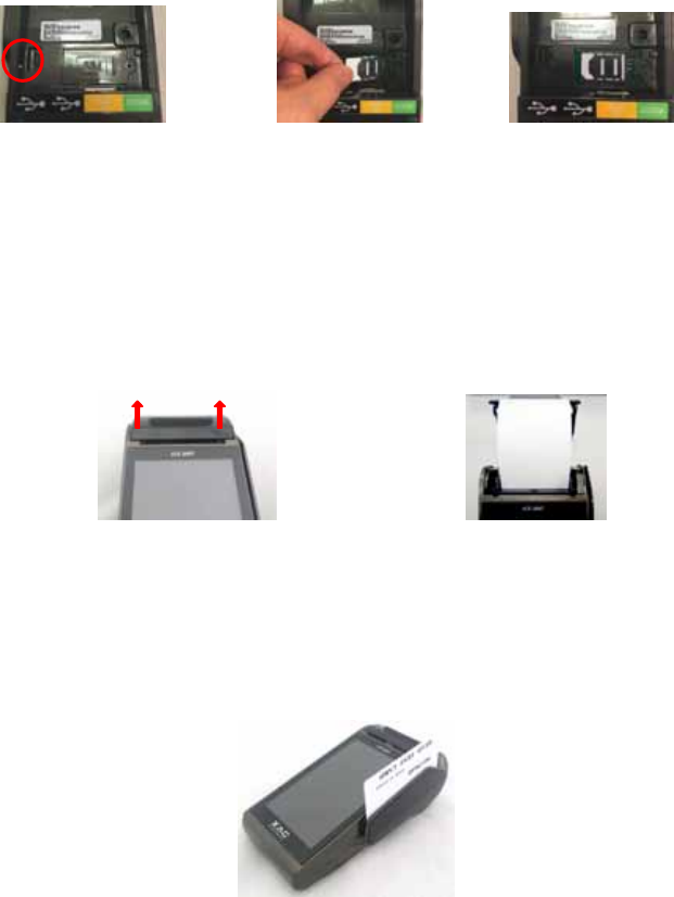
The terminal supports GSM/3G wireless communication and the SIM card slot locates on the bottom of the
device , loose the screw and open the SIM cover, insert the SIM card into SIM card slot to communicate
with GSM/3G, Make sure SIM card is inserted in the right direction. (Figure 7, 8).

Figure 3 Figure 4 Figure5
Figure 6 Figure 7 Figure 8
2. Power On The Terminal
Plug the power cord into the power jack and plug the power adapter into a surge suppressor (recommended)
and the device will boot on simultaneously.
3. Load The Paper
Gently pop the printer cover’s latch to open the cover (Figure 9); then lift the cover. Load a roll of thermal
paper (Appleton 1012 recommended) into the printer (Figure 10). Load it so that the print-side of the paper
will feed out facing the operator. Close the cover by pressing down evenly on both side tabs, or by pressing
on the center of the printer cover. Use the serrated bar to tear off any excess paper.
Figure 9 Figure 10
4. Using The Magnetic Card Reader
Secure Magnetic Card Reader
Find the card reader slot at the right side of terminal. Slide the card in either direction through the slot
without stopping. If the card swipe fails, check the position of the magnetic stripe and slide the card again
(Figure 11).
Figure 11
Caution: Risk of explosion if the battery is replaced by an incorrect type. Please dispose of used battery
according to the instructions.
Warning: This is a Class A product. In a domestic environment this product may cause radio interference in
which case the user may be required to take adequate measures.
Caution: Use only shielded signal cables to connect I/O devices to this equipment. You are cautioned that
changes or modifications not expressly approved by the party responsible for compliance could void your
authority to operate the equipment.

This device complies with Part 15 of the FCC Rules. Operation is subject to the following two conditions: (1)
This device may not cause harmful interference, and (2) this device must accept any interference received,
including interference that may cause undesired operation.
Federal Communication Commission Interference Statement
This equipment has been tested and found to comply with the limits for a Class A digital device, pursuant to part
15 of the FCC Rules. These limits are designed to pro-vide reasonable protection against harmful interference
when the equipment is operate din a commercial environment. This equipment generates, uses, and can radiate
radio frequency energy and, if not installed and used in accordance with the instruction manual, may cause
harmful interference to radio communications. Operation of this equipment in a residential area is likely to cause
harmful interference in which case the user will be required to correct the interference at his own expense.
FCC Caution: Any changes or modifications not expressly approved by the party responsible for compliance
could void the user's authority to operate this equipment.
IMPORTANT NOTE:
FCC Radiation Exposure Statement:
This equipment complies with FCC radiation exposure limits set forth for an uncontrolled environment. This
equipment should be installed and operated with minimum distance 20cm between the radiator & your body.
The above information is the exclusive intellectual property of XAC Automation Corporation and shall not be disclosed,
distributed or reproduced without permission of XAC Automation Corporation.
XAC AUTOMATION CORP. shall not be held liable for technical and editorial omissions or errors made herein; nor
for incidental or consequential damages resulting from the furnishing, performance or use of his material.
This document contains
p
ro
p
rietar
y
information
p
rotected b
y
co
py
ri
g
ht. All ri
g
hts are reserve.
XAC Automation Corporation
886-3-577-2738