Xantrex Dr1512E Users Manual 975 0012 01 02 Rev A
DR2424E to the manual 346bb794-20d8-44d4-b944-476b56c817f9
2015-02-03
: Xantrex Xantrex-Dr1512E-Users-Manual-473638 xantrex-dr1512e-users-manual-473638 xantrex pdf
Open the PDF directly: View PDF ![]() .
.
Page Count: 122 [warning: Documents this large are best viewed by clicking the View PDF Link!]
DR Inverter/Charger
DR1512
DR2412
DR1524
DR2424
DR3624
DR1512W
DR1524W
DR1512E
DR1524E
DR1548E
DR2424E
Installation and Operations Manual

DR Inverter/Charger
Installation and Operation Manual
About Xantrex
Xantrex Technology Inc. is a world-leading supplier of advanced power electronics and controls with products from
50 watt mobile units to one MW utility-scale systems for wind, solar, batteries, fuel cells, microturbines, and backup
power applications in both grid-connected and stand-alone systems. Xantrex products include inverters, battery
chargers, programmable power supplies, and variable speed drives that convert, supply, control, clean, and distribute
electrical power.
Trademarks
DR Inverter/Charger is a trademark of Xantrex International. Xantrex is a registered trademark of Xantrex
International.
Other trademarks, registered trademarks, and product names are the property of their respective owners and are used
herein for identification purposes only.
Notice of Copyright
DR Inverter/Charger Installation and Operations Manual © March 2005 Xantrex International. All rights reserved.
Disclaimer
UNLESS SPECIFICALLY AGREED TO IN WRITING, XANTREX TECHNOLOGY INC. (“XANTREX”)
(a) MAKES NO WARRANTY AS TO THE ACCURACY, SUFFICIENCY OR SUITABILITY OF ANY
TECHNICAL OR OTHER INFORMATION PROVIDED IN ITS MANUALS OR OTHER DOCUMENTATION.
(b) ASSUMES NO RESPONSIBILITY OR LIABILITY FOR LOSS OR DAMAGE, WHETHER DIRECT,
INDIRECT, CONSEQUENTIAL OR INCIDENTAL, WHICH MIGHT ARISE OUT OF THE USE OF SUCH
INFORMATION. THE USE OF ANY SUCH INFORMATION WILL BE ENTIRELY AT THE USER’S RISK.
Date and Revision
March 2005 Revision
Part Number
975-0012-01-02 Rev A
Contact Information
Telephone: 1 800 670 0707 (toll free North America)
1 360 925 5097 (direct)
Fax: 1 800 994 7828 (toll free North America)
1 360 925 5143 (direct)
Email: customerservice@xantrex.com
Web: www.xantrex.com

975-0012-01-02 Rev A iii
About This Manual
Purpose
The purpose of this Installation and Operation Manual is to provide explanations
and procedures for installing, operating, maintaining, and troubleshooting the DR
Inverter/Charger.
Scope
The Manual provides safety guidelines, detailed planning and setup information,
procedures for installing the inverter, as well as information about operating and
troubleshooting the unit. It does not provide details about particular brands of
batteries. You need to consult individual battery manufacturers for this
information.
Audience
The Manual is intended for anyone who needs to install and operate the DR
Inverter/Charger. Installers should be certified technicians or electricians.
Organization
This Manual is organized into four chapters and three appendices.
Chapter 1, “Introduction” contains information about the features and functions of
the DR Inverter/Charger.
Chapter 2, “Installation” contains information about how to plan for and install
the DR Inverter/Charger.
Chapter 3, “Operation” contains information about how to operate the DR
Inverter/Charger.
Chapter 4, “Troubleshooting” contains information about how to troubleshoot
possible error conditions while using the DR Inverter/Charger.
Appendix A, “Specifications” contains information about the electrical
specifications and environmental specifications of the DR Inverter/Charger.
Appendix B, “Appendix B, “Battery Information” supplies general information
about batteries such as battery types, battery bank sizing, battery configurations,
and battery care. For detailed information, see your battery manufacturer or your
system designer.”
Appendix C, “Multi-wire Branch Circuit Wiring” supplies information about
Multi-wire Branch Circuit Wiring Precautions when using stand-alone 120 Vac
inverters or generators.

About This Manual
iv 975-0012-01-02 Rev A
Conventions Used
The following conventions are used in this guide.
Abbreviations and Acronyms
Related Information
You can find more information about Xantrex Technology Inc. as well as its
products and services at www.xantrex.com.
WARNING
Warnings identify conditions or practices that could result in personal injury or loss of life
CAUTION
Cautions identify conditions or practices that could result in damage to the unit or other
equipment.
Important:
These notes describe things which are important for you to know, but not as
serious as a caution or warning.
AC Alternating Current
ASC Authorized Service Center
AHJ Authority Having Jurisdiction
COM COMmunications Port
CW Clockwise (rotates to the right)
CCW Counter-clockwise (rotates to the left)
DC Direct Current
DR Inverter DR Inverter/Charger
DRI DR Interface (for stacking)
LED Light Emitting Diode
PV Photovoltaic
PVGFP PV Ground Fault Protection
RE Renewable Energy
RMA Return Material Authorization

975-0012-01-02 Rev A v
Important Safety Instructions
SAVE THESE INSTRUCTIONS
This manual contains important instructions for all DR Inverter/Charger models
that shall be followed during installation and maintenance of the inverter.
General
1. Before installing and using the DR Inverter/Charger, read all instructions and
cautionary markings on the DR Inverter/Charger and all appropriate sections
of this guide. Be sure to read all instructions and cautionary markings for any
equipment attached to this unit.
2. This unit is designed for indoor use only. Do not expose the DR Inverter/
Charger to rain, snow, or spray.
3. To reduce risk of fire hazard, do not cover or obstruct the ventilation
openings. Do not install the DR Inverter/Charger in a zero-clearance
compartment. Overheating may result.
4. Use only attachments recommended or sold by the manufacturer. Doing
otherwise may result in a risk of fire, electric shock, or injury to persons.
5. To avoid a risk of fire and electric shock, make sure that existing wiring is in
good condition and that wire is not undersized. Do not operate the DR
Inverter/Charger with damaged or substandard wiring.
6. Do not operate the DR Inverter/Charger if it has received a sharp blow, been
dropped, or otherwise damaged in any way. If the DR Inverter/Charger is
damaged, see the Warranty section.
7. Do not disassemble the DR Inverter/Charger. It contains no user-serviceable
parts. See Warranty for instructions on obtaining service. Attempting to
service the DR Inverter/Charger yourself may result in a risk of electrical
shock or fire. Internal capacitors remain charged after all power is
disconnected.
8. The DR Inverter contains more than one live circuit (batteries and AC line).
Power may be present at more than one source. To reduce the risk of electrical
shock, disconnect both AC and DC power from the DR Inverter/Charger
before attempting any maintenance or cleaning or working on any circuits
connected to the DR Inverter/Charger. Turning off controls will not reduce
this risk.
9. Use insulated tools to reduce the chance of short-circuits when installing or
working with the inverter, the batteries, or a PV array.
Safety
vi 975-0012-01-02 Rev A
Wiring Requirements
1. All wiring methods and materials shall be in accordance with the National
Electrical Code ANSI/NFPA 70 (Current Edition). When sizing conductors
and conduits interfacing to the DR Inverter, both shall be in accordance with
the National Electric Code ANSI/NFPA 70, as well as all state and local code
requirements.
2. This product is intended to be installed as part of a permanently grounded
electrical system per the National Electric Code ANSI/NFPA 70 (current
edition). This is the single point earth ground for the inverter system.
3. Use copper conductors only with insulation rated for 75 °C.
4. The grounds on the DR Inverter are marked with this symbol:
5. The AC voltage and current on the DR Inverter is marked with this symbol:
6. The DC voltage and current on the DR Inverter is marked with this
symbol:
7. Phase on the DR Inverter is marked with this symbol:
Explosive gas precautions
1. This equipment contains components which tend to produce arcs or sparks.
To prevent fire or explosion, do not install the DR Inverter/Charger in
compartments containing batteries or flammable materials, or in locations
that require ignition-protected equipment. This includes any space containing
gasoline-powered machinery, fuel tanks, as well as joints, fittings, or other
connections between components of the fuel system.
2. To reduce the risk of battery explosion, follow these instructions and those
published by the battery manufacturer and the manufacturer of the equipment
in which the battery is installed.
WARNING Fire Hazard:
Do not install 120 volt AC stand-alone inverters onto 120/240 volt AC multi-branch
circuit wiring. This could pose a fire hazard due to an overloaded neutral return wire in
this configuration. See “Multi-wire Branch Circuit Wiring” on page C–1 for details.
WARNING: Explosion Hazard
Working in the vicinity of lead-acid batteries is dangerous. Batteries generate
explosive gases during normal operation. Therefore, you must read this guide and
follow the instructions exactly before installing or using your DR Inverter/
Charger.

Safety
975-0012-01-02 Rev A vii
Precautions When Working With Batteries
1. Make sure the area around the battery is well ventilated.
2. Never smoke or allow a spark or flame near the engine or batteries.
3. Use caution to reduce the risk or dropping a metal tool on the battery. It could
spark or short circuit the battery or other electrical parts and could cause an
explosion.
4. Remove all metal items, like rings, bracelets, and watches when working with
lead-acid batteries. Lead-acid batteries produce a short circuit current high
enough to weld metal to skin, causing a severe burn.
5. Have someone within range of your voice or close enough to come to your aid
when you work near a lead-acid battery.
6. Have plenty of fresh water and soap nearby in case battery acid contacts skin,
clothing, or eyes.
7. Wear complete eye protection and clothing protection. Avoid touching your
eyes while working near batteries.
8. If battery acid contacts skin or clothing, wash immediately with soap and
water. If acid enters your eye, immediately flood it with running cold water
for at least twenty minutes and get medical attention immediately.
9. If you need to remove a battery, always remove the grounded terminal from
the battery first. Make sure all accessories are off so you don’t cause a spark.
10. Always use identical types of batteries.
11. Never install old or untested batteries. Check each battery’s date code or label
to ensure age and type.
12. Batteries are temperature sensitive. For optimum performance, the should be
installed in a stable temperature environment.
13. Always recycle old batteries. Contact your local recycling center for proper
disposal information.
WARNING: Explosion or Fire Hazard
Follow all instructions published by the battery manufacturer and the
manufacturer of the equipment in which the battery is installed.
viii

975-0012-01-02 Rev A ix
Important Safety Instructions
- - - - - - - - - - - - - - - - - - - - - - - - - - - - - - - - - - - - - - - - - - - -v
1
Introduction
Introduction - - - - - - - - - - - - - - - - - - - - - - - - - - - - - - - - - - - - - - - - - - - - - - - - - - - - - - - - - - 1–2
Features - - - - - - - - - - - - - - - - - - - - - - - - - - - - - - - - - - - - - - - - - - - - - - - - - - - - - - - - - - - - - 1–2
AC Side - - - - - - - - - - - - - - - - - - - - - - - - - - - - - - - - - - - - - - - - - - - - - - - - - - - - - - - - - - 1–3
DC Side - - - - - - - - - - - - - - - - - - - - - - - - - - - - - - - - - - - - - - - - - - - - - - - - - - - - - - - - - - 1–4
Optional Equipment - - - - - - - - - - - - - - - - - - - - - - - - - - - - - - - - - - - - - - - - - - - - - - - - - - 1–4
Remote Control (RC8) - - - - - - - - - - - - - - - - - - - - - - - - - - - - - - - - - - - - - - - - - - - - - 1–4
Stacking Interface (DRI) - - - - - - - - - - - - - - - - - - - - - - - - - - - - - - - - - - - - - - - - - - - - 1–4
Conduit Box (DRCB) - - - - - - - - - - - - - - - - - - - - - - - - - - - - - - - - - - - - - - - - - - - - - - 1–4
Unpacking and Inspection - - - - - - - - - - - - - - - - - - - - - - - - - - - - - - - - - - - - - - - - - - - - - - 1–4
Model Identification and Numbering Conventions - - - - - - - - - - - - - - - - - - - - - - - - - - - - - - 1–5
2
Installation
Pre-installation Planning- - - - - - - - - - - - - - - - - - - - - - - - - - - - - - - - - - - - - - - - - - - - - - - - - - 2–2
Location - - - - - - - - - - - - - - - - - - - - - - - - - - - - - - - - - - - - - - - - - - - - - - - - - - - - - - - - - - 2–2
Mounting - - - - - - - - - - - - - - - - - - - - - - - - - - - - - - - - - - - - - - - - - - - - - - - - - - - - - - - - - 2–3
Ventilation - - - - - - - - - - - - - - - - - - - - - - - - - - - - - - - - - - - - - - - - - - - - - - - - - - - - - - - - 2–3
Tools Required - - - - - - - - - - - - - - - - - - - - - - - - - - - - - - - - - - - - - - - - - - - - - - - - - - - - - 2–3
Hardware / Materials Required - - - - - - - - - - - - - - - - - - - - - - - - - - - - - - - - - - - - - - - - - - - 2–4
Wiring Considerations - - - - - - - - - - - - - - - - - - - - - - - - - - - - - - - - - - - - - - - - - - - - - - - - 2–4
DC Terminal Connections - - - - - - - - - - - - - - - - - - - - - - - - - - - - - - - - - - - - - - - - - - - 2–4
Grounding Considerations - - - - - - - - - - - - - - - - - - - - - - - - - - - - - - - - - - - - - - - - - - - - - - 2–4
AC Grounding - - - - - - - - - - - - - - - - - - - - - - - - - - - - - - - - - - - - - - - - - - - - - - - - - - - 2–4
DC Grounding - - - - - - - - - - - - - - - - - - - - - - - - - - - - - - - - - - - - - - - - - - - - - - - - - - - 2–4
Wire Routing - - - - - - - - - - - - - - - - - - - - - - - - - - - - - - - - - - - - - - - - - - - - - - - - - - - - - - - 2–4
Electrical Panels and Circuit Breaker Requirements - - - - - - - - - - - - - - - - - - - - - - - - - - - - - 2–5
AC Distribution Panel (Sub-Panel) - - - - - - - - - - - - - - - - - - - - - - - - - - - - - - - - - - - - - 2–5
DC Disconnect - - - - - - - - - - - - - - - - - - - - - - - - - - - - - - - - - - - - - - - - - - - - - - - - - - - 2–5
Battery Considerations - - - - - - - - - - - - - - - - - - - - - - - - - - - - - - - - - - - - - - - - - - - - - - - - 2–5
Battery Location - - - - - - - - - - - - - - - - - - - - - - - - - - - - - - - - - - - - - - - - - - - - - - - - - - 2–6
Battery Temperature - - - - - - - - - - - - - - - - - - - - - - - - - - - - - - - - - - - - - - - - - - - - - - - 2–6
Basic Configurations - - - - - - - - - - - - - - - - - - - - - - - - - - - - - - - - - - - - - - - - - - - - - - - - - 2–6
Generators - - - - - - - - - - - - - - - - - - - - - - - - - - - - - - - - - - - - - - - - - - - - - - - - - - - - - - - 2–10
Inverter Mounting - - - - - - - - - - - - - - - - - - - - - - - - - - - - - - - - - - - - - - - - - - - - - - - - - - 2–11
DC Wiring - - - - - - - - - - - - - - - - - - - - - - - - - - - - - - - - - - - - - - - - - - - - - - - - - - - - - - - - - - 2–13
DC Circuit Grounding - - - - - - - - - - - - - - - - - - - - - - - - - - - - - - - - - - - - - - - - - - - - - - - - 2–13
General DC Grounding Requirements - - - - - - - - - - - - - - - - - - - - - - - - - - - - - - - - - - - - - 2–13
Contents

Contents
x 975-0012-01-02 Rev A
Batteries - - - - - - - - - - - - - - - - - - - - - - - - - - - - - - - - - - - - - - - - - - - - - - - - - - - - - - - - -2–15
Battery Types - - - - - - - - - - - - - - - - - - - - - - - - - - - - - - - - - - - - - - - - - - - - - - - - - - -2–15
Battery Bank Sizing - - - - - - - - - - - - - - - - - - - - - - - - - - - - - - - - - - - - - - - - - - - - - - -2–15
Battery Configuration - - - - - - - - - - - - - - - - - - - - - - - - - - - - - - - - - - - - - - - - - - - - - -2–15
Battery Cable Sizing - - - - - - - - - - - - - - - - - - - - - - - - - - - - - - - - - - - - - - - - - - - - - -2–16
DC Disconnect and Over-current Protection - - - - - - - - - - - - - - - - - - - - - - - - - - - - - - - - -2–17
Battery Cable Connections - - - - - - - - - - - - - - - - - - - - - - - - - - - - - - - - - - - - - - - - - -2–18
Connecting the Battery Bank to the Inverter - - - - - - - - - - - - - - - - - - - - - - - - - - - - - - - - -2–19
Installing a Battery Temperature Sensor - - - - - - - - - - - - - - - - - - - - - - - - - - - - - - - - -2–21
AC Wiring - - - - - - - - - - - - - - - - - - - - - - - - - - - - - - - - - - - - - - - - - - - - - - - - - - - - - - - - - -2–22
AC Distribution Panel (Sub-panel) Mounting and Conduit Installation - - - - - - - - - - - - - - -2–22
Accessing the AC Terminals - - - - - - - - - - - - - - - - - - - - - - - - - - - - - - - - - - - - - - - - - - - -2–22
AC Output Wiring to the AC Distribution Panel (Sub-panel) - - - - - - - - - - - - - - - - - - - - - -2–25
AC Input Wiring - On-Grid Applications - - - - - - - - - - - - - - - - - - - - - - - - - - - - - - - - - - -2–26
AC Input Wiring using a Generator in an On-Grid Application - - - - - - - - - - - - - - - - - - - - -2–27
AC Input Wiring - Off-Grid Applications using a 120 Vac Generator - - - - - - - - - - - - - - - -2–28
AC Input Wiring - Off-Grid Applications using a 240 Vac Generator for 120 Vac Loads - - -2–29
Series Stacking (120 Vac/60 Hz Models only) - - - - - - - - - - - - - - - - - - - - - - - - - - - - - - - -2–30
3
Operation
Front Panel Controls and Indicators- - - - - - - - - - - - - - - - - - - - - - - - - - - - - - - - - - - - - - - - - - 3–2
POWER ON/OFF Switch - - - - - - - - - - - - - - - - - - - - - - - - - - - - - - - - - - - - - - - - - - - - - - 3–2
Ports - - - - - - - - - - - - - - - - - - - - - - - - - - - - - - - - - - - - - - - - - - - - - - - - - - - - - - - - - - - - 3–3
BATTERY SENSE Port - - - - - - - - - - - - - - - - - - - - - - - - - - - - - - - - - - - - - - - - - - - - 3–3
COM Port - - - - - - - - - - - - - - - - - - - - - - - - - - - - - - - - - - - - - - - - - - - - - - - - - - - - - 3–3
Remote Controls (RC8/RC4) - - - - - - - - - - - - - - - - - - - - - - - - - - - - - - - - - - - - - - - - - 3–3
Stacking Interface - - - - - - - - - - - - - - - - - - - - - - - - - - - - - - - - - - - - - - - - - - - - - - - - 3–4
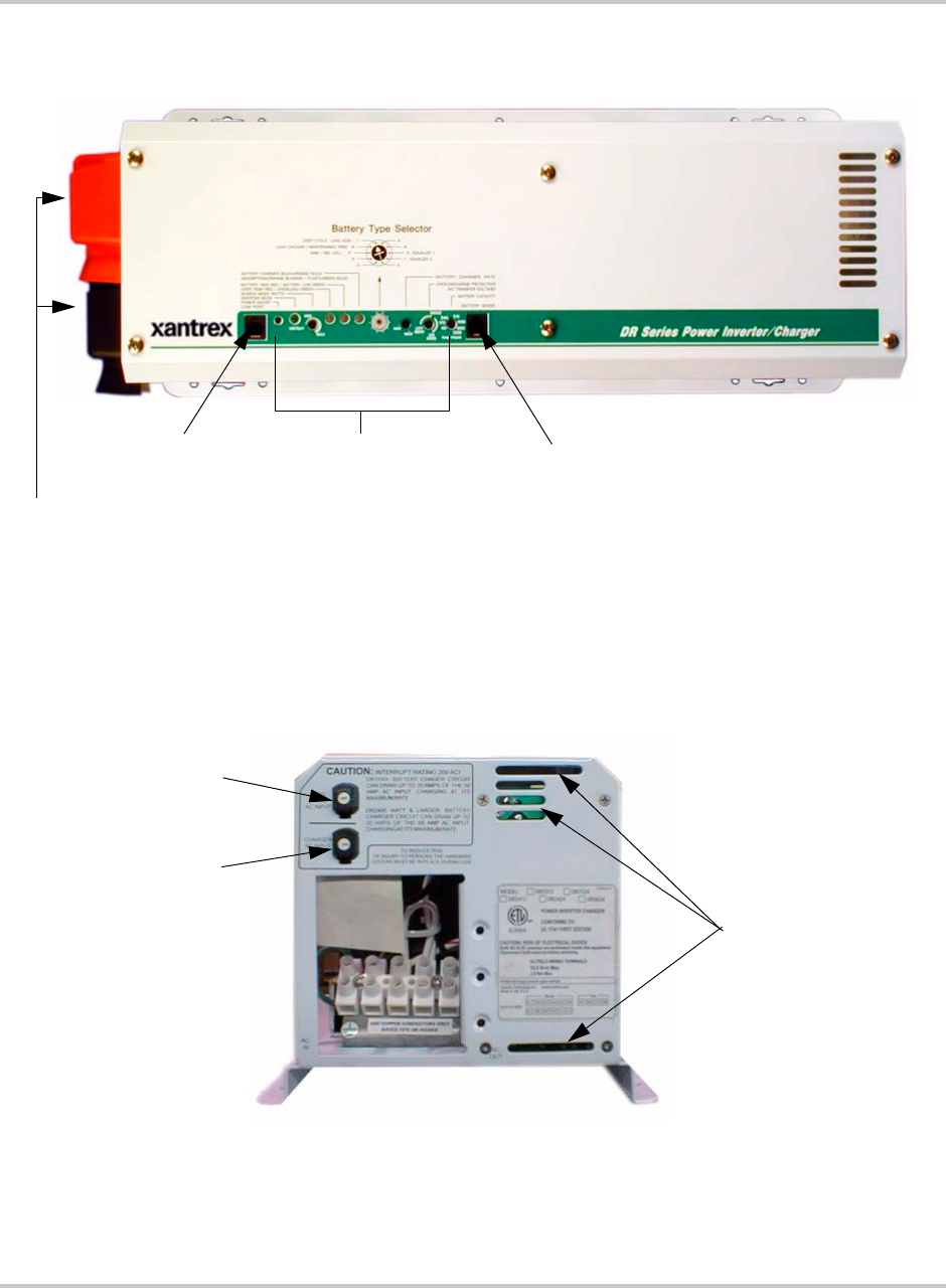
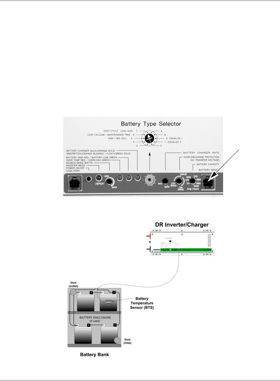
Controls - - - - - - - - - - - - - - - - - - - - - - - - - - - - - - - - - - - - - - - - - - - - - - - - - - - - - - - - - - 3–4
Battery Type Selector - - - - - - - - - - - - - - - - - - - - - - - - - - - - - - - - - - - - - - - - - - - - - - 3–4
SEARCH MODE WATTS Potentiometer - - - - - - - - - - - - - - - - - - - - - - - - - - - - - - - - 3–6
Battery Charger Rate - - - - - - - - - - - - - - - - - - - - - - - - - - - - - - - - - - - - - - - - - - - - - - - - - 3–7
Over Discharge Protection/AC Transfer Voltage - - - - - - - - - - - - - - - - - - - - - - - - - - - 3–8
Over Discharge Protection (ODP) - - - - - - - - - - - - - - - - - - - - - - - - - - - - - - - - - - - - - 3–9
AC Transfer Voltage - - - - - - - - - - - - - - - - - - - - - - - - - - - - - - - - - - - - - - - - - - - - - -3–10
Battery Capacity - - - - - - - - - - - - - - - - - - - - - - - - - - - - - - - - - - - - - - - - - - - - - - - - -3–12
LED Indicators - - - - - - - - - - - - - - - - - - - - - - - - - - - - - - - - - - - - - - - - - - - - - - - - - - - - -3–13
Inverter Mode LED - Green - - - - - - - - - - - - - - - - - - - - - - - - - - - - - - - - - - - - - - - - -3–13
Over Temp / Overload LED - Red / Green (error condition) - - - - - - - - - - - - - - - - - - - -3–13
Battery High/Battery Low LED - Red/Green (error condition) - - - - - - - - - - - - - - - - - -3–13
Charger LED - Orange / Green - - - - - - - - - - - - - - - - - - - - - - - - - - - - - - - - - - - - - - -3–14
Audible Indicator (internal) - - - - - - - - - - - - - - - - - - - - - - - - - - - - - - - - - - - - - - - - - -3–14
Circuit Breakers - - - - - - - - - - - - - - - - - - - - - - - - - - - - - - - - - - - - - - - - - - - - - - - - - - - -3–15

Contents
975-0012-01-02 Rev A xi
Start-up - - - - - - - - - - - - - - - - - - - - - - - - - - - - - - - - - - - - - - - - - - - - - - - - - - - - - - - - - - - - 3–16
Charger Mode - - - - - - - - - - - - - - - - - - - - - - - - - - - - - - - - - - - - - - - - - - - - - - - - - - - - - - - 3–17
3-Stage Charging Process - - - - - - - - - - - - - - - - - - - - - - - - - - - - - - - - - - - - - - - - - - - - - 3–17
Equalize Charging - - - - - - - - - - - - - - - - - - - - - - - - - - - - - - - - - - - - - - - - - - - - - - - - - - 3–18
4
Troubleshooting
Troubleshooting the DR Inverter - - - - - - - - - - - - - - - - - - - - - - - - - - - - - - - - - - - - - - - - - - - - 4–2
Problem Loads - - - - - - - - - - - - - - - - - - - - - - - - - - - - - - - - - - - - - - - - - - - - - - - - - - - - - - - - 4–3
Ceiling Fans - - - - - - - - - - - - - - - - - - - - - - - - - - - - - - - - - - - - - - - - - - - - - - - - - - - - - - - 4–3
Cell Phones - - - - - - - - - - - - - - - - - - - - - - - - - - - - - - - - - - - - - - - - - - - - - - - - - - - - - - - - 4–3
Computers and Sensitive Electronics - - - - - - - - - - - - - - - - - - - - - - - - - - - - - - - - - - - - - - - 4–3
Consumer Electronics - - - - - - - - - - - - - - - - - - - - - - - - - - - - - - - - - - - - - - - - - - - - - - - - - 4–3
Clocks - - - - - - - - - - - - - - - - - - - - - - - - - - - - - - - - - - - - - - - - - - - - - - - - - - - - - - - - - - - 4–4
Decreasing Loads - - - - - - - - - - - - - - - - - - - - - - - - - - - - - - - - - - - - - - - - - - - - - - - - - - - - 4–4
Dimmer Switches - - - - - - - - - - - - - - - - - - - - - - - - - - - - - - - - - - - - - - - - - - - - - - - - - - - - 4–4
Fluorescent Lights - - - - - - - - - - - - - - - - - - - - - - - - - - - - - - - - - - - - - - - - - - - - - - - - - - - 4–4
Heavy Loads - - - - - - - - - - - - - - - - - - - - - - - - - - - - - - - - - - - - - - - - - - - - - - - - - - - - - - - 4–4
Microwave Ovens - - - - - - - - - - - - - - - - - - - - - - - - - - - - - - - - - - - - - - - - - - - - - - - - - - - 4–4
Printers - - - - - - - - - - - - - - - - - - - - - - - - - - - - - - - - - - - - - - - - - - - - - - - - - - - - - - - - - - - 4–5
Rechargeable Devices - - - - - - - - - - - - - - - - - - - - - - - - - - - - - - - - - - - - - - - - - - - - - - - - - 4–5
Undersized Loads - - - - - - - - - - - - - - - - - - - - - - - - - - - - - - - - - - - - - - - - - - - - - - - - - - - - 4–5
A
Specifications
Specifications of the DR Inverter - - - - - - - - - - - - - - - - - - - - - - - - - - - - - - - - - - - - - - - - - - - -A–2
B
Battery Information
Introduction - - - - - - - - - - - - - - - - - - - - - - - - - - - - - - - - - - - - - - - - - - - - - - - - - - - - - - - - - -B–2
Battery Types - - - - - - - - - - - - - - - - - - - - - - - - - - - - - - - - - - - - - - - - - - - - - - - - - - - - - - - - -B–2
Deep-cycle Flooded Lead Acid (FLA) - - - - - - - - - - - - - - - - - - - - - - - - - - - - - - - - - - - - - -B–2
Sealed Batteries (Gel and AGM) - - - - - - - - - - - - - - - - - - - - - - - - - - - - - - - - - - - - - - - - -B–3
NiCad and NiFe Batteries - - - - - - - - - - - - - - - - - - - - - - - - - - - - - - - - - - - - - - - - - - - - - -B–3
Understanding Battery Capacity Ratings - - - - - - - - - - - - - - - - - - - - - - - - - - - - - - - - - - - - - - -B–4
Battery Bank Sizing - - - - - - - - - - - - - - - - - - - - - - - - - - - - - - - - - - - - - - - - - - - - - - - - - - - - -B–4
Understanding Amp-hour Requirements - - - - - - - - - - - - - - - - - - - - - - - - - - - - - - - - - - - -B–5
Calculating Amp Hours - - - - - - - - - - - - - - - - - - - - - - - - - - - - - - - - - - - - - - - - - - - - - - - -B–5
Amp Hour Example Worksheet - - - - - - - - - - - - - - - - - - - - - - - - - - - - - - - - - - - - - - -B–6
Battery bank size worksheet - - - - - - - - - - - - - - - - - - - - - - - - - - - - - - - - - - - - - - - - - -B–7
Battery Configurations - - - - - - - - - - - - - - - - - - - - - - - - - - - - - - - - - - - - - - - - - - - - - - - - - - -B–8
Wiring Batteries in Series - - - - - - - - - - - - - - - - - - - - - - - - - - - - - - - - - - - - - - - - - - - - - -B–8
Wiring Batteries in Parallel - - - - - - - - - - - - - - - - - - - - - - - - - - - - - - - - - - - - - - - - - - - - -B–9
Wiring Batteries in Series-Parallel - - - - - - - - - - - - - - - - - - - - - - - - - - - - - - - - - - - - - - - B–10
Battery Connections for Stacked Inverters - - - - - - - - - - - - - - - - - - - - - - - - - - - - - - - - - - B–12

Contents
xii 975-0012-01-02 Rev A
Battery Maintenance - - - - - - - - - - - - - - - - - - - - - - - - - - - - - - - - - - - - - - - - - - - - - - - - - - - B–13
Battery Charging - - - - - - - - - - - - - - - - - - - - - - - - - - - - - - - - - - - - - - - - - - - - - - - - - - - B–13
Equalization Charging - - - - - - - - - - - - - - - - - - - - - - - - - - - - - - - - - - - - - - - - - - - - - - - B–15
General Maintenance - - - - - - - - - - - - - - - - - - - - - - - - - - - - - - - - - - - - - - - - - - - - - - - - B–16
C
Multi-wire Branch Circuit Wiring
Multi-wire Branch Circuits - - - - - - - - - - - - - - - - - - - - - - - - - - - - - - - - - - - - - - - - - - - - - - - C–2
Identifying Multi-wire Branch Circuits - - - - - - - - - - - - - - - - - - - - - - - - - - - - - - - - - - - - - - - C–4
Correcting Multi-wire Branch Circuit Wiring - - - - - - - - - - - - - - - - - - - - - - - - - - - - - - - - - - - C–5
Warranty and Return Information
- - - - - - - - - - - - - - - - - - - - - - - - - - - - - - - - - - - WA–1
Index
- - - - - - - - - - - - - - - - - - - - - - - - - - - - - - - - - - - - - - - - - - - - - - - - - - - - - - - - - - - - - - - IX–1

975-0012-01-02 Rev A xiii
Figure 1-1 Front Panel Features - - - - - - - - - - - - - - - - - - - - - - - - - - - - - - - - - - - - - - - - - - - - - - 1–3
Figure 1-2 AC Side of the DR Inverter- - - - - - - - - - - - - - - - - - - - - - - - - - - - - - - - - - - - - - - - - - 1–3
Figure 1-3 DC Side of the DR Inverter- - - - - - - - - - - - - - - - - - - - - - - - - - - - - - - - - - - - - - - - - - 1–4
Figure 1-4 Product Identification - - - - - - - - - - - - - - - - - - - - - - - - - - - - - - - - - - - - - - - - - - - - - 1–5
Figure 1-5 Model/Serial Number Sticker - - - - - - - - - - - - - - - - - - - - - - - - - - - - - - - - - - - - - - - - 1–6
Figure 2-1 On-Grid Basic Configuration (Utility Backup)- - - - - - - - - - - - - - - - - - - - - - - - - - - - - 2–7
Figure 2-2 Off-Grid Configuration (Generator only) - - - - - - - - - - - - - - - - - - - - - - - - - - - - - - - - 2–7
Figure 2-3 On-Grid Configuration - with Renewable Energy Sources - - - - - - - - - - - - - - - - - - - - - 2–8
Figure 2-4 Off-Grid Configuration - with Renewable Energy Sources- - - - - - - - - - - - - - - - - - - - - 2–9
Figure 2-5 Charge Rate versus Peak AC Voltage- - - - - - - - - - - - - - - - - - - - - - - - - - - - - - - - - - 2–10
Figure 2-6 Dimensions (not to scale) - - - - - - - - - - - - - - - - - - - - - - - - - - - - - - - - - - - - - - - - - - 2–11
Figure 2-7 Suggested Mounting Method - - - - - - - - - - - - - - - - - - - - - - - - - - - - - - - - - - - - - - - 2–12
Figure 2-8 Mounting on Plywood - - - - - - - - - - - - - - - - - - - - - - - - - - - - - - - - - - - - - - - - - - - - 2–12
Figure 2-9 DC Grounding - - - - - - - - - - - - - - - - - - - - - - - - - - - - - - - - - - - - - - - - - - - - - - - - - 2–14
Figure 2-10 Battery Cable Connections - - - - - - - - - - - - - - - - - - - - - - - - - - - - - - - - - - - - - - - - - 2–18
Figure 2-11 DC Terminals on the DR Inverter - - - - - - - - - - - - - - - - - - - - - - - - - - - - - - - - - - - - 2–19
Figure 2-12 Connecting the Battery Bank to the DR Inverter/Charger- - - - - - - - - - - - - - - - - - - - - 2–20
Figure 2-13 Battery Temperature Sensor (BTS) RJ11 Jack Location - - - - - - - - - - - - - - - - - - - - - 2–21
Figure 2-14 Connecting the BTS to the DR Inverter - - - - - - - - - - - - - - - - - - - - - - - - - - - - - - - - 2–21
Figure 2-15 AC Side Cover Panels - - - - - - - - - - - - - - - - - - - - - - - - - - - - - - - - - - - - - - - - - - - - 2–23
Figure 2-16 AC Terminals for AC Input to the Inverter - - - - - - - - - - - - - - - - - - - - - - - - - - - - - - 2–24
Figure 2-17 AC Terminals for AC output to the Sub-panel - - - - - - - - - - - - - - - - - - - - - - - - - - - - 2–25
Figure 2-18 AC Wiring- On-Grid Application - - - - - - - - - - - - - - - - - - - - - - - - - - - - - - - - - - - - 2–26
Figure 2-19 AC Wiring using a Generator - On-Grid Application - - - - - - - - - - - - - - - - - - - - - - - 2–27
Figure 2-20 AC Wiring using a 120 Vac Generator - Off-Grid Application - - - - - - - - - - - - - - - - - 2–28
Figure 2-21 AC Wiring using a 240 Vac Generator with 120 Vac Loads only- Off-Grid Application 2–29
Figure 2-22 AC Wiring for dual-inverters - On-Grid Application (120 Vac models only) - - - - - - - 2–31
Figure 2-23 Wiring for dual-inverters - On-Grid Application (120 Vac models only) - - - - - - - - - - 2–32
Figure 3-1 Front Panel Controls and Indicators - - - - - - - - - - - - - - - - - - - - - - - - - - - - - - - - - - - - 3–2
Figure 3-2 Battery Type Selector Adjustment - - - - - - - - - - - - - - - - - - - - - - - - - - - - - - - - - - - - - 3–4
Figure 3-3 Battery Type Selector Adjustment - - - - - - - - - - - - - - - - - - - - - - - - - - - - - - - - - - - - - 3–7
Figure 3-4 Battery Charger Rate Potentiometer (DR1512 values used) - - - - - - - - - - - - - - - - - - - - 3–8
Figure 3-5 ODP Enabled/Disabled Positions- - - - - - - - - - - - - - - - - - - - - - - - - - - - - - - - - - - - - - 3–9
Figure 3-6 Automatically Calculated Discharge Cutoff Voltage per Cell - - - - - - - - - - - - - - - - - - - 3–9
Figure 3-7 ODP Enabled/Disabled Positions- - - - - - - - - - - - - - - - - - - - - - - - - - - - - - - - - - - - - 3–11
Figure 3-8 Typical Setting for Most Utility Application - - - - - - - - - - - - - - - - - - - - - - - - - - - - - 3–11
Figures

Figures
xiv 975-0012-01-02 Rev A
Figure 3-9 Battery Capacity Potentiometer (new) - - - - - - - - - - - - - - - - - - - - - - - - - - - - - - - - - -3–12
Figure 3-10 Battery Capacity Potentiometer (old)- - - - - - - - - - - - - - - - - - - - - - - - - - - - - - - - - - -3–12
Figure 3-11 LED Indicators - - - - - - - - - - - - - - - - - - - - - - - - - - - - - - - - - - - - - - - - - - - - - - - - -3–13
Figure 3-12 AC Pass-through and Charger AC Input Circuit Breakers - - - - - - - - - - - - - - - - - - - - -3–15
Figure 3-13 Startup Items - - - - - - - - - - - - - - - - - - - - - - - - - - - - - - - - - - - - - - - - - - - - - - - - - - -3–16
Figure 3-14 Charger Controls and Indicators - - - - - - - - - - - - - - - - - - - - - - - - - - - - - - - - - - - - - -3–18
Figure 3-15 Equalize Positions on Battery Type Selector Switch - - - - - - - - - - - - - - - - - - - - - - - -3–19
Figure 3-16 Equalize 1 Battery Charger Rate Potentiometer (Position “1”)- - - - - - - - - - - - - - - - - -3–20
Figure 3-17 Equalize 2 Battery Capacity Rate Potentiometer (Position “0”) - - - - - - - - - - - - - - - - -3–20
Figure B-1 6-volt Battery Wiring - “Series” Configuration - - - - - - - - - - - - - - - - - - - - - - - - - - - - B–8
Figure B-2 12-volt Battery Wiring - “Series” Configuration - - - - - - - - - - - - - - - - - - - - - - - - - - - B–9
Figure B-3 Battery Wiring in Parallel - - - - - - - - - - - - - - - - - - - - - - - - - - - - - - - - - - - - - - - - - - B–9
Figure B-4 Battery Wiring 24-volt - Parallel Configuration - Step 1 - - - - - - - - - - - - - - - - - - - - - B–10
Figure B-5 Battery Wiring 24-volt - Parallel Configuration - Step 2 - - - - - - - - - - - - - - - - - - - - - B–10
Figure B-6 Battery Wiring 24-volt - Parallel Configuration - Step 3 - - - - - - - - - - - - - - - - - - - - - B–11
Figure B-7 Example of Battery Connections for Stacked Inverters (24 Vdc shown) - - - - - - - - - - B–12
Figure C-1 Conventional Home-type Wiring - - - - - - - - - - - - - - - - - - - - - - - - - - - - - - - - - - - - - C–2
Figure C-2 Multi-wire Branch Circuit Wiring and Current Flow - - - - - - - - - - - - - - - - - - - - - - - - C–3
Figure C-3 120 Vac Inverter Incorrectly Wired in a Multi-wire Branch Circuit - - - - - - - - - - - - - - C–3
Figure C-4 Multi-wire Branch Circuit Wiring- - - - - - - - - - - - - - - - - - - - - - - - - - - - - - - - - - - - - C–4
Figure C-5 Using a Step-down Autotransformer in Multi-wire Branch Circuit Wiring - - - - - - - - C–6S

975-0012-01-02 Rev A xv
Table 1-1 Model Identification and Numbering Conventions - - - - - - - - - - - - - - - - - - - - - - - - - - 1–5
Table 1-2 Letter Suffix Code Definitions - - - - - - - - - - - - - - - - - - - - - - - - - - - - - - - - - - - - - - - 1–6
Table 2-1 Peak Input Filtrate versus Charging Current - - - - - - - - - - - - - - - - - - - - - - - - - - - - - 2–10
Table 2-2 Safety Ground Conductor Size - - - - - - - - - - - - - - - - - - - - - - - - - - - - - - - - - - - - - - 2–13
Table 2-3 Minimum Recommended Battery Cable Size versus Length - - - - - - - - - - - - - - - - - - 2–16
Table 2-4 Battery Cable to Maximum Breaker/Fuse Size- - - - - - - - - - - - - - - - - - - - - - - - - - - - 2–17
Table 2-5 Minimum Recommended Wire Size, Torque Values (Input and Output),
and Maximum Output Breaker Size - - - - - - - - - - - - - - - - - - - - - - - - - - - - - - - - - - - 2–23
Table 3-1 Battery Type Selector Switch Settings - - - - - - - - - - - - - - - - - - - - - - - - - - - - - - - - - - 3–5
Table 3-2 Approximate Charge rate Setting/Amperage - - - - - - - - - - - - - - - - - - - - - - - - - - - - - - 3–8
Table 3-3 ODP/AC Transfer Voltage - - - - - - - - - - - - - - - - - - - - - - - - - - - - - - - - - - - - - - - - - 3–10
Table 3-4 AC Pass-through Circuit Breakers - - - - - - - - - - - - - - - - - - - - - - - - - - - - - - - - - - - - 3–15
Table 3-5 Battery Charger Circuit Breakers - - - - - - - - - - - - - - - - - - - - - - - - - - - - - - - - - - - - - 3–15
Table 4-1 Troubleshooting the DR Inverter - - - - - - - - - - - - - - - - - - - - - - - - - - - - - - - - - - - - - - 4–2
Table A-1 Electrical Specifications for the DR Inverter/Charger - 120 Vac/60 Hz Models - - - - - - -A–2
Table A-2 Electrical Specifications for the DR Inverter/Chargers - 220 Vac/60 Hz Models - - - - - -A–4
Table A-3 Electrical Specifications for the DR Inverter/Charger - 230 Vac/50 Hz Models - - - - - - -A–5
Table A-4 Environmental Specifications for the DR Inverter/Charger - - - - - - - - - - - - - - - - - - - -A–7
Table B-1 Determining Average Daily Load in Amp-hours (Example - - - - - - - - - - - - - - - - - - - -B–6
Table B-2 Determining Battery Bank Size - - - - - - - - - - - - - - - - - - - - - - - - - - - - - - - - - - - - - - -B–7
Table B-3 Typical Appliance Wattage- - - - - - - - - - - - - - - - - - - - - - - - - - - - - - - - - - - - - - - - - -B–7
Table B-4 Variances in Charging Voltage based on Battery Temperature - - - - - - - - - - - - - - - - - B–14
Table B-5 Temperature Compensation Calculation - - - - - - - - - - - - - - - - - - - - - - - - - - - - - - - - B–14
Table B-6 Battery State-of-Charge - - - - - - - - - - - - - - - - - - - - - - - - - - - - - - - - - - - - - - - - - - - B–17
Tables
xvi
1Introduction
Chapter 1, “Introduction” contains information about the features and
functions of the DR Inverter/Charger.

Introduction
1–2 975-0012-01-02 Rev A
Introduction
Thank you for purchasing the DR Inverter/Charger from Xantrex Technology Inc.
The DR Inverter is one of the finest inverter/chargers on the market today,
incorporating state-of-the-art technology and high reliability.
The inverter features an AC pass-through circuit, powering your home appliances
from utility or generator power while charging the batteries. When utility power
fails, the battery backup system keeps your appliances powered until utility power
is restored. Internal protection circuits prevent over-discharge of the batteries by
shutting down the inverter when a low battery condition occurs. When utility or
generator power is restored, the inverter transfers to the AC source and recharges
the batteries.
The front panel features LEDs for reading system status, and controls to
customize the inverter settings for your battery bank.
The DR Inverter is an economical product designed to provide a reliable supply of
electricity to all the essential circuits in the home or business during a power
outage. The critical loads can be powered for hours or days, depending on the size
of the system battery bank. When utility grid power returns, the batteries are
quickly recharged to ensure they will be ready to supply backup power during the
next outage.
Accessories allow the DR Series to also serve as a central hub of a renewable
energy system.
Modified Sine
Wave Power
The DR Inverter provide a modified sine wave output which operates most AC
appliances and equipment.
Battery Charger/AC
Transfer Relay
The inverter/charger includes a 3-stage battery charger designed to recharge any
type of battery in the shortest possible time. The built-in, fully automatic AC
transfer relay automatically transfers power from the utility to the inverter and
handles a full 60 amps of current at 120 Vac (30 amps for pass-through plus
20 to 30 amps for charging - depending on the model).
Simplicity The DR Inverter is simple to operate. All inverter and battery charger controls are
located on the front panel.
High Efficiency The inverter/charger operates at over 90% efficiency through most of its power
range in Invert-mode.
Low Power
Consumption
DR Inverter use extremely low current while in the search mode, consuming less
than 1 watt of power. In the ON mode, the inverter/charger uses less than 12 watts
of power.
Features
The following sections illustrate the features of the DR Inverter. Figure 1-1 shows
the features of the front side of the DR Inverter and identifies the AC side from the
DC side.
Features
975-0012-01-02 Rev A 1–3
AC Side
The AC side of the DR Inverter has one 30-amp breaker for pass-thru AC Input,
and one 30-amp (20 amp in certain models) breaker for charger AC input.
Figure 1-1
Front Panel Features
DC End
Front Panel Controls
and Indicators
Battery Caps
AC End
Battery Sense Port
COM Port
Figure 1-2
AC Side of the DR Inverter
30 Amp Breaker for
Pass-thru AC Input
20 or 30 Amp Breaker
for Charger AC Input
Cover plate is not shown
in this photo.
Ventilation Holes
Introduction
1–4 975-0012-01-02 Rev A
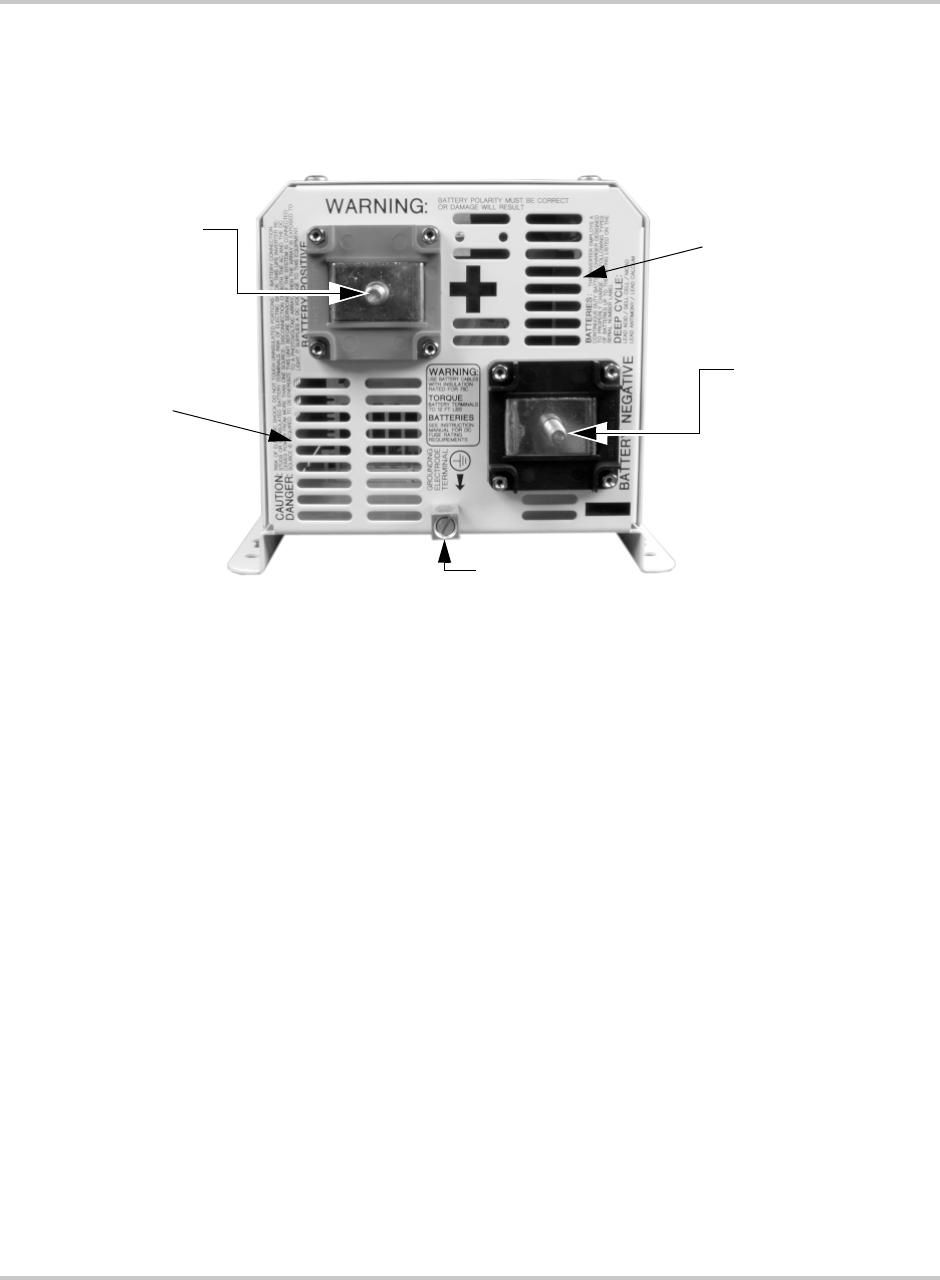
DC Side
The DC side of the DR Inverter has the equipment ground lug, the positive (+)
battery terminal, and the negative (–) battery terminal.
Optional Equipment
The following options are available for the DR Inverter/Chargers.
Remote Control (RC8)
The RC8 allows the inverter to be switched ON or OFF remotely and includes an
LED status indicator. This unit is also compatible with the RC4 (the predecessor
to the RC8); although the RC4 is no longer available for purchase from Xantrex.
Stacking Interface (DRI)
The DRI stacking interface provides 3-wire 120/240 Vac at twice the power using
dual DR Inverters (120 Vac/60 Hz units only).
Conduit Box (DRCB)
The DRCB conduit box connects to the DC side of the inverter and accepts a DC
conduit run.
Unpacking and Inspection
Carefully unpack the inverter/charger from its shipping carton.
Figure 1-3
DC Side of the DR Inverter
Ventilation Holes
Battery Positive
(+) Terminal
Ventilation Holes
Ground Lug
Battery Negative
(–) Terminal

Features
975-0012-01-02 Rev A 1–5
❐Verify all of the items listed on the packing material sheet are present. Please
call Xantrex Customer Service at (800) 670-0707 if any items are missing.
❐Save your proof-of-purchase. This is required if the unit should require
warranty service.
❐Save the original shipping carton and packing materials! If the inverter ever
needs to be returned for service, it should be shipped in the original carton.
This is also a good way to protect the inverter if it ever needs to be moved.
❐Record the unit’s model, serial number and date of purchase in the appropriate
fields in section “Information About Your System” on page WA–4.
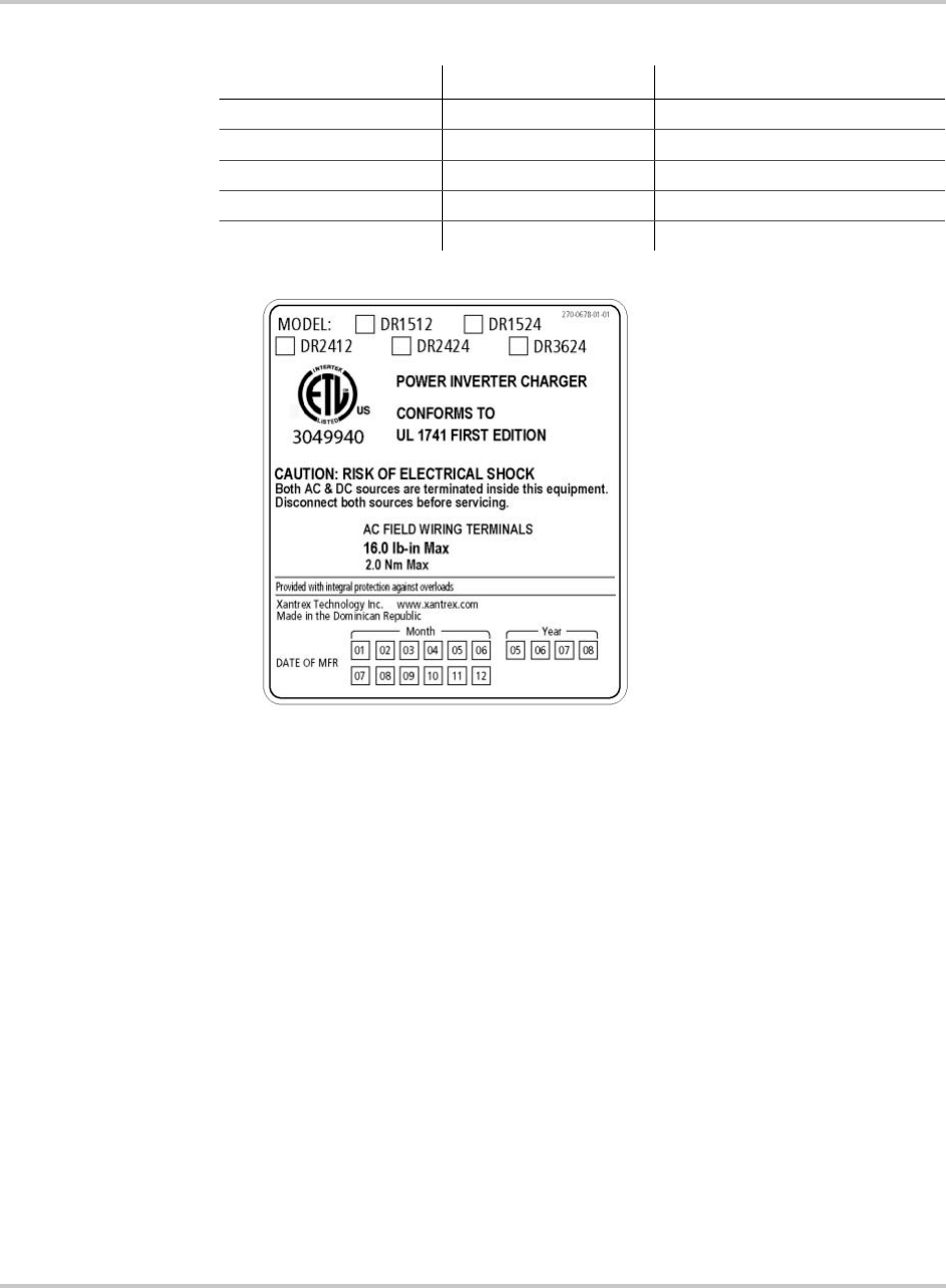
Model Identification and Numbering Conventions
The DR Inverter is identified by the model/serial number labels. The Serial
Number can be located on the mounting rail or inside the top cover. Model
Number labels may be located on the bottom side of the front cover or possibly
inside the front cover. All the necessary information is provided on the label such
as AC output voltage, power and frequency (punch holes).
The inverter also has a letter designator followed by 4 or 5 digits (depending on
revision). The model number describes the type of inverter, the output
specifications, the required battery voltage and the output voltage and frequency
Important:
The unit weighs 35–45 lb/15.9–20.4 kg (depending on model). Have
additional help available if necessary, to assist in lifting the unit during installation.
Important:
Due to continual improvement through product updates, photographs and/
or illustrations used in this manual may not exactly match your unit. Xantrex Technology
Inc. reserves the right to update this product without notice or releasing an updated
manual when fit, form or function are not affected.
Table 1-1
Model Identification and Numbering Conventions
DR indicates the type of inverter/charger - DR Series.
15
the first two digits of the numerical designator indicate the inverter’s output
power - 1500 Watts.
12
the second two digits indicate the required nominal battery bank voltage -
12 Vdc.
E
the letter suffix code indicates the output voltage and frequency of the inverter -
230 Vac/50 Hz.
Figure 1-4
Product Identification
Product Family
Output Power
Example: DR 1512 E
Country Code
(Letter Suffix)
Battery Voltage
Introduction
1–6 975-0012-01-02 Rev A
Regulatory
The 120 Vac/60 Hz models of the DR Series inverter/charger (models DR1512,
DR1524, DR2412, DR2424, and DR3624) are ETL Listed to UL Standard 1741,
(First Edition) Power Conditioning Units for use in Residential and Commercial
Photovoltaic Power Systems.
These standards guarantee that the DR Inverter/Charger has been tested to
nationally recognized safety standards (UL for the US) and have been found to be
free from reasonably foreseeable risk of fire, electric shock and related hazards.
The DR Inverter/Charger is intended to be used for residential or commercial
applications. Do NOT use this unit for applications for which it is not listed
(i.e., land vehicles or marine craft). It may not comply with the safety code
requirements or could possibly present other operational or safety hazards.
Table 1-2
Letter Suffix Code Definitions
Letter Suffix Output Voltage Output frequency
(no letter) 120 Vac 60 Hz
E 230 Vac 50 Hz
J 105 Vac 50 Hz
K 105 Vac 60 Hz
W 220 Vac 60 Hz
Figure 1-5
Model Number Sticker
2Installation
Chapter 2, “Installation” contains information about how to plan for
and install the DR Inverter/Charger.
Installation
2–2 975-0012-01-02 Rev A
Pre-installation Planning
Take some time prior to installing the equipment to pre-plan the installation.
Location, mounting, and ventilation should be taking into consideration before
any cabling can be done.
Location
Inverters contain sophisticated electronic components and should be located in a
well protected, dry environment away from sources of fluctuating or extreme
temperatures and moisture. Exposure to saltwater is particularly destructive and
potentially hazardous.
Locate the inverter as close to the batteries as possible in order to keep the battery
cable length short. However, do not locate the inverter above the batteries or in the
same compartment as vented batteries. Batteries generate hydrogen sulfide gas
which is corrosive to electronic equipment. They also generate hydrogen and
oxygen. If accumulated, an arc caused by connecting the battery cables or
switching a relay could ignite this mixture. Mounting the inverter in a ventilated
enclosure with sealed batteries is acceptable.
Important:
Before installing and using the DR Inverter/Charger, read all instructions
and cautionary markings on the DR Inverter/Charger and all appropriate sections of this
guide. Be sure to read all instructions and cautionary markings for any equipment attached
to this unit.
CAUTION: Personal Injury
The inverter/charger can weigh up to 45 lbs (20.4 kg) depending upon configuration.
Always use proper lifting techniques during installation to prevent personal injury.
CAUTION: Corrosion Damage
If the inverter is installed in a location where it is exposed to a corrosive or condensing
environment and fails due to corrosion, it will not be covered under warranty.
Important:
Inverters can generate RFI (Radio Frequency Interference). Locate any
sensitive electronic equipment susceptible to RFI as far away from the inverter as
possible. This includes radios and TVs.

Pre-installation Planning
975-0012-01-02 Rev A 2–3
Mounting
The National Building Code requires the inverter be mounted on a vertical surface
(or wall). The keyhole slots must not be used as the only method of mounting. The
purpose of the wall mounting requirement is to orient the inverter so that its
bottom cover, which has no holes, will not allow burning material to be ejected in
the event of an internal fire. Use 0.25-inch diameter bolts for mounting. The
mounting surface must be capable of supporting twice the weight of the inverter to
comply with UL 1741.
Ventilation
Install the inverter in a well ventilated area/enclosure for proper operation. The
inverter’s thermal shutdown point will be reached sooner than normal in a poorly
ventilated environment, resulting in reduced peak power output and surge
capability, as well as shorter inverter life.
The inverter contains an internal fan. Ensure the air vents and intakes are not
obstructed in any way. Provide a minimum clearance of 6 inches around the top
and sides of the inverter for ventilation.
Tools Required
The following tools may be required to complete this installation.
❐#2 Phillips screw driver
❐Slotted screw driver
❐Assorted open-end wrenches
❐Socket wrench and fittings
❐Multimeter (True rms)
❐Hole saw
❐Level
❐Wire strippers
❐Torque wrench
❐Electrical tape
❐Pencil
❐Utility knife

Installation
2–4 975-0012-01-02 Rev A
Hardware / Materials Required
The following hardware or materials may be required to complete this installation.
❐4 ft. x 4 ft. sheet of 3/4" plywood or 2 x 4’s studding material
❐#12 wood screws (or 1/2" x 1-1/4" lag bolts)
❐Conduit and appropriate fittings
❐Wire nuts
Wiring Considerations
All wiring and installation methods should conform to applicable electrical and
building codes.
Pre-plan the wire and conduit runs.
• The AC terminals accept cable sizes up to #6 AWG.
• The DC terminals accept cable sizes up to #4/0 AWG that use ring terminals
with 5/16" holes.
For maximum safety, run both AC and DC cables in conduit.
DC Terminal Connections
Battery-to-inverter cabling should be only as long as required.
For Example: If #4/0 AWG cables are used, do not exceed 5 feet (one way) in
12 Vdc systems; do not exceed 10 feet (one way) in 24 Vdc systems.
For optimum performance, use pre-assembled battery cables designed specifically
for this application (available from Xantrex).
Grounding Considerations
AC Grounding
The inverter/charger should be connected to a grounded, permanent wiring
system. Neutral and ground conductors should only be bonded at the main
electrical service panel.
DC Grounding
The negative battery conductor should be bonded to the grounding system at only
one point in the system. The size for the conductor is usually based on the size of
the largest conductor in the DC system.

Pre-installation Planning
975-0012-01-02 Rev A 2–5
Wire Routing
Determine all wire routes both to and from the inverter and which knockouts are
best suited for connecting the AC conduits. Possible routing scenarios include:
• AC input wiring from the main electrical service panel to the inverter/charger
(if used)
• AC input wiring from the generator to the inverter/charger (if used)
• DC input wiring from the RE to the inverter/charger (if used)
• DC input wiring from the batteries to the inverter/charger
• AC output wiring from the inverter/charger to the sub-panel
• Battery Temperature Sensor cable from the batteries to the inverter/charger (if
used)
• Remote control cable to the inverter/charger (if used)
• DC ground from the batteries to an external ground rod
• Load circuit wiring rerouted from the main service panel to the sub-panel
Check for existing electrical or plumbing prior to making cuts in the walls. Cut
holes in the walls at appropriate locations for routing wiring/cables.
Electrical Panels and Circuit Breaker Requirements
The following electrical panels and circuit breakers may be required for this
installation.
AC Distribution Panel (Sub-Panel)
Loads backed up by the inverter will need to be rerouted from the main electrical
panel to a sub-panel. This can be done several different ways, depending upon the
installation. Always refer to electrical codes for safe wiring practices.
DC Disconnect
Install a DC disconnect breaker or fuse in the positive battery line. This breaker
protects the DC wiring in the event of an accidental short. Size the breaker in
accordance with the battery cables. Switch this breaker OFF whenever servicing
the batteries.
Battery Considerations
The DR Inverter can support either 12-volt battery banks or 24-volt battery banks.
The battery voltage MUST match the voltage requirements of the inverter. To
determine the correct voltage for the system, check the last two digits on the
inverter’s model number. For example, the DR1512 is a 12-volt inverter and
requires a 12 Vdc battery system. The DR2424 is a 24-volt inverter and requires a
24 Vdc battery system.

Installation
2–6 975-0012-01-02 Rev A
Battery Location
Locate the batteries in an accessible location. Two feet clearance above the
batteries is recommended for access to the battery caps. They should be located as
close to the inverter as possible without limiting access to the inverter’s
disconnects. Install the batteries to the left of a wall mounted inverter for easy
access to the DC side of the inverter and shorter cable runs.
For safety and to limit access to the batteries, a lockable, ventilated, battery
enclosure or dedicated room should be used. If an enclosure is used, it should be
vented to the outside via a one inch vent pipe located at the top of the enclosure.
Install an intake vent at the bottom of the enclosure to promote air circulation.
These vents exhaust explosive hydrogen gases and must not be overlooked when
designing an enclosure.
The enclosure should be made of an acid resistant material or have a finish that
resists acid to prevent corrosion. It should be capable of holding the electrolyte
from at least one battery should a leak occur.
Place a layer of baking soda on the shelves to neutralize any acid that may be
spilled in the future (lead-acid batteries only).
Enclosures located outside must be rainproof and screened to prevent access by
rodents or insects.
Battery Temperature
The battery enclosure should provide a fairly stable temperature for the batteries.
If it is installed in a cold environment, insulation should be used to protect the
batteries from the cold. The insulation also provides a more consistent
temperature and better system performance.
The battery enclosure should not be installed in direct sunlight where the summer
sun can overheat the batteries. Locate the enclosure where it will be protected
from the afternoon sun and provide vents in the top and bottom of the enclosure to
provide air flow. High battery temperatures greatly shortens the life of the
batteries.
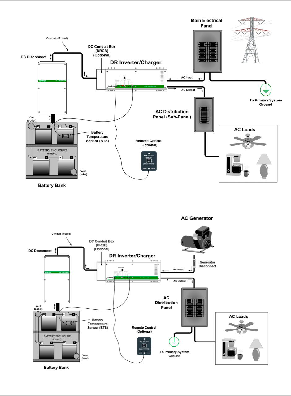
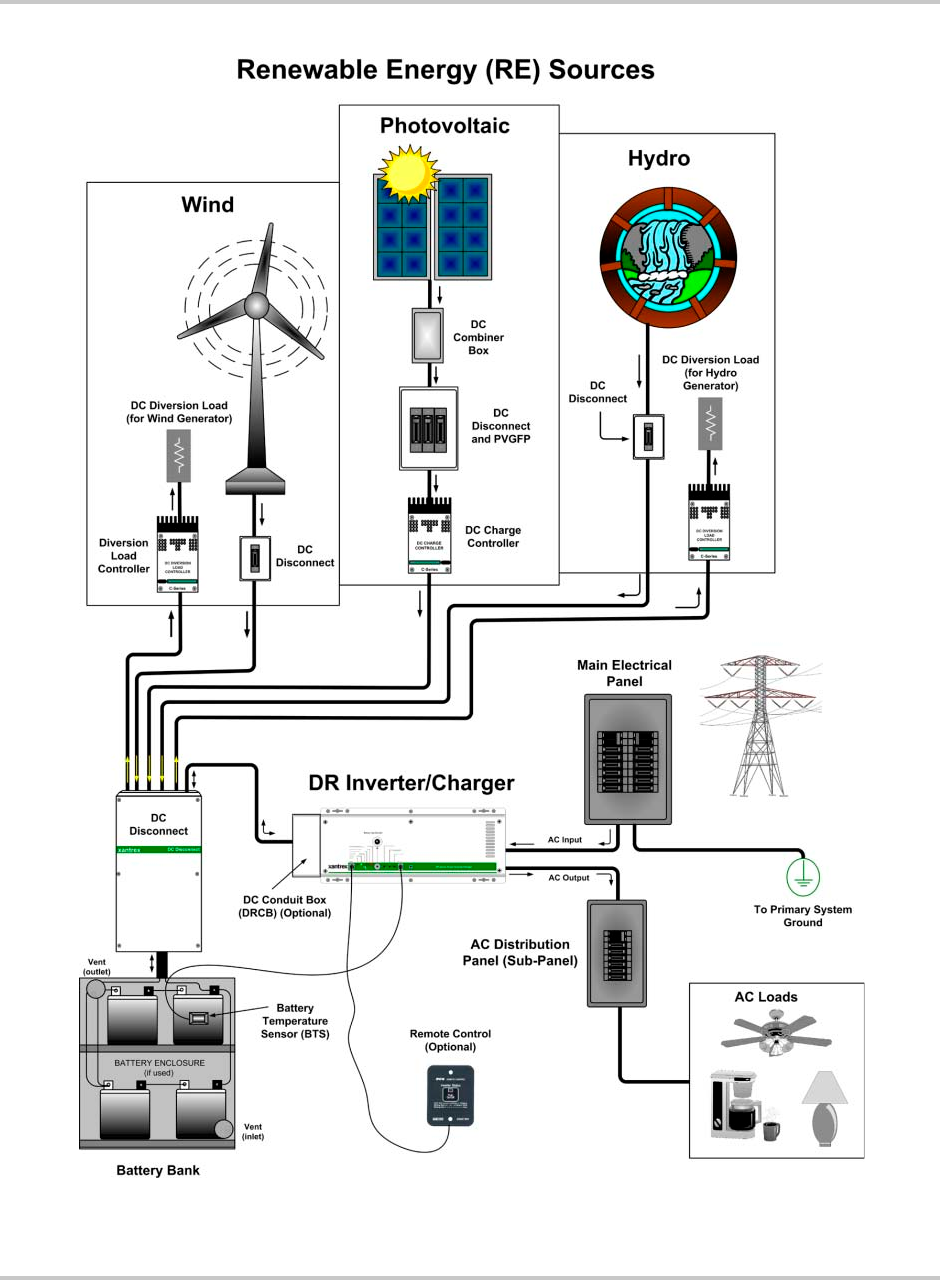
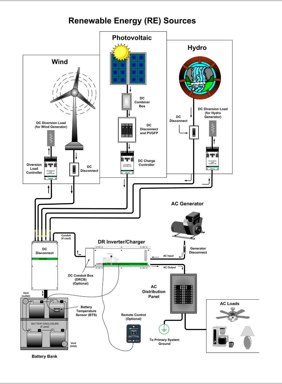
Basic Configurations
The following illustrations show basic applications for the DR Inverter/Charger.
They include the following configurations.
• On-Grid Configuration - Utility Backup
• Off-Grid Configuration - Generator only
• On-Grid Configuration with Renewable Energy Sources
• Off-Grid Configuration with Renewable Energy Sources and a Generator
Consult with your system design for other possible configurations depending on
site and code requirements.
Pre-installation Planning
975-0012-01-02 Rev A 2–7
Figure 2-1
On-Grid Basic Configuration (Utility Backup)
Figure 2-2
Off-Grid Configuration (Generator only)
Installation
2–8 975-0012-01-02 Rev A
Figure 2-3
On-Grid Configuration - with Renewable Energy Sources
Pre-installation Planning
975-0012-01-02 Rev A 2–9
Figure 2-4
Off-Grid Configuration - with Renewable Energy Sources
Installation
2–10 975-0012-01-02 Rev A
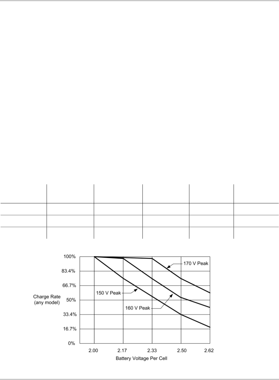
Generators
An AC generator can be used as an input source instead of the utility power, or
can be connected (using additional hardware) to power the loads when utility is
not present (utility outage), and to charge the batteries. The generator must be of
the permanently installed type and not a portable type unit used for emergency
power. Small emergency type (lower power) generators may not have a stable
enough voltage for the inverter to synchronize to or provide enough current to
fully charge the batteries.
The maximum charge rate the battery charger can deliver is dependant upon the
peak AC voltage available. Since the battery charger uses only the top portion of
the input sine wave, small variations in peak voltage result in large variations in
the amount of energy to the charger. The charger’s rated output is based on a
utility voltage of 120 Vac RMS (the usual measured value). This should have a
peak voltage of 169 Vacpp (230 Vac has a peak voltage of 325 Vac). For every 10
volts of peak lost, the charge rate is reduced by approximately half.
Size the generator appropriately for the system, including battery charge and load
current (typically twice the wattage output of the inverter).
Table 2-1 and Figure 2-5 demonstrates how the peak voltage available affects the
charging current.
Table 2-1
Peak Input Filtrate versus Charging Current
Peak Voltage
Available DR1512 DR2412 DR1524 DR242 DR3624
170 Vacp70 amps 120 amps 35 amps 70 amps 70 amps
160 Vacp35 amps 60 amps 17.5 amps 35 amps 35 amps
145 Vacp15 amps 25 amps 7 amps 15 amps 15 amps
Figure 2-5
Charge Rate versus Peak AC Voltage
Pre-installation Planning
975-0012-01-02 Rev A 2–11
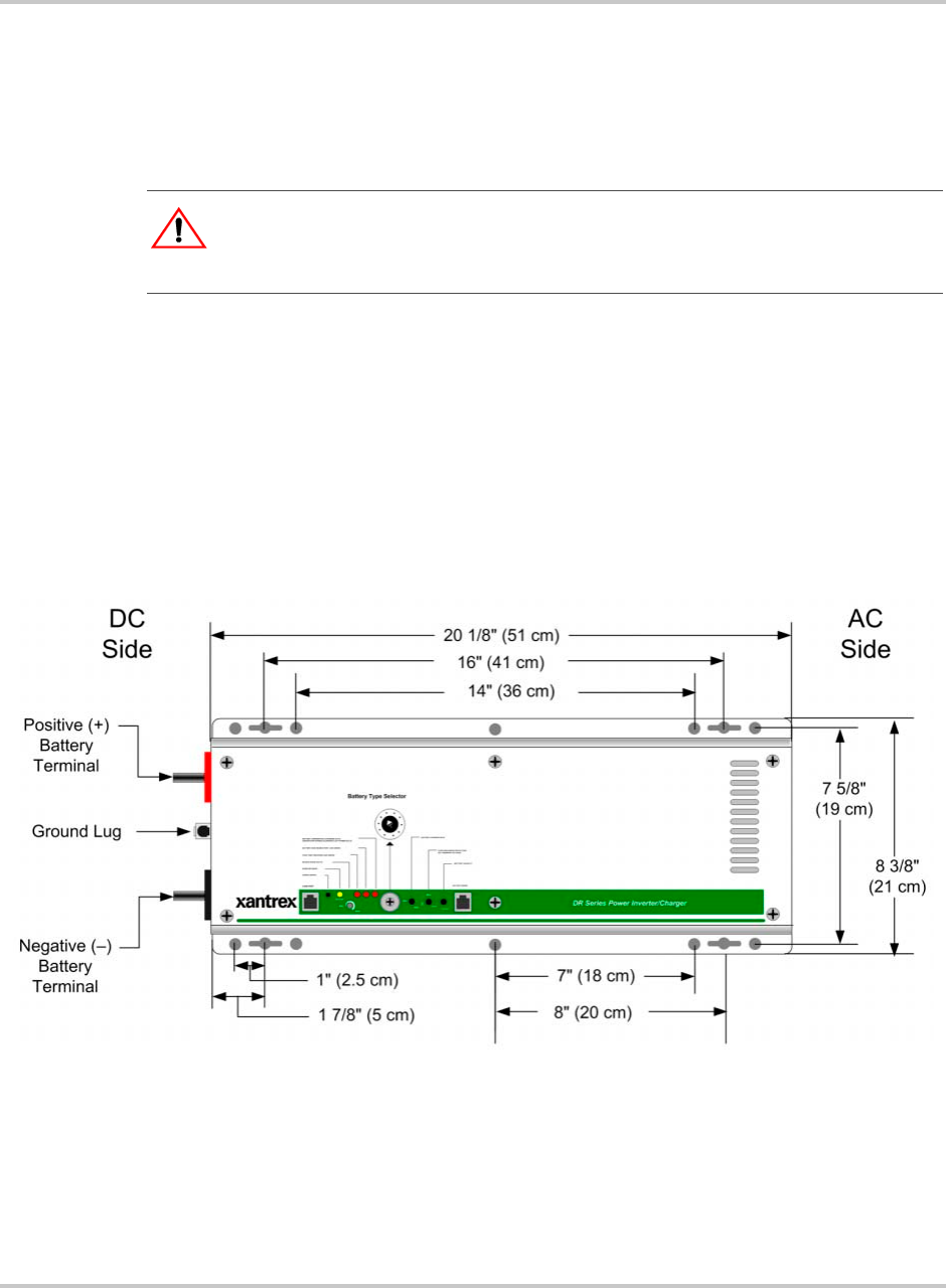
Inverter Mounting
The DR Series inverter can weigh as much as 45 lb. (20.4 kg). Wallboard is not
strong enough to support its weight so additional support must be used or added.
The inverter can be mounted directly to the wall studs if the wall studs are 16"
apart. If not, then 2x4’s or plywood can be used.
To secure the DR Inverter to the wall studs:
1. Locate the studs and mark their location on the wall.
2. Measure the desired height from the floor for the inverter to be mounted.
3. Using a level, run a horizontal line. The length of the line must span at least
three studs.
4. Using the dimensions illustrated in Figure 2-6, drill mounting holes into the
center of the studs for the inverter.
5. Secure the inverter to the studs using ¼ x 1½ inch lag bolts and washers.
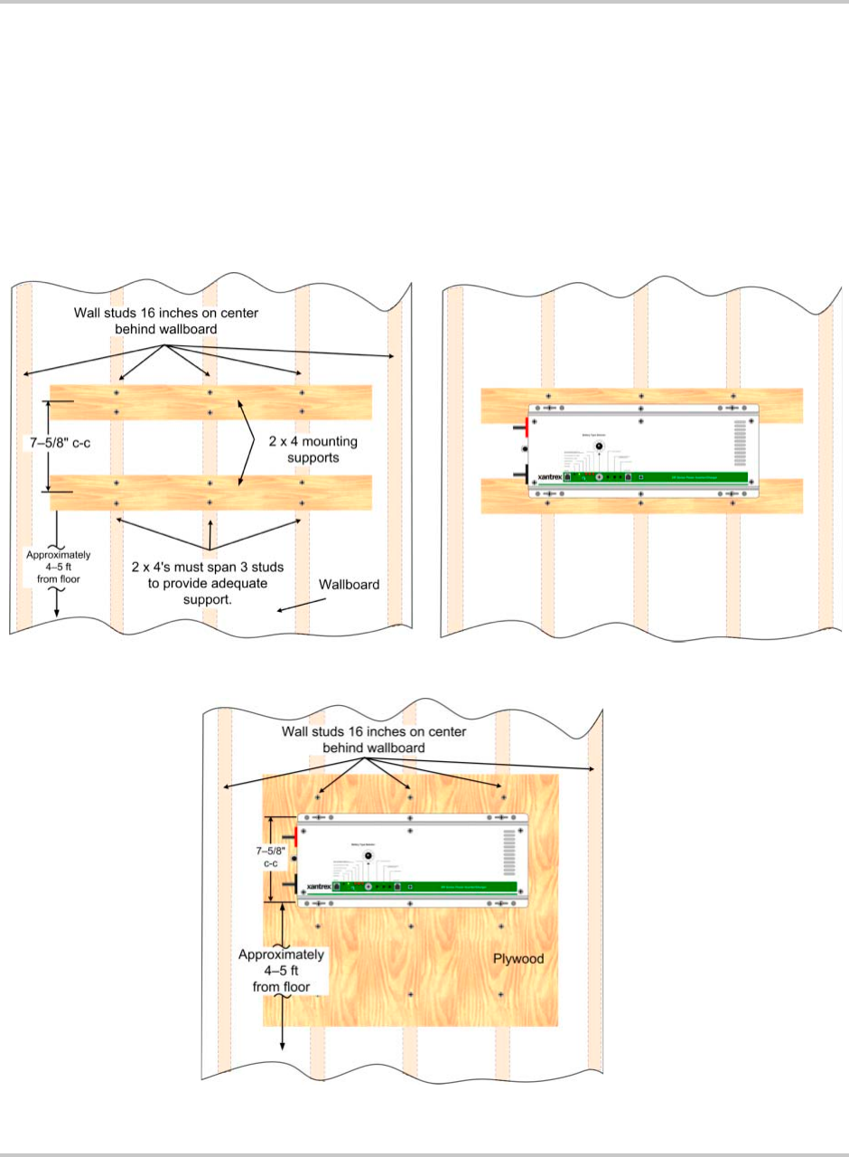
To secure the DR Inverter to the mounting location using 2 x 4’s or plywood:
1. Repeat steps 1 through 3 above.
2. Place a pre-cut 2 x 4 (flat side against the wall) on the marked location and
drill pilot holes through the 2 x 4’s and studs.
WARNING: Personal Injury
Use appropriate lifting techniques. Have extra people on hand to assist in lifting the
inverter into position while it is being secured.
Figure 2-6
Dimensions (not to scale)
Installation
2–12 975-0012-01-02 Rev A
3. Secure the 2 x 4 with #10 wood screws (length to penetrate 1½ inches into the
studs) as shown in Figure 2-7.
4. Measure 7 5/8" from the center of the first 2 x 4 and draw another level line.
Place the center of the second 2 x 4 over this line and secure to the wall as
described in Step 5.
5. Using the dimensions illustrated in Figure 2-6, drill mounting holes into the
center of the 2 x 4’s for the inverter.
6. Secure the inverter to the 2 x 4’s using ¼ x 1½ inch lag bolts and washers.
Figure 2-7
Suggested Mounting Method
Figure 2-8
Mounting on Plywood
Ensure the plywood spans
across a minimum of three wall
studs for adequate support.

DC Wiring
975-0012-01-02 Rev A 2–13
DC Wiring
This section describes the DC wiring requirements and how to make the
connections. It provides the required cable and wire sizes, recommended lengths
for cables, and disconnect/circuit breaker requirements.
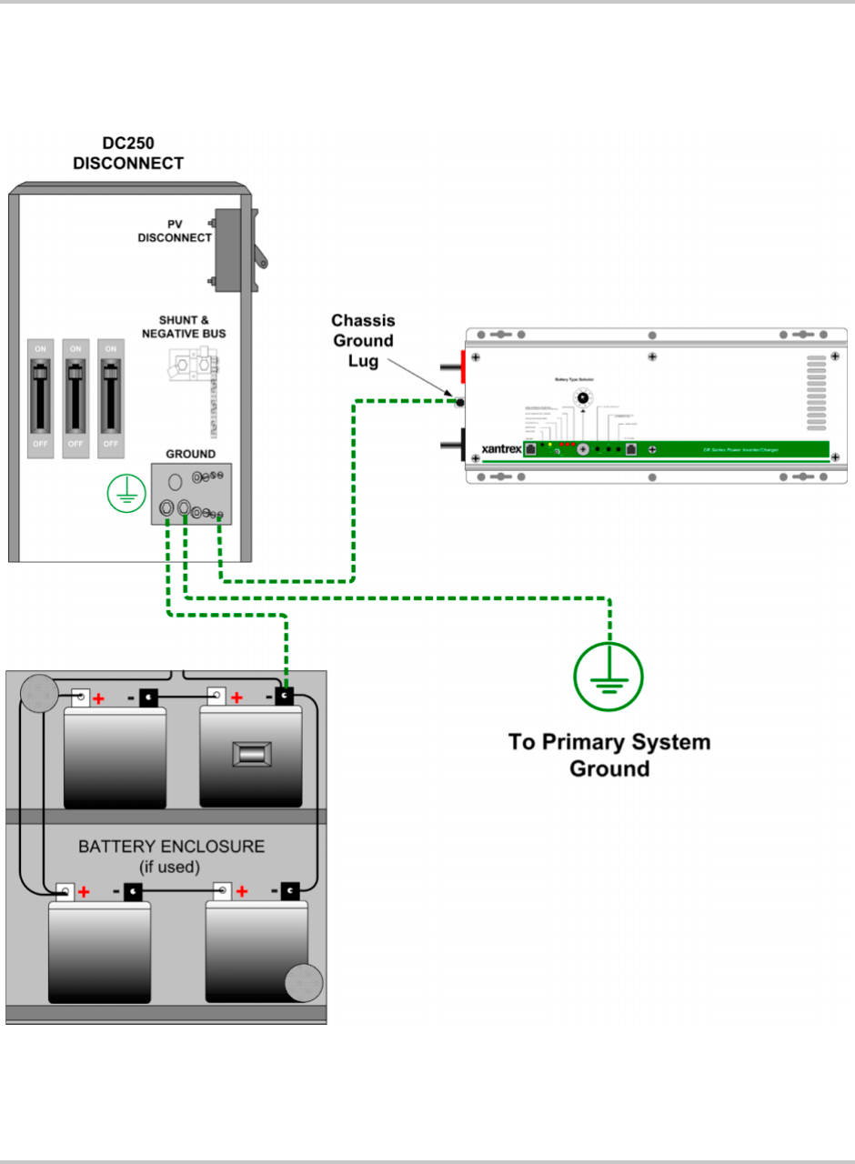
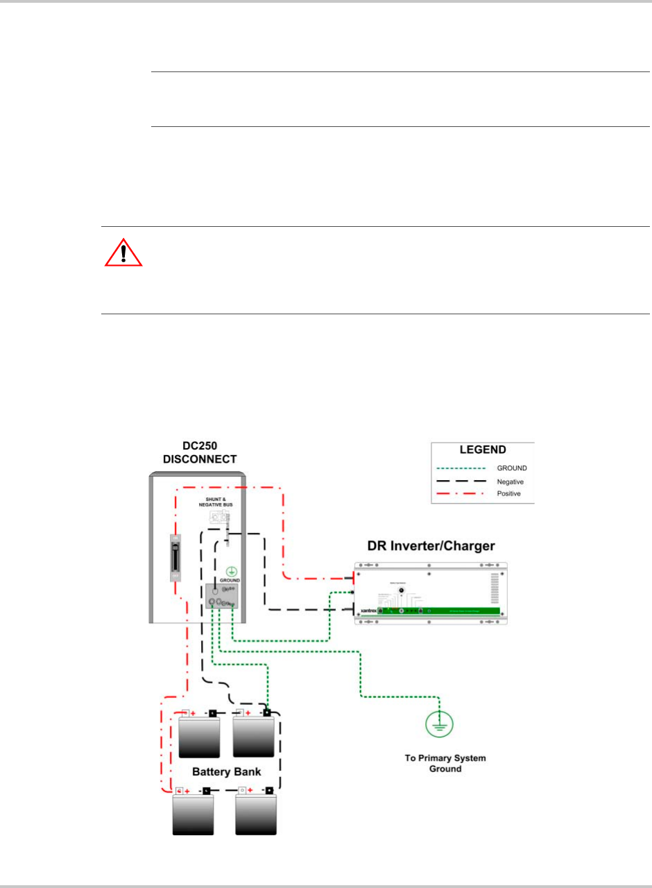
DC Circuit Grounding
Grounding is an important part of the system installation and must be performed
correctly to ensure safe operation of the equipment. Grounding requirements vary
by country and application. Consult the NEC for specific requirements.
The ground conductor should be sized appropriately for the over-current
protection device being used and according to NEC 250-95 (Ninth Edition)
(see Table 2-2 below for a portion of the NEC code).
General DC Grounding Requirements
This product is intended to be installed as part of a permanently grounded
electrical system per the National Electric Code ANSI/NFPA 70 (current edition).
This is the single point earth ground for the inverter system.
To ground the DC circuits:
1. Connect the negative (-) terminal of the battery bank to an appropriately sized
conductor and connect it to the ground bus in the DC Disconnect.
2. Connect an appropriately sized conductor to the Ground bus in the DC
Disconnect and connect it to the primary system ground.
The system ground is the same ground used by the AC side of the system.
Table 2-2
Safety Ground Conductor Size
Size of Over-current Device
Protecting the Conductor
Minimum Size of the Copper
Ground Wire
30 or 60 amp #10 AWG
100 amp #8 AWG
200 amp #6 AWG
300 amp #4 AWG
400 amp #3 AWG
Installation
2–14 975-0012-01-02 Rev A
Figure 2-9
DC Grounding

DC Wiring
975-0012-01-02 Rev A 2–15
Batteries
The DR Inverter can support either 12-volt battery banks or 24-volt battery banks.
Before proceeding, ensure you have the appropriate sized batteries for this
inverter.
Battery Types
Batteries are available in different sizes, amp-hour ratings, voltage, liquid or gel,
vented or non-vented, chemistries, etc. They are also available for starting
applications (such as an automobile starting battery) and deep discharge
applications. Only the deep discharge types are recommended for inverter
applications. Choose the batteries best suited for the inverter installation and cost.
Use only the same battery type for all batteries in the bank. For best performance,
all batteries should be from the same lot and date. This information is usually
printed on a label located on the battery.
Additional information regarding batteries can be found in the Appendix B,
“Battery Information”.
Battery Bank Sizing
The size of the battery bank determines how long the AC loads will operate in a
backup mode without utility power. The larger the battery bank, the longer the run
time. Size the battery bank to the AC load requirements and length of time
required to run from the batteries. In general, the battery bank should not be
discharged more than 50%. Additional DC charging devices such as solar, wind,
hydro, etc., can provide longer run times by recharging the batteries in the absence
of AC utility or generator power.
Additional details on estimating battery bank size and capacity can be found in
“Battery Bank Sizing” on page B–4.
Battery Configuration
The battery bank must be wired to match the inverter’s DC input voltage
specifications (12 Vdc, 24 Vdc, or 48 Vdc). In addition, the batteries can be wired
to provide additional run time. The various wiring configurations are:
• SERIES - Wiring batteries in series increases the total bank output voltage (to
match the inverter’s DC requirements).
• PARALLEL - Wiring the batteries in parallel increases the total run time the
batteries can operate the AC loads.
• SERIES-PARALLEL - Series-parallel configurations increase both the
battery voltage (to match the inverter’s DC requirements) and run-time for
operating the AC loads.
For additional information on how to wire these battery-bank configurations, see
“Battery Configurations” on page B–8.
Installation
2–16 975-0012-01-02 Rev A
Battery Cable Sizing
Proper cable sizing (diameter and length) is critical to the safe and efficient
operation of an inverter system. Larger diameter cables (smaller AWG number)
have less voltage drop and are, therefore, more efficient when transferring power
to and from the batteries. If a cable is undersized (diameter too small), it could
potentially overheat, creating a fire hazard.
Cable length is another important factor. Runs should be kept as short as practical.
Longer cable runs increase resistance, thus lowering the overall efficiency of the
system. This is especially true in lower voltage systems (i.e., 12 Vdc) where,
depending upon the length of the cable run, it may be necessary to oversize the
diameter of the wire, or parallel (double) the cables.
Table 2-3 provides recommended minimum cable sizes for various cable lengths
and inverter amperages. These recommendations may not meet all local or NEC
requirements.
Important:
Only use copper cables. Always use a properly sized cable and length rated
for the amperage of the inverter and batteries.
WARNING: Fire Hazard
Undersized cables can overheat and melt, creating a fire hazard when subjected to heavy
(peak) loads.
Important:
Run the positive and negative battery cables as close to each other as
possible by taping them together. This reduces the effects of inductance and produces a
better waveform thus increasing efficiency. See Xantrex Technical Note 008 on the
Xantrex website for additional information on Battery Cable Inductance.
Table 2-3
Minimum Recommended Battery Cable Size versus Length
Inverter
Model
Typical
Amperage 1 to 3 feet (one-way) 3 to 5 feet (one-way) 5 to 10 feet (one-way)
DR1512 150 A #2/0 AWG (67.4 mm2) #2/0 AWG (67.4 mm2) #4/0 AWG (107 mm2)
DR2412 240 A #4/0 AWG (107 mm2) #2/0 AWG (67.4 mm2) #2/0 AWG (67.4 mm2)
DR1524 75 A #2/0 AWG (67.4 mm2) #2/0 AWG (67.4 mm2) #2/0 AWG (67.4 mm2)
DR2424 120 A #2/0 AWG (67.4 mm2) #4/0 AWG (107 mm2) #4/0 AWG (107 mm2)
DR3624 180 A #4/0 AWG (107 mm2) #4/0 AWG (107 mm2) #4/0 AWG (107 mm2)
Important:
If the system includes a large battery bank or large DC source (such as a
micro-hydroelectric plant or wind generator), increasing the size of the cables and
disconnects will greatly reduce the number of nuisance outages associated with breaker
tripping and open fuses.

DC Wiring
975-0012-01-02 Rev A 2–17
DC Disconnect and Over-current Protection
For safety and to comply with regulations, battery over-current protection is
required. Fuses and disconnects must be sized to protect the wiring in the system
and are required to open before the wire reaches its maximum current carrying
capability.
The National Electrical Code (NEC) requires both over-current protection and a
disconnect switch for residential and commercial electrical systems. These items
are not supplied as part of the inverter. However, Xantrex offers a DC rated, ETL
Listed, circuit breaker disconnect module specifically designed for use with
Xantrex™ inverters to meet NEC compliance. Two amperage ratings are
available: a DC250 (250 amps) and a DC175 (175 amps) in either single or dual
breaker configurations for single- or dual-inverter installations.
Some installations may not require conduit or a disconnect device, although
over-current protection is still required. Xantrex offers a fuse block (TFB)
providing the code required inverter over-current protection for these applications.
Refer to the table below for the proper size disconnect device for specific cable
diameters.
Important:
Xantrex™ DC disconnects are not designed to accept doubled
(paralleled) cables which may be required for long cable runs. Also, the plastic
red and black covers on the DC inverter inputs are not designed to accommodate
dual cables. If dual cables are used, the optional conduit box (DRCB) must be
used.
Table 2-4
Battery Cable to Maximum Breaker/Fuse Size
Cable Size
Required Rating in Conduit
Maximum Breaker
Size
Rating in “Free
Air”
Maximum Fuse
Size
#2 AWG 115 amps max N/A 170 amps max TFB200
#2/0 AWG 175 amps max DC175 265 amps max TFB300
#4/0 AWG 250 amps max DC250 360 amps max TFB400
Important:
The NEC allows rounding to the next standard fuse size from the cable
rating (i.e., 150 amp cable size rounds up to a standard 175 amp size). The term “free air”
is defined by the NEC as cabling that is not enclosed in a conduit or a raceway. Cables
enclosed in conduit or raceways have substantially lower continuous current carrying
ability due to heating factors.
Installation
2–18 975-0012-01-02 Rev A
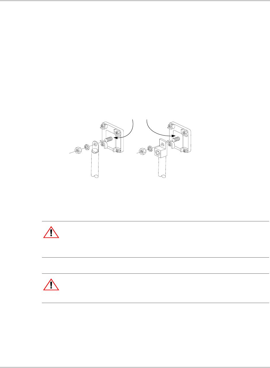
Battery Cable Connections
Battery cables must have crimped (or preferably, soldered and crimped) copper
compression lugs unless aluminum mechanical lugs are used. Soldered
connections alone are not acceptable. High quality, UL-listed battery cables are
available from Xantrex in an assortment of lengths: 1½ to 10 feet, and in
#2/0 AWG or #4/0 AWG sizes. These cables are color-coded with pressure
crimped, sealed ring terminals.
Figure 2-10 illustrates the proper method to connect the battery cables to the DR
Inverter’s DC terminals.
Figure 2-10
Battery Cable Connections
CAUTION: Equipment Damage
The inverter is not reverse polarity protected. Reversing the battery polarity on the DC
input connections will cause permanent damage to the inverter which is not covered under
warranty. Always check polarity before making connections to the inverter.
WARNING: Shock Hazard
Ensure the inverter is off before disconnecting the battery cables, and that AC power is
disconnected from the inverter input.
2/0 Copper Compression Lug 2/0 Aluminum Mechanical Lug
Do not place anything
between battery cable lug
and terminal surface.
Assemble exactly as shown.
DC Wiring
975-0012-01-02 Rev A 2–19
Connecting the Battery Bank to the Inverter
Follow the procedure below to connect the battery bank to the inverter.
To connect the battery bank to the inverter:
1. Determine the correct size battery cable to use for installation from Table 2-3
on page 2–16.
2. Determine the correct size disconnect/fuse for installation from Table 2-4 on
page 2–17.
3. Color code the cables with tape or heat shrink tubing. The standard colors are
red for positive (+) and black for negative (–). (NEC requires white for the
negative conductors.)
4. Connect the negative (–) cable to the battery’s negative terminal (torque to
manufacturer’s recommendations).
5. Install the over-current device (fuse or circuit breaker) between the battery’s
positive terminal and the inverter’s positive terminal (as close to the batteries
as possible).
6. Connect the (short) positive cable to the battery’s positive terminal (torque to
manufacturer’s recommendations).
7. Ensure the correct polarity of the cables with a DC voltmeter (DVM).
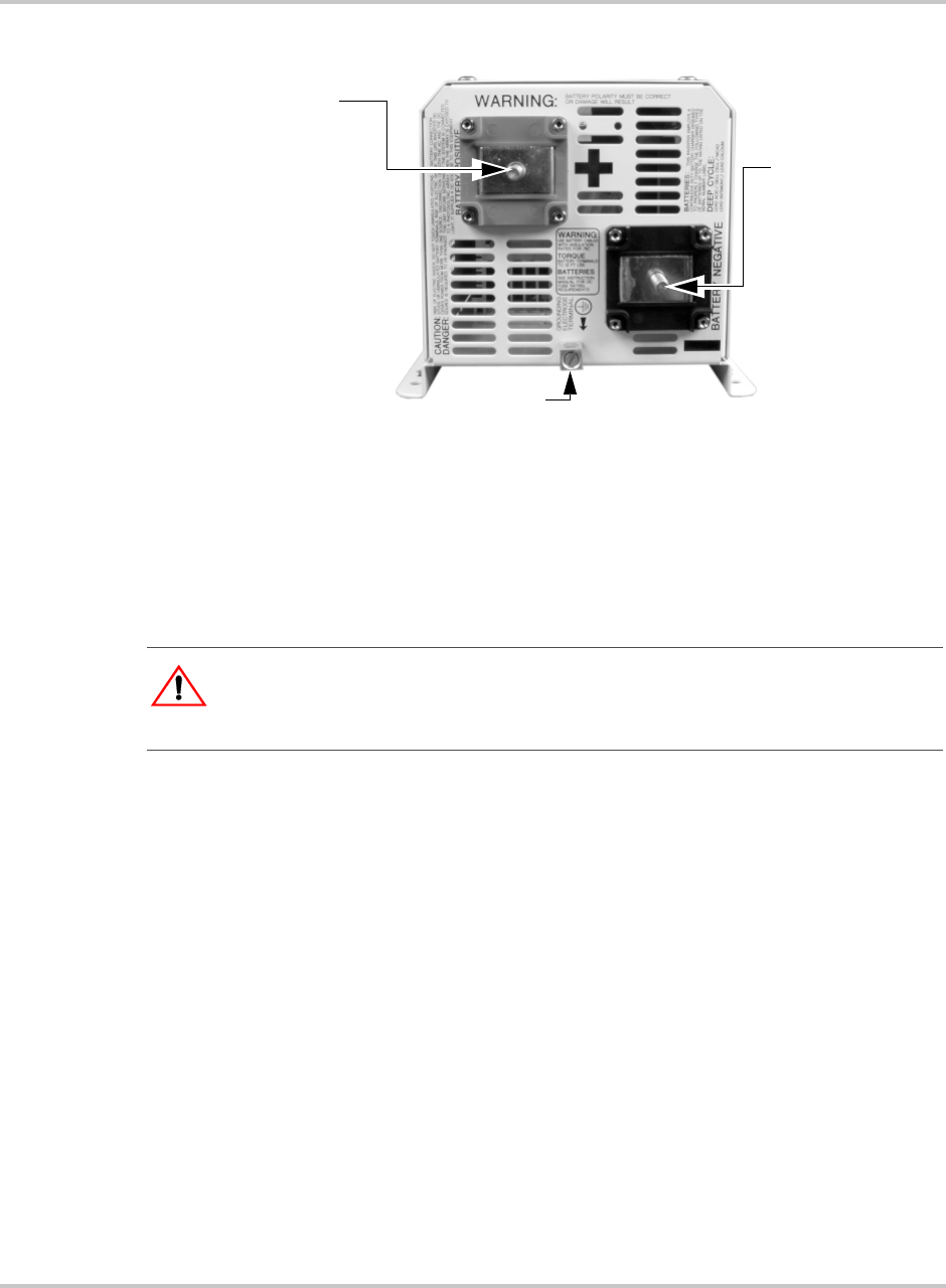
Figure 2-11
DC Terminals on the DR Inverter
Ground Lug
Negative (–)
Battery Terminal
Positive (+)
Battery Terminal
Torque the
Positive (+)
Battery terminal to
10-15 ft-lbs
(13.6 to 20.3 nm)
Torque value for
the Ground Lug
is 10-15 in-lbs
(1.1 to 1.7 nm)
Torque the
Negative (–)
Battery terminal to
10-15 ft-lbs
(13.6 to 20.3 nm)
:
WARNING: Shock Hazard
Ensure the inverter is off before connecting or disconnecting the battery cables and that all
AC power is disconnected from the inverter’s inputs.
Installation
2–20 975-0012-01-02 Rev A
8. Observing battery polarity, connect the positive battery cable (from the
over-current device) to the inverter’s positive terminal.
9. Observing battery polarity, connect the negative battery cable to the inverter’s
negative terminal.
10. Use an insulated ½ inch wrench or socket to tighten the 5/16 SAE nuts to
10-15 ft-lb (13.6 to 20.3 nm) for each inverter input terminal.
11. Apply antioxidant paste to the battery and inverter terminals.
12. Install the battery terminal connection covers (red for positive, black for
negative) over the inverter’s DC terminals and secure with the screws and
washers provided.
Important:
The next step may cause a small spark and snapping sound when
connecting the cable to the inverter. This is normal, and is caused by the inverter’s
capacitors charging up.
: Equip
CAUTION: Equipment Damage
Do not put anything between the cable ring terminal and the flat metal part of the terminal.
overheating of the terminal may occur. Do not apply any type of antioxidant paste until
after the battery cable wiring is tightened.
Figure 2-12
Connecting the Battery Bank to the DR Inverter/Charger
DC Wiring
975-0012-01-02 Rev A 2–21
Installing a Battery Temperature Sensor
A battery temperature sensor (BTS) option can easily be installed in the system to
ensure proper charging of the batteries based on temperature. Installing a BTS
extends battery life by preventing overcharging in warm temperatures and
undercharging in cold temperatures.
To install the Battery Temperature Sensor:
1. Run the battery temperature sensor wire in the DC conduit (if used) and route
the RJ11 connector end to the BATTERY SENSE port located on the front of
the inverter.
2. Secure the sensor to one of the batteries located in the center of the battery
pack.
Figure 2-13
Battery Temperature Sensor (BTS) RJ11 Jack Location
Figure 2-14
Connecting the BTS to the DR Inverter
Battery Sense
(RJ11) port
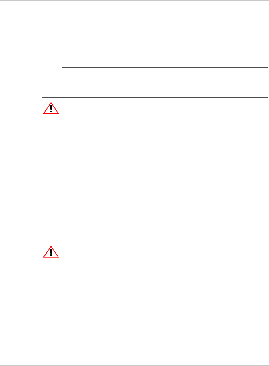
Installation
2–22 975-0012-01-02 Rev A
AC Wiring
This section describes the AC wiring requirements and how to make the
connections. It provides the required wire sizes, recommended lengths for
conductors, and disconnect/circuit breaker requirements.
AC Distribution Panel (Sub-panel) Mounting and Conduit Installation
1. Determine the location of the sub-panel and install it according to the
manufacturer’s directions.
2. Install the AC conduit between the sub-panel (output) and inverter.
3. Install conduit between the inverter (input) and the main breaker box.
4. Determine which circuits require backup. Install the appropriate circuit
breakers into the sub-panel.
5. Install an appropriately sized circuit breaker (30 amp maximum) in the
sub-panel. This will later be wired to the inverter’s output. If two inverters are
being used in a stacked configuration, install a double-pole circuit breaker for
240 Vac service.
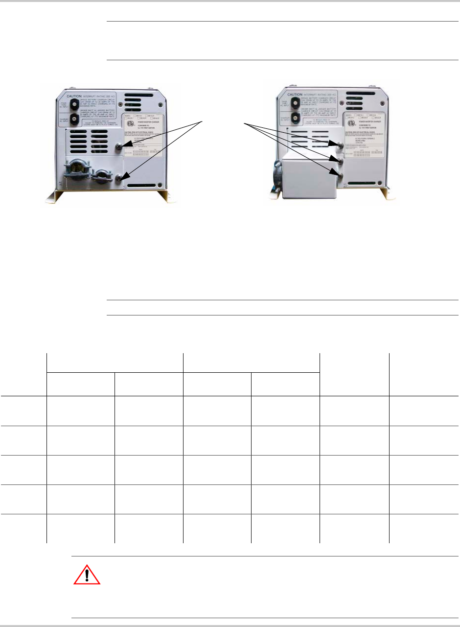
Accessing the AC Terminals
All AC wiring connects to the terminal block located on the right-hand side of the
inverter.
To make the AC connections to the inverter:
1. To access the terminal block, remove the side cover panels (if installed) by
removing the two (or three) Phillips screws. Units are shipped without the
covers installed (packed in a small plastic bag with additional hardware).
2. Locate the AC input and output terminals on the block. Refer to Figure 2-15
on page 2–23.
Important:
The installation of sub-panels and wiring should be performed by a
qualified person or a licensed electrician following all local and NEC codes.
WARNING: Shock Hazard
Disconnect the power from the utility’s main breaker box before proceeding.
CAUTION: Equipment Damage
The inverter’s AC output must never be wired to the utility or generator output. This will
cause severe damage to the inverter which is not covered under warranty.
AC Wiring
975-0012-01-02 Rev A 2–23
Before wiring the input of the inverter, refer to Table 2-5 below for the minimum
recommended wire size.
Important:
The lower AC cover varies depending on the model. DR24XX and
DR36XX models are equipped with a conduit box and not a plate. The conduit box is
required for the larger diameter wire providing ample bending radius.
Figure 2-15
AC Side Cover Panels
Screws
Standard Cover Plate High Power Conduit Box
DR15XX DR24XX and DR36XX models
Important:
Refer to the NEC for actual wire sizes for specific installations.
Table 2-5
Minimum Recommended Wire Size, Torque Values (Input and Output), and Maximum Output
Breaker Size
Inverter
Model
AC Input AC Output Torque Value
for Terminal
Connections
Maximum
Output
Breaker Size120 Vac 220-240 Vac 120 Vac 220-240 Vac
DR1512 #8 or 6 AWG #10 AWG #10 AWG #16 AWG 16 in-lbs
(1.8 nm)
30 amps AC
DR2412 #6 AWG #10 AWG #10 AWG #14 AWG 16 in-lbs
(1.8 nm)
30 amps AC
DR1524 #8 or 6 AWG #10 AWG #10 AWG #16 AWG 16 in-lbs
(1.8 nm)
30 amps AC
DR2424 #6 AWG #10 AWG #10 AWG #14 AWG 16 in-lbs
(1.8 nm)
30 amps AC
DR3624 #6 AWG Not Available #8 AWG Not Available 16 in-lbs
(1.8 nm)
30 amps AC
WARNING: Fire Hazard
To reduce the risk of fire, connect only to a circuit provided with the maximum
branch-circuit overcurrent protection noted above in accordance with the National
Electrical Code, ANSI/FFPA70.
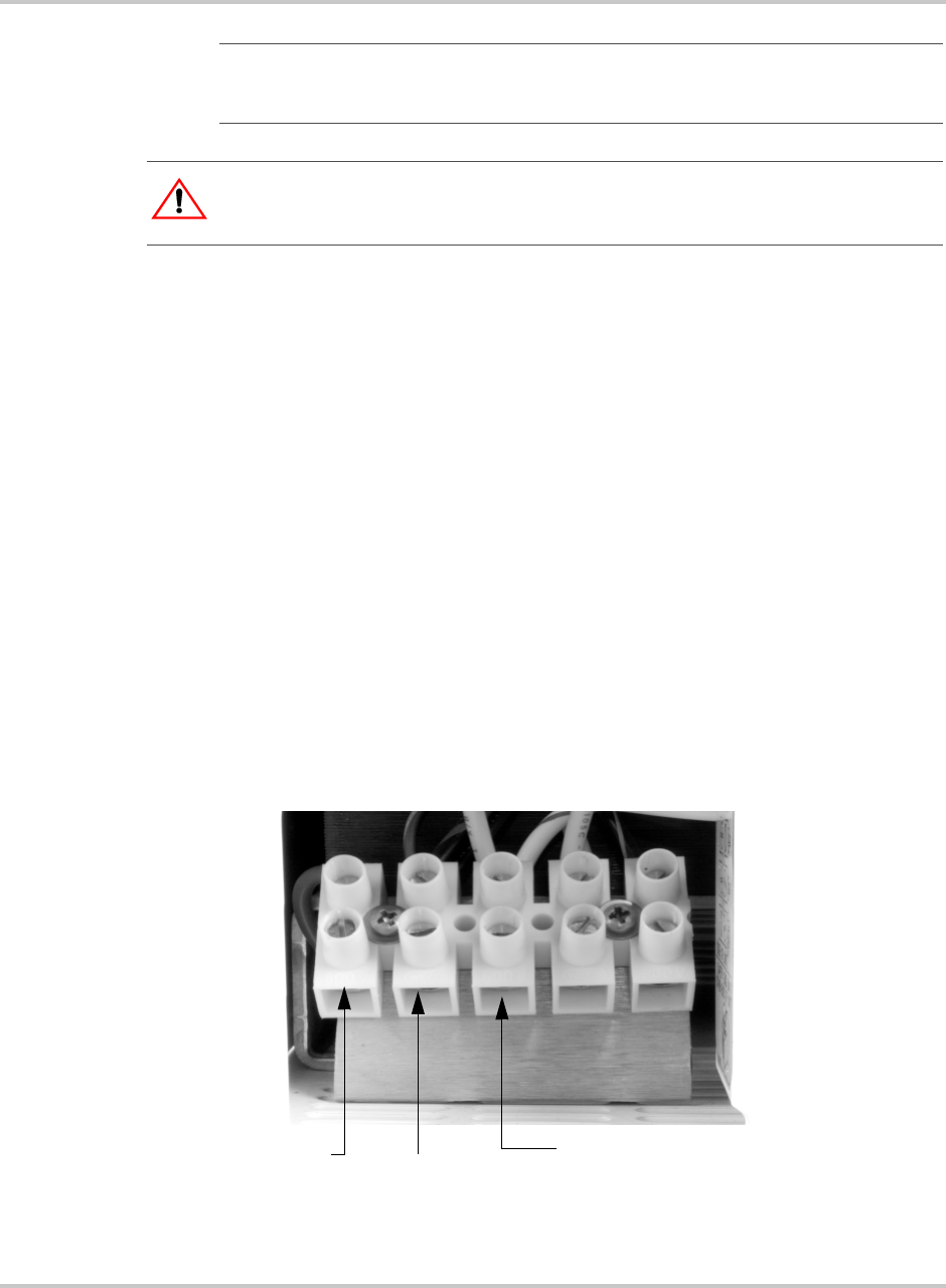
Installation
2–24 975-0012-01-02 Rev A
To connect the AC Input to the Inverter:
1. Disconnect the main breaker at the main electrical service panel (if used) or
disconnect the AC generator.
2. Install an appropriately sized circuit breaker in the electrical service panel.
This will serve as both an AC disconnect and over-current protection. If using
a generator only, use the circuit breaker in the generator.
3. Feed the HOT, NEUTRAL, and GROUND wires (using conduit) from the
inverter to the AC source. Leave several inches of extra wire at each end.
4. Make the connections to the inverter first. Wiring to the AC source is
performed after all connections have been made in the inverter.
a) Connect the GROUND (green) wire to the inverter’s AC GROUND
terminal.
b) Connect the NEUTRAL (white) wire from the AC source to the inverter’s
NEUTRAL INPUT terminal.
c) Connect the HOT (black) wire from the AC source to the inverter’s AC
HOT INPUT terminal.
5. Torque all connections to 16 in-lbs (1.8 nm).
Important:
The U.S. requires conduit be used in this type of installation. Refer to the
NEC and local codes. Conduit fittings can be replaced with strain reliefs where code
permits.
WARNING: Shock Hazard
Disconnect the battery cables from the inverter if they are already connected.
Figure 2-16
AC Terminals for AC Input to the Inverter
GROUND HOT IN
NEUTRAL IN
Torque the
terminal
connections to
16 in-lbs (1.8 nm)
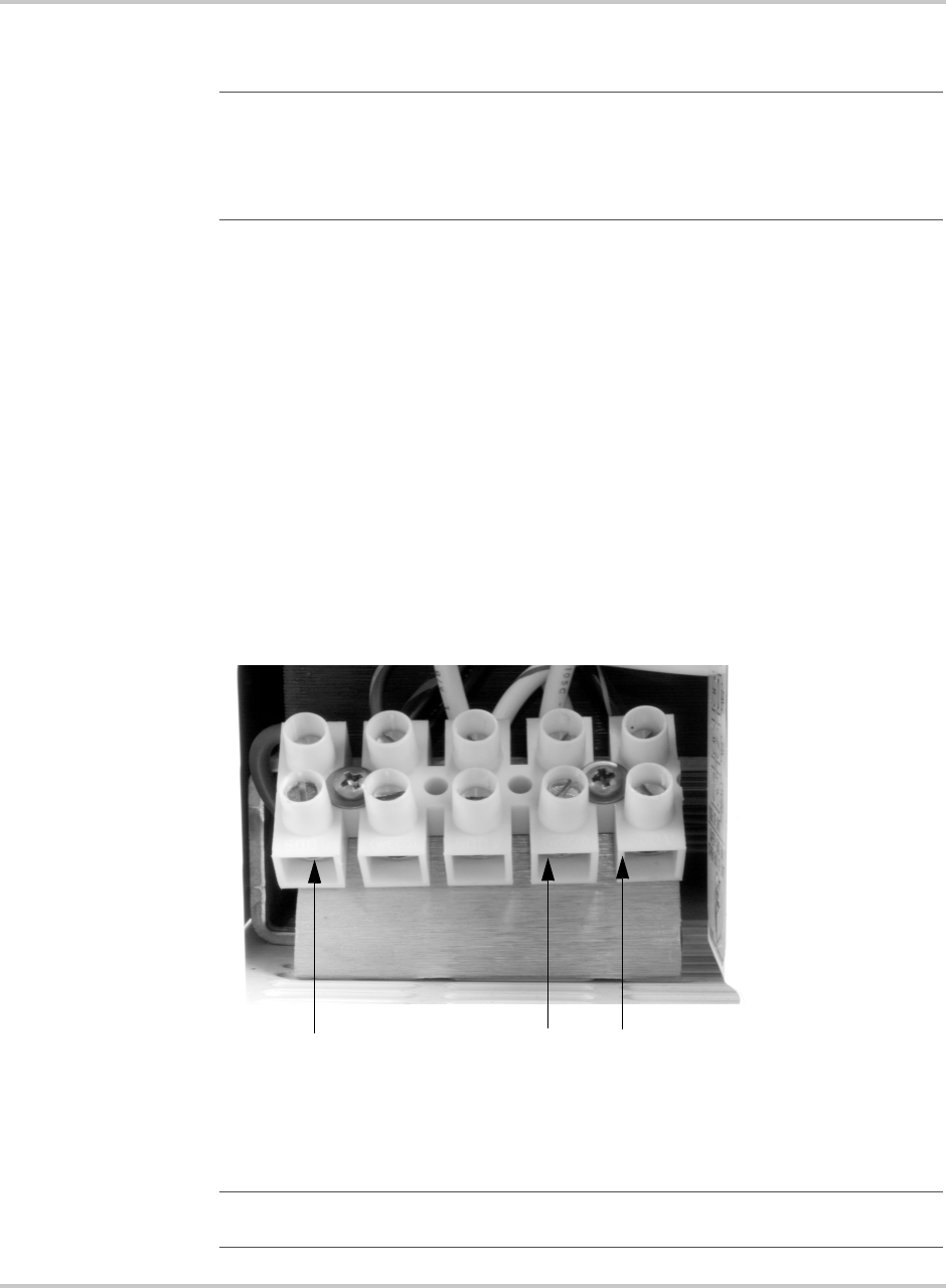
AC Wiring
975-0012-01-02 Rev A 2–25
AC Output Wiring to the AC Distribution Panel (Sub-panel)
To connect the AC output wiring to the sub-panel:
1. Connect the GROUND wire to the inverter’s AC GROUND chassis terminal.
Connect the other end of this wire to the GROUND bus in the sub-panel.
2. Connect the NEUTRAL (white) wire to the inverter’s NEUTRAL OUTPUT
terminal. Connect the other end of this wire to the NEUTRAL bus in the
sub-panel.
3. Connect the HOT (black) wire to the inverter’s terminal labeled AC HOT
OUTPUT. Connect the other end of this wire to the sub-panel’s input circuit
breaker.
4. Torque all inverter terminal block connections to 16 in-lbs (1.8 nm).
5. Refer to the sub-panel manufacturer’s specifications for wire torque
requirements to sub-panel terminals.
Important:
The ground and neutral must be bonded at one place, and only one place, in
the system. If the generator is the main source of power, (i.e., no utility grid power) then
the neutral and ground connections are bonded at the generator. If the generator is acting
as a backup for the utility grid, then the bond should be at the main utility service entrance
box. In this case, ensure that no bond exists at the generator output.
Figure 2-17
AC Terminals for AC output to the Sub-panel
Important:
The two neutral connections (input and output) are common to one another
and may be used in any combination.
GROUND HOT
OUT
NEUTRAL
OUT
Torque the terminal
connections to
16 in-lbs (1.8 nm)
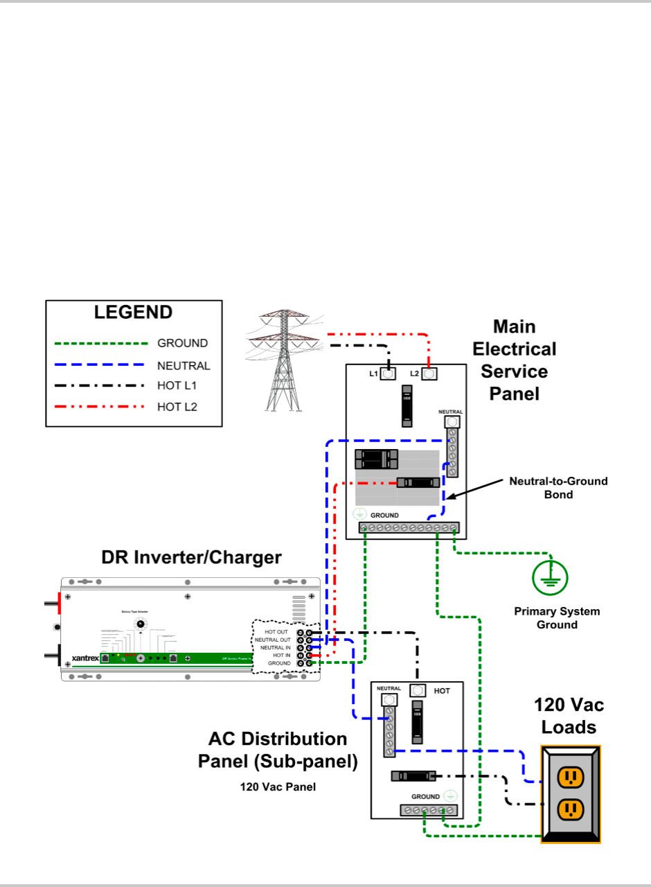
Installation
2–26 975-0012-01-02 Rev A
The following diagrams illustrate the AC wiring for the following basic
120/240 Vac scenarios. Consult your system design for other possible
configurations.
• On-Grid Application (See Figure 2-18)
• On-Grid using with a generator Backup (See Figure 2-19)
• On-Grid Dual-Inverter Application (See Figure 2-20)
• Off Grid Application using a 120 Vac Generator (See Figure 2-21)
• Off-Grid Application using a 240 Vac Generator (See Figure 2-22)
• Off-Grid Dual-Inverter Application (see Figure 2-23)
AC Input Wiring - On-Grid Applications
Follow the example below to complete the wiring for an on-grid application.
Figure 2-18
AC Wiring- On-Grid Application
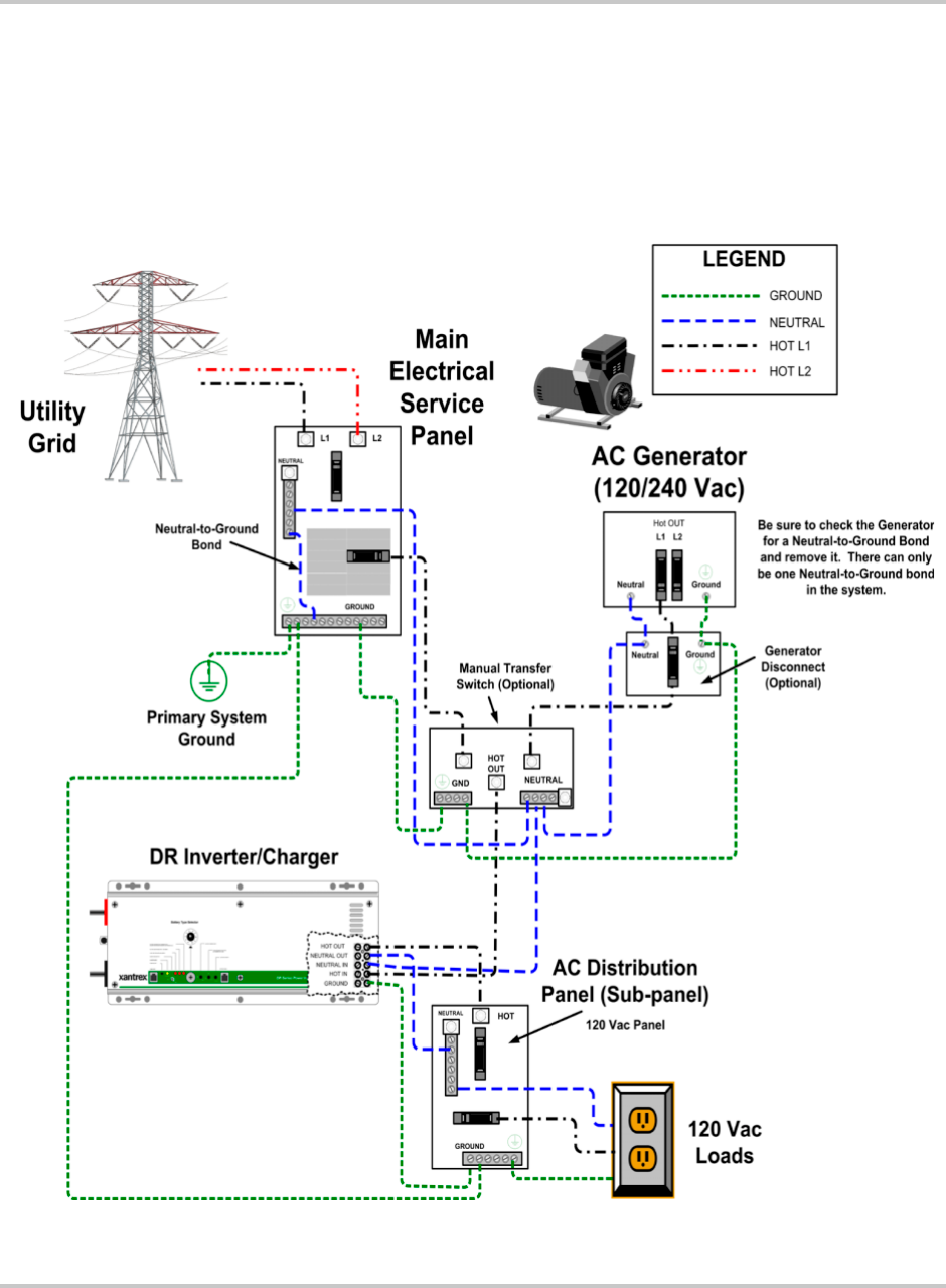
AC Wiring
975-0012-01-02 Rev A 2–27
AC Input Wiring using a Generator in an On-Grid Application
If a generator is used as a backup for the utility, then a manual transfer switch
must be added to provide a means to switch the generator power to the inverter’s
inputs. The generator can be used during extended outages to recharge the
batteries and provide pass through power for the loads. Start and stop the
generator manually using the generator’s pull-cord, ON/OFF switch, etc.
Figure 2-19
AC Wiring using a Generator - On-Grid Application
Installation
2–28 975-0012-01-02 Rev A
AC Input Wiring - Off-Grid Applications using a 120 Vac Generator
Follow the example below to complete the wiring for an off-grid application.
Figure 2-20
AC Wiring using a 120 Vac Generator - Off-Grid Application
AC Wiring
975-0012-01-02 Rev A 2–29
AC Input Wiring - Off-Grid Applications using a 240 Vac Generator for
120 Vac Loads
Follow the example below to complete the wiring for an off-grid application.
Figure 2-21
AC Wiring using a 240 Vac Generator with 120 Vac Loads only- Off-Grid Application

Installation
2–30 975-0012-01-02 Rev A
Series Stacking (120 Vac/60 Hz Models only)
This COM port allows two DR Inverters (120 Vac/60 Hz models only) to be used
in the same system in a “SERIES” configuration to operate 240 Vac loads. Series
stacking can also be used to connect to 240 Vac only power systems providing
both 120 and 240 Vac outputs. A series stacking interface cable (DRI) is required
to connect the series stacking port of the inverters.
In this mode, one of the inverters will function as the “primary” and the other
inverter becomes the “secondary.” The first unit switched ON becomes the
primary and ensures the secondary’s output is 180 degrees out of phase for
240 Vac operation. Both units can charge the batteries or provide battery backup
power during a utility outage.
The following illustrations provide a general overview of AC configurations using
stacked inverters. Detailed wiring and operating instructions are provided with the
DRI interface kit available from Xantrex Technology Inc.
The following diagrams illustrate the AC Wiring for a basic On-Grid and Off-Grid
application.
AC Wiring
975-0012-01-02 Rev A 2–31
Figure 2-22
AC Wiring for dual-inverters - On-Grid Application (120 Vac models only)
Installation
2–32 975-0012-01-02 Rev A
Figure 2-23
Wiring for dual-inverters - On-Grid Application (120 Vac models only)
3Operation
Chapter 3, “Operation” contains information about how to operate the
DR Inverter/Charger.
Operation
3–2 975-0012-01-02 Rev A
Front Panel Controls and Indicators
All operating controls, indicators and sense connectors are located on the front
panel of the unit. The controls are easily accessible, and the LEDs provide
inverter/charger status at a glance.
POWER ON/OFF Switch
The POWER ON/OFF control is a momentary contact switch that turns the
inverter/charger ON or OFF by pressing it once. When the inverter is first
connected to the batteries, it will run through a self test consisting of flashing the
LEDs in sequence, operating the cooling fan momentarily and switching the
transfer relay three times. Once the self test has successfully completed, the
POWER ON/OFF switch is activated. Pressing the switch once turns the inverter
ON. Another press turns the inverter OFF.
Figure 3-1
Front Panel Controls and Indicators
COM Port
Battery Sense Port
POWER ON/OFF
Inverter Mode Controls
(Search Watts)
Inverter Mode Indicator
Battery Type Selector
Battery Charge Control
LED Status
Indicators

Front Panel Controls and Indicators
975-0012-01-02 Rev A 3–3
Ports
There are two ports on the inverter/charger. Both ports are RJ11 type telephone
style connectors. One is used for connecting a remote control to the inverter. The
other is used for regulating the charger voltage based on the temperature of the
battery bank.
BATTERY SENSE Port
The BATTERY SENSE Port is used for connecting a battery temperature sensor
(BTS) to control the charging rate based on battery temperature. The sensor
should be taped onto the side of one of the batteries. The information received in
this port adjusts the charger’s output higher in cold temperatures, assuring the
batteries receive a full charge, and lowers it during warm temperatures, reducing
battery gassing and providing overcharge protection.
Refer to the Installation section for the BTS location on the battery.
COM Port
COM PORT (J1) is a dual function RJ11 (6-pin) connector. Its primary function is
to provide serial communications to an optional Xantrex™ remote control unit
(RC4 or RC8). The port also acts as a stacking interface control when two DR
Inverters are used in a series configuration. When two inverters are stacked, a
remote control cannot be used with either unit.
Remote Controls (RC8/RC4)
DR Inverter are designed to operate with either an RC8 or RC4 remote control
units. Both remotes incorporate a membrane switch with a single red LED display
combination to start and stop the inverter, as well as provide overall system
operating status.
•Solid - With AC line power present, the unit is charging the batteries while
directing AC to the load. With no AC line power present, the inverter is
running on the batteries and supplying AC to the load.
•Blinking Slow (1 to 3 flashes @ 1 second intervals) - The inverter is in search
mode (no load connected).
•Blinking Fast (3 to 5 flashes @ 1 second intervals) - The inverter is charging
the batteries.
•Flickering (3 to 5 flashes @ 1 second intervals) - The inverter has detected an
over-current error. The LED (and inverter) will turn OFF whenever an over-
current condition exceeds eight seconds.
Important:
The Battery Sense only adjusts charging voltage. It does not disable the
charger.
Operation
3–4 975-0012-01-02 Rev A
•Erratic Blinking (0 to 3 and 2 to 5 flashes @ 2 second intervals) - The
inverter has detected an error condition caused by overheating, low battery
voltage, or high battery voltage.
• OFF - The inverter is OFF.
The remote control must be connected prior to switching the inverter ON;
otherwise, the micro-controller will not recognize (or respond to) the remote. If
the remote is not recognized, switch the inverter OFF and then ON using the
inverter’s front panel POWER ON/OFF switch.
Stacking Interface
Whenever two DR Series inverters are used in a series (stacked) configuration,
one unit (primary) controls the other unit (secondary). Communication between
the two inverters is done via the COM port (J1). The first unit switched ON, using
its front panel POWER ON/OFF switch, becomes the controlling (primary)
inverter.
Controls
There are several controls on the inverter’s front panel that provide adjustments
for the battery charger, and AC output energy saving mode.
Battery Type Selector
The Battery Type Selector is a 10 position rotary switch used to set the inverter’s
charger for the proper Float and Bulk voltage levels. These levels are selected
depending on the type of batteries used.
There are also 2 positions (0 and 1) which allow the batteries to be equalized.
Equalizing batteries should only be done on liquid lead acid batteries and never on
gel batteries. Refer to the table below for the charge voltages in the various switch
positions. Consult the battery manufacturer for optimum battery voltage charging
settings.
Figure 3-2
Battery Type Selector Adjustment
Battery Type Selector Enlargement
(pointing to Setting 7)

Front Panel Controls and Indicators
975-0012-01-02 Rev A 3–5
See Important notes that follow.
Table 3-1
Battery Type Selector Switch Settings
Switch
Position Description
12-volt Models 24-volt Models Charge Function
Float
Voltage
Bulk/
Equalize*
Voltage
Float
Voltage
Bulk/
Equalize*
Voltage
Equalize Charge
Rate Equalize Time
0 Equalize 1 -
equalizes at a rate
equal to the
battery bank
capacity (in amp-
hours) divided by
40.
13.2 *15.0 26.4 *30.0 Battery Capacity
Setting (C/40)
6 hrs. minimum
12 hrs. maximum
1 Equalize 2 -
charges at a rate
set by the
BATTERY
CHARGER
RATE control.
13.2 *15.5 26.4 *31.0 Battery Charger
Rate Setting
(manual)
6 hrs. minimum
12 hrs. maximum
2 Deep Cell Lead
Acid 2
13.3 15.0 26.6 30.0 Provides an additional Float and Bulk
settings for deep cycle, lead acid batteries.
Refer to the battery manufacturer’s
recommendation for Float and Bulk
settings.
3 Not Specified 13.6 14.3 27.2 28.6 Provides an additional setting of Bulk and
Float voltages.
4 Gel Cel 2 13.7 14.4 27.4 28.8 Recommended for gel cell batteries that
specify high float voltages. Check with the
battery’s manufacturer.
5 Gel Cell 1 13.5 14.1 27.0 28.2 Typical gel cell setting.
6 PcCa-lead
Calcium
13.2 14.3 26.4 28.6 Use this setting for sealed type car
batteries.
7 Deep Cycle
Lead Acid 1
(Default Setting)
13.4 14.6 26.6 29.2 Factory setting for typical deep cycle
lead acid batteries.
8 NiCad 1 14.0 16.0 28.0 32.0 Use for NiCad battery systems.
9 NiCad 2 14.5 16.0 29.0 32.0 Recommended for use with nickel iron
batteries.

Operation
3–6 975-0012-01-02 Rev A
SEARCH MODE WATTS Potentiometer
The Search Mode Watts potentiometer adjusts the current threshold required to
bring the inverter out of search mode into full wave operation. With search mode
enabled, the inverter pulses the AC output looking for an applied load. With no
load detected, the inverter goes into the search mode to minimize energy
consumption. When a load is applied, the load current is sensed, bringing the
inverter into full power operation. Disabling the threshold (setting the
potentiometer fully CCW) causes the inverter to remain ON (in full power
operation) regardless of an applied load.
To set the Search Mode Watts:
1. Remove the AC input source from the inverter. The inverter switches to
battery operation. Ensure all inverter supported appliances are switched OFF.
2. Turn the potentiometer completely CW (to MAX).
3. Switch on the load which will trigger the inverter to full power. This could be
a lamp located in a convenient location if the power goes out. The light may
flicker as the inverter searches the line for a load. The green INVERTER
MODE LED blinks 2-3 times a second, indicating the inverter is in the
SEARCH MODE.
4. Slowly turn the potentiometer CCW (toward MIN) when the proper setting is
found, the lamp and INVERTER MODE LED will light steady.
5. Turn the lamp OFF for a moment. The inverter should switch back to the
SEARCH MODE. Turn the lamp ON. Ensure the inverter comes out of the
Search Mode. Adjust the potentiometer up or down as necessary.
Important:
1. Switch positions “0” and “1” are for monthly battery maintenance only.
Return the switch to the appropriate position for the system’s batteries when
Equalize charging has completed. NEVER EQUALIZE GEL BATTERIES!
Use together with BATTERY CHARGER RATE potentiometer (position1) or
BATTERY CAPACITY potentiometer (position 0).
2. Equalize voltages are displayed in the table with an asterisk (*) - Switch
positions “0” and “1” only.
3. Switch position “7” is the default values as shipped from the factory.
4. Always refer to the battery manufacturer’s specifications for equalization.
Important:
The Search Mode only activates when the unit is operating in the inverter
mode (from batteries) to prevent unnecessary battery discharge when electrical power is
not required. If the inverter is supporting loads that must constantly be powered, turn the
search mode OFF by setting the potentiometer fully CCW to the DEFEAT position.
Front Panel Controls and Indicators
975-0012-01-02 Rev A 3–7
Battery Charger Rate
The Battery Charger Rate potentiometer sets the maximum charge current
supplied to the battery bank and is also used to regulate constant current in the
Bulk Charge Mode. The level should be adjusted to provide a charge rate less than
or equal to the amp-hour capacity of the battery bank divided by a factor of five.
Example:
1. Inverter DR1512 has a maximum charge rate of 70 amps.
a) Battery bank amp-hour capacity = 500 amp-hours using gel cell batteries.
b) Divide the amp-hour capacity by 5 (500/5 = 100).
c) Set the potentiometer to MAX (70 amps) as it is less than 100.
2. Inverter DR1512 has maximum charge rate of 70 amps.
a) Battery bank amp/hour capacity is 250 amp-hours using gel cell batteries.
b) Divide the amp-hour capacity by 5 (250/5 = 50).
c) Set the potentiometer to approximately 71% (50 amps).
Important:
Some loads constantly draw power even though they are switched OFF.
These include: TVs with instant-ON circuits, microwaves with digital displays, VCRs,
etc. It is best to operate these devices from another circuit or install a switch to turn these
OFF completely or don’t use the Search Mode.
Important:
When the SEARCH MODE is used with series stacked inverters, only
120 Vac loads connected to the “master” inverter will bring the unit out of the search
mode. See “AC Transfer Voltage” on page 3–10.
Figure 3-3
Battery Type Selector Adjustment
Search Mode
Potentiometer
Lower wattage device
turns ON inverter
Higher wattage device
turns ON inverter
DEFEAT Switches
Search Mode OFF
Operation
3–8 975-0012-01-02 Rev A
Use Table 3-2 to find the approximate setting of the Battery Charge Rate
potentiometer. The settings do not need to be exact, but should be as close as
possible to the actual value required.
Over Discharge Protection/AC Transfer Voltage
The Over Discharge Protection/AC Transfer Voltage potentiometer performs two
related functions. When set between the 2 and 5 o’clock position (right), both
ODP and the AC Transfer Voltage function simultaneously (see table on next
page). When the potentiometer is set between the 9 and 1 o’clock position (left),
only the AC Transfer Voltage is functional (ODP is disabled).
Important:
The potentiometer does not have an arrow to indicate its position. Use a
small blade screwdriver and rotate the control completely CCW to find the start position.
Rotate the potentiometer CW to the desired position (i.e., halfway between the stops for a
50% setting).
Table 3-2
Approximate Charge rate Setting/Amperage
Model
Percent of Potentiometer Rotation (between stops)
0% Min. 25% 50% 75%
100%
Max
DR1512
DR2424
DR3624
0 amps 17.5 amps 35 amps 52.5 amps 70 amps
DR2412 0 amps 30 amps 60 amps 90 amps 120 amps
DR1524 0 amps 8.75 amps 17.5 amps 26.25 amps 35 amps
Figure 3-4
Battery Charger Rate Potentiometer (DR1512 values used)
0%
(0 amps
100%
(70 amps)
Example 1
50%
(35 amps
75%
(50 amps)
Example 2
25%
(17.5 amps
Important:
The ODP is not scaled. It is either on or off. The min/max settings only
refer the AC transfer function.
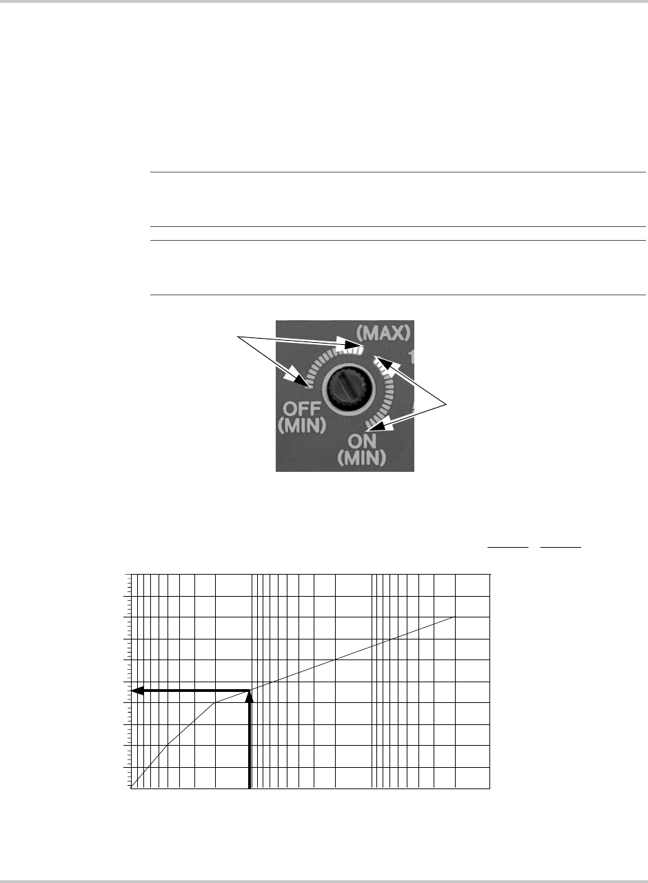
Front Panel Controls and Indicators
975-0012-01-02 Rev A 3–9
Over Discharge Protection (ODP)
When enabled, ODP shuts down the inverter at a specified voltage (low battery
cutoff) to protect the batteries from over discharge damage. The inverter circuitry
calculates the lowest (safe) DC voltage (leaving approximately 20% battery
capacity) based on the position the Battery Type Selector switch and the amount
of current drawn by the load. Under no-load conditions this level is typically
between 11.8 and 12.0 Vdc (for a 12-volt battery bank).
Important:
The range of set points between 2 and 5 o’clock also determine the low AC
Transfer Voltage. This must be considered when adjusting this potentiometer with ODP
enabled (see Table 3-3).
Important:
When ODP is disabled (set points between 9 and 1 o’clock), the inverter is
programmed to shut OFF when the batteries reach approximately 8.5 Vdc (1.4166 V/cell)
for 12-Vdc systems (17 Vdc for 24-volt systems).
Figure 3-5
ODP Enabled/Disabled Positions
Figure 3-6
Automatically Calculated Discharge Cutoff Voltage per Cell
ODP Disabled
Range
ODP Enabled
Range
10.1 0.01 0.001
Discharge Rate/Battery Capacity
1.55
1.5
1.65
1.6
1.75
1.7
1.85
1.8
1.95
1.9
2
Cell Voltage
12 Vdc
9.0
9.6
10.2
10.8
11.4
12.0
24 Vdc
18.0
19.2
20.4
21.6
22.8
24.0
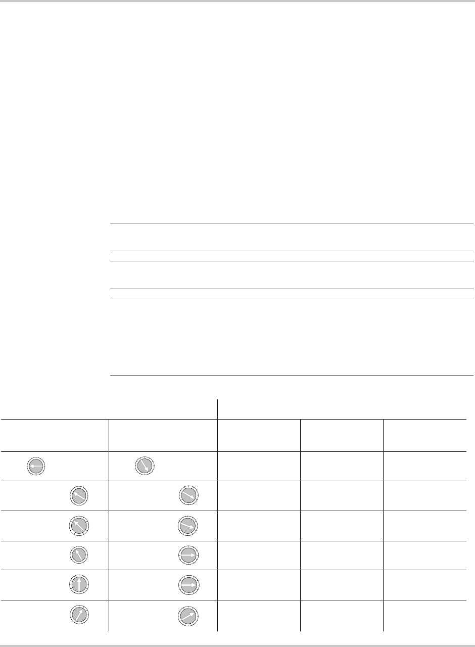
Operation
3–10 975-0012-01-02 Rev A
AC Transfer Voltage
During normal operation, the inverter supplies AC power to the applied loads
through the pass-through circuit and simultaneously charges the system batteries.
Whenever the external AC source drops below the AC Transfer Voltage (set by
the potentiometer), the inverter switches to battery power in order to maintain the
connected load.
Examples (120 Vac inverter system):
1. The AC Transfer Voltage potentiometer is set to 9:00 o’clock with ODP
disabled. Whenever the incoming AC voltage drops to 40 volts or below, the
inverter will switch to battery power.
2. The AC Transfer Voltage potentiometer is set to 2:00 o’clock with ODP
enabled. Whenever the incoming AC voltage drops to 105 volts or below, the
inverter will switch to battery power.
Important:
ODP does not affect the operation of the AC Transfer Voltage. ODP is
either ON or OFF, depending upon the position of the potentiometer.
Important:
There are 6 settings available for the AC Transfer Voltage for both ODP
OFF and ON as shown in the Table 3-3 below.
Important:
To achieve the fastest transfer time (typically less than 16 ms), set the AC
Transfer Voltage potentiometer near the 2:00 o’clock position (with the ODP enabled); or,
near the 1:00 o’clock position (with the ODP disabled). If a high number of “nuisance
transfers” caused by transients on the AC line occur, adjust the potentiometer from the
maximum position toward the minimum position (i.e., 2 o’clock toward 5 o’clock with
ODP enabled; or 1 o’clock toward 9 o’clock with ODP disabled).
Table 3-3
ODP/AC Transfer Voltage
ODP Adjustment AC Transfer Voltage
ODP Disabled ODP Enabled
100 to 105 Vac
(-J/-K Models) 120 Vac Models
220 to 230 Vac
(-W /-E Models)
9:00 5:00 30 Vac 45 Vac 90 Vac
Approximate Approximate 77 Vac 85 Vac 170 Vac
Approximate Approximate 81 Vac 90 Vac 180 Vac
Approximate Approximate 86 Vac 95 Vac 190 Vac
Approximate Approximate 90 Vac 100 Vac 200 Vac
Approximate Approximate 95 Vac 105 Vac 210 Vac
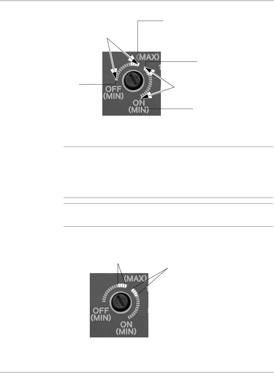
Front Panel Controls and Indicators
975-0012-01-02 Rev A 3–11
Figure 3-7
ODP Enabled/Disabled Positions
Important:
Most AC appliances will operate properly with an AC pass-through
voltage between 95 and 105 volts. Setting the AC Transfer Voltage potentiometer between
these values will allow the incoming source voltage to drop to this level and still operate
the connected appliances (load). If the appliances do not operate properly at the lower AC
utility pass-through voltage, increasing the setting of the potentiometer (toward MAX)
allows the inverter to transfer to battery power (providing full AC output) during these
periods.
Important:
When setting the AC Transfer Voltage potentiometer for generator
applications, the setting may need to be lowered if high powered loads cause the generator
voltage to momentarily drop.
AC Transfer Voltage (Adjustable)
with ODP Enabled
AC Transfer Voltage (Adjustable)
with ODP Disabled
Maximum
(105 Vac for 120 Vac models)
Maximum
(105 Vac for 120 Vac models)
Minimum
(45 Vac for 120 Vac models)
Minimum
(45 Vac for 120 Vac models)
Figure 3-8
Typical Setting for Most Utility Application
Typical Setting Range for Utility
Application (ODP OFF)
Typical Setting Range for Utility
Application (ODP ON)
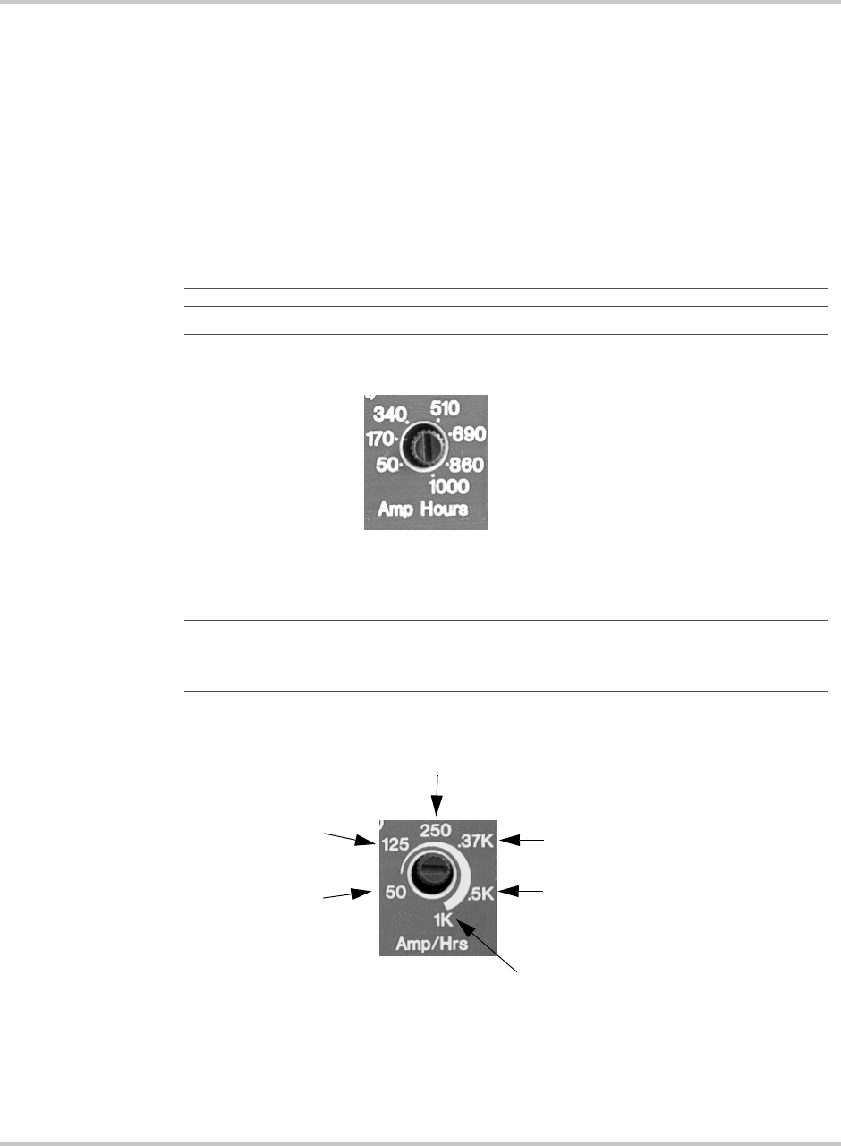
Operation
3–12 975-0012-01-02 Rev A
Battery Capacity
The Battery Capacity potentiometer is used to set the correct charge profile for the
battery capacity (amp-hours) used with the inverter (see illustration below). The
setting allows the inverter to calculate over-discharge protection values and also
the end of the Bulk/Absorption charge mode, at which point the inverter switches
to the Float mode of battery charging.
The potentiometer should be adjusted as close as possible to the actual capacity of
the battery bank for optimum charging. If the system’s battery bank is larger than
1000 amp-hours, set the potentiometer for 1K.
Important:
If using dual inverters configurations, set each charger for half the value.
Important:
Most battery manufacturers list the amp/hour rating on the battery label.
Figure 3-9
Battery Capacity Potentiometer (new)
Important:
The Battery Capacity (Amp/Hrs) potentiometer values have changed
between the minimum value of 50 Ah and 1 kAh. Please use the photo that matches your
unit.
Figure 3-10
Battery Capacity Potentiometer (old)
50 amp-hours
(small battery bank)
1000 amp-hours
(1000 amp-hour or larger
battery banks)
50 amp-hours
(small battery bank)
1000 amp-hours
(1000 amp-hour or larger battery banks)
125 amp-hours
250 amp-hours
370 amp-hours
500 amp-hours
Front Panel Controls and Indicators
975-0012-01-02 Rev A 3–13
LED Indicators
There are four LEDs on the inverter’s front panel, indicating inverter status,
battery condition, over temperature/overload conditions and charger status. These
LEDs blink or change color depending on the condition or function they are
displaying.
Inverter Mode LED - Green
The green Inverter Mode LED lights (solid) to indicate the inverter is running on
batteries (full wave operation). When the inverter is in search mode (no load
applied) the LED flashes 2 to 3 times per second. During AC line operation, with
AC passing directly through to the connected load, the LED remains OFF.
Over Temp / Overload LED - Red / Green (error condition)
The Over Temp / Overload LED is a dual color, dual function indicator. When the
inverter’s temperature is too high for safe operation, the LED lights (red) to
indicate the Over Temp condition. When the temperature returns to a safe level,
the LED turns OFF. If the condition persists, the inverter will shut down, cool and
then restart.
Whenever the current draw exceeds a value programmed into the micro-
controller, the LED lights (green) to indicate the Overload condition. The LED
can remain ON for up to one hour (before inverter shutdown) if the condition is
caused by a fault in the charger circuit. When the fault condition clears, the LED
turns OFF. If the condition is caused by backfeed (connecting the AC line to the
inverter’s output) the LED will remain ON for approximately 10 seconds before
the inverter shuts down.
Battery High/Battery Low LED - Red/Green (error condition)
The Battery Hi / Battery Low LED is a dual-color, dual-function indicator.
Whenever battery voltage exceeds a safe value, the LED lights red to indicate the
condition. This value is typically 15.5 volts DC for a 12 volt system (31 volts DC
for a 24 volt system). If the condition persists, the inverter will shut down until the
battery voltage returns to a safe level and then restart.
Figure 3-11
LED Indicators
INVERTER
MODE
OVER TEMP/OVERLOAD
BATTERY HIGH/LOW
BATTERY CHARGER

Operation
3–14 975-0012-01-02 Rev A
Whenever the battery voltage drops to its lowest (safe) level (as calculated by the
ODP), the LED lights green to indicate the condition. If the condition persists, the
inverter will shut down until the battery voltage returns to a safe level and then
restart.
Charger LED - Orange / Green
The Charger LED is a dual color (red/green), triple function indicator.
• When the charger is in Bulk mode, the LED lights orange.
• When the charger is in Absorption mode, the LED blinks orange.
• When the charger is in Float mode, the LED lights green.
Audible Indicator (internal)
A buzzer is located on the control board as an audible alert to fault conditions such
as Battery High/Battery Low, or Overload. Steady buzzing indicates an impending
inverter shut down. A pulsing chirp indicates the inverter is temporarily off-line
due to a fault condition (either within the inverter or related to the system).
Important:
In renewable energy applications (solar, wind, hydro, etc.) the DC charge
controllers must be set to a level below the inverter’s maximum input voltage or the
inverter shuts OFF.
Important:
The inverter automatically restarts when the following error conditions are
detected: LOW/HIGH BATTERY, OVER TEMPERATURE, or a quick duration
SHORTED OUTPUT or OVER-CURRENT. The inverter shuts OFF and requires a
MANUAL restart if the following conditions are detected: a prolonged overload condition
(approximately 10 seconds) or the inverter’s output is connected directly to an AC power
source (utility grid or generator).
Important:
Orange is a flickering mix of red and green. It can look different depending
on the angle at which the LED is viewed. It should never be a solid red.
Important:
The battery charger control circuit operates from the battery voltage. If the
battery voltage falls below 7 volts, the inverter/charger will not operate. The batteries
must first be recharged using a stand-alone charger to bring the voltage up to a level where
the inverter/charger can operate.
Front Panel Controls and Indicators
975-0012-01-02 Rev A 3–15
Circuit Breakers
The DR Inverter contains two circuit breakers located on the right-hand side of the
chassis, directly above the AC input terminal block. The pass-through AC input
circuit breaker protects the AC wiring and connected load. The charger AC input
circuit breaker protects the charger circuit. The breakers are rated for the
maximum charge rate and pass-through current allowed according to the rating of
the internal relay.
Table 3-4
AC Pass-through Circuit Breakers
Models DR15XX DR24XX DR36XX
120 Vac 30 amps 30 amps 30 amps
210-230 Vac 15 amps 15 amps N/A
Table 3-5
Battery Charger Circuit Breakers
Models DR15XX DR24XX DR36XX
120 Vac 20 amps 30 amps 30 amps
210-230 Vac 8 amps 15 amps N/A
Figure 3-12
AC Pass-through and Charger AC Input Circuit Breakers
AC Pass-through
Circuit Breaker
Charger AC Input
Circuit Breaker
Operation
3–16 975-0012-01-02 Rev A
Start-up
Once the inverter is properly connected to the batteries, AC source, and loads
(using a sub-panel) the inverter is ready for operation. Recheck the controls and
ensure they are in the proper position. Recheck all wiring and ensure it is correct.
Starting the inverter:
1. Apply DC power to the inverter by switching on the DC disconnect circuit
breaker. The inverter will go through a self-test and then shut OFF.
2. Press the ON/OFF button once. The inverter will sound an audible chirp.
3. Apply AC power to the inverter.
4. The inverter starts charging the batteries in the Bulk mode, indicated by the
CHARGER LED illuminating a solid orange.
5. Using a true RMS AC voltmeter, check the output voltage of the inverter. This
voltage can be checked at either the AC terminal block or in the sub-panel
(between the HOT and NEUTRAL lines). The voltage should be 120 Vac
(230 Vac for “E” models, 220 Vac for “W” models, or 105 Vac for “J” and
“K” models). (Non-true RMS meters register from 90 to 110 Vac.)
6. Switch the AC disconnect circuit breaker to OFF. The inverter will go into the
inverter mode (if a sufficient load is applied to the AC output while in the
search mode). The green INVERTER MODE LED will light solid indicating
the inverter is active. The voltage on the AC output of the inverter will remain
the same as above (± 5% maximum).
7. Reapply the AC power by switching the AC disconnect to ON. Allow the
batteries to fully recharge.
Important:
If the inverter is in the SEARCH MODE (INVERTER MODE LED
flashing) and a sufficient load is not available to bring the inverter up to full voltage, turn
the SEARCH MODE WATTS potentiometer fully CCW to defeat the search function.
Figure 3-13
Startup Items
Important:
The unit will not use renewable energy for AC output as long as AC input
(utility or generator) is available to the inverter.
Charger LED
INVERTER MODE LED
POWER ON/OFF Switch
SEARCH MODE WATTS Potentiometer

Charger Mode
975-0012-01-02 Rev A 3–17
Charger Mode
3-Stage Charging Process
The charging cycle uses a 3-stage charging process to maintain the batteries.
Whenever nominal AC is present at the inverter’s input, it passes power through
to the connected load and begins charging the batteries, indicated by the dual color
BATTERY CHARGER LED.
Bulk Charge
Bulk charge is the first stage in the charging process and provides the batteries
with a controlled, constant current. A solid orange BATTERY CHARGER LED
indicates bulk charge. The bulk charge level is adjustable using the BATTERY
CHARGER RATE potentiometer. Once the battery voltage rises to the bulk
voltage threshold, the charger then switches to the absorption mode.
Absorption Charge
Absorption charge is the second stage of battery charging and provides the
batteries a controlled, constant voltage for a set period of time. A blinking orange
BATTERY CHARGER LED indicates absorption charge.
During this stage the current supplied to the batteries slowly decreases. When the
current equals the programmed return amps value (battery bank capacity/40) set
with the BATTERY BANK CAPACITY potentiometer, the charger switches to
the third stage–float.
Float Charge
Float charge, the final stage of battery charging, maintains a charge to the batteries
whenever AC is present on the inverter’s input. A solid green BATTERY
CHARGER LED indicates float charging which reduces battery gassing,
minimizes watering requirements (for flooded batteries) and ensures the batteries
are in a constant state of readiness.
A new 3-stage charging cycle is initiated after an AC source is reapplied to the
inverter’s AC input terminals such as after a utility outage.
Important:
If there are DC loads connected to the battery, the current may never
decrease to the level to initiate the float stage. The inverter/charger incorporates a timer
circuit which starts counting when AC voltage is applied. To ensure that the charger does
not stay indefinitely in the absorption charge mode, the timer automatically switches to
the float charge mode when 12 hours have elapsed.
Important:
The Float Charge is a very low-current charge, also called a “trickle-
charge”. Some batteries may require higher current. Consult the battery manufacturer to
determine if the batteries being used can handle a float charge. The inverter will adjust its
charge rate to meet the battery requirement.
Operation
3–18 975-0012-01-02 Rev A
Equalize Charging
Equalize charging is a special mode of battery charging. During use, the battery’s
cells can become unequal in the voltage and current they can deliver. This is due
to a buildup of sulfate on the plates as well as stratified electrolyte. Sulfate
prevents the cells from receiving or delivering full power. If the sulfate is left on
the plates, it will harden, and permanently reduce the battery’s capacity.
Stratification separates the heaver acid from the water, and the concentrated acid
remains at the lower portion of the plates, eventually corroding them.
Equalize charging holds the battery at the Equalize voltage for a minimum of
6 hours. This stirs up the electrolyte, distributing the acid, and removing the
sulfate from the plates. Equalizing the batteries every month or two (depending on
usage) prolongs the life of the batteries and provides better battery performance.
To Set the Equalize Charge:
1. Remove all DC loads connected to the batteries.
2. Remove all battery vent caps.
3. Check the battery water level, it should be just over the top of the plates (do
not overfill). Use only distilled water for filling batteries.
Figure 3-14
Charger Controls and Indicators
Battery Charger LED
Solid Orange = Bulk
Blinking Orange = Absorption
Solid Green = Float
Battery Capacity
CAUTION: Explosion Hazard
Only unsealed or vented batteries should be equalize charged. Since Hydrogen and
oxygen gases are produced when equalized, provide adequate ventilation and remove all
sources of ignition to prevent explosion. Remove DC loads while equalizing as they can
be damaged by the higher battery voltage. Consult the battery manufacturer’s
recommendation for equalize charging settings.

Charger Mode
975-0012-01-02 Rev A 3–19
4. Set the BATTERY TYPE SELECTOR switch to position “0” or “1”. To start
the equalization charging process, cycle the AC power (i.e., disconnect and
then reconnect the AC source). A solid orange BATTERY CHARGER LED
indicates equalize charge.
a) Position “0” equalizes the batteries at the rate of the battery bank capacity
divided by 40 (C/40) at a voltage of 15 volts for 12-volt systems or
30 volts for 24-volt systems. This is set with the BATTERY CAPACITY
potentiometer.
b) Position “1” equalizes the batteries at the rate set with the BATTERY
CHARGER RATE CONTROL at a voltage of 15.5 volts for 12-volt
systems or 31 volts for 24-volt systems.
When the voltage condition is met and 6 hours have elapsed, the charger will
switch to the float mode. If the condition is not met (i.e., the current draw is
above the rate set with the BATTERY CAPACITY potentiometer (position
“0”) or BATTERY CHARGER RATE potentiometer (position “1”)), the
charger will continue until the condition is met, or for a maximum of
12 hours. At this point the charger switches to float at the equalize 1 or 2
voltage setting (see Figure 3-1, “Battery Type Selector Switch Settings” on
page 3–5).
5. Reset the BATTERY TYPE SELECTOR potentiometer to the appropriate
setting for the system’s batteries when the Equalize charge has completed.
Important:
Recheck the water the level after equalize charging and refill if necessary.
Important:
Refer to “Battery Maintenance” on page B–13 for additional information.
Figure 3-15
Equalize Positions on Battery Type Selector Switch
Equalize 1
Equalize 2
Operation
3–20 975-0012-01-02 Rev A
Figure 3-16
Equalize 1 Battery Charger Rate Potentiometer (Position “1”)
See Table 3-1 Switch Position “1”.
Figure 3-17
Equalize 2 Battery Capacity Rate Potentiometer (Position “0”)
See Table 3-1 Switch Position “0”.
4Troubleshooting
Chapter 4, “Troubleshooting” contains information about how to
troubleshoot possible error conditions while using the DR
Inverter/Charger.

Troubleshooting
4–2 975-0012-01-02 Rev A
Troubleshooting the DR Inverter
Table 4-1 provides a list of possible error conditions that may occur, their possible
causes, and possible solutions to resolve the error condition.
Table 4-1
Troubleshooting the DR Inverter
Error Condition Possible Cause Solution
No AC output voltage and no
warning LEDs on ON.
Battery voltage at the inverter
terminals is too high or low.
Check the battery voltage, fuses or
breakers, and cable connections.
AC output voltage is low and the
inverter turns loads ON and OFF.
Low Battery. Check the condition of the batteries
and recharge if possible.
Replace the batteries.
AC output is low. Loose or corroded battery
connections.
Loose AC output connections.
Wrong voltmeter is being used.
Check and clean all DC connections.
Check all AC output connections.
Use a True RMS voltmeter.
Charger is inoperative. AC voltage has dropped
out-of-tolerance
Loose AC input connections.
Check the AC voltage for proper
voltage and frequency (depending on
model).
Check all AC output wiring
connections
Charger is supplying a lower charge
rate.
Charger controls are improperly set.
Low peak AC input voltage (169 Vacp
required for full charger output)
Loose or corroded battery
connections.
Loose AC input connections.
Generator is unstable - charger is
losing synchronization.
Refer to the section on adjusting the
“Charger Rate”.
Use larger generator (increasing AC
voltage/RPM’s may help).
Check and clean all DC connections.
Check all AC output wiring
connections.
Turn BATTERY CHARGER RATE
potentiometer down to less than
halfway until problem is gone.
AC LEDs flicker while charging. Generator is unstable and charger is
losing synchronization.
Turn BATTERY CHARGER RATE
potentiometer down to less than
halfway until problem is gone.

Problem Loads
975-0012-01-02 Rev A 4–3
Problem Loads
The inverter can drive most loads, however, there are special conditions that can
cause a load to behave differently than expected. The following describes some of
the common problems encountered when using an inverter.
Ceiling Fans
Most large diameter, slow turning fans run correctly, but generate more noise than
when connected to utility power. High speed fans tend to operate normally.
Cell Phones
Some cellular telephones experience interference in the form of a clicking sound.
Computers and Sensitive Electronics
Some computers and sophisticated electronics have power supplies that do not
present a load until correct line voltage is available. When this occurs, each unit
waits for the other to begin. This can usually be solved by plugging in an
additional load (such as a lamp) to bring the inverter out of its search mode. Also,
when using a computer, avoid starting large loads.
Consumer Electronics
AM radios tend to pick up inverter noise, especially on the lower half of their
band. Inexpensive tape recorders are likely to experience noise as well. When
using sensitive electronic devices, avoid starting large loads.
CHARGER LED:
- indicates charging, but no charge
is going to the batteries.
- is ON, but there is no output
power.
Circuit Breaker on the side of the
inverter is open.
No AC voltage on inverter’s AC
terminal block.
Good AC voltage on inverter’s AC
terminal block.
Reset the AC CHARGER circuit
breaker on the side of the unit.
Check “AC PASS-THRU” Circuit
Breaker on the side of the inverter.
Check for open AC output breakers
or uses and AC wiring connections.
Charger turns OFF while charging
from a generator
High peak AC input voltages from the
generator
Load the generator down with a
heavy load.
Turn the generator output voltage
down.
Table 4-1
Troubleshooting the DR Inverter
Error Condition Possible Cause Solution

Troubleshooting
4–4 975-0012-01-02 Rev A
Clocks
The inverter’s crystal controlled oscillator keeps the frequency accurate to within
a few seconds a day; however, external loads in the system may alter the inverter’s
output waveform causing clocks to run at different speeds. There may be periods
where clocks keep time and then mysteriously do not. This is because most clocks
do not draw enough power to trigger the load sensing circuit. In order to operate,
especially with no other loads present, the inverter’s load sensing circuit will have
to be defeated. Refer to the Operation/Search Mode Watts.
Decreasing Loads
If the amount of power a load draws decreases after it has been switched on (such
as with a small motor) and its current draw becomes less than the load sensing
threshold, it will be turned alternately ON and OFF by the inverter. This can
usually be solved by plugging in an additional load (such as a lamp).
Dimmer Switches
Most dimmer switches lose their ability to dim the lights when used with an
inverter and operate only in the fully ON or OFF position. Newer, microprocessor
controlled dimmers tend to work better in inverter applications.
Fluorescent Lights
Some devices cannot be detected by the inverter’s load sensor and will not
operate. Small fluorescent lights are the most common example. This can usually
be solved by plugging in an additional load. Also, try turning the lamps AC plug
over.
Heavy Loads
If the battery bank cannot deliver the necessary amperage to drive a heavy load,
the inverter will shut OFF. The battery voltage will then slowly rise back above
the low voltage threshold causing the inverter to resume operation. As soon as the
heavy load draws the batteries down, the cycle will continue unless the load is
reduced or an additional source of power is added.
Microwave Ovens
Microwave ovens are sensitive to peak output voltages. The higher the voltage,
the faster they cook. Since the inverter’s peak output voltage is dependent upon
battery voltage and load size, the microwave’s cook time may need to be
increased.
Problem Loads
975-0012-01-02 Rev A 4–5
Printers
Most inkjet type printers work well in inverter applications. Laser printers,
however, require high current for their fusing circuit and are not recommended for
use with an inverter.
Rechargeable Devices
When first using a rechargeable device, monitor its temperature for 10 minutes to
ensure it does not become abnormally hot. Excessive heat will indicate that it is
incompatible with the inverter.
Undersized Loads
If the power consumed by a device is less than the inverter’s search mode circuitry
threshold, it will not run. This can usually be solved by plugging in an additional
load such as a 100 watt light bulb.
CAUTION: Equipment Damage
Some products can be damaged when used with modified sine-wave power. If in doubt,
check with the product’s manufacturer.
4–6
ASpecifications
Appendix A, “Specifications” contains information about the
electrical specifications and environmental specifications of the DR
Inverter/Charger.

Specifications
A–2 975-0012-01-02 Rev A
Specifications of the DR Inverter
Table A-1 provides the electrical specifications for the DR Inverter/Charger
(120 Vac/60 Hz. models).
Table A-2 provides the electrical specifications for the DR Inverter/Charger
(220 Vac/60 Hz. models).
Table A-3 provides the electrical specifications for the DR Inverter/Charger
(230 Vac/50 Hz. models).
Table A-4 provides the environmental specifications for all models of the DR
Inverter/Charger.
Table A-1
Electrical Specifications for the DR Inverter/Charger
a
- 120 Vac/60 Hz Models
Model DR1512 DR2412 DR1524 DR2424 DR3624
AC Input Voltage 120 Vac 120 Vac 120 Vac 120 Vac 120 Vac
AC Input Low
Transfer Voltage
40-105 Vac 40-105 Vac 40-105 Vac 40-105 Vac 40-105 Vac
AC Input Currentb45 amps 55 amps 45 amps 55 amps 55 amps
Continuous Power
(@ 25°C)
1500 VA 2400 VA 1500 VA 2400 VA 3600 VA
Continuous Output
(@25 °C)
12.5 amps AC 20 amps AC 12.5 amps AC 20 amps AC 30 amps AC
Efficiency 94% max 94% max 94% max 95% max 95% max
AC Output Voltage
(rms)
120 Vac 120 Vac 120 Vac 120 Vac 120 Vac
Frequency:
(± 0.04% Crystal
controlled)
60 Hz 60 Hz 60 Hz 60 Hz 60 Hz
Surge Capability:
5 sec Rating 2400 watts 4200 watts 3500 watts 6200 watts 7500 watts
1 mSec Rating 38 amps AC 77 amps AC 412 amps AC 80 amps AC 100 amps AC
100 mSec Rating 27 amps AC 55 amps AC 29 amps AC 58 amps AC 72 Amps AC
DC Input Current:
Search Mode 0.045 amps 0.055 amps 0.030 amps 0.030 amps 0.030 amps
Full Voltage 0.700 amps 0.900 amps 0.350 amps 0.450 amps 0.500 amps
DC Current at
Rated Power
165 amps 280 amps 80 amps 140 amps 210 amps
Short Circuit
Current
400 amps 800 amps 280 amps 560 amps 720 amps

Specifications of the DR Inverter
975-0012-01-02 Rev A A–3
DC Input Voltage
(nominal)c
12.6 Vdc 12.6 Vdc 25.2 Vdc 25.2 Vdc 25.2 Vdc
DC Input Voltage
Range
10.8 to 15.5 Vdc 10.8 to 15.5 Vdc 21.6 to 31.0 Vdc 21.6 to 31.0 Vdc 21.6 to 31.0 Vdc
Auto Low Battery
Protection enabled
11 V 11 V 22 V 22 V 22 V
DC Charger Rate
(Adjustable)
0 to 70 amps 0 to 120 amps 0 to 35 amps 0 to 70 amps 0 to 70 amps
Common Specifications:
Voltage Regulation
(maximum)
± 5%
Voltage Regulation
(Typical)
±2. 5%
Waveform modified sine wave
Load Power Factor
(allowed)
0.5 to 1.0 (leading or lagging)
Adjustable Load
Sensing Range
5 watts minimum to 100 watts maximum
Series Operation Yes
Force Air Cooling Variable speed fan
Automatic Transfer
Relay
30 amps
Number of
Charging Profiles
10
Three-stage
Charging
Yes (float, absorption, bulk)
Temperature Comp
Probe (BTS)
optional
Remote Control
(RC8)d
optional
a.Specifications subject to change without notice.
b.This is the minimum AC current required to obtain full pass-through and maximum battery charging.
c.Product may not meet voltage regulation specifications at other than "Input Nominal" at full-rated load.
d.Also compatible with the RC4.
Table A-1
Electrical Specifications for the DR Inverter/Charger
a
- 120 Vac/60 Hz Models
Model DR1512 DR2412 DR1524 DR2424 DR3624

Specifications
A–4 975-0012-01-02 Rev A
Table A-2
Electrical Specifications for the DR Inverter/Chargers
a
- 220 Vac/60 Hz Models
Model DR1512W DR2412W
AC Input Voltage 220 Vac 220 Vac
AC Input Low Transfer Voltage 80 to 210 Vac 80 to 210 Vac
AC Input Currentb45 amps 55 amps
Continuous Power (@ 25°C) 1500 VA 2400 VA
Continuous Output (@25 °C) 6.8 amps AC 6.8 amps AC
Efficiency 94% max 94% max
AC Output Voltage (rms) 220 Vac 220 Vac
Frequency: (± 0.04% Crystal controlled) 60 Hz. 60 Hz.
Surge Capability:
1 mSec Rating 20 amps AC 20 amps AC
DC Input Current:
Search Mode 0.045 amps 0.055 amps
Full Voltage 0.700 amps 0.900 amps
DC Current at Rated Power 150 amps 80 amps
Short Circuit Current 400 amps 800 amps
DC Input Voltage (nominal)c12.6 Vdc 12.6 Vdc
DC Input Voltage Range 10.8 to 15.5 Vdc 10.8 to 15.5 Vdc
Auto Low Battery Protection enabled 11 V 11 V
Charger Rate (Adjustable) 0 to 70 amps 0 to 120 amps
Common Specifications:
Voltage Regulation (maximum) ± 5%
Voltage Regulation (Typical) ±2. 5%
Waveform modified sine wave
Load Power Factor (allowed) 0.5 to 1.0 (leading or lagging)
Adjustable Load Sensing Range 5 watts minimum to 100 watts maximum
Series Operation NO
Force Air Cooling Variable speed fan
Automatic Transfer Relay 20 amps
Number of Charging Profiles 10
Three-stage Charging Yes (float, absorption, bulk)

Specifications of the DR Inverter
975-0012-01-02 Rev A A–5
Temperature Comp Probe (BTS) optional
Remote Control (RC8)doptional
a.Specifications subject to change without notice.
b.This is the minimum AC current required to obtain full pass-through and maximum battery charging.
c.Product may not meet voltage regulation specifications at other than "Input Nominal" at full-rated load.
d.Also compatible with the RC4.
Table A-2
Electrical Specifications for the DR Inverter/Chargers
a
- 220 Vac/60 Hz Models
Model DR1512W DR2412W
Table A-3
Electrical Specifications for the DR Inverter/Charger
a
- 230 Vac/50 Hz Models
Model DR1512E DR1524E DR1548E DR2424E
AC Input Voltage 230 Vac 230 Vac 230 Vac 230 Vac
AC Input Low Transfer
Voltage
80 to 210 Vac 80 to 210 Vac 80 to 210 Vac 80 to 210 Vac
AC Input Currentb55 amps 55 amps 55 amps 55 amps
Continuous Power
(@ 25°C)
1500 VA 1500 VA 1500 VA 2400 VA
Continuous Output
(@25 °C)
12.5 amps AC 20 amps AC 12.5 amps AC 20 amps AC
Efficiency 94% max 94% max 94% max 95% max
AC Output Voltage
(rms)
230 Vac 230 Vac 230 Vac 230 Vac
Surge Capability:
1 mSec Rating 20 amps AC 20 amps AC 20 amps AC 40 amps AC
DC Input Current:
Search Mode 0.045 amps 0.055 amps 0.030 amps 0.030 amps
Full Voltage 0.700 amps 0.900 amps 0.350 amps 0.450 amps
DC Current at Rated
Power
165 amps 280 amps 80 amps 140 amps
Short Circuit Current 400 amps 800 amps 280 amps 560 amps
DC Input Voltage
(nominal)c
12.6 Vdc 25.2 Vdc 50.4 Vdc 25.2 Vdc
DC Input Voltage
Range
10.9 to 15.5 Vdc 21.8 to 31 Vdc 43.6 to 62 Vdc 21.8 to 31 Vdc

Specifications
A–6 975-0012-01-02 Rev A
Auto Low Battery
Protection enabled
11 V 11 V 22 V 22 V
DC Charger Rate
(Adjustable)
0 to 70 amps 0 to 35 amps 0 to 17.5 amps 0 to 70 amps
Common Specifications:
Voltage Regulation
(maximum)
± 5%
Voltage Regulation
(Typical)
±2. 5%
Waveform modified sine wave
Load Power Factor
(allowed)
0.5 to 1.0 (leading or lagging)
Adjustable Load
Sensing Range
5 watts minimum to 100 watts maximum
Series Operation NO
Force Air Cooling Variable speed fan
Automatic Transfer
Relay
20 amps
Number of Charging
Profiles
10
Three-stage Charging Yes (float, absorption, bulk)
Temperature Comp
Probe (BTS)
optional
Remote Control (RC8)doptional
a.Specifications subject to change without notice.
b.This is the minimum AC current required to obtain full pass-through and maximum battery charging.
c.Product may not meet voltage regulation specifications at other than "Input Nominal" at full-rated load.
d.Also compatible with the RC4.
Table A-3
Electrical Specifications for the DR Inverter/Charger
a
- 230 Vac/50 Hz Models
Model DR1512E DR1524E DR1548E DR2424E

Specifications of the DR Inverter
975-0012-01-02 Rev A A–7
Table A-4
Environmental Specifications for the DR Inverter/Charger
a
a.Specifications subject to change without notice.
Model DR1512 DR2412 DR1524 DR2424 DR3624
Dimensionsb
b.Allows for hardware extensions such as mounting rails, DC terminals, and front panel controls.
8.5" w x 7.25" H x 21" D (21.6 cm W x 18.4 cm H x 54.6 cm D
Unit Weight 35 lbs (16 kg) 45 lbs (21 kg) 35 lbs (16 kg) 40 lbs (16 kg) 45 lbs (21 kg)
“E” Models 38 lbs (18 kg) N/A 39 lbs (18 kg) (45 lbs (21 kg) N/A
Ambient Temp Range (rated 0 to 25 °C):
Operating 0 °C to +50 °C
Storage -55 °C to +75 °C
Altitude:
Operating 15,000 feet
Non-operating 50,000 feet
Mounting Wall-mount (with 16" mounting centers)
Shelf Mount
A–8
BBattery Information
Appendix B, “Battery Information” supplies general information
about batteries such as battery types, battery bank sizing, battery
configurations, and battery care. For detailed information, see your
battery manufacturer or your system designer.

Battery Information
B–2 975-0012-01-02 Rev A
Introduction
Batteries Batteries are available in different sizes, amp-hour ratings, voltage, liquid or gel,
vented or non-vented, chemistries, etc. They are also available for starting
applications (such as an automobile starting battery) and deep discharge
applications.
Recommendations Consider the following recommendations for battery use.
• Use only the deep discharge types for inverter applications.
• Use the same battery type for all batteries in the bank.
• Use only batteries from the same lot and date in your battery bank. This
information is usually printed on a label located on the battery.
Battery Types
There are two principal types of batteries: starting and deep-discharge (with
several different types of chemistries). Batteries can be either sealed or non-sealed
(vented).
Deep discharge The battery types recommended for use in an inverter system are: Flooded Lead
Acid (FLA), Sealed Gel Cells (GEL), Sealed Absorbed Glass Mat (AGM); and
alkaline types Nickel-iron (NiFe) and Nickel-Cadmium (NiCad).
Starting Automotive (starting) batteries are designed to provide high starting current for
short periods of time and are not appropriate for inverter applications.
Deep-cycle Flooded Lead Acid (FLA)
Description A flooded lead acid battery is designed to be deep-discharged before being
recharged, making it suitable for inverter applications. Flooded batteries require
periodic maintenance consisting mainly of adding distilled water to the cells.
Attributes
Types of FLA Batteries Attributes
Golf Cart • Popular for smaller off-grid home
systems
• Many medium sized inverter
systems use “L16” batteries
• Rugged, long lasting
• Typically rated at 6 volts
(220 to 350 amp hours)
Industrial (electric forklift) • Popular in large inverter systems
• Extremely rugged - lasts up to 10
years or more in an inverter system
• Typically 2 volt cells
(1,000 amp hours or more)

Battery Types
975-0012-01-02 Rev A B–3
Sealed Batteries (Gel and AGM)
Description Gel Cell and absorbed glass mat (AGM) batteries are sealed and do not require the
addition of distilled water. Since these batteries are valve regulated, over-charging
can cause irreversible damage.
Attributes Attributes of sealed batteries are:
NiCad and NiFe Batteries
Disadvantages These types of batteries can be used but are not optimized for the DR Inverter for
the following reasons:
• Alkaline batteries, such as NiCad and NiFe types, have a nominal cell voltage
of 1.2 volts per cell.
Xantrex inverters and battery chargers are optimized for use with lead acid
batteries having a nominal 2.0 volts per cell (that is, 12 cells for a 24-volt
system and 24 cells for a 48-volt system).
The number of cells required in a battery bank for alkaline batteries must,
therefore, be adjusted for a 24- and 48-volt system
(i.e, 20 cells for a 24-volt system and 40 cells for a 48-volt system).
• Alkaline batteries require a higher charge voltage to fully recharge, and drop
to a lower voltage during discharge compared to a similarly sized lead-acid
type battery.
Other options Another option for 24 volt (only) alkaline battery banks is to use only 19 cells
instead of 20. Fewer cells allow the battery charger to operate more closely to the
settings used for lead-acid batteries. However, the battery voltage will drop to as
low as 18 volts when discharging the batteries.
Consult the battery manufacturer or supplier regarding system requirements and
battery charger settings for alkaline type batteries.
Types of Sealed Batteries Attributes
Gel Cell • Gelled electrolyte instead of
liquid
• Long life (up to 1500 cycles,
typical)
• Low self-discharge
Absorbed Glass Mat • Electrolyte is contained in
glass-fibre mats between battery
plates
• Similar to gel cells in
characteristics
• Good low temperature
performance

Battery Information
B–4 975-0012-01-02 Rev A
Understanding Battery Capacity Ratings
Discharge rate Deep cycle batteries have their amp-hour rating expressed as “at the x-hour rate”.
The hour rating refers to the time it takes to discharge the batteries. A faster hour
rate (6 hour rate) means more current is withdrawn from the batteries during their
discharge period. There is an inevitable amount of heat associated with the flow of
current through a battery and the higher amount of current the greater the amount
of heat will be generated. The heat is energy which is no longer available to the
battery to power loads. a relatively long discharge rate (72 hour rate) will result in
a larger number of amp-hours being available for electrical loads.
Calculation This calculation shows how to determine the level of current drawn from a battery
at any given hour rate—battery capacity divided by the hour rate equals the
current drawn from the battery. For example, a battery rated 220 Ah at a 6 hour
rate would be discharged at 36 amps (220/6).
For most residential applications of the DR Inverter the 72 hour rate is appropriate
because on average a household uses low amounts of current (lights, TV, radio for
example) with occasional bursts or higher consumption appliances like toasters or
washing machines. For those installations where high continuous electrical
consumption rates are anticipated it is more appropriate to use the 20 hour rate.
CCA rating The CCA rating (cold cranking amps) shown on starting batteries expresses
battery capacity in terms of its ability to provide large amounts of current for
intervals measured in minutes, not hours. This is why starting batteries are not
appropriate for inverter systems.
Battery Bank Sizing
Running time and
size
The battery bank’s size determines the length of time the inverter can supply AC
output power. The larger the bank, the longer the inverter can run.
Depth of discharge In general, the battery bank should be designed so the batteries do not discharge
more than 60% of their capacity on a regular basis. Discharging up to 80% is
acceptable on a limited basis, such as a prolonged utility outage. Totally
discharging a battery can reduce its effective life or permanently damage it.
Days of autonomy For off-grid, stand-alone applications, design a battery bank that can power the
loads for three to five days without requiring recharging. This design calculation
assumes a worst case scenario where there is no recharging taking place during
these days of autonomy.
Days of autonomy may vary depending upon the availability of other charging
sources, the critical nature of the load and other factors. If the system is to be
powered by renewable energy sources such as solar, wind, and micro-hydro,
determine the appropriate number of days of autonomy by allowing for cloudy or
calm weather as well as other seasonal variations in available energy.
If an engine generator is part of the system design, the days of autonomy can be
determined by simply deciding how often you are prepared to run the generator.
Significant battery cost reductions can be achieved by shortening the days of
autonomy and allowing a generator to run for a schedule time period daily.

Battery Bank Sizing
975-0012-01-02 Rev A B–5
Back up power systems which use utility power for recharging should use the
estimated number of days of maximum power outage for determining days of
autonomy.
Understanding Amp-hour Requirements
Amp-hours To estimate the battery bank requirements, you must first calculate the amount of
power you will draw from the batteries during your period of autonomy. This
power draw is then translated into amp hours (Ah)—the unit of measure to
express deep-cycle battery capacity.
Amp hours are calculated multiplying the current drawn by the load by the length
of time it will operate.
Watts to amps To calculate amps when the power consumption is expressed in watts, use the
following equation:
A = W/V
where W = watts and V = volts DC
For example:
A 100 watt light bulb will draw approximately 8.33 amps
8.33 = 100 /12
If the light runs for three hours it will consume (8.33 x 3) or 25 Ah of power.
Time and power The length of time a load is operated will affect the power draw. In some cases, an
appliance which draws a large wattage may not consume as many amp hours as a
load drawing fewer watts but running for a longer period of time.
For Example:
A circular saw draws 1500 watts or 125 amps. It takes 5 seconds to complete
a cross cut. Twelve such cuts would take a minute and you would consume 125
A x 0.016* hour = 2 Ah
*1/60 = 0.016
Observation The circular saw, while it draws more power, consumed fewer
amp hours of electricity because it ran for a short period of time.
Calculating Amp Hours
Calculations To determine the amp hours you will consume, you need to list your anticipated
loads and the length of time you will operate each one. Determine the number of
hours per day and the number of days during the week you will use the appliance.
For example, you use the microwave every day, but a breadmaker only once a
week. If you use an appliance for less than an hour, express the time as a decimal
portion of an hour.
Amps to watts All electrical appliances have labels which state their energy consumption. Look
for an amps rating on motors and a watts rating on other appliances.
If the label plate has expressed power consumption in amps, multiply by volts for
the watts required. (watts = volts x amps).

Battery Information
B–6 975-0012-01-02 Rev A
Considerations When calculating battery bank size, consider the following:
• Motors typically require 3 to 6 times their running current when starting.
Check the manufacturer’s data sheets for their starting current requirements.
If you will be starting large motors from the inverter, increase the battery bank
size to allow for the higher start-up current.
• Refrigerators and ice-makers typically run only about 1/3 of the time,
therefore, the running wattage is 1/3 of the total wattage of the appliance.
Divide the total wattage of the appliance by 3 when determining the battery
requirements.
Amp Hour Example Worksheet
Complete the following steps to calculate the amp-hour requirements per day for
your system. Use and Table B-2 as examples to complete your own.
To calculate amp-hour requirements:
1. Determine the loads the inverter will power and enter their wattage in the
watts column.
2. Determine the number of hours (or decimal portion of hours) the appliance is
used each day. Enter this figure in the Hours column.
3. Determine the number of days the appliance will be used during the week.
Enter this figure in the Days column.
4. Multiply Hours x Days for each load identified to determine the watt/hours
per week.
5. Add the total watt/hours per week for all loads then divide by 7 to obtain the
average total watt/hours per day.
6. Divide the total average per day by the DC nominal voltage.
This figure represents the average amp-hours per day that you will use.
Table B-1
Determining Average Daily Load in Amp-hours (Example
Load Watts Hours per Day
Days per
week used
Weekly
watt-hours
5 lights: 15 W CFL 75 W 5 7 2625
Breadmaker 1200 0.75 2 1800
Energy-efficient
refrigerator
200 x 0.3 24 10080
Laptop computer 50 6 5 1500
Total weekly watt-hours of AC load 16005 Wh
Divided by days per week 7
Average total watt-hours per day 2286
Divided by DC nominal voltage 24
Average amp-hours per day (Ah/d) 95

Battery Bank Sizing
975-0012-01-02 Rev A B–7
Battery bank size worksheet
Calculation To calculate the battery bank size, use the average amp-hours per day that you
calculated using Table B-1, then make the other calculation shown in Table B-2 to
calculate the battery bank size you need to support your loads.
Worksheets Table B-1 and Table B-2 are examples only. Use the specifications noted on the
label of each AC appliance and fill in the values specific for the appliances used in
this installation on the a work sheet.
Table B-3 provides a typical wattage for selected appliances. However, you
should try to find the exact wattage on the appliance label.
Table B-2
Determining Battery Bank Size
Average amp hours per day 95
Divided by inverter efficiency (90%) for DR Inverter 0.9
Divided by battery efficiency (usually 0.75) 0.75
Adjusted hours per day 140
Divided by Depth of Discharge (usually 60%) 0.6
Multiplied by days of autonomy 5
Battery bank size required 1173 Ah
Table B-3
Typical Appliance Wattage
Appliance Watts Appliance Watts
Fluorescent Type Light 10 Blender 400
Computer 200-300 Toaster 1000
Microwave (compact) 600-800 Hot Plate 1800
Microwave (full-size) 1500 Washer/Dryer 375-1000
Stereo or VCR 50 3/8" Drill 500
Color Television (19") 150 Hair Dryer or Iron 1000
Refrigerator (3 cu ft) 180 Vacuum Cleaner 1200
Refrigerator (12 cu ft) 480 Coffee Maker 1200
Battery Information
B–8 975-0012-01-02 Rev A
Battery Configurations
The battery bank must be wired to match the inverter’s DC input voltage
specifications (12 or 24 Vdc). In addition, the batteries can be wired to provide
additional run time. The various wiring configurations are:
Series Wiring batteries in series increases the total bank output voltage. This voltage
MUST match the DC requirements of the inverter or inverter and/or battery
damage may occur.
Parallel Wiring the batteries in parallel increases the total run time the batteries can
operate the AC loads. The more batteries connected in parallel the longer the
loads can be powered from the inverter.
Series-Parallel Series-parallel configurations increase both the battery voltage (to match the
inverter’s DC requirements) and run-time for operating the AC loads. This voltage
must match the DC requirements of the inverter.
Batteries with more than two or three series strings in parallel often exhibit poor
performance characteristics and shortened life.
Wiring Batteries in Series
Effect Wiring the batteries in a series configuration increases the voltage of the battery
string. Six-volt batteries can be combined to form 12-volt, 24-volt, or 48-volt
battery banks. In the same way, 12-volt batteries connected in series form 24-volt
battery banks. The total current capacity of the bank does not increase and
remains the same amp-hour rating as it does for a single battery.
Important The voltage must match the DC requirements of the inverter.
Figure B-1
6-volt Battery Wiring - “Series” Configuration
+-+-
6 V 6 V
+-
12 V INVERTER
(Total battery capacity = 100 Ah)
SHUNT
DC Disconnect
(either a circuit
breaker or a
fuse with a
disconnect)
Each battery's amp-hour
rating is 100 Ah.
Each battery’s amp-hour
rating is 100 Ah.
+-+-
6 V 6 V
+-
24 V INVERTER
(Total battery capacity = 100 Ah)
+-+
6 V 6 V
-
SHUNT
DC Disconnect
(either a circuit
breaker or a
fuse with a
disconnect)
Battery Configurations
975-0012-01-02 Rev A B–9
Wiring Batteries in Parallel
Effect Wiring the batteries in a parallel configuration increases the current of the battery
string. The voltage of the battery bank remains the same as an individual battery.
“Parallel” configurations extend the run times of the AC loads by providing
increased current for the inverter to draw from. In a parallel configuration, all the
negative battery terminals are connected together and all the positive battery
terminals are connected together.
Wiring example Figure B-3 is an example of how to wire batteries in a parallel configuration.
Figure B-2
12-volt Battery Wiring - “Series” Configuration
+-+-
12 V 12 V
+-
24 V INVERTER
(Total battery capacity = 100 Ah)
SHUNT
DC Disconnect
(either a circuit
breaker or a
fuse with a
disconnect)
Each battery's
amp-hour rating
is 100 Ah.
Figure B-3
Battery Wiring in Parallel
+-+-
12 V 12 V
+-
12 V INVERTER
(Total battery capacity = 200 Ah)
SHUNT
DC Disconnect
(either a circuit
breaker or a
fuse with a
disconnect)
Each battery's
amp-hour rating
is 100 Ah.
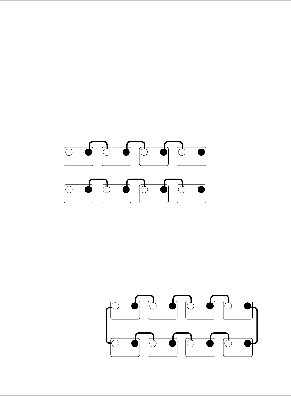
Battery Information
B–10 975-0012-01-02 Rev A
Wiring Batteries in Series-Parallel
Effect Wiring the batteries in a series-parallel configuration increases the current and
voltage of the battery bank. “Series-parallel” wiring is more complicated and care
should be taken when wiring these banks.
Steps It is done in three steps; wiring the batteries in series, wiring them in parallel, then
wiring the string to the inverter.
Series wiring To wire in series:
1. First wire the batteries in “series” (voltage adds) with the positive terminal of
one battery connected to the negative terminal of the next battery to meet the
inverter’s DC input requirements (24 volts shown in Figure B-4 and Figure
B-5.)
2. Repeat this step for the next battery string.
Two identical strings of batteries are now wired in series.
Parallel wiring To wire the batteries in parallel:
1. Connect the positive terminal of the first battery string to the positive terminal
of the second battery string.
2. Connect the negative terminal of the first battery string to the negative
terminal of the second battery string.
Figure B-4
Battery Wiring 24-volt - Parallel Configuration - Step 1
+–+–
6 V 6 V
+–+–
6 V 6 V
+–+–
6 V 6 V
+–+–
6 V 6 V
Series String 1
Series String 2
Each battery's amp-hour
rating is 100 Ah.
Figure B-5
Battery Wiring 24-volt - Parallel Configuration - Step 2
–+–
6 V 6 V
+–+–
6 V 6 V
+–+–
6 V 6 V
+–+–
6 V 6 V
+
Parallel
Connection
Series String 1
Series String 2
Parallel
Connection
Each battery's amp-hour
rating is 100 Ah.
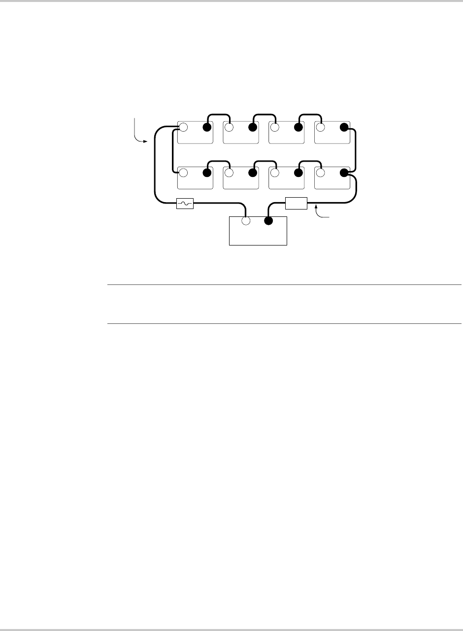
Battery Configurations
975-0012-01-02 Rev A B–11
Connect to inverter To connect to the inverter:
1. Connect a cable from the positive terminal of the first battery string to the
inverter’s positive DC terminal (via a fused device).
2. Connect the negative terminal of the last battery string to the negative
terminal of inverter’s DC terminal.
Figure B-6
Battery Wiring 24-volt - Parallel Configuration - Step 3
Important:
Connecting the positive and negative wires to the inverter from different
strings ensures a balanced charge/discharge through the batteries, resulting in longer run
times and improved battery life.
–+–
6 V 6 V
+–+–
6 V 6 V
+
6 V 6 V
–
6 V 6 V
+–
24 V INVERTER
(Tot al bat tery capacit y = 200 Ah)
–+–+–+
+
Connection from Series String 2 to
inverter's negative (–) terminal
Series String 2
Series String 1
Connection from Series String 1
to inverter's positive (+) terminal
Each battery's amp-hour
rating is 100 Ah.
SHUNT
DC Disconnect (can be
either a circuit breaker or a
fuse with a disconnect)
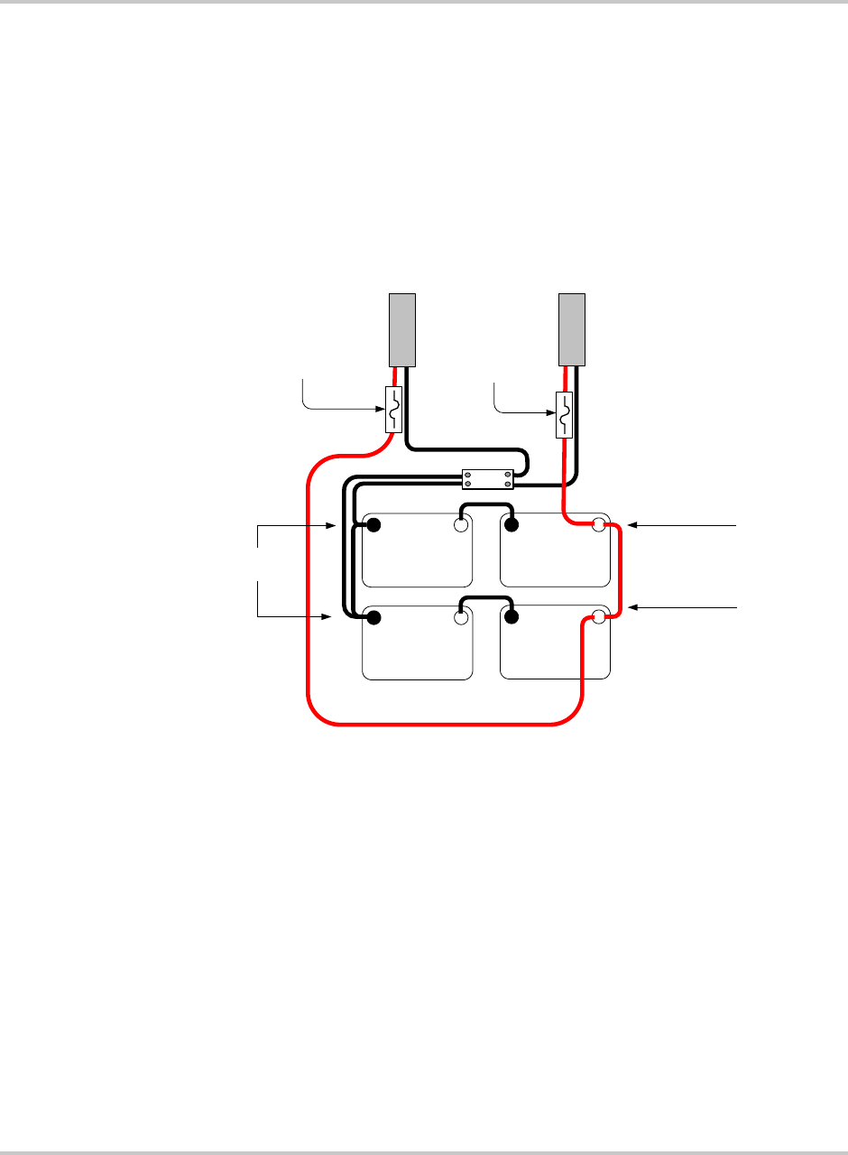
Battery Information
B–12 975-0012-01-02 Rev A
Battery Connections for Stacked Inverters
When using inverters in a stacked configuration, the same battery bank must be
used for both inverters. To ensure even charging of the batteries, each inverter
must be connected to both strings (i.e., positive cable to string two, and negative
cable to string one for inverter 1, and positive cable to string one and negative
cable to string two for inverter 2) as shown in the diagram below.
Figure B-7
Example of Battery Connections for Stacked Inverters (24 Vdc
shown)
DC CONDUIT
FOR
INVERTER 1
(Primary)
–+
12 Volt
Battery
200 Ah
–+
12 Volt
Battery
200 Ah
+–
12 Volt
Battery
200 Ah
Series String 1
Series String 2
DC CONDUIT
FOR
INVERTER 2
(Secondary)
24 VDC/200 Ah
24 VDC/200 Ah
–+
12 Volt
Battery
200 Ah
Shunt
Batteries in
Parallel
24 VDC 400 Ah
DC Disconnect
(either a circuit
breaker or a
fuse with a
disconnect)
DC Disconnect
(either a circuit
breaker or a
fuse with a
disconnect)

Battery Maintenance
975-0012-01-02 Rev A B–13
Battery Maintenance
Maintenance
strategy
To get the best performance from an inverter system, the batteries must be
properly setup and maintained. This includes setting the proper voltages for Bulk
and Float charging. See the “CAUTIONS” in the section on Equalization
Charging that follows. In addition, the battery terminals should be inspected,
cleaned, and re-torqued if necessary.
Neglecting any of these items may result in poor inverter performance and greatly
reduce battery life.
Battery Charging
Charge Rate The maximum safe charge rate is related to the size and type of the batteries.
Flooded lead acid batteries (with removable caps) can be charged at a high rate.
Small batteries may require a lower charge rate. Check with your battery vendor
for the proper battery charging rate for the batteries used in the system.
Bulk Voltage This is the maximum voltage the batteries will be charged to during a normal
charge cycle. Gel cell batteries are set to a lower value and non-sealed batteries
are set to a higher voltage setting.
Float Voltage The Float voltage is set lower than the Bulk voltage and provides a maintenance
charge on the batteries to keep them in a ready state.
Temperature
Compensation
For optimal battery charging, the Bulk and Float charge rates should be adjusted
according to the temperature of the battery. This can be accomplished
automatically by using a BTS. The sensor attaches directly to the side of one of
the batteries in the bank and provides precise battery temperature information.
When battery charging voltages are compensated based on temperature, the
charge voltage will vary depending on the temperature around the batteries. The
following table describes approximately how much the voltage may vary
depending on the temperature of the batteries.
If you have liquid lead acid batteries (non-sealed), you may need to periodically
equalize your batteries. Check the water level monthly to maintain it at the
appropriate level.

Battery Information
B–14 975-0012-01-02 Rev A
Temperature compensation is based on battery type — 5 mv/cell for lead acid type
batteries and 2 mv/cell for alkaline type batteries (NiCad or NiFe). The
temperature compensation calculations are derived from Table B-5.
Table B-4
Variances in Charging Voltage based on Battery Temperature
Temperature
(around the BTS) 12-volt units 24-volt units 48-volt units
Celsius Fahrenheit
Lead Acid
(6 cells)
NiCad
(10 cells)
Lead Acid
(12 cells)
NiCad
(20 cells)
Lead Acid
(24 cells)
NiCad
(40 cells)
60 140 -1.05 -0.70 -2.10 -1.40 -4.20 -2.80
55 131 -0.90 -0.60 -1.80 -1.20 -3.60 -2.40
50 122 -0.75 -0.50 -1.50 -1.00 -3.00 -2.00
45 113 -0.60 -0.40 -1.20 -0.80 -2.40 -1.60
40 104 -0.45 -0.30 -0.90 -0.60 -1.80 -1.20
35 95 -0.30 -0.20 -0.60 -0.40 -1.20 -0.80
30 86 -0.15 -0.10 -0.30 -0.20 -0.60 -0.40
25 77 0.00 0.00 0.00 0.00 0.00 0.00
20 68 0.15 0.10 0.30 0.20 0.60 0.40
15 59 0.30 0.20 0.60 0.40 1.20 0.80
10 50 0.45 0.30 0.90 0.60 1.80 1.20
5 41 0.90 0.60 1.20 0.80 2.40 1.60
0 32 0.75 0.50 1.50 1.00 3.00 2.00
-5 23 0.90 0.60 1.80 1.20 3.60 2.40
-10 14 1.05 1.20 2.10 1.40 4.20 2.80
-15 5 1.20 0.80 2.40 1.60 4.80 3.20
-20 -4 1.35 1.40 2.70 1.80 5.40 3.60
-25 -13 1.50 1.00 3.00 2.00 6.00 4.00
-30 -22 1.65 1.10 3.30 2.20 6.60 4.40
-35 -31 1.80 1.20 3.60 2.40 7.20 4.80
-40 -40 1.95 1.30 3.90 2.60 7.80 5.20
Table B-5
Temperature Compensation Calculation
Battery Type 24-volt Systems 48-volt Systems
Lead Acid 0.060 volts (60 mV) per
degree Celsius
0.120 Volts (120 mV) per degree
Celsius
NiCad 0.040 volts (40 mV) per
degree Celsius
0.080 volts (80 mV) per degree
Celsius
Important:
If the battery temperature is allowed to fall to extremely cold
temperatures, the inverter with a BTS may not be able to properly recharge cold
batteries due to maximum voltage limits of the inverter. Ensure the batteries are
protected from extreme temperatures.
Battery Maintenance
975-0012-01-02 Rev A B–15
Equalization Charging
Purpose An equalize charge helps to remove sulfate buildup on the battery plates and
balances the charge of individual cells.
Effect Equalize charging also produces gassing which stirs up the electrolyte mixture
and helps distribute the acid more evenly.
Non-equalized
batteries
Batteries that are not equalize charged can be damaged by sulfate accumulation,
thus sealing off a percentage of the plates and reducing battery capacity. They may
also have sulfuric acid accumulate at the bottom of the battery, potentially
damaging the plates. At the same time, the electrolyte at the top of the battery gets
watery. This effect is called stratification.
Frequency Every month or two the batteries should be equalize charged.
CAUTION: Damage to DC Loads
The high voltages reached during an equalize charge may damage DC loads that
are connected to the inverter. Disconnect any DC loads from the inverter before
running an equalize charge.
CAUTION: Damage to Batteries
Equalization should be done for standard electrolyte vented batteries only. Sealed
or GEL cell batteries should not be equalize charged. Consult your battery
supplier for details on equalize charging for the battery type in your system.
Battery Information
B–16 975-0012-01-02 Rev A
General Maintenance
Water Levels Flooded lead acid batteries require periodic water refills in each battery cell. Only
distilled water should be used in a battery, as tap or mineral water may contain
contaminants which will upset the battery chemistry and may damage the battery.
When filling the battery, clean the surface first to prevent dirt from entering the
cell. Fill the cell to just above the plates or to the bottom of the internal collar
inside the battery. Never fill the cells to the top or acid will leak out during
charging.
Check the water level in the batteries frequently when performing an equalize
charge and add water if necessary. Always follow the safety steps covered in the
front of the manual.
Battery Cables and
Posts
Battery posts must be clean to reduce the resistance between the battery post and
cable connection. A buildup of dirt or oxidation may eventually lead to the cable
terminal overheating during periods of high current draw.
Use a stiff wire brush and remove all dirt and corrosion from the battery terminals
and cables. Use an alkaline solution of baking soda and water to clean the
terminals and neutralize any battery acid on the terminals or cable lugs.
Torque Battery
Connections
After the terminals are clean, reassemble the cable to the battery terminal and
torque the connections to the battery manufacturer’s recommendations.
Coat the battery terminals with an antioxidant compound.
WARNING: Shock Hazard
Before attempting to clean the battery posts, turn off the DC circuit breaker. Use
only insulated tools and remove all jewellery.
CAUTION: Damage to Batteries
Never let a baking soda solution get into the battery as it will neutralize the acid
resulting in permanent damage.

Battery Maintenance
975-0012-01-02 Rev A B–17
State of Charge The battery’s state-of-charge should be checked often and only when the battery at
a state of rest (when the battery is not powering loads or actively being charged).
First thing in the morning is usually the best time to check the state of charge. If
the batteries are readily accessible, measure the voltage across the individual
battery terminals. There should be less than a 0.2 volt difference between each
battery.
To determine the individual cell voltage, divide the voltage by the number of cells
in the battery (25.2 volts divided by 12 cells = 2.1 volts per cell). If a greater
difference is measured, the batteries may need to be equalized (liquid lead-acid
types only) or replaced.
All batteries in the bank should measure the same voltage (this is not an accurate
measurement for cross-tied batteries’ as each battery is in parallel with another
battery making individual battery measurements impossible).
The voltage should match the following table for the entire battery bank output.
These values indicate the overall battery’s state of charge for the entire bank.
Individual cell voltages (if available) are also shown as a percentage of charge.
The values given are for a temperature of 77 °F (25 °C). Cooler temperatures
produce lower voltage measurements.
Table B-6
Battery State-of-Charge
System Voltage
Percent of Full
Charge 12 Volt 24 Volt 48 Volt
Individual
Cell
Voltage
100% 12.7 25.4 50.8 2.12
90% 12.6 25.2 50.4 2.10
80% 12.5 25.0 50.0 2.08
70% 12.3 24.6 49.2 2.05
60% 12.2 24.4 48.8 2.03
50% 12.1 24.2 48.4 2.02
40% 12.0 24.0 48.0 2.00
30% 11.8 23.6 47.2 1.97
20% 11.7 23.4 46.8 1.95
10% 11.6 23.2 46.4 1.93
0% < 11.6 < 23.2 < 46.4 < 1.93
Important:
Table B-6 only applies for batteries that have been at rest for a minimum of
3 hours (i.e., no inverting, no charging).
B–18

CMulti-wire Branch Circuit
Wiring
Appendix C, “Multi-wire Branch Circuit Wiring” supplies
information about Multi-wire Branch Circuit Wiring Precautions
when using stand-alone 120 Vac inverters or generators.
WARNING
A possible fire hazard can exist if 120 Vac only sources (such as inverters and
generators) are wired incorrectly into 120/240 Vac panels containing multi-wire
branch circuits. This section describes how to check for multi-wire branch
circuits in the load center and presents some possible solutions to this wiring
method.
Multi-wire Branch Circuit Wiring
C–2 975-0012-01-02 Rev A
Multi-wire Branch Circuits
Problem A potential safety problem exists when installing stand-alone 120 Vac inverters
into existing 120/240 Vac wired panels where multi-wire branch circuit wiring
methods were used.
Legacy situation Multi-wire branch circuits are wired differently from “home run” type wiring
(Figure C-1) in that only one neutral wire is used to provide the neutral-return path
for each circuit connected to both phases of the AC grid. This method has been
employed by electricians in recent years to keep construction costs down by
saving copper and labor costs involved in running a separate Romex™ for each
circuit.
Normal condition Under normal conditions, this technique is quite safe and meets code
requirements. When used as originally installed, the current for each circuit is
180° out-of-phase with each other, so the neutral wire never receives more current
than it was designed to handle as the current from each circuit subtracts (or
cancels out, leaving only the difference current between the two circuits). Refer to
Figure C-2.
Safety issue A safety problem occurs when a stand-alone 120 Vac inverter is installed to power
these circuits, causing the one neutral wire to now carry the in-phase currents for
both circuits. Since the current is in-phase, the two circuits add instead of subtract,
potentially doubling the current flow in the neutral return wire! Refer to Figure
C-3. The branch circuit breakers do not protect the neutral wire from overload
under this condition. This excess current will overheat the neutral wire, potentially
creating a fire hazard.
Figure C-1
Conventional Home-type Wiring
Load Center
L1
L2
Neutral
Ground
120 Vac
15 A
Breaker
15 A
Bre ake r
240 Vac
from Grid
Bare - Ground
White - Ne utral
(Current Flow 15 A)
Black - Hot
(Current Flow 15A)
120 Vac
Black - Hot
(Current Flow 15A)
White - Ne utral
(Current Flow 15 A)
Bare - Ground
Multi-wire Branch Circuits
975-0012-01-02 Rev A C–3
Figure C-2
Multi-wire Branch Circuit Wiring and Current Flow
Figure C-3
120 Vac Inverter Incorrectly Wired in a Multi-wire Branch Circuit
Load Center
L1
L2
Neutral
Ground
120 Vac 120 Vac
15 A
Breaker
(Ganged)
240 Vac
f
rom Grid
Bare - Ground
Single White - Neutral
(Current Flow 0 A)
Black - Hot
(Current Flow 15 A)
Red - Hot
(Current Flow 15 A)
Bare - Ground Splice
White - Neutral Splice
(Current Flow 15 A)
Out-of-Phase current
subtract at this point
(Current Flow 0 A)
15 A
Breaker
(Ganged)
Load Center
L1
L2
Neutral
Ground
120 Vac 120 Vac
15 A
Breaker
(Ganged)
240 Vac
from Grid
Bare - Ground
Single White - Neutral
(Current Flow 10 A)
Black - Hot
(Current Flow 5 A)
Red - Hot
(Current Flow 15 A)
White - Neutral Splice
(Current Flow 15 A)
When unbalanced
current flows through
each leg, only the
difference current
flows through the
neutral return wire.
15 A
Breaker
(Ganged)
Load Center
L1
L2
Neutral
Ground
120 Vac 120 Vac
15 A
Breaker
(Ganged)
Bare - Ground
Single White - Neutral
(Current Flow 30 A)
Black - Hot
(Current Flow 15 A)
Red - Hot
(Current Flow 15 A
White - Neutral Splice
(Current Flow 15 A)
WARNING: FIRE HAZARD
The in-phase currents ADDS
at this point exceeding wire
capacity!
15 A
Breaker
(Ganged)
120 Vac
Inverter or Generator
Multi-wire Branch Circuit Wiring
C–4 975-0012-01-02 Rev A
Identifying Multi-wire Branch Circuits
Identifying
characteristic
Multi-wire branch circuits can be identified by removing the cover on the load
center and inspecting the wiring. Conventional 120 Vac circuits are identified by a
2-wire-plus-ground (black, white, and copper) “romex” for each circuit.
Multi-wire branch circuits use a 3-wire-plus-ground arrangement (black, red,
white and copper) for each circuit run.
If this arrangement exists in the panel and it is being powered by a stand-alone
120 Vac inverter, a potential fire hazard exists! For safety, these circuits must be
rewired to meet code.
WARNING: Shock Hazard
The next step involves opening the load center, exposing live circuits. This
procedure should only be performed by qualified persons or electricians.
Figure C-4
Multi-wire Branch Circuit Wiring
Ground Bare
Copper
Single Neutral
White
Red From L2
Breaker
Red From L1
Breaker
To Branch Circuits
Correcting Multi-wire Branch Circuit Wiring
975-0012-01-02 Rev A C–5
Correcting Multi-wire Branch Circuit Wiring
Acceptable options Correcting multi-wire branch circuit wiring is not easy. Two options which will
correct multi wiring branch circuit wiring are:
• Rewire existing multi-wire branch circuits to conventional “home run”
wiring. This requires a qualified electrician (knowledgeable about multi-wire
branch circuit wiring) and is expensive. There may be multiple multi-wire
branch circuits located throughout the structure, requiring complete rewiring.
• Add a second inverter in a “series stacked” arrangement. This is an expensive
solution, but would restore the original 240 Vac split-phase configuration.
This solution may actually be less expensive than having an electrician
re-wire the multi-wire branch circuits. It also provides increased power
backup protection and can power 240 Vac loads.
Recommended
option
Add a step-down autotransformer to the output of the inverter to restore the
split-phase configuration. This is the least expensive and easiest method to correct
for multi-wire branch circuit wiring. Refer to Figure C-5. Using this method, half
of the current is supplied to one leg of the circuit and half to the other in a
split-phase arrangement (180° out-of-phase). This will restore the original
functionality and safety to the multi-wire branch circuit.
WARNING: Fire Hazard
Until one of the solutions above is implemented, a stand-alone 120 Vac inverter
(or generator) must not be installed where multi-wire branch circuits exist.
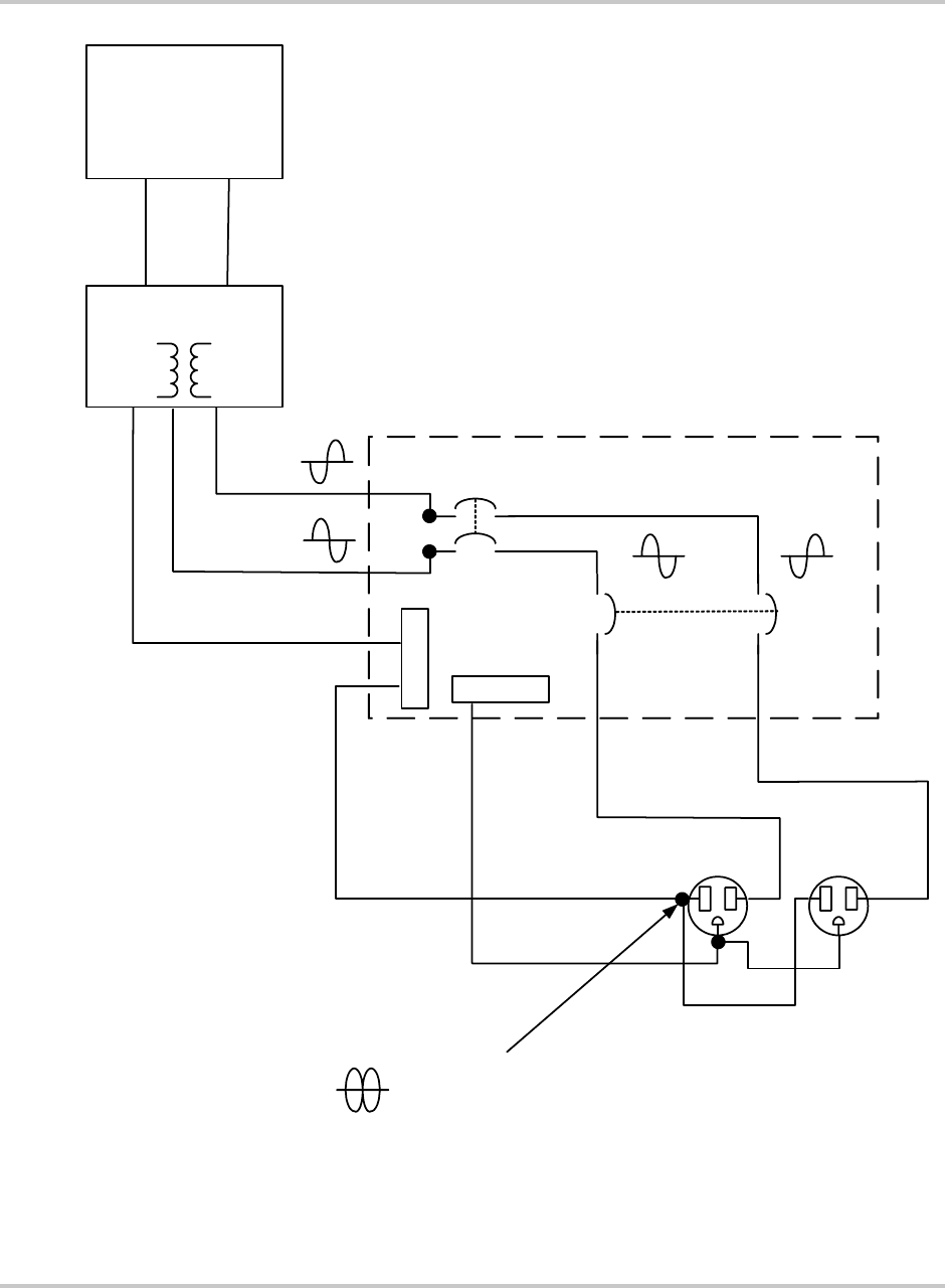
Multi-wire Branch Circuit Wiring
C–6 975-0012-01-02 Rev A
Figure C-5
Using a Step-down Autotransformer in Multi-wire Branch Circuit Wiring
Load Center
L1
L2
Neutral
Ground
120 Vac 120 Vac
15 A
Breaker
(Ganged)
Bare - Ground
Single White - Neutral
(Current Flow 0 A)
Black - Hot
(Current Flow 15 A)
Red - Hot
(Current Flow 15 A
White - Neutral Splice
(Current Flow 15 A)
15 A
Breaker
(Ganged)
T240
AutoTransformer
White - Neutral
HOT - L2
HOT - L1
HOT
NEUTRAL
The out-of-phase
current SUBTRACTS
at this point.
120 Vac
Inverter or Generator

975-0012-01-02 Rev A WA–1
Warranty and Return Information
Warranty
What does this warranty cover? This Limited Warranty is provided by Xantrex Technology, Inc. ("Xantrex")
and covers defects in workmanship and materials in your DR Inverter/Charger. This warranty period lasts for
Warranty period from the date of purchase at the point of sale to you, the original end user customer. You require
proof of purchase to make warranty claims.
This Limited Warranty is transferable to subsequent owners but only for the unexpired portion of the Warranty
Period. Subsequent owners also require proof of purchase.
What will Xantrex do?
Xantrex will, at its option, repair or replace the defective product free of charge, provided that you notify Xantrex of
the product defect within the Warranty Period, and provided that Xantrex through inspection establishes the existence
of such a defect and that it is covered by this Limited Warranty.
Xantrex will, at its option, use new and/or reconditioned parts in performing warranty repair and building
replacement products. Xantrex reserves the right to use parts or products of original or improved design in the repair
or replacement. If Xantrex repairs or replaces a product, its warranty continues for the remaining portion of the
original Warranty Period or 90 days from the date of the return shipment to the customer, whichever is greater. All
replaced products and all parts removed from repaired products become the property of Xantrex.
Xantrex covers both parts and labor necessary to repair the product, and return shipment to the customer via a
Xantrex-selected non-expedited surface freight within the contiguous United States and Canada. Alaska and Hawaii
are excluded. Contact Xantrex Customer Service for details on freight policy for return shipments outside of the
contiguous United States and Canada.
How do you get service? If your product requires troubleshooting or warranty service, contact your merchant. If
you are unable to contact your merchant, or the merchant is unable to provide service, contact Xantrex directly at:
Direct returns may be performed according to the Xantrex Return Material Authorization Policy described in your
product manual. For some products, Xantrex maintains a network of regional Authorized Service Centers. Call
Xantrex or check our website to see if your product can be repaired at one of these facilities.
What proof of purchase is required? In any warranty claim, dated proof of purchase must accompany the
product and the product must not have been disassembled or modified without prior written authorization by Xantrex.
Proof of purchase may be in any one of the following forms:
• The dated purchase receipt from the original purchase of the product at point of sale to the end user, or
• The dated dealer invoice or purchase receipt showing original equipment manufacturer (OEM) status, or
• The dated invoice or purchase receipt showing the product exchanged under warranty
Telephone: 1 800 670 0707 (toll free North America)
1 360 925 5097 (direct)
Fax: 1 800 994 7828 (toll free North America)
1 360 925 5143 (direct)
Email: customerservice@xantrex.com

Warranty and Return
WA–2 975-0012-01-02 Rev A
What does this warranty not cover? This Limited Warranty does not cover normal wear and tear of the
product or costs related to the removal, installation, or troubleshooting of the customer's electrical systems. This
warranty does not apply to and Xantrex will not be responsible for any defect in or damage to:
a) the product if it has been misused, neglected, improperly installed, physically damaged or altered, either inter-
nally or externally, or damaged from improper use or use in an unsuitable environment;
b) the product if it has been subjected to fire, water, generalized corrosion, biological infestations, or input voltage
that creates operating conditions beyond the maximum or minimum limits listed in the Xantrex product specifi-
cations including high input voltage from generators and lightning strikes;
c) the product if repairs have been done to it other than by Xantrex or its authorized service centers (hereafter
"ASCs");
d) the product if it is used as a component part of a product expressly warranted by another manufacturer;
e) the product if its original identification (trade-mark, serial number) markings have been defaced, altered, or
removed.
Disclaimer
Product
THIS LIMITED WARRANTY IS THE SOLE AND EXCLUSIVE WARRANTY PROVIDED BY XANTREX IN CONNECTION WITH YOUR
XANTREX PRODUCT AND IS, WHERE PERMITTED BY LAW, IN LIEU OF ALL OTHER WARRANTIES, CONDITIONS,
GUARANTEES, REPRESENTATIONS, OBLIGATIONS AND LIABILITIES, EXPRESS OR IMPLIED, STATUTORY OR OTHERWISE IN
CONNECTION WITH THE PRODUCT, HOWEVER ARISING (WHETHER BY CONTRACT, TORT, NEGLIGENCE, PRINCIPLES OF
MANUFACTURER'S LIABILITY, OPERATION OF LAW, CONDUCT, STATEMENT OR OTHERWISE), INCLUDING WITHOUT
RESTRICTION ANY IMPLIED WARRANTY OR CONDITION OF QUALITY, MERCHANTABILITY OR FITNESS FOR A PARTICULAR
PURPOSE. ANY IMPLIED WARRANTY OF MERCHANTABILITY OR FITNESS FOR A PARTICULAR PURPOSE TO THE EXTENT
REQUIRED UNDER APPLICABLE LAW TO APPLY TO THE PRODUCT SHALL BE LIMITED IN DURATION TO THE PERIOD
STIPULATED UNDER THIS LIMITED WARRANTY.
IN NO EVENT WILL XANTREX BE LIABLE FOR ANY SPECIAL, DIRECT, INDIRECT, INCIDENTAL OR CONSEQUENTIAL
DAMAGES, LOSSES, COSTS OR EXPENSES HOWEVER ARISING WHETHER IN CONTRACT OR TORT INCLUDING WITHOUT
RESTRICTION ANY ECONOMIC LOSSES OF ANY KIND, ANY LOSS OR DAMAGE TO PROPERTY, ANY PERSONAL INJURY, ANY
DAMAGE OR INJURY ARISING FROM OR AS A RESULT OF MISUSE OR ABUSE, OR THE INCORRECT INSTALLATION,
INTEGRATION OR OPERATION OF THE PRODUCT.
Exclusions
If this product is a consumer product, federal law does not allow an exclusion of implied warranties. To the extent you
are entitled to implied warranties under federal law, to the extent permitted by applicable law they are limited to the
duration of this Limited Warranty. Some states and provinces do not allow limitations or exclusions on implied
warranties or on the duration of an implied warranty or on the limitation or exclusion of incidental or consequential
damages, so the above limitation(s) or exclusion(s) may not apply to you. This Limited Warranty gives you specific
legal rights. You may have other rights which may vary from state to state or province to province.
Warning: Limitations On Use
Please refer to your product manual for limitations on uses of the product.
SPECIFICALLY, PLEASE NOTE THAT THE DR INVERTER/CHARGER SHOULD NOT BE USED IN CONNECTION WITH LIFE
SUPPORT SYSTEMS OR OTHER MEDICAL EQUIPMENT OR DEVICES. WITHOUT LIMITING THE GENERALITY OF THE
FOREGOING, XANTREX MAKES NO REPRESENTATIONS OR WARRANTIES REGARDING THE USE OF THE XANTREX DR
INVERTER/CHARGER IN CONNECTION WITH LIFE SUPPORT SYSTEMS OR OTHER MEDICAL EQUIPMENT OR DEVICES.
Please note that the DR Inverter/Charger is not intended for use as an uninterruptible power supply and Xantrex
makes no warranty or representation in connection with any use of the product for such purposes.

Warranty and Return
975-0012-01-02 Rev A WA–3
Return Material Authorization Policy
Before returning a product directly to Xantrex you must obtain a Return Material Authorization (RMA) number and
the correct factory "Ship To" address. Products must also be shipped prepaid. Product shipments will be refused and
returned at your expense if they are unauthorized, returned without an RMA number clearly marked on the outside of
the shipping box, if they are shipped collect, or if they are shipped to the wrong location.
When you contact Xantrex to obtain service, please have your instruction manual ready for reference and be prepared
to supply:
• The serial number of your product
• Information about the installation and use of the unit
• Information about the failure and/or reason for the return
• A copy of your dated proof of purchase
Record these details in on page WA–4.
Return Procedure
1. Package the unit safely, preferably using the original box and packing materials. Please ensure that your product
is shipped fully insured in the original packaging or equivalent. This warranty will not apply where the product is
damaged due to improper packaging.
2. Include the following:
• The RMA number supplied by Xantrex Technology, Inc. clearly marked on the outside of the box.
• A return address where the unit can be shipped. Post office boxes are not acceptable.
• A contact telephone number where you can be reached during work hours.
• A brief description of the problem.
3. Ship the unit prepaid to the address provided by your Xantrex customer service representative.
If you are returning a product from outside of the USA or Canada In addition to the above, you MUST
include return freight funds and are fully responsible for all documents, duties, tariffs, and deposits.
If you are returning a product to a Xantrex Authorized Service Center (ASC) A Xantrex return
material authorization (RMA) number is not required. However, you must contact the ASC prior to returning the
product or presenting the unit to verify any return procedures that may apply to that particular facility.
Out of Warranty Service
If the warranty period for your DR Inverter/Charger has expired, if the unit was damaged by misuse or incorrect
installation, if other conditions of the warranty have not been met, or if no dated proof of purchase is available, your
inverter may be serviced or replaced for a flat fee.
To return your DR Inverter/Charger for out of warranty service, contact Xantrex Customer Service for a Return
Material Authorization (RMA) number and follow the other steps outlined in “Return Procedure” on page WA–3.
Payment options such as credit card or money order will be explained by the Customer Service Representative. In
cases where the minimum flat fee does not apply, as with incomplete units or units with excessive damage, an
additional fee will be charged. If applicable, you will be contacted by Customer Service once your unit has been
received.

Warranty and Return
WA–4 975-0012-01-02 Rev A
Information About Your System
As soon as you open your DR Inverter/Charger package, record the following information and be sure to keep your
proof of purchase.
If you need to contact Customer Service, please record the following details before calling. This information will help
our representatives give you better service.
❐Serial Number _________________________________
❐Purchased From _________________________________
❐Purchase Date _________________________________
❐Type of installation (e.g. On-Grid, Off-grid) __________________________________
❐Length of time inverter has been installed __________________________________
❐Battery/battery bank size __________________________________
❐Battery type (e.g. flooded, sealed gel cell, AGM) __________________________________
❐DC wiring size and length __________________________________
❐Alarm sounding? __________________________________
❐Description of indicators on front panel __________________________________
❐Appliances operating when problem occurred __________________________________
❐Description of problem __________________________________
______________________________________________________________________________________
______________________________________________________________________________________
A
AM radios 4–3
AWG 2–4
B
Batteries
Battery Care and Maintenance
Equalization Charging B–15
Temperature Compensation B–13
Battery Types
Absorbed Glass Mat B–3
Flooded Lead Acid (FLA) B–2
Gel Cell B–3
Golf Cart B–2
Industrial (electric forklift) B–2
NiCad and NiFe B–3
Charging
Bulk Voltage B–13
Charge Rates B–13
Float Voltage B–13
batteries
first aid when working with vii
precautions when working with vii
Battery B–13
C
computers 4–3
computers - use with inverter 4–3
Customer Service
preparing to call WA–4
F
first aid vii
Fluorescent lights 4–4
I
Information about Your System form WA–4
inverter
purchase date WA–4
serial number WA–4
P
peak output voltage 4–4
Problem Loads 4–3
proof of purchase WA–4
purchase date WA–4
R
Reverse Polarity 2–18
S
safety instructions vii
serial number WA–4
W
warranty
out of warranty service WA–3
terms and conditions WA–1
X
Xantrex
web site iv
Index
IX-2

Xantrex Technology Inc.
1 800 670 0707 Tel. toll free NA
1 360 925 5097 Tel direct
1 800 994 7828 Fax toll free NA
1 360 925 5143 Fax direct
customerservice@xantrex.com
www.xantrex.com
975-0012-01-02 Rev A PC Printed in the DR
