Xantrex Pv225S 480 P Users Manual 152607_rev B
PV225S-480-P to the manual cfa5dc1f-f483-4ad3-b4fb-483c0f0dede0
2015-02-03
: Xantrex Xantrex-Pv225S-480-P-Users-Manual-473696 xantrex-pv225s-480-p-users-manual-473696 xantrex pdf
Open the PDF directly: View PDF ![]() .
.
Page Count: 126 [warning: Documents this large are best viewed by clicking the View PDF Link!]
PV225S 225 kW
Grid-Tied
Photovoltaic
Inverter
PV225S-480-P
Operation and Maintenance Manual

PV225S 225 kW Grid-Tied
Photovoltaic Inverter
Operation and Maintenance Manual
About Xantrex
Xantrex Technology Inc. is a world-leading supplier of advanced power electronics and controls with products from
50 watt mobile units to one MW utility-scale systems for wind, solar, batteries, fuel cells, microturbines, and backup
power applications in both grid-connected and stand-alone systems. Xantrex products include inverters, battery
chargers, programmable power supplies, and variable speed drives that convert, supply, control, clean, and distribute
electrical power.
Trademarks
PV225S 225 kW Grid-Tied Photovoltaic Inverter is a trademark of Xantrex International. Xantrex is a registered
trademark of Xantrex International.
Other trademarks, registered trademarks, and product names are the property of their respective owners and are used
herein for identification purposes only.
Notice of Copyright
PV225S 225 kW Grid-Tied Photovoltaic Inverter Operation and Maintenance Manual© August 2005 Xantrex
International. All rights reserved.
Disclaimer
UNLESS SPECIFICALLY AGREED TO IN WRITING, XANTREX TECHNOLOGY INC. (“XANTREX”)
(a) MAKES NO WARRANTY AS TO THE ACCURACY, SUFFICIENCY OR SUITABILITY OF ANY
TECHNICAL OR OTHER INFORMATION PROVIDED IN ITS MANUALS OR OTHER DOCUMENTATION.
(b) ASSUMES NO RESPONSIBILITY OR LIABILITY FOR LOSS OR DAMAGE, WHETHER DIRECT,
INDIRECT, CONSEQUENTIAL OR INCIDENTAL, WHICH MIGHT ARISE OUT OF THE USE OF SUCH
INFORMATION. THE USE OF ANY SUCH INFORMATION WILL BE ENTIRELY AT THE USER’S RISK.
Date and Revision
August 2005 Revision B
Part Number
152607
Contact Information
Telephone: 1 800 670 0707 (toll free North America)
1 360 925 5097 (direct)
Fax: 1 800 994 7828 (toll free North America)
1 360 925 5143 (direct)
Email: customerservice@xantrex.com
Web: www.xantrex.com

152607 iii
About This Manual
Purpose
The purpose of this Operation and Maintenance Manual is to provide explanations
and procedures for operating, maintaining, and troubleshooting the PV225S 225
kW Grid-Tied Photovoltaic Inverter. Installation instructions are available in the
PV225S 225 kW Grid-tied Photovoltaic Inverter Planning and Installation
Manual.
Scope
This Manual provides safety guidelines and information about operating and
troubleshooting the unit.
Audience
This Manual is intended for anyone who needs to operate the PV225S 225 kW
Grid-Tied Photovoltaic Inverter. Operators must be familiar with all the safety
regulations pertaining to operating high-voltage equipment as dictated by local
code. Operators must also have a complete understanding of this equipment’s
features and functions.
Organization
This Manual is organized into five chapters and one appendix.
Chapter 1, “Introduction” contains information about the features and functions of
the PV225S 225 kW Grid-Tied Photovoltaic Inverter.
Chapter 2, “Operation” contains information on the basic operation of the
PV225S 225 kW Grid-Tied Photovoltaic Inverter.
Chapter 3, “Commissioning” contains information on safely commissioning the
PV225S 225 kW Grid-Tied Photovoltaic Inverter.
Chapter 4, “Troubleshooting” contains information and procedures for
troubleshooting the PV225S 225 kW Grid-Tied Photovoltaic Inverter. It provides
descriptions of common situations and errors that may occur and provides
possible solutions for resolving fault conditions. It also provides instructions for
clearing faults manually, if required.
Chapter 5, “Preventative Maintenance” contains information and procedures for
performing preventative maintenance on the PV225S 225 kW Grid-Tied
Photovoltaic Inverter.
Appendix A provides the environmental and electrical specifications for the
PV225S 225 kW Grid-Tied Photovoltaic Inverter.

About This Manual
iv 152607
Conventions Used
The following conventions are used in this guide.
This Manual contains information for the PV225S-480-P 225 kW Grid-Tied
Photovoltaic Inverter. Throughout the manual it will be referred to as the PV225S,
unless otherwise noted.
WARNING
Warnings identify conditions or practices that could result in personal injury or loss of life.
CAUTION
Cautions identify conditions or practices that could result in damage to the unit or other
equipment.
Important:
These notes describe things which are important for you to know, but not as
serious as a caution or warning.

About This Manual
152607 v
Abbreviations and Acronyms
CCU2 Converter Control Unit 2
CFM Cubic Feet per Minute
CW Clockwise
DSP Digital Signal Processor
FPGA Field Programmable Gate Array
GUI Graphical User Interface
IEEE Institute of Electrical and Electronics Engineers
IGBT Insulated Gate Bipolar Transistor
IPM Intelligent Power Module
kcmil 1000 circular mils
LAN Local Area Network
POTS Plain Old Telephone Service
PSL Phase-Shift Loop
PV Photovoltaic
UFCU Universal Frontpanel Control Unit
Related Information
You can find more information about Xantrex Technology Inc. as well as its
products and services at www.xantrex.com.
vi
152607 vii
Important Safety Instructions
SAVE THESE INSTRUCTIONS - DO NOT DISCARD
This manual contains important safety instructions for the PV225S that must be
followed during installation and maintenance procedures.
WARNING: Shock Hazard
Read and keep this Operation and Maintenance Manual for future reference.
Before installing the PV225S, read all instructions, cautionary markings, and all other
appropriate sections of this manual. Failure to adhere to these warnings could result in
severe shock or possible death. Exercise extreme caution at all times to prevent accidents.
WARNING: Shock Hazard
The PV225S enclosures contain exposed high voltage conductors. The enclosure doors
should remain closed with the latches tightened, except during maintenance or testing.
These servicing instructions are for use by qualified personnel who meet all local and state
code requirements for licensing and training for the installation of Electrical Power
Systems with AC and DC voltage to 600 volts. To reduce the risk of electric shock, do not
perform any servicing other than that specified in the installation instructions unless you
are qualified to do so. Do not open the cabinet doors if extreme moisture is present (rain or
heavy dew).
WARNING: Lethal Voltage
In order to remove all sources of voltage from the PV225S, the incoming power must be
de-energized at the source. This may be done at the main utility circuit breaker and by
opening the AC Disconnect and the DC Disconnect Switches on the PV225S. Review the
system configuration to determine all of the possible sources of energy. In addition, allow
5 minutes for the DC bus capacitors, located on the ceiling of the cabinet, to discharge
after removing power.

Safety
viii 152607
General Safety Precautions
1. When installing the PV225S use only components recommended or sold by
Xantrex. Doing otherwise may result in a risk of fire, electric shock, injury to
persons, and will void the warranty.
2. Do not attempt to operate the PV225S if it has been dropped, or received more
than cosmetic damage during transport or shipping. If the PV225S is
damaged, or suspected to be damaged, see the Warranty section of this
manual.
3. To reduce the risk of electrical shock, lock-out and tag the PV225S before
attempting any maintenance, service, or cleaning.
Personal Safety
Follow these instructions to ensure your safety while working with the PV225S.
Safety Equipment
Authorized service personnel must be equipped with standard safety equipment
including the following:
• Safety glasses
• Ear protection
• Steel-toed safety boots
• Safety hard hats
• Padlocks and tags
• Appropriate meter to verify that the circuits are de-energized
(600 Vac and DC rated, minimum)
Check local safety regulations for other requirements.
Wiring Requirements
1. All wiring methods and materials shall be in accordance with the National
Electrical Code ANSI/NFPA 70. When sizing conductors and conduits
interfacing to the PV225S, both shall be in accordance with the National
Electric Code ANSI/NFPA 70, as well as all state and local code
requirements.
2. Use copper conductors only with insulation rated for 90 °C.
3. The PV225S has a three-phase output. It is marked with this symbol:
4. The AC power conductor wiring interfacing with the AC terminals in the
Transformer Enclosure are located at T6-X1, T6-X2, and T6-X3. These
terminals should be tightened to a torque value of 420 in-lb (47.5 Nm).
Conductors terminated to these terminals must use a crimp-on type ring

Safety
152607 ix
terminal or compression lug. The terminals can accommodate up to two
conductors per phase. See the PV225S 225 kW Grid-tied Photovoltaic Inverter
Planning and Installation Manual for the location of these terminals.
5. The AC power conductor wiring interfacing with the AC terminals in the
Main Inverter Enclosure are located at TB5, TB6, and TB7. These terminals
are to be tightened to a torque value of 375 in-lb (42.4 Nm). The terminals
will accept a conductor size of 350 kcmil and can accommodate up to six
conductors per phase. See Figure 5-1 on page 5–4 for the location of these
terminals.
6. The AC power conductor wiring interfacing with the AC terminals in the
AC Interface Enclosure are located at S1-2T1, S1-4T2, and S1-6T3. These
terminals should be tightened to a torque value of 310 in-lb (35.0 Nm). See
Figure 5-2 on page 5–4 for the location of these terminals. Also see the
cautionary note in the PV225S 225 kW Grid-tied Photovoltaic Inverter
Planning and Installation Manual regarding hardware length.
7. The AC neutral conductor from the utility is terminated in the AC Interface
Enclosure at the TB11 terminal. This terminal requires the use of a crimp-on
type ring terminal or compression-type lug and should be tightened to a
torque value of 228 in-lb (25.7 Nm). See Figure 5-2 on page 5–4 for the
location of these terminals.
8. The DC power conductor wiring interfacing with the DC terminals at S2-6,
K2-6T3, and TB4 are to be tightened to a torque value of 600 in-lbs
(67.8 Nm). These terminals will accept a conductor size of 600 kcmil, and
can accommodate up to four conductors per pole at S2-6 and K2-6T3 and up
to two conductors at TB4. Keep these cables together as much as possible and
ensure that both cables pass through the same knockout and conduit fittings,
thus allowing any inductive currents to cancel. See Figure 5-3 on page 5–5 for
the location of these terminals.
9. This product is intended to be installed as part of a permanently grounded
electrical system per the National Electric Code ANSI/NFPA 70. A copper
ground rod must be installed within three feet of the PV225S enclosure. This
is the single point earth ground for the inverter system. The single point
ground for the system is to be made at the AC ground bus bar (TB12) in the
AC Interface Enclosure. This terminal requires the use of a crimp-on type ring
terminal or compression-type lug and should be tightened to a torque value of
420 in-lb (47.5 Nm).
10. The equipment grounds on the PV225S is marked with this symbol:
11. AC overcurrent protection for the utility interconnect (Grid-tie) must be
provided by the installers as part of the PV225S installation.
CAUTION: Fire Hazard
In accordance with the National Electrical Code, ANSI/NFPA 70, connect only to a circuit
provided with 400 amperes maximum branch circuit overcurrent protection for the
PV225S.
Safety
x152607
Operational Safety Procedures
Never work alone when servicing this equipment. A team of two is required until
the equipment is properly de-energized, locked-out and tagged, and verified de-
energized with a meter.
Thoroughly inspect the equipment prior to energizing. Verify that no tools or
equipment have inadvertently been left behind.
Lockout and Tag
Safety requirements mandate that this equipment not be serviced while energized.
Power sources for the PV225S must be locked-out and tagged prior to servicing.
Each energy source should have a padlock and tag installed on each energy source
prior to servicing.
The PV225S can be energized from both the AC source and the DC source. To
ensure that the inverter is de-energized prior to servicing, lockout and tag the
PV225S using the following procedure.
1. Open, lockout, and tag the incoming power at the utility main circuit breaker.
2. Open, lockout, and tag the AC Disconnect Switch (S1) on AC interface
assembly. See Figure 1-8 on page 1–12 for the location of the AC Disconnect
Switch.
3. Open, lockout, and tag the DC Disconnect Switch (S2) on DC interface
assembly. See Figure 1-8 on page 1–12 for the location of the DC Disconnect
Switch.
4. Using a confirmed, accurate meter, verify all power to the inverter is de-
energized. A confirmed, accurate meter must be verified on a known voltage
before use. Ensure that all incoming energy sources are de-energized by
checking the following locations.
a) Inverter Terminals: TB5, TB6, TB7 (Phase A, B, C)
See Figure 5-1 on page 5–4.
b) Utility Terminals: Top of S1-2T1, S1-4T2, S1-6T3
See Figure 5-2 on page 5–4.
c) PV Terminals: Bottom of S2-6, K2-6T3, TB4 (PV+, PV-, GND)
See Figure 5-3 on page 5–5.
WARNING: Shock Hazard
Review the system schematic for the installation to verify that all available energy sources
are de-energized. DC bus voltage may also be present. Be sure to wait the full 5 minutes to
allow the capacitors to discharge completely.

Safety
152607 xi
De-Energize/Isolation Procedure
The following procedure should be followed to de-energize the PV225S for
maintenance.
To isolate the PV225S:
1. Turn the ON/OFF switch to the OFF position.
2. Open the DC Disconnect Switch.
3. Open the AC Disconnect Switch.
4. Open the utility connection circuit breaker.
5. Install lockout devices on the utility connection circuit breaker and DC
Disconnect Switch.
Interconnection Standards Compliance
The PV225S has been tested and listed by Underwriters Laboratories to be in
compliance with UL 1741 Static Inverters And Charge Controllers For Use In
Photovoltaic Power Systems, as well as IEEE-929-2000 Recommended Practice
For Utility Interface of Photovoltaic (PV) Systems.
IEEE-929-2000 provides guidance regarding equipment and functions necessary
to ensure compatible operation of photovoltaic systems which are connected in
parallel with the electric utility.
UL1741 is the standard applied by Underwriters Laboratory to the PV225S to
verify it meets the recommendations of IEEE-929-2000.
Refer to both documents for details of these recommendations and test
procedures.
WARNING
The terminals of the DC input may be energized if the PV arrays are energized. In
addition, allow 5 minutes for all capacitors within the main enclosure to discharge after
disconnecting the PV225S from AC and DC sources.
xii

152607 xiii
Important Safety Instructions
- - - - - - - - - - - - - - - - - - - - - - - - - - - - - - - - - - - - - - - - - - -vii
1
Introduction
Operation Features- - - - - - - - - - - - - - - - - - - - - - - - - - - - - - - - - - - - - - - - - - - - - - - - - - - - - - 1–2
Fixed Unity Power Factor Operation - - - - - - - - - - - - - - - - - - - - - - - - - - - - - - - - - - - - - - - 1–2
Peak Power Tracking - - - - - - - - - - - - - - - - - - - - - - - - - - - - - - - - - - - - - - - - - - - - - - - - - 1–3
Dynamic DC Minimum Operating Voltage - - - - - - - - - - - - - - - - - - - - - - - - - - - - - - - - - - 1–4
Utility Voltage/Frequency Fault Automatic Reset - - - - - - - - - - - - - - - - - - - - - - - - - - - - - - 1–4
Safety Features - - - - - - - - - - - - - - - - - - - - - - - - - - - - - - - - - - - - - - - - - - - - - - - - - - - - - - - - 1–5
Anti-Island Protection - - - - - - - - - - - - - - - - - - - - - - - - - - - - - - - - - - - - - - - - - - - - - - - - - 1–5
PV Ground Fault Detection - - - - - - - - - - - - - - - - - - - - - - - - - - - - - - - - - - - - - - - - - - - - - 1–5
DC Over-voltage Detection - - - - - - - - - - - - - - - - - - - - - - - - - - - - - - - - - - - - - - - - - - - - - 1–5
Physical Characteristics - - - - - - - - - - - - - - - - - - - - - - - - - - - - - - - - - - - - - - - - - - - - - - - - - - 1–6
Main Inverter Enclosure - - - - - - - - - - - - - - - - - - - - - - - - - - - - - - - - - - - - - - - - - - - - - - - 1–7
Power Distribution Panel - - - - - - - - - - - - - - - - - - - - - - - - - - - - - - - - - - - - - - - - - - - - 1–7
Converter Control Unit (CCU2) - - - - - - - - - - - - - - - - - - - - - - - - - - - - - - - - - - - - - - - 1–7
Power Electronics Matrices - - - - - - - - - - - - - - - - - - - - - - - - - - - - - - - - - - - - - - - - - - 1–7
Inductor Enclosure - - - - - - - - - - - - - - - - - - - - - - - - - - - - - - - - - - - - - - - - - - - - - - - - - - - 1–7
DC Interface Enclosure - - - - - - - - - - - - - - - - - - - - - - - - - - - - - - - - - - - - - - - - - - - - - - - - 1–8
Transformer Enclosure - - - - - - - - - - - - - - - - - - - - - - - - - - - - - - - - - - - - - - - - - - - - - - - - 1–8
AC Interface Enclosure - - - - - - - - - - - - - - - - - - - - - - - - - - - - - - - - - - - - - - - - - - - - - - - - 1–8
Communications Enclosure - - - - - - - - - - - - - - - - - - - - - - - - - - - - - - - - - - - - - - - - - - - - - 1–9
Operator Interface Controls- - - - - - - - - - - - - - - - - - - - - - - - - - - - - - - - - - - - - - - - - - - - - - - 1–10
Main Enclosure Door Interlock Switch - - - - - - - - - - - - - - - - - - - - - - - - - - - - - - - - - - - - 1–10
On/Off Switch - - - - - - - - - - - - - - - - - - - - - - - - - - - - - - - - - - - - - - - - - - - - - - - - - - - - - 1–11
AC and DC Disconnect Switches - - - - - - - - - - - - - - - - - - - - - - - - - - - - - - - - - - - - - - - - 1–12
Communication Features - - - - - - - - - - - - - - - - - - - - - - - - - - - - - - - - - - - - - - - - - - - - - - - - 1–12
System Status and Fault Reporting - - - - - - - - - - - - - - - - - - - - - - - - - - - - - - - - - - - - - - - 1–13
Data Logging - - - - - - - - - - - - - - - - - - - - - - - - - - - - - - - - - - - - - - - - - - - - - - - - - - - - - 1–13
Communication Methods - - - - - - - - - - - - - - - - - - - - - - - - - - - - - - - - - - - - - - - - - - - - - - - - 1–14
Universal Front Panel Control Unit (UFCU) - - - - - - - - - - - - - - - - - - - - - - - - - - - - - - - - - 1–14
PC Connection Methods - - - - - - - - - - - - - - - - - - - - - - - - - - - - - - - - - - - - - - - - - - - - - - 1–15
POTS Access - - - - - - - - - - - - - - - - - - - - - - - - - - - - - - - - - - - - - - - - - - - - - - - - - - - 1–16
Wireless Access - - - - - - - - - - - - - - - - - - - - - - - - - - - - - - - - - - - - - - - - - - - - - - - - - 1–16
Ethernet LAN Access - - - - - - - - - - - - - - - - - - - - - - - - - - - - - - - - - - - - - - - - - - - - - 1–17
Direct Access - - - - - - - - - - - - - - - - - - - - - - - - - - - - - - - - - - - - - - - - - - - - - - - - - - - 1–17
GUI Software Features - - - - - - - - - - - - - - - - - - - - - - - - - - - - - - - - - - - - - - - - - - - - - - - 1–18
Contents

Contents
xiv 152607
2
Operation
Description of System Operation- - - - - - - - - - - - - - - - - - - - - - - - - - - - - - - - - - - - - - - - - - - - 2–2
Overview - - - - - - - - - - - - - - - - - - - - - - - - - - - - - - - - - - - - - - - - - - - - - - - - - - - - - - - - - 2–2
Faults - - - - - - - - - - - - - - - - - - - - - - - - - - - - - - - - - - - - - - - - - - - - - - - - - - - - - - - - - - - 2–2
Operating States - - - - - - - - - - - - - - - - - - - - - - - - - - - - - - - - - - - - - - - - - - - - - - - - - - - - - - - 2–4
Power Tracking - - - - - - - - - - - - - - - - - - - - - - - - - - - - - - - - - - - - - - - - - - - - - - - - - - - - 2–4
Transition - - - - - - - - - - - - - - - - - - - - - - - - - - - - - - - - - - - - - - - - - - - - - - - - - - - - - - - - 2–4
Shutdown - - - - - - - - - - - - - - - - - - - - - - - - - - - - - - - - - - - - - - - - - - - - - - - - - - - - - - - - - 2–5
Fault - - - - - - - - - - - - - - - - - - - - - - - - - - - - - - - - - - - - - - - - - - - - - - - - - - - - - - - - - - - - 2–5
Manual Current - - - - - - - - - - - - - - - - - - - - - - - - - - - - - - - - - - - - - - - - - - - - - - - - - - - - - 2–5
Matrix Test - - - - - - - - - - - - - - - - - - - - - - - - - - - - - - - - - - - - - - - - - - - - - - - - - - - - - - - 2–5
Automatic Sleep Test - - - - - - - - - - - - - - - - - - - - - - - - - - - - - - - - - - - - - - - - - - - - - - - - - 2–5
Operator Interface- - - - - - - - - - - - - - - - - - - - - - - - - - - - - - - - - - - - - - - - - - - - - - - - - - - - - - 2–6
UFCU Keypad Operation and LCD Display - - - - - - - - - - - - - - - - - - - - - - - - - - - - - - - - - 2–6
LCD Display - Initialization Screen - - - - - - - - - - - - - - - - - - - - - - - - - - - - - - - - - - - - - - - 2–7
Standard Display - - - - - - - - - - - - - - - - - - - - - - - - - - - - - - - - - - - - - - - - - - - - - - - - - - - - 2–7
Menu Structure - - - - - - - - - - - - - - - - - - - - - - - - - - - - - - - - - - - - - - - - - - - - - - - - - - - - - 2–8
Read Menu - - - - - - - - - - - - - - - - - - - - - - - - - - - - - - - - - - - - - - - - - - - - - - - - - - - - - 2–9
Write Menu - - - - - - - - - - - - - - - - - - - - - - - - - - - - - - - - - - - - - - - - - - - - - - - - - - - -2–15
Commanding Goal State Changes - - - - - - - - - - - - - - - - - - - - - - - - - - - - - - - - - - - - - - - -2–20
Setting the Date and Time - - - - - - - - - - - - - - - - - - - - - - - - - - - - - - - - - - - - - - - - - - - - -2–21
Manual State Transitions - - - - - - - - - - - - - - - - - - - - - - - - - - - - - - - - - - - - - - - - - - - - - -2–22
Automatic State Transitions - - - - - - - - - - - - - - - - - - - - - - - - - - - - - - - - - - - - - - - - - - - -2–22
Auto-restart Feature - - - - - - - - - - - - - - - - - - - - - - - - - - - - - - - - - - - - - - - - - - - - - - - - - - - -2–23
Energize Procedure (Startup) - - - - - - - - - - - - - - - - - - - - - - - - - - - - - - - - - - - - - - - - - - - - - -2–24
Computer Communications with the PV225S - - - - - - - - - - - - - - - - - - - - - - - - - - - - - - - - - - -2–25
Installing the Graphic User Interface (GUI) Software - - - - - - - - - - - - - - - - - - - - - - - - - - -2–26
Minimum System Requirements - - - - - - - - - - - - - - - - - - - - - - - - - - - - - - - - - - - - - -2–26
Starting the Software Setup Program - - - - - - - - - - - - - - - - - - - - - - - - - - - - - - - - - - -2–26
Starting the Setup Program Using Autorun - - - - - - - - - - - - - - - - - - - - - - - - - - - - - - -2–26
Starting Setup Manually - - - - - - - - - - - - - - - - - - - - - - - - - - - - - - - - - - - - - - - - - - - -2–26
Starting Setup From a Command Prompt - - - - - - - - - - - - - - - - - - - - - - - - - - - - - - - -2–27
Model Specific Software Installation - - - - - - - - - - - - - - - - - - - - - - - - - - - - - - - - - - - - - -2–28
Running the GUI - - - - - - - - - - - - - - - - - - - - - - - - - - - - - - - - - - - - - - - - - - - - - - - - - - - -2–31
Remote/LAN Connection - - - - - - - - - - - - - - - - - - - - - - - - - - - - - - - - - - - - - - - - - - -2–31
Direct Connection - - - - - - - - - - - - - - - - - - - - - - - - - - - - - - - - - - - - - - - - - - - - - - - -2–32
GUI Configuration - Adding Inverters - - - - - - - - - - - - - - - - - - - - - - - - - - - - - - - - - -2–33
GUI Help - - - - - - - - - - - - - - - - - - - - - - - - - - - - - - - - - - - - - - - - - - - - - - - - - - - - - - - - -2–37

Contents
152607 xv
3
Commissioning
Commissioning Procedure - - - - - - - - - - - - - - - - - - - - - - - - - - - - - - - - - - - - - - - - - - - - - - - - 3–2
Starting the Commissioning Test File - - - - - - - - - - - - - - - - - - - - - - - - - - - - - - - - - - - - - - - - - 3–2
Serial Number - - - - - - - - - - - - - - - - - - - - - - - - - - - - - - - - - - - - - - - - - - - - - - - - - - - - - - 3–3
Verify AC Voltage - - - - - - - - - - - - - - - - - - - - - - - - - - - - - - - - - - - - - - - - - - - - - - - - - - - 3–3
Verify DC Voltage - - - - - - - - - - - - - - - - - - - - - - - - - - - - - - - - - - - - - - - - - - - - - - - - - - - 3–3
Inspect Inductor Enclosure - - - - - - - - - - - - - - - - - - - - - - - - - - - - - - - - - - - - - - - - - - - - - 3–4
Apply Grid Voltage - - - - - - - - - - - - - - - - - - - - - - - - - - - - - - - - - - - - - - - - - - - - - - - - - - 3–4
Front Panel Display - - - - - - - - - - - - - - - - - - - - - - - - - - - - - - - - - - - - - - - - - - - - - - - - - - 3–4
Establish Communications with the GUI - - - - - - - - - - - - - - - - - - - - - - - - - - - - - - - - - - - - 3–5
Confirm AC Operational Parameters - - - - - - - - - - - - - - - - - - - - - - - - - - - - - - - - - - - - - - - 3–5
Confirm DC Operational Parameters - - - - - - - - - - - - - - - - - - - - - - - - - - - - - - - - - - - - - - - 3–6
Confirm Power Tracker Configuration Operational Parameters - - - - - - - - - - - - - - - - - - - - - 3–6
Verify Door Interlock Functions - - - - - - - - - - - - - - - - - - - - - - - - - - - - - - - - - - - - - - - - - - 3–6
Matrix Test - - - - - - - - - - - - - - - - - - - - - - - - - - - - - - - - - - - - - - - - - - - - - - - - - - - - - - - - 3–6
Operate Inverter - - - - - - - - - - - - - - - - - - - - - - - - - - - - - - - - - - - - - - - - - - - - - - - - - - - - - 3–7
Completed Commissioning - - - - - - - - - - - - - - - - - - - - - - - - - - - - - - - - - - - - - - - - - - - - - 3–7
4
Troubleshooting
Faults and Fault Codes - - - - - - - - - - - - - - - - - - - - - - - - - - - - - - - - - - - - - - - - - - - - - - - - - - - 4–2
General Troubleshooting - - - - - - - - - - - - - - - - - - - - - - - - - - - - - - - - - - - - - - - - - - - - - - - - - 4–2
Clearing Faults Manually - - - - - - - - - - - - - - - - - - - - - - - - - - - - - - - - - - - - - - - - - - - - - - - - - 4–3
Fault Code Descriptions - - - - - - - - - - - - - - - - - - - - - - - - - - - - - - - - - - - - - - - - - - - - - - - - - - 4–4
5
Preventative Maintenance
Maintenance Safety - - - - - - - - - - - - - - - - - - - - - - - - - - - - - - - - - - - - - - - - - - - - - - - - - - - - - 5–2
Operational Safety Procedures - - - - - - - - - - - - - - - - - - - - - - - - - - - - - - - - - - - - - - - - - - - 5–2
De-Energize/Isolation Procedure - - - - - - - - - - - - - - - - - - - - - - - - - - - - - - - - - - - - - - - 5–2
Lockout and Tag - - - - - - - - - - - - - - - - - - - - - - - - - - - - - - - - - - - - - - - - - - - - - - - - - 5–3
Periodic Maintenance- - - - - - - - - - - - - - - - - - - - - - - - - - - - - - - - - - - - - - - - - - - - - - - - - - - - 5–6
Monthly Intervals or As Required - - - - - - - - - - - - - - - - - - - - - - - - - - - - - - - - - - - - - - - - - 5–6
Aluminum Extrusion Heatsinks - - - - - - - - - - - - - - - - - - - - - - - - - - - - - - - - - - - - - - - 5–6
Fan Operation - - - - - - - - - - - - - - - - - - - - - - - - - - - - - - - - - - - - - - - - - - - - - - - - - - - 5–6
Internal Circulation Fan - - - - - - - - - - - - - - - - - - - - - - - - - - - - - - - - - - - - - - - - - - - - - 5–6
Inductor Enclosure Cooling Fans - - - - - - - - - - - - - - - - - - - - - - - - - - - - - - - - - - - - - - 5–6
Six-month Intervals - - - - - - - - - - - - - - - - - - - - - - - - - - - - - - - - - - - - - - - - - - - - - - - - - - 5–7
Enclosure Seals - - - - - - - - - - - - - - - - - - - - - - - - - - - - - - - - - - - - - - - - - - - - - - - - - - 5–7
Electrical Connections - - - - - - - - - - - - - - - - - - - - - - - - - - - - - - - - - - - - - - - - - - - - - - 5–7
Inductor Enclosure - - - - - - - - - - - - - - - - - - - - - - - - - - - - - - - - - - - - - - - - - - - - - - - - 5–7

Contents
xvi 152607
A
Specifications
System Specifications - - - - - - - - - - - - - - - - - - - - - - - - - - - - - - - - - - - - - - - - - - - - - - - - - - - A–2
Environmental Specifications - - - - - - - - - - - - - - - - - - - - - - - - - - - - - - - - - - - - - - - - - - - A–2
Electrical Specifications - - - - - - - - - - - - - - - - - - - - - - - - - - - - - - - - - - - - - - - - - - - - - - - A–3
Over Voltage, Under Voltage and Frequency Ranges - - - - - - - - - - - - - - - - - - - - - - - - - - - A–3
Wire Gauge and Torque Requirements - - - - - - - - - - - - - - - - - - - - - - - - - - - - - - - - - - - - - A–4
Warranty and Product Information
- - - - - - - - - - - - - - - - - - - - - - - - - - - - - - - - - - WA–1
Index
- - - - - - - - - - - - - - - - - - - - - - - - - - - - - - - - - - - - - - - - - - - - - - - - - - - - - - - - - - - - - - - IX–1

152607 xvii
Figure 1-1 Maximum Peak Power Tracking - - - - - - - - - - - - - - - - - - - - - - - - - - - - - - - - - - - - - - 1–4
Figure 1-2 PV225S Major Components - - - - - - - - - - - - - - - - - - - - - - - - - - - - - - - - - - - - - - - - - 1–6
Figure 1-3 DC Interface Enclosure - - - - - - - - - - - - - - - - - - - - - - - - - - - - - - - - - - - - - - - - - - - - 1–8
Figure 1-4 AC Interface Enclosure and Transformer Enclosure - - - - - - - - - - - - - - - - - - - - - - - - - 1–9
Figure 1-5 PC Connections in the Communications Enclosure- - - - - - - - - - - - - - - - - - - - - - - - - - 1–9
Figure 1-6 PV225S Operator Interface Components- - - - - - - - - - - - - - - - - - - - - - - - - - - - - - - - 1–10
Figure 1-7 On/Off Switch (S3) - - - - - - - - - - - - - - - - - - - - - - - - - - - - - - - - - - - - - - - - - - - - - - 1–11
Figure 1-8 AC and DC Disconnect Switches- - - - - - - - - - - - - - - - - - - - - - - - - - - - - - - - - - - - - 1–12
Figure 1-9 LCD Display and UFCU Location - - - - - - - - - - - - - - - - - - - - - - - - - - - - - - - - - - - - 1–14
Figure 1-10 PC Connections in the Communications Enclosure- - - - - - - - - - - - - - - - - - - - - - - - - 1–15
Figure 1-11 POTS Access - - - - - - - - - - - - - - - - - - - - - - - - - - - - - - - - - - - - - - - - - - - - - - - - - - 1–16
Figure 1-12 Wireless Access - - - - - - - - - - - - - - - - - - - - - - - - - - - - - - - - - - - - - - - - - - - - - - - - 1–16
Figure 1-13 LAN Access- - - - - - - - - - - - - - - - - - - - - - - - - - - - - - - - - - - - - - - - - - - - - - - - - - - 1–17
Figure 1-14 Direct Access - - - - - - - - - - - - - - - - - - - - - - - - - - - - - - - - - - - - - - - - - - - - - - - - - - 1–17
Figure 2-1 Operating States Flow Chart - - - - - - - - - - - - - - - - - - - - - - - - - - - - - - - - - - - - - - - - - 2–3
Figure 2-2 The Universal Front Panel Control Unit (UFCU) and LCD - - - - - - - - - - - - - - - - - - - - 2–6
Figure 2-3 Initialization Screens - - - - - - - - - - - - - - - - - - - - - - - - - - - - - - - - - - - - - - - - - - - - - - 2–7
Figure 2-4 Operator Interface Menu Diagram - - - - - - - - - - - - - - - - - - - - - - - - - - - - - - - - - - - - - 2–8
Figure 2-5 Scrolling through the Read Menu - - - - - - - - - - - - - - - - - - - - - - - - - - - - - - - - - - - - 2–10
Figure 2-6 Read-by-ID Feature- - - - - - - - - - - - - - - - - - - - - - - - - - - - - - - - - - - - - - - - - - - - - - 2–13
Figure 2-7 State Transition Diagram - - - - - - - - - - - - - - - - - - - - - - - - - - - - - - - - - - - - - - - - - - 2–20
Figure 2-8 LCD showing Fault Code - - - - - - - - - - - - - - - - - - - - - - - - - - - - - - - - - - - - - - - - - - 2–23
Figure 2-9 GUI Interface Main Menu Screen - - - - - - - - - - - - - - - - - - - - - - - - - - - - - - - - - - - - 2–25
Figure 2-10 Staring Setup from a Command Prompt - - - - - - - - - - - - - - - - - - - - - - - - - - - - - - - - 2–27
Figure 2-11 GUI Splash Screen - - - - - - - - - - - - - - - - - - - - - - - - - - - - - - - - - - - - - - - - - - - - - - 2–28
Figure 2-12 GUI Setup Welcome Window - - - - - - - - - - - - - - - - - - - - - - - - - - - - - - - - - - - - - - - 2–28
Figure 2-13 GUI Setup Start Window - - - - - - - - - - - - - - - - - - - - - - - - - - - - - - - - - - - - - - - - - - 2–29
Figure 2-14 GUI Setup Program Group Window- - - - - - - - - - - - - - - - - - - - - - - - - - - - - - - - - - - 2–29
Figure 2-15 GUI Setup Progress Indicator Window - - - - - - - - - - - - - - - - - - - - - - - - - - - - - - - - - 2–30
Figure 2-16 GUI Setup Start Window - - - - - - - - - - - - - - - - - - - - - - - - - - - - - - - - - - - - - - - - - - 2–30
Figure 2-17 GUI Interface Screen if Connected Remotely - - - - - - - - - - - - - - - - - - - - - - - - - - - - 2–31
Figure 2-18 GUI Interface Screen if Connected Directly - - - - - - - - - - - - - - - - - - - - - - - - - - - - - 2–32
Figure 2-19 Detail Screen - - - - - - - - - - - - - - - - - - - - - - - - - - - - - - - - - - - - - - - - - - - - - - - - - - 2–33
Figure 2-20 Contact Screen - - - - - - - - - - - - - - - - - - - - - - - - - - - - - - - - - - - - - - - - - - - - - - - - - 2–33
Figure 2-21 Operational Configuration Screen - Limits - - - - - - - - - - - - - - - - - - - - - - - - - - - - - - 2–34
Figure 2-22 Operational Configuration Screen - PV- - - - - - - - - - - - - - - - - - - - - - - - - - - - - - - - - 2–34
Figure 2-23 Operational Configuration Screen - Power Tracker- - - - - - - - - - - - - - - - - - - - - - - - - 2–35
Figures

Figures
xviii 152607
Figure 2-24 Connection Configuration Screen - General - - - - - - - - - - - - - - - - - - - - - - - - - - - - - -2–35
Figure 2-25 Connection Configuration Screen - Telephone Fault Configuration - - - - - - - - - - - - - -2–36
Figure 2-26 Connection Configuration Screen - General - - - - - - - - - - - - - - - - - - - - - - - - - - - - - -2–36
Figure 2-27 GUI Interface Screen if Connected Directly - - - - - - - - - - - - - - - - - - - - - - - - - - - - - -2–37
Figure 4-1 LCD showing Fault Code - - - - - - - - - - - - - - - - - - - - - - - - - - - - - - - - - - - - - - - - - - 4–3
Figure 5-1 Inverter AC Terminal Locations in the Main Inverter Enclosure - - - - - - - - - - - - - - - - 5–4
Figure 5-2 Utility AC Terminal Connections in the AC Interface Enclosure - - - - - - - - - - - - - - - - 5–4
Figure 5-3 PV Terminal Locations - - - - - - - - - - - - - - - - - - - - - - - - - - - - - - - - - - - - - - - - - - - - 5–5
Figure A-1 Electrical Diagram (sample)- - - - - - - - - - - - - - - - - - - - - - - - - - - - - - - - - - - - - - - - - A–5
Figure A-2 PV225S Schematic for Main Power Distribution (152812 A1) - - - - - - - - - - - - - - - - - A–6
Figure A-3 PV225S Schematic for Control Power Distribution (152812 A2) - - - - - - - - - - - - - - - A–7
Figure A-4 PV225S Schematic for Converter Control Unit (152812 A3)- - - - - - - - - - - - - - - - - - - A–8

152607 xix
Table 2-1 Scrolling through the Read Menu Parameters - - - - - - - - - - - - - - - - - - - - - - - - - - - - - 2–9
Table 2-2 Read Menu Descriptions - - - - - - - - - - - - - - - - - - - - - - - - - - - - - - - - - - - - - - - - - - 2–11
Table 2-3 Data Logging Menu- - - - - - - - - - - - - - - - - - - - - - - - - - - - - - - - - - - - - - - - - - - - - - 2–14
Table 2-4 Accumulated Values Menu- - - - - - - - - - - - - - - - - - - - - - - - - - - - - - - - - - - - - - - - - 2–14
Table 2-5 Write Menu Parameters - - - - - - - - - - - - - - - - - - - - - - - - - - - - - - - - - - - - - - - - - - - 2–16
Table 4-1 Fault Codes - - - - - - - - - - - - - - - - - - - - - - - - - - - - - - - - - - - - - - - - - - - - - - - - - - - - 4–4
Table A-1 Environmental Specifications - - - - - - - - - - - - - - - - - - - - - - - - - - - - - - - - - - - - - - - -A–2
Table A-2 Electrical Specifications - - - - - - - - - - - - - - - - - - - - - - - - - - - - - - - - - - - - - - - - - - - -A–3
Table A-3 Over/Under Voltage and Over/Under Frequency Ranges - - - - - - - - - - - - - - - - - - - - - -A–3
Table A-4 AC Terminal Wire Gauge, Bolt Size, and Torque Values - - - - - - - - - - - - - - - - - - - - -A–4
Table A-5 DC Terminal Wire Gauge, Bolt Size, and Torque Values - - - - - - - - - - - - - - - - - - - - -A–4
Tables
xx
1Introduction
Chapter 1, “Introduction” contains information about the features and
functions of the PV225S 225 kW Grid-Tied Photovoltaic Inverter.

Introduction
1–2 152607
Operation Features
The PV225S 225 kW Grid-Tied Photovoltaic Inverter is a UL 1741 listed, utility
interactive, three-phase power conversion system for grid-connected photovoltaic
arrays with a power rating of 225 kW. Designed to be easy to install and operate,
the PV225S automates start-up, shutdown, and fault detection scenarios. With
user-definable power tracking that matches the inverter to the array and adjustable
delay periods, users are able to customize startup and shutdown sequences.
Multiple PV225S inverters are easily paralleled for larger power installations.
The PV225S power conversion system consists of a pulse-width modulated
(PWM) inverter, switch gear for isolation and protection of the connected AC and
DC power sources, and a high efficiency custom Wye:Wye isolation transformer.
Housed in a rugged NEMA-3R rated, powder-coated steel enclosure, the PV225S
incorporates sophisticated Intellimod® (IPM) Insulated Gate Bipolar Transistors
(IGBT’s) as the main power switching devices. An advanced, field-proven,
Maximum Peak Power Tracker (MPPT) integrated within the PV225S control
firmware ensures the optimum power throughput for harvesting energy from the
photovoltaic array.
The advanced design of the PV225S includes an EMI output filter and the main
AC contactor located electrically on the utility side of the isolation transformer.
The location of the main AC contactor, and the ability to de-energize the isolation
transformer during times of non-operation, greatly reduces the night-time tare
losses consumed by an idle isolation transformer. An integrated soft-start circuit
precludes nuisance utility-tie circuit breaker trips as the result of isolation
transformer inrush current.
Additionally, the PV225S integrated controller contains self-protection features
including over and under voltage and frequency safeguards. An integral
anti-island protection scheme prevents the inverter from feeding power to the grid
in the event of a utility outage.
The PV225S includes a local user interface comprised of an ON/OFF switch,
keypad, and 4-line, 80 character LCD display. A user-friendly Graphic User
Interface (GUI) provides a remote interface for operator interrogation of PV225S
system status, control, metering/data logging and protective functions within the
PV225S. The status, control, and logging features are also supported by the choice
of three communication mediums, allowing the information to be accessed or
commanded remotely.
Fixed Unity Power Factor Operation
The Xantrex PV Series of grid-tied inverters maintains unity power factor during
operation. The control software constantly senses utility voltage, and constructs
the output current waveform to match the utility voltage. The PV line of inverters
is not capable of operation without the presence of normal utility voltage, nor is it
capable of varying the output power factor off unity.

Operation Features
152607 1–3
Peak Power Tracking
An advanced, field-proven, Maximum Peak Power Tracker (MPPT) algorithm
integrated within the PV225S control software ensures the optimum power
throughput for harvesting energy from the photovoltaic array. The peak power
voltage point of a PV array can vary, primarily depending upon solar irradiance
and surface temperature of the PV panels. This peak power voltage point is
somewhat volatile, and can easily move along the I-V curve of the PV array every
few seconds. The MPPT algorithm allows the PV225S to constantly seek the
optimum voltage and current operating points of the PV array, and maintain the
maximum peak PV output power.
Accessible via the UFCU, there are five user settable parameters that control the
behavior of the maximum peak power tracker within the PV225S. As show in
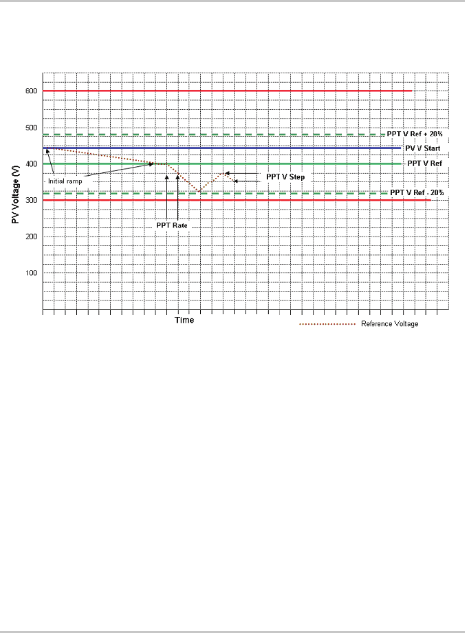
Figure 1-1 on page 1–4, user settable parameters include:
• PPT V Ref (ID# 37),
• I PPT Max (ID#42),
• PPT Enable (ID# 44),
• PPT Rate (ID# 45), and
• PPT V Step (ID# 46).
Upon entering the Power Tracking mode, it takes approximately 20 seconds for
the PV225S to ramp the PV voltage to the “PPT V Ref” setpoint regardless of the
actual PV voltage.
With the “PPT Enable” set to “0” (power tracker disabled), the PV225S will
regulate the DC Bus at the “PPT V Ref” setpoint. Regulating the DC bus means
drawing more or less current out of the PV array to maintain this desired voltage.
With the “PPT Enable” set to “1” (power tracker enabled), followed by the
expiration of the “PPT Rate” (MPPT decision frequency), the MPPT will reduce
the reference voltage by an amount equal to the “PPT V Step” value.
At this point the MPPT will compare the amount of AC output power produced to
the previous amount of AC power produced by the PV225S. If the output power
has increased, the next change made (after “PPT Rate” has again expired) to the
reference voltage, will be in the same direction.
Conversely, if the power comparison proves undesirable, the power tracker will
reverse the direction of the change to the “PPT_V Step”. The MPPT algorithm
within the PV225S will then continue this ongoing process of “stepping and
comparing” in order to seek the maximum power throughput from the PV array.
The changes made by the MPPT to the reference voltage are restricted to ± 20% of
“PPT V Ref” and by the maximum and minimum PV input voltage (600 and
300 volts respectively). Also, the MPPT will not attempt to produce power greater
than that allowed by the “I PPT Max” setpoint. If available PV power is above the
maximum allowable power level of the PV225S, the MPPT will increase voltage
as needed to maintain output power below rated maximum.
Introduction
1–4 152607
Optimization of the PV225S MPPT will result in an increase in energy production.
The user is encouraged to study the PV array’s I-V curves and to adjust the MPPT
user settable parameters accordingly.
Dynamic DC Minimum Operating Voltage
The PV225S employs a unique approach to the minimum DC input voltage for
operation. The CCU2 constantly monitors and calculates an average of the AC
utility input voltage, thereby adjusting the required minimum DC input voltage
threshold to optimize the sinusoidal AC output current waveform. Given a
nominal input voltage of 208 Vac, the minimum DC input voltage threshold is
300 Vdc. On a transient basis, the PV225S does have the ability to adjust the
minimum DC input voltage threshold to less than 300 Vdc.
Utility Voltage/Frequency Fault Automatic Reset
In the event of a utility voltage or frequency excursion outside of preset limits, the
PV225S will stop operation and display a fault at the operator interface. Once the
utility voltage has stabilized within acceptable limits for a period of at least
5 minutes, the PV225S will automatically clear the fault and resume normal
operation. Voltage and frequency fault setpoints are detailed later in this section.
Figure 1-1
Maximum Peak Power Tracking

Safety Features
152607 1–5
Safety Features
Anti-Island Protection
A condition referred to as "Islanding" occurs when a distributed generation source
(such as the PV225S Grid-tied Photovoltaic Inverter) continues to energize a
portion of the utility grid after the utility experiences an interruption in service.
This type of condition may compromise personnel safety, restoration of service,
and equipment reliability.
The PV225S employs a method for detecting the islanding condition using a
Phase-Shift-Loop (PSL). This method is implemented in the CCU2 to prevent
islanding of the PV225S. The CCU2 continuously makes minor adjustments to
the power factor phase angle above and below unity. In the event of a utility
interruption or outage, these adjustments destabilize the feedback between the
inverter and the remaining load, resulting in an over/under frequency or voltage
condition.
Upon detection of such a condition, the PV225S then performs an immediate
orderly shutdown and opens both the main AC and DC contactors. The fault
condition will remain latched until the utility voltage and frequency have returned
to normal for at least 5 minutes.
This method has been extensively tested and proven to exceed the requirements of
IEEE-929 (Recommended Practices for Utility Interface of Photovoltaic [PV]
Systems) and UL-1741 (Static Inverters and Converters for use in Independent
Power Systems).
PV Ground Fault Detection
The PV225S is equipped with a ground fault detection circuit by means of a
Hall-effect current transducer (CT8). This circuit is active when the PV array is
properly grounded. In the event of a ground fault exceeding 10 amps DC, the
PV225S will execute an immediate orderly shutdown, open both the main AC and
DC contactors, and report a ground fault on the LCD of the UFCU. The PV225S
will remain faulted until the ground fault is remedied and the advisory is cleared at
the operator interface.
For additional information, see Chapter 4, “Troubleshooting”.
DC Over-voltage Detection
In the event of DC voltage greater than 600 Vdc, the PV225S will execute an
orderly shutdown and will report a fault to the operator interface. If DC voltage
remains greater than 600 Vdc, the PV225S may be irreparably damaged.
See Chapter 4, “Troubleshooting” for further information on this fault condition.
Introduction
1–6 152607
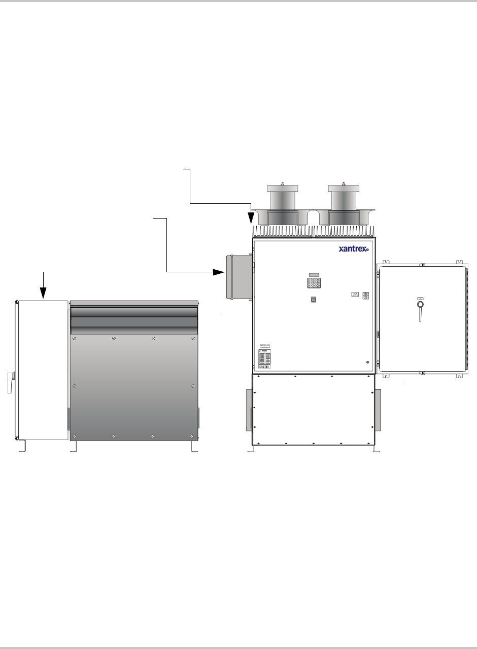
Physical Characteristics
The PV225S comes in two modules comprised of six enclosures to house the
electronics described above. The first module includes the Main Inverter
Enclosure, Inductor Enclosure, DC Interface Enclosure, and Communications
Enclosure. The second module includes the Transformer Enclosure and AC
Interface Enclosure.
These components are identified in Figure 1-2.
Figure 1-2
PV225S Major Components
Main Inverter
Enclosure DC Interface
Enclosure
Inductor
Enclosure
Transformer
Enclosure
AC Interface
Enclosure
Power Electronics
Communications
Enclosure

Physical Characteristics
152607 1–7
Main Inverter Enclosure
The PV225S Main Inverter Enclosure is NEMA-3R rated and contains the power
distribution panel, the converter control unit (CCU2), and the power electronics
matrices. Also found within the Main Inverter Enclosure are some of the system
protection devices (such as the sense and control power fuses).
Power Distribution Panel
This panel contains many of the Electromechanical, protective, and control power
components necessary to support the operation of the PV225S.
Converter Control Unit (CCU2)
The CCU2 is a Digital Signal Processor (DSP) based control board that performs
numerous control and diagnostic functions associated with PV225S operation. Its
most significant tasks are control of PV225S electromechanical components and
power electronics converters, signal conditioning for high voltage signal inputs
and communication with the Universal Front Panel Control Unit, and system
sensors. The CCU2 also contains the necessary DC power supplies to support its
operation.
Power Electronics Matrices
The power electronics converters are located at the top of the PV225S main
inverter enclosure. Both the left and right matrices are comprised of six switching
transistors (IGBTs), transistor gate drive electronics, a laminated power bus, DC
capacitor bank, and an aluminum extrusion heatsink with a cooling fan. The fans
are located above each matrix heatsink.
The PV array is tied logically to the matrices DC bus within the DC interface
enclosure. The embedded CCU2 control unit manages the transfer of power
between the DC bus and the utility grid by sending digitized gating signals to the
IGBTs for producing a high-fidelity, sinusoidal output.
Inductor Enclosure
The Inductor Enclosure is NEMA-3R rated. It contains the necessary filter
components to ensure the PV225S line current meets IEEE-519 (1992, Standard
Practices and Requirements for Harmonic Control in Electrical Power Systems)
and UL 1741 (2001, Static Inverters and Converters for use in Independent Power
Systems) harmonic distortion requirements. Mounted on both the right and left
side of the lower enclosure are inductor fans to allow cooling of the line filter
components within. This enclosure also serves as the mounting base for the
PV225S Main Enclosure.
Introduction
1–8 152607
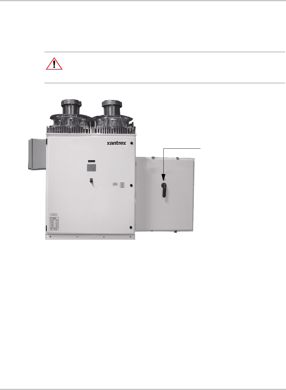
DC Interface Enclosure
The DC Interface Enclosure is NEMA-3R rated. The DC interface serves as the
connection interface between the PV array and the PV225S. This enclosure is
where the DC Disconnect Switch and DC contactor reside.
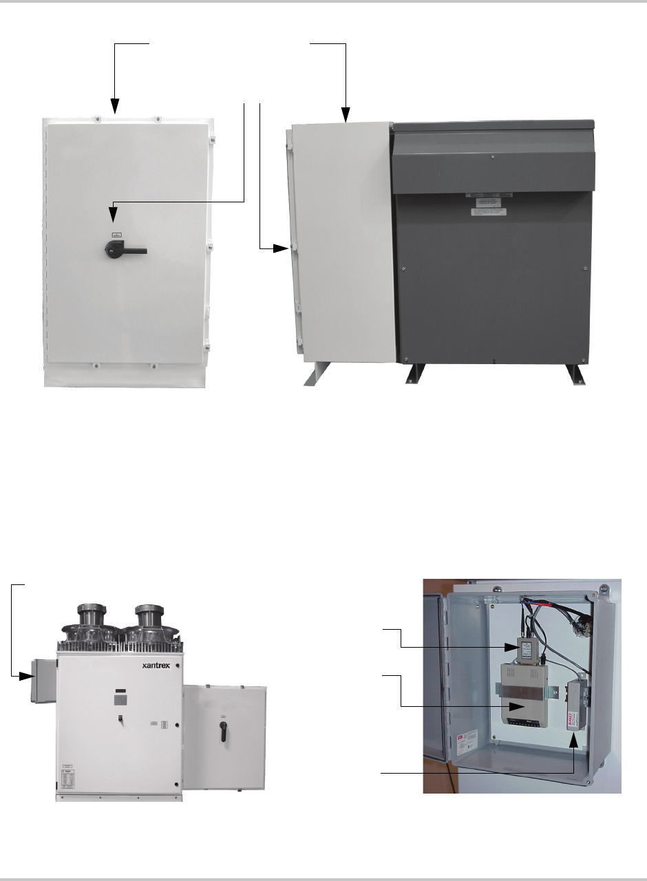
Transformer Enclosure
The Transformer Enclosure is NEMA-3R rated. The main isolation transformer
inside electrically isolates the PV225S from the utility power. Voltage-sensing
circuit wiring and soft-start circuit pass through the Transformer Enclosure from
the AC Interface Enclosure to the Main Inverter Enclosure.
AC Interface Enclosure
The AC Interface Enclosure is NEMA-3R rated. The AC interface serves as the
connection between the utility and the isolation transformer. This enclosure is
where the AC line fuses and AC Disconnect Switch reside. Also included in the
AC Interface Enclosure are the main AC contactor and transformer soft-start
circuit.
CAUTION: Equipment Damage
The fuses within the PV225S are intended for protecting the PV225S control circuitry
only. They are not intended to provide protection for the PV array or external cabling.
Figure 1-3
DC Interface Enclosure
DC Disconnect Switch
DC Interface Enclosure
Physical Characteristics
152607 1–9
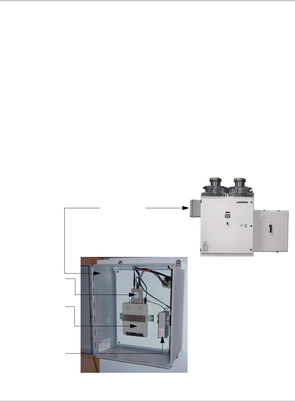
Communications Enclosure
The Communications Enclosure is NEMA-4 rated. It contains the hardware to
enable a personal computer to connect to the unit, either directly or remotely.
Hardware could include a POTS Connect Kit, a Wireless Connect Kit, or an
Ethernet LAN kit, or a Direct Connect Kit.
Figure 1-4
AC Interface Enclosure and Transformer Enclosure
AC Disconnect
Switch Transformer Enclosure
AC Interface Enclosure
Figure 1-5
PC Connections in the Communications Enclosure
Communications Enclosure
MultiTech 56K
Modem
RS232/FO
Converter
SA2 Surge
Arrestor
POTS connection hardware is shown
in this photo.
Introduction
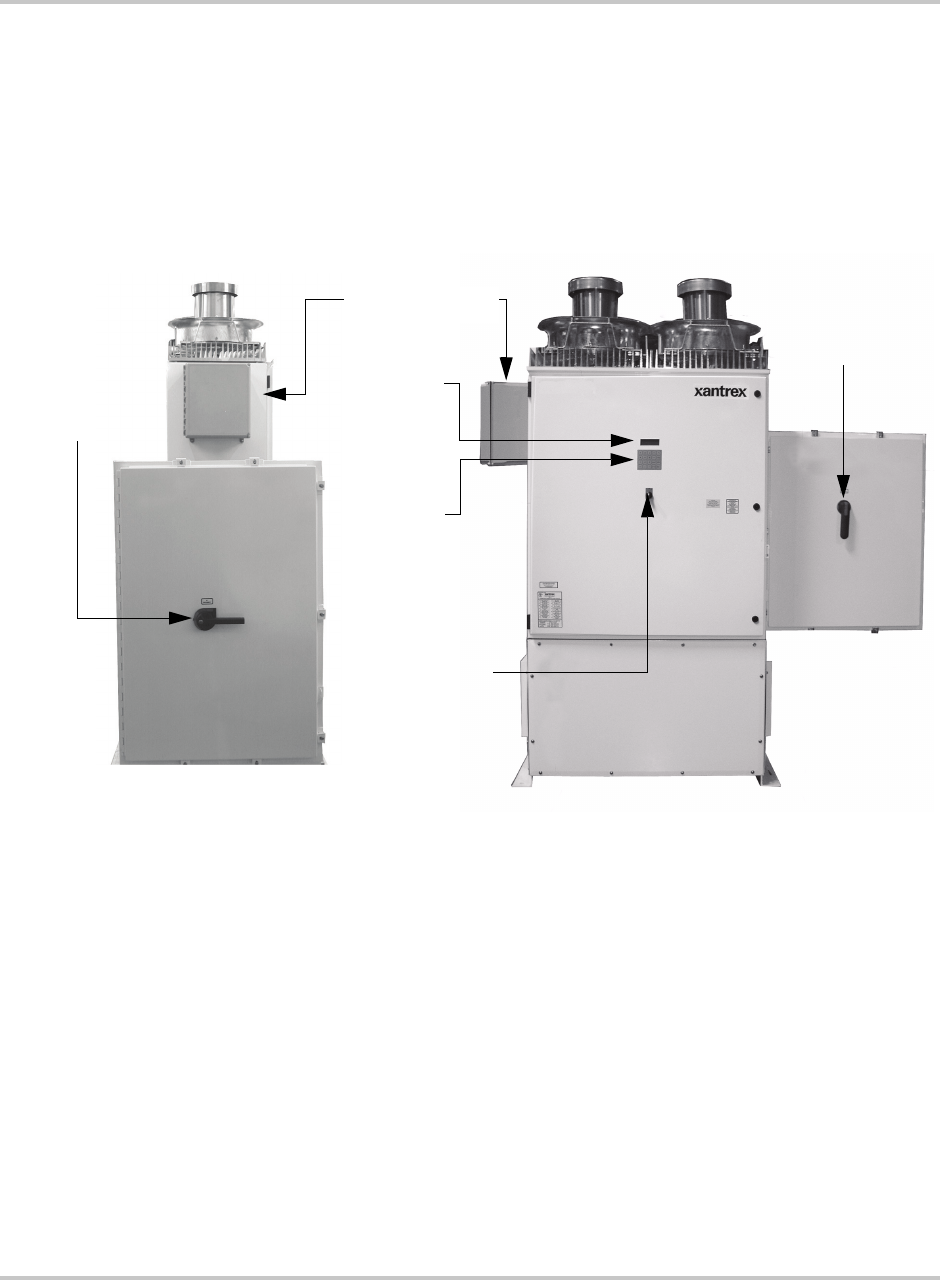
1–10 152607
Operator Interface Controls
Operator interface controls are located on the front door of the main inverter
enclosure. These controls include an ON/OFF Switch, 4-line LCD display and
keypad called the Universal Frontpanel Control Unit (UFCU). Additionally there
is an AC and DC Disconnect on the AC Interface Enclosure and the DC Interface
Enclosure Doors.
Main Enclosure Door Interlock Switch
The front door of the PV225S main enclosure is equipped with an interlock switch
to preclude operation while the front door is open. Opening the door of the main
inverter enclosure will initiate an immediate controlled shutdown of the PV225S
and opens both the main AC and DC contactors. The main AC and DC contactors
cannot be closed unless the door’s interlock is in the engaged position. The
PV225S is prevented from being restarted until the door is again closed and the
switch is in the engaged position.
It is required that the PV225S main enclosure door must be locked during normal
operation. The door interlock switch does NOT remove all hazardous voltages
from inside the inverter. Before attempting to service the PV225S, follow the
de-energize Lockout and Tag procedure on page 5–3.
Figure 1-6
PV225S Operator Interface Components
AC Disconnect
Switch
AC Interface Enclosure
(AC Side View)
DC
Disconnect
Switch
DC Interface
Enclosure
LCD
Display
Universal
Frontpanel
Control
(UFCP)
ON/OFF
Switch
Communication
Enclosure
Main Inverter Enclosure
(Front View)
Operator Interface Controls
152607 1–11
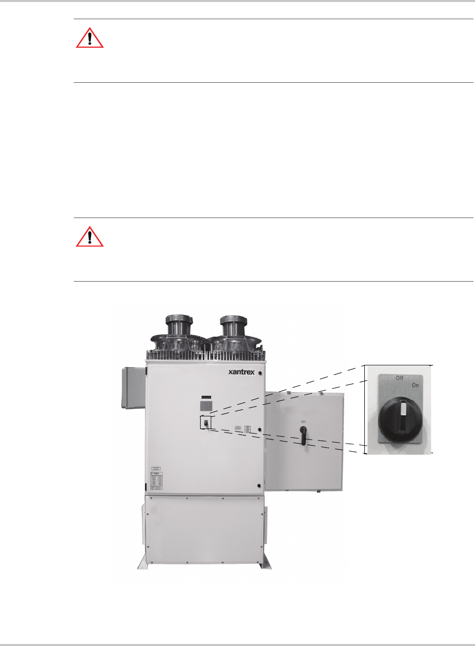
On/Off Switch
The PV225S incorporates a maintained position ON/OFF Switch (S3) located on
the front door of the main enclosure. Under normal conditions, the ON/OFF switch
is in the ON position. Turning the switch to the OFF position will initiate an
immediate controlled shutdown of the PV225S and open both the main AC and
DC contactors within the unit. The main AC and DC contactors cannot be closed
unless the switch is in the ON position. The PV225S is prevented from being
restarted until the ON/OFF switch is turned back to the ON position.
WARNING: Shock Hazard
Disengaging the main enclosure door interlock switch does NOT remove all hazardous
voltages from inside the inverter. Before attempting to service the PV225S, follow the
de-energize Lockout and Tag procedure on page 5–3.
WARNING: Shock Hazard
Turning the ON/OFF switch to the OFF position does NOT remove all hazardous voltages
from inside the inverter. Before attempting to service the PV225S, follow the de-energize
Lockout and Tag procedure on page 5–3.
Figure 1-7
O
N
/O
FF
Switch (S3)
Introduction
1–12 152607
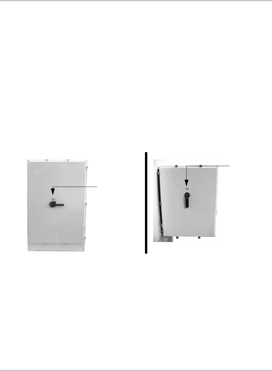
AC and DC Disconnect Switches
Both AC and DC interface enclosures are equipped with lockout hasps for
personnel safety. The enclosure doors should not be opened while the PV225S is
operating.
The switch handles and shafts provide a door interlock for both the AC and DC
interface enclosures. The doors cannot be opened when the switch is in the ON
position.
The DC Disconnect Switch (S2) is equipped with an auxiliary contact block
which enables the switch to be used as a load break DC disconnect. In the event
the DC Disconnect Switch is opened while the PV225S is processing power from
the PV array, the early-break contact block will signal the CCU2 (Converter
Control Unit 2) to stop processing power prior to opening the DC Disconnect
Switch.
Additionally, opening the DC Disconnect Switch will cause the PV225S to
execute an immediate orderly shutdown, open both the main AC and DC
contactors, and report a PV disconnect fault on the LCD of the UFCU.
Communication Features
The PV225S provides two types of information to the user:
• system status and/or fault information, and
• data logging information.
System status and fault information can be accessed using the Universal Front
Panel Control Unit (UFCU) or a personal computer (PC) using the Xantrex Solar
Graphic User Interface (GUI) software. Data logging requires the use of a PC
using the GUI software.
Figure 1-8
AC and DC Disconnect Switches
AC Disconnect
Switch (S1)
DC Disconnect
Switch (S2)
AC Interface Enclosure DC Interface Enclosure

Communication Features
152607 1–13
System Status and Fault Reporting
Basic system status and all fault conditions rising from within the PV225S are
reported to the UFCU. The unit stores the time and details of all faults in
non-volatile memory. The 4-line LCD will display a hexadecimal value and a
brief text description of the fault.
This information can also be accessed using a personal computer using the GUI
software either directly or remotely.
Types of status information include:
• Current Operating State or Goal State
• Fault Code (if applicable)
• Inverter State
• Line Voltage and Current
• Inverter Matrix Temperature
• Inverter Power
•PV State
• PV Voltage and Current
• PV Power
• Grid Frequency
• Peak Power Tracker Enabled
Data Logging
The inverter stores data values and software metrics for debugging. These values
are stored within the CCU2 controller board in non-volatile memory. Data logging
requires the use of a PC connection using the Xantrex Solar Graphic User
Interface (GUI) software.
The Data logging features include:
• Operational Values
• Internal Metrics
• Data Log Acquisition
• Graphic Data Analysis
• Fault Log Acquisition
• Accumulated Values
• Configurable Parameters
For details on using this feature, consult the GUI Help program.
Introduction
1–14 152607
Communication Methods
The PV225S communicates system status information to the user using the
following methods.
• The Front Panel Control Unit (UFCU) Display
• PC Connection (Direct or Remote) - Xantrex Solar Graphic User Interface
(GUI) Software required. Communication with a PC requires the selection of
one of the following options.
• Remote Connection -- This method has three options available. One of
these options will be field-installed prior to commissioning.
• POTS Connection
• Wireless Connection
• Ethernet LAN Connection
• Direct Connection -- This method is most commonly used by field
technicians for commissioning and troubleshooting purposes.
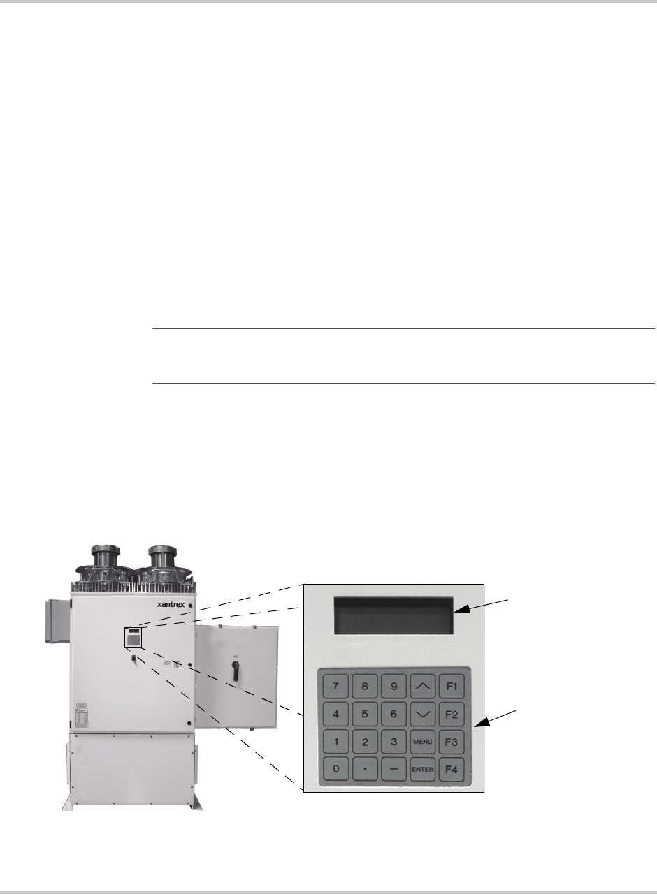
Universal Front Panel Control Unit (UFCU)
The UFCU keypad is located on the front of the Main Inverter Enclosure to
manipulate and view system operation and status.
The keypad is comprised of 20 touch-sensitive keys that provide a means to
navigate through the menus and alter user-changeable settings.
See “UFCU Keypad Operation and LCD Display” on page 2–6 for details.
Important:
The customer is responsible for providing the appropriate support service
to support a PC connection. (i.e., making arrangements for an analog phone line, data line,
wireless service or local area network.)
Figure 1-9
LCD Display and UFCU Location
LCD Display
Universal Front Panel
Control Unit (UFCU)
Communication Methods
152607 1–15
PC Connection Methods
Personal computers can be used to access the system status and programming
features of the PV225S. A computer can be connected either directly or remotely.
1. Remote Connect - uses one of the three kits below.
• POTS Kit - uses a MultiTech® 56K Modem, RS232/Fiber Optic
Converter (configured for ethernet) and SA2 Surge Arrestor.
• Wireless Kit - uses a GSM Wireless Modem.
• Ethernet LAN Kit - uses a data communication device to enable the unit
to connect to a local area network.
2. Direct Connect - This method is used for troubleshooting. It uses a
RS232/Fiber Optic Converter (configured for a PC), a DB25-to-DB25 gender
changer, and a DB25-to-DB9 Serial Cable.
Software is included to provide a graphic user interface that relates important
system information. This software is called Xantrex Solar Graphic Interface
(GUI). See “Minimum System Requirements” on page 2–26 for minimum system
requirements.
Figure 1-10
PC Connections in the Communications Enclosure
MultiTech®
56K
Modem
RS232/FO
Converter
SA2 Surge
Arrestor
Communications
Enclosure
POTS connection option shown.

Introduction
1–16 152607
POTS Access
Figure 1-11 illustrates the PV225S connected remotely to a personal computer.
Wireless Access
Figure 1-12 illustrates the PV225S connected remotely to a personal computer
using a wireless network.
Figure 1-11
POTS Access
Figure 1-12
Wireless Access
Communication Methods
152607 1–17
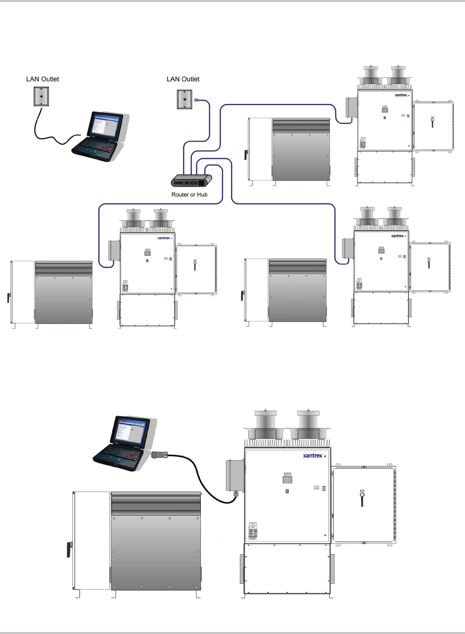
Ethernet LAN Access
The PV225S can be remotely accessed through a local area network.
Direct Access
Figure 1-14 illustrates the PV225S connected directly to a personal computer.
Figure 1-13
LAN Access
Figure 1-14
Direct Access

Introduction
1–18 152607
GUI Software Features
Read-only Menu The GUI software provides access to the following “Read-only Menu”
information. See Table 2-2, “Read Menu Descriptions” on page 2–11 for a
specific list of available parameters.
• Operational Values
• Internal Metrics
Write-Menu The GUI software provides control of the following system parameters. These
parameters are in the Write Menu.
• User-Configurable Parameters. See Table 2-5, “Write Menu Parameters” on
page 2–16 for a specific list of available parameters.
Data Logging The GUI software provides the following data collection/reports (data logging).
These features are not available through the Universal Front Panel Control Unit
(UFCU).
• Operational Values - The present operational values (such as PV voltage and
current, grid network voltage and frequency, or inverter current and power)
can be read remotely.
• Internal Metrics - The inverter also maintains internal software metrics for
remote review by Xantrex field service or engineering.
• Data Log Acquisition - The inverter maintains a data log in non-volatile
memory for up to 30 days, after which the oldest data is overwritten. The GUI
reads this data and updates a local file that can be imported to a spreadsheet.
• Graphic Data Analysis - Local data log files generated by the GUI can be
imported to a spreadsheet application, thus giving the ability to create a
graphical chart for display and analysis.
• Fault Log Acquisition - The inverter maintains a log of faults (description,
time and date). This can be viewed remotely. The fault log is stored in the
inverter’s non-volatile memory, and is also read by the GUI and stored at its
computer in a text file.
• Accumulated Values - The inverter tracks power production statistics, such as
total energy sold, operating hours, power production hours, peak power and
energy, energy by month, and energy by the hour. Accumulated values are
stored in the inverter’s non-volatile memory, and are also read by the GUI and
stored at its computer in a text file.
• Configurable Parameters - The configuration parameters controlling the
inverter’s operation can be viewed and changed from a remote GUI.
See Table 2-3 on page 2–14 for a list of the Data Logging parameters available.
2Operation
Chapter 2, “Operation” contains information on the basic operation of
the PV225S 225 kW Grid-Tied Photovoltaic Inverter.

Operation
2–2 152607
Description of System Operation
Overview
The PV225S is a fully automated grid-interactive photovoltaic inverter. System
startup, system shutdown, PV power tracking, and fault detection scenarios are all
governed and monitored by the CCU2 controller within the PV225S. Manual
interaction or control of the inverter is necessary only in the event of a system
fault. Additionally, the following conditions govern operation of the PV225S.
• Stable utility AC voltage and frequency as specified in Table A-3 must be
present for all states of operation.
• PV voltage as specified in Table A-3 must be present.
• With the exception of the Matrix Test state, the ON/OFF switch, located on the
front door of the PV225S main inverter enclosure, must be switched to the ON
position for all operating states.
• The door of the main inverter enclosure must be closed with the door
interlock switch in the engaged position.
• Both the AC and DC Disconnect switches must be in the ON or closed
position.
• Fault conditions must not be present.
Faults
Fault states are automatic from any state of operation. In the event of a fault
condition, the PV225S will immediately stop processing power and execute an
immediate orderly shutdown, open both the main AC and DC contactors, and
remain in a faulted state until the fault is remedied and cleared (manually or
automatically).
Most faults are latching, and only those faults associated with grid disturbances
are auto-clearing and thus enable the PV225S to restart after a 5 minute delay
period. All fault conditions arising from within the PV225S are reported to the
UFCU (Universal Frontpanel Control Unit). The 4-line LCD on the UFCU will
display a hexadecimal value (fault code) and a brief text description of the fault.
Once the cause of the fault has been identified and corrected, and it is determined
to be safe to proceed, PV225S faults may be cleared from the UFCU keypad or
via the remote GUI.
See “Clearing Faults Manually” on page 4–3 for instructions on this procedure.
Description of System Operation
152607 2–3
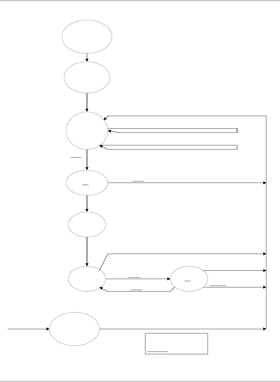
Figure 2-1
Operating States Flow Chart
INITIALIZING
PV contactor opened.
Inverter matrix off.
Grid contactor open.
Green LED on. Red off.
POWER UP
KEY
DISABLE
PV contactor open.
Inverter matrix off.
Grid contactor open.
System State: Key Disable
Inverter State: Standby
PV State: Sleep
SLEEP
for at least 10
seconds
System State: Shutdown
Inverter State: Standby
PV State: Sleep
PV Voltage >
300V
Close K2
PV Voltage <
50V
(
300V
-
250V
margin)
PV Contactor Closed
Inverter matrix off. Line contactor open
PV Contactor Open
WAKE UP
for 5.0 min.
(PV T START)
PV Voltage < 440V (PV V Start)
PV Voltage > 440V
(PV V START)
K1 Settle
for
.5
seconds
ON LINE
PV Power < 1.0kW (PV P STOP)
PV Power > 1.0kW (PV P STOP)
PV Voltage <
300V
(Min. Oper.)
TEST
for 5.0 min.
(PV T STOP)
PV Voltage <
300V
(Min. Oper.)
5 minutes elapsed
System State: Shutdown
Inverter State: Standby
PV State: Wake Up
System State: Shutdown
Inverter State: Main Settling
PV State: Wake Up
System State: Power Tracking
Inverter State: On Line
PV State: On Line
System State: Power Tracking
Inverter State: On Line
PV State: Sleep Test
Grid Contactor K1 Close
Inverter Matrix On
FAULT
PV contactor opened.
Inverter matrix off.
Grid contactor open.
Red LED on. Green off.
Fault from any State Fault Cleared
Retrun to Sleep State
Bold
- constant value
Italic - User settable.
Underline - Default value.
Enable Key
Return to Sleep State

Operation
2–4 152607
Operating States
A state machine implemented within the CCU2 control software governs the
operation of the PV225S with clearly defined transitions between its operating
states. There are five steady-state operating states and numerous intermediate
transition states.
• Power Tracking
• Transition
•Shutdown
• Fault
• Manual Current
• Matrix Test
• Automatic Sleep Test
Power Tracking
This is the standard operating state of the PV225S. The PV225S maximum power
tracker will demand maximum power from the PV array, given sufficient PV
irradiance.
The user should be aware of the following conditions governing PV225S state
transitions:
• Qualified utility voltage must be present for all states of operation.
• Fault states are automatic from any state of operation. A fault will cause the
PV225S to immediately stop processing all power. The fault condition will be
reported to the operator interface LCD.
• Most PV225S faults are latching and must be cleared at the operator interface
keypad before transitioning to another operating state.
• The ON/OFF switch, located on the front door of the PV225S, must be in the
ON position for all operating states except Matrix Test, in which case it must
be in the OFF position.
Transition
The intermediate transition states provide an orderly progression from one
operating state to the next. The user has the ability to manually transition the
PV225S between operating states via the operator interface keypad or remotely
using the GUI software. Manual transitions are initiated by entering a “Goal
State”, where the goal state is the desired operating state. Given all applicable
system parameters are within acceptable limits, and the request is valid within the
state machine, the PV225S will initiate the proper sequence of operations
necessary to progress to the requested goal state. Refer to Figure 2-1 on page 2–3
for an illustration of valid state transitions.

Operating States
152607 2–5
Shutdown
The line interface controller is idle. The CCU2 monitors the status of the PV array
and utility grid, waiting in standby until the PV array is available to produce
power to the grid.
Fault
The PV225S has encountered a fault condition. When this happens, regardless of
the PV225S state of operation, the PV225S will stop processing all power and
execute an orderly system shutdown. A description of the fault and fault code will
appear on the operator interface LCD. The Fault state may be cleared from the
keypad once the cause of the fault has been corrected. See Chapter 4,
“Troubleshooting” for a complete description of all fault codes.
Manual Current
This operating state is provided to evaluate the existing PV array V-I
characteristics. The PV controller regulates a constant amount of PV current as
commanded by the user from the operator interface keypad, up to the PV current
limit of the PV225S. If the user commands more PV current than is available, the
DC bus voltage will drop below the minimum bus voltage level and the PV225S
will enter Shutdown mode.
Matrix Test
This operating state is provided to verify proper operation of the matrices and
their associated control electronics. There is no power transfer between the PV
and utility in this mode. The ON/OFF switch must be in the OFF position for the
PV225S to enter this state.
Automatic Sleep Test
Toward the end of every solar day, the PV225S automatically determines when to
stop producing power dependent upon the output power of the inverter. As the net
output power of the PV225S nears zero, a timer is started to allow the inverter to
ride through any brief irradiance reductions.
Operation
2–6 152607
Operator Interface
The purpose of the operator interface is to provide a means of communicating
critical operational information to and from the unit. This communication occurs
between the operator and the UFCU Keypad and LCD display or between the
operator and a personal computer running the Xantrex Solar GUI software.
UFCU Keypad Operation and LCD Display
The UFCU keypad is located on the front of the Main Inverter Enclosure to
manipulate and view system operation and status.
The keypad is comprised of 20 touch-sensitive, peizio electric keys that provide a
means to navigate through the menus and alter user-changeable settings.
• Four function keys are available.
• F1 - While in the READ Menu, this key is used to clear faults.
In the WRITE Menu, it jumps to set “
Goal
:”.
• F2 - While in the READ Menu, this key jumps to display “
INV A Volts
”.
While in the WRITE Menu, this key jumps to display “
Max AC Volts %
”.
• F3 - While in the READ Menu, this key jumps to display “
PV Volts:
”.
While in the WRITE Menu, this key jumps to display “
Input #0:
”.
• F4 - While in the WRITE Menu, when commanding a goal state, this
function key confirms the change in goal state.
• Two Navigation keys are available.
•\/ or /\ moves forward or backward within the menu structure. Upon
reaching the end of the menu, it will roll-over to the beginning of the
same menu.
• Ten numeric keys (0 through 9), two symbol keys (“.” and “-”), and an
“ENTER” key are available for entering user-settable parameters.
• The “MENU” key allows you to enter the password-protected Write
parameters.
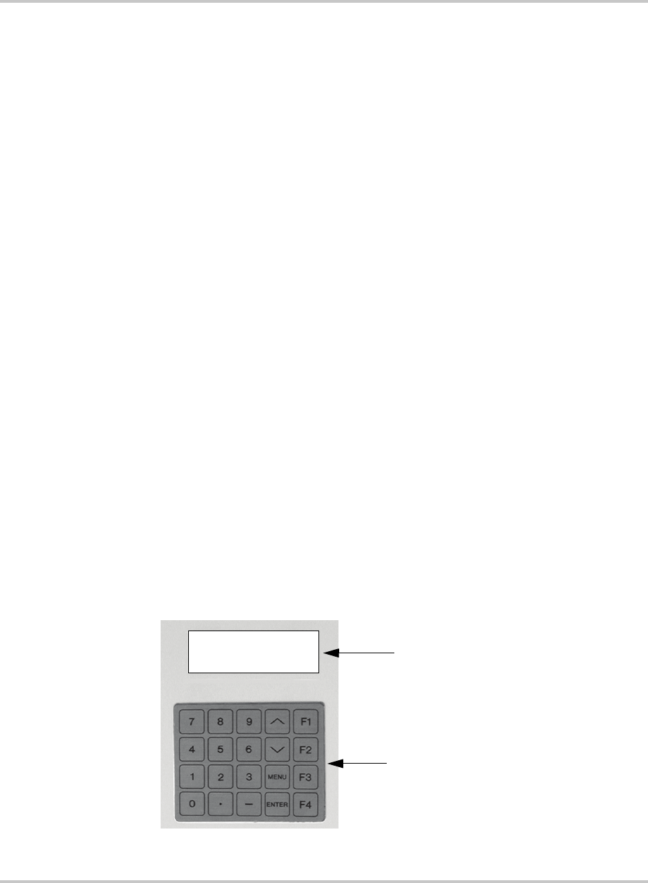
Figure 2-2
The Universal Front Panel Control Unit (UFCU) and LCD
LCD Display
UFCU Keypad
System: PWR Tracking
Inv: Online
Pv: Online
Goal : PWR Tracking
Standard Display
Operator Interface
152607 2–7
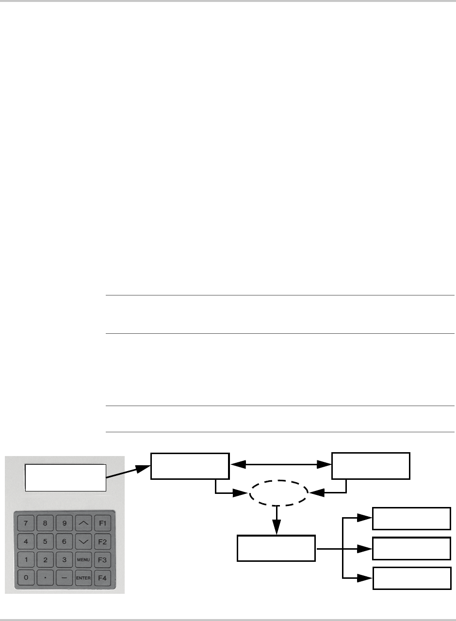
LCD Display - Initialization Screen
Any time AC power is applied to the unit, the LCD display will cycle through the
following displays while the system initializes. Once it’s done with this process,
the standard display will appear.
Standard Display
The Standard Display provides the following information:
• First Line - System Status (ID 1)
• Second Line - Inverter Status (ID 4)
• Third Line - PV Status (ID 13)
• Fourth Line - Goal State (ID 2)
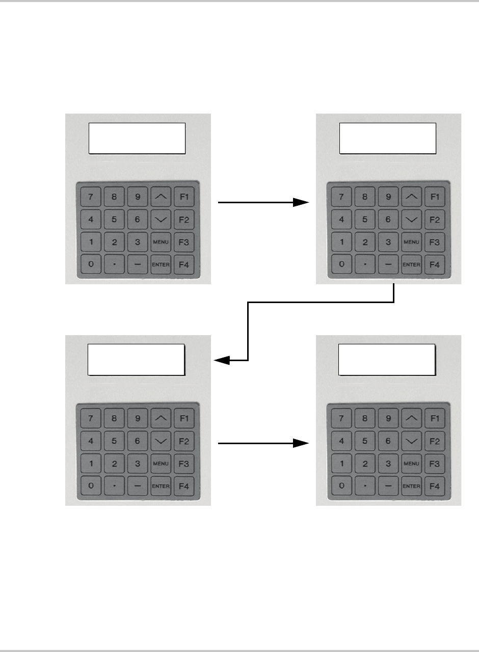
Figure 2-3
Initialization Screens
Initialising...
Front Panel v5.0
SW Build: 012805
Model: PV225S
XANTREX TECHNOLOGY
www.xantrex.com
(800) 670-0707
System: PWR Tracking
Inv: Online
Pv: Online
Goal : PWR Tracking
System: Initializing
Inv: Shutdown
Pv: Shutdown
Goal : Shutdown
Front Panel Initialization - Screen 1 Front Panel Initialization - Screen 2
System Initialization - Screen 3 Standard Display
Operation
2–8 152607
Menu Structure
The operator interface consists of three levels:
•READ Menu - operation information provided to the user from the PV225S.
The READ Menu consists of all operational values, the date and time. These
can be viewed any time the PV225S has control power.
•WRITE Menu - operational parameters provided to the PV225S from the user.
The WRITE Menu consists of a goal state sub-menu, and all system
configurable parameters. The WRITE Menu is password protected and may
only be changed by trained service technicians. In particular are parameters
relating to utility protection setpoints.
•Data Logging - the collection of specific parameters values over a period of
time. The data logging feature is only available if using the GUI. However,
the user does have the ability to view a snapshot of specific data using the
“Read by ID” feature. See Table 2-3 on page 2–14 and Table 2-4 on
page 2–14.
Information reported back to the user (READ Menu) occurs at the LCD above the
Universal Front Panel Control Unit (UFCU) and (if used) at the computer running
the GUI monitoring program. Making changes to the parameters within the WRITE
Menu is done with the UFCU keypad or the GUI software program and requires a
password.
Upon system power-up, the operator interface LCD will display the system
operating state on the first line. The inverter’s state of operation will be reported
on the second line. The PV Array’s state of operation will be reported on the third
line. The Goal target will be reported on the fourth line.
Important:
Specific grid-interface parameters within the WRITE Menu have been set in
the factory to the limits mandated by UL 1741. Any changes to these setpoints should be
agreed upon by the local utility and the equipment owner.
Important:
While in the WRITE Menu, the operator interface display will reset itself to
the standard display if there is no input for more than 2 minutes.
Figure 2-4
Operator Interface Menu Diagram
Enter Goal State
Set Date/Time
Change
Parameters
WRITE Menu
Password
Standard Display READ Menu
System: PWR Tracking
Inverter: Online
PV: Online
Goal: PWR Tracking

Operator Interface
152607 2–9
READ Menu
The READ Menu includes the following information:
• Current Operating State or Goal State
• Fault Code (if applicable)
• Inverter State
• Line Voltage and Current
• Inverter Matrix Temperature
• Inverter Power
•PV State
• PV Voltage and Current
• PV Power
• Grid Frequency
• Peak Power Tracker Enabled
Table 2-1 shows how the third and fourth line of the LCD will change as the
operator continues scrolling through the Menu. Table 2-2 on page 2–11 provides
a detailed description of READ Menu operational values that are displayed on the
LCD.
To Display Any Operational Value in the READ Menu
From the Standard Display, use the /\ or \/ keys on the operator interface keypad
to scroll through the READ Menu. The fourth line of the display will change to
display the appropriate information. See Table 2-1.
• The \/ key will scroll downward through the menu.
• The /\ key will scroll upward through the menu.
Upon reaching the end of the menu, it will go back to the beginning of the menu.
Table 2-1
Scrolling through the Read Menu Parameters
Read Menu Value Fourth Line of the LCD
Software Version (not shown) CCU Vx.xx FP V.x.x
Date/Time (not shown) Feb-14-2005 10:01:55
Read by ID# Value by ID#
Inverter A-B Volt INV A Volts:
Inverter B-C Volt INV B Volts:
Inverter C-A Volt INV C Volts:
Inverter A Current INV A Amps:
Inverter B Current INV B Amps:
Inverter C Current INV C Amps:
PV Voltage PV Volts:
PV Current PV Amps:
PV Power PV kW:
Grid Frequency Grid Freq:
PV PPT Enable PV PPT:
Ground Current Ground I:
Accumulated Power KWH:
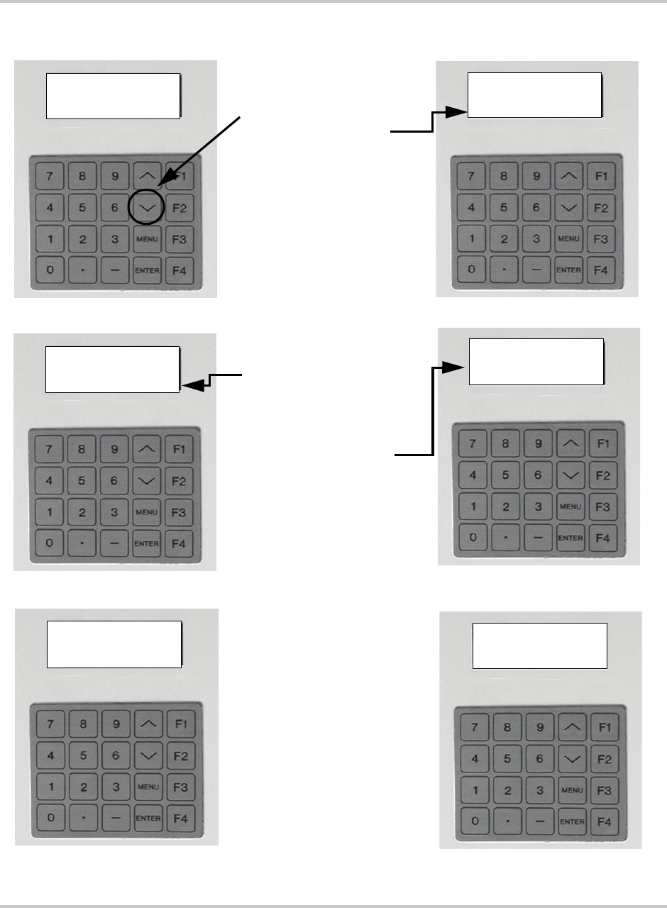
Operation
2–10 152607
Figure 2-5
Scrolling through the R
EAD
Menu
System: PWR Tracking
Inv: Online
Hit ENTER or "." "-"
Value by ID#
System: PWR Tracking
Inv: Online
Pv: Online
Goal : PWR Tracking
System: PWR Tracking
Inv: Online
Pv: Online
CCU Vx.xx FP Vx.x
System: PWR Tracking
Inv: Online
Pv: Online
Feb-14-2005 10:01:55
Standard Display
System: PWR Tracking
Inv: Online
Hit ENTER or "." "-"
Value by ID#
System: PWR Tracking
Inv: Online
PV: Online
INV A Volts: 480
From the Standard Display:
1. Press the \/ button once.
2. Fourth line displays
CCU version and Front
Panel version software.
3. Press the \/ button again.
4. Text on Fourth line displays
the Date and Time.
5. Press the \/ again.
6. Third and Fourth line
displays the “Read by ID”
feature.
7. Either enter a Read
parameter ID number to
jump to the specified
parameter or press the \/
again continue scrolling
through the Read Menu.
The fourth line will continue
to change as described in
Table 2-1.

Operator Interface
152607 2–11
Table 2-2
R
EAD
Menu Descriptions
Operational Parameter Description ID Units
Current Operating State
Displays as:
System: *
where * can be any one of the states
listed in the description for this
parameter.
Current system states include the following.
Initializing (0)
Key-disabled (1)
Shutdown (2)
Starting (3)
PWR Tracking (4)
Manual Current (5)
Matrix Test (6)
Faulted (7)
1N/A
System Goal State
Displays as:
Goal: *
where * can be any one of the states
listed in the description for this
parameter.
Goal States include the following.
Shut Down (0)
PWR Tracking (1)
Manual Current (2)
Matrix Test (3)
2N/A
Fault code See “Fault Code Descriptions” on page 4–4 for a detailed
list of Fault Codes.
3N/A
Inverter State
Displays as:
INV: *
where * can be any one of the states
listed in the description for this
parameter.
Inverter States includes the following.
Shut Down (0)
Stand-by (1)
Starting (2)
Main-Setting (3)
On-Line (4)
4N/A
Line A–B voltage
Displays as:
INV A volts: xxx
Line to line voltage 5 Vrms
Line B–C voltage
Displays as:
INV B volts: xxx
Line to line voltage 6 Vrms
Line C–A voltage
Displays as:
INV C volts: xxx
Line to line voltage 7 Vrms
Phase A current
Displays as:
INV A amps: xxx
Phase A current 8 Arm s
Phase B current
Displays as:
INV B amps: xxx
Phase B current 9 Arm s

Operation
2–12 152607
Phase C current
Displays as:
INV C amps: xxx
Phase C current 10 Arms
Inverter Real Power
Displays as:
INV KW:
Inverter Real Power 11 kW
Inverter Matrix Temperature
Displays as:
INV Temp:
Temperature of the Inverter IGBT matrix heatsink 12 °C
PV State
Displays as:
PV: *
where * can be any one of the states
listed in the description for this
parameter.
PV States include the following.
Shut Down (0)
Sleep (1)
Wakeup (2)
On-line (3)
Sleep-test (4)
13 N/A
PV Voltage
Displays as:
PV Volt: xxx
PV Voltage 14 Vdc
PV Current
Displays as:
PV amps: xxx
PV Current 15 Adc
PV Power
Displays as:
PV kW: xxx
PV Power 16 kW
Grid Frequency
Displays as:
Grid Freq:
Grid Frequency 17 Hz
Peak Power Tracker Enable
Displays as:
PV PPT: *
where * can be any one of the states
listed in the description for this
parameter.
Indication as to whether the PPT is enabled or disabled.
Off (0)
On (1)
18 N/A
Ground Current
Displays as:
Ground I:
Ground Current 19 N/A
kW Accumulated
Displays as:
kWH:
kW Accumulated 20 N/A
Table 2-2
R
EAD
Menu Descriptions
Operational Parameter Description ID Units
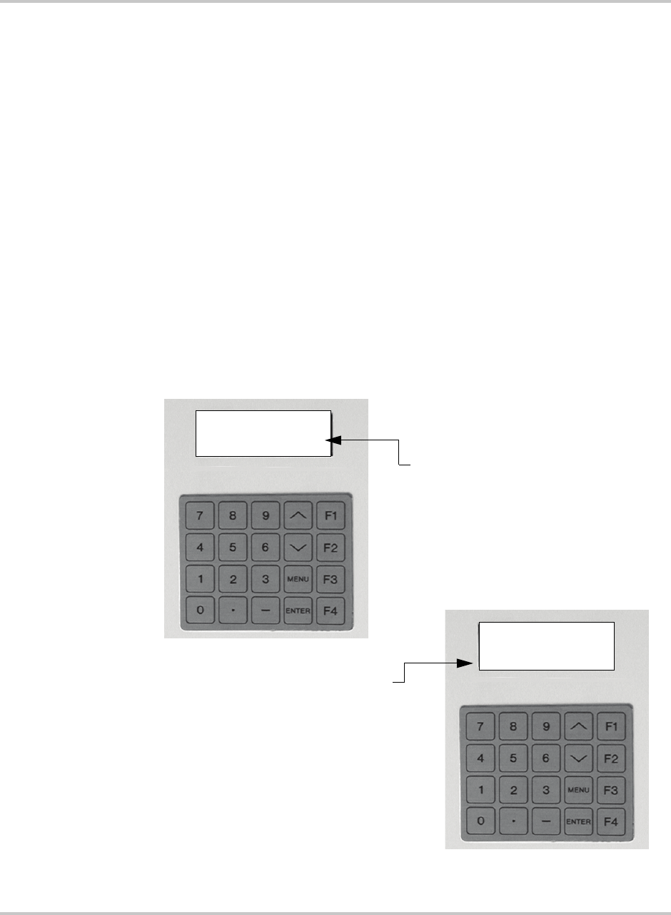
Operator Interface
152607 2–13
READ-by-ID
The Read-by-ID feature supports the ability of the user to view any Read or Write
parameter available within the menu structure. It also provides a means to view
data logging and accumulated values information. See Table 2-2 for a list of the
Read Menu parameters. See Table 2-3 for a list of data logging menu parameters.
See Table 2-4 for a list of accumulated values parameters.
To use the Read-by-ID Feature:
1. From the Standard Display, press the \/ key three times to scroll downward
through the menu to the Read-by-ID Menu item. Stop when the 3rd and 4th
line of the display change as shown in Figure 2-6.
2. Press <ENTER> to enter the Read-by-ID feature.
3. Use the keypad to enter the ID number of the Data Log Configuration or
Accumulated Value ID number and press <ENTER>. See Table 2-2 for a list of
READ Menu items and their ID numbers.
a) Press the “.” button to move upward in the Menu structure.
b) Press the “-” to move backward in the menu structure. These keys only
function in the Read-by-ID feature.
Figure 2-6
Read-by-ID Feature
System: Shutdown
Inv: Standby
Hit ENTER or "." "-"
Value by ID#
System: Shutdown
Inv: Standby
Hit ENTER or "." "-"
Read ID# xxx: xxx
Press <ENTER> when this
screen appears to access the
Read-by-ID feature.
Use the keypad to enter the desired
ID number and press <ENTER>.
The display will change as shown and will
show the requested value.
where:
xxx = any Menu ID
xxx = operational value of Menu ID
Use the “.” and “-” buttons to scroll backward
and forward within the Read-by-ID menu.

Operation
2–14 152607
Table 2-3 provides a list of the Data Logging Menu parameters.
Table 2-4 provides a list of the Accumulated Values Menu parameters.
Table 2-3
Data Logging Menu
ID# Usage
300 Data Log Daily Rate in Minutes
301 ID# of 1st parameter to be logged
302 ID# of 2nd parameter to be logged
303 ID# of 3rd parameter to be logged
304 through 390 ID#s of the 4th through the 90th parameter to be logged.
391 Not available
392 Data Log Nightly Rate in Minutes
393 First Daytime Hour
394 First Night-time Hour
395 Size of Data Log in Words
396 Words per record
397 Count of parameters per record
398 Offset from Data Log or next log record
299 Address of the Data Log
Table 2-4
Accumulated Values Menu
ID# Usage
600 Accumulated Operating Hours on actual day
601 Accumulated Operating Hours in actual week
602 Accumulated Operating Hours in actual month
603 Accumulated Operating Hours in actual year
604 Accumulated Operating Hours since Commissioning
605 Accumulated Sell Mode Hours on Actual Day
606 Accumulated Sell Mode Hours in actual week
607 Accumulated Sell Mode Hours in actual month
608 Accumulated Sell Mode Hours in actual year
609 Accumulated Sell Mode Hours since Commissioning
610-619 Not available
620 Accumulated Power Sold Hours on actual day
621 Accumulated Power Sold Hours in actual week
622 Accumulated Power Sold Hours in actual month
623 Accumulated Power Sold Hours in actual year
624 Accumulated Power Sold Hours since Commissioning
625 Accumulated Power Sold Hours since last reset
626-629 Not available
630 Peak Power monitored today

Operator Interface
152607 2–15
WRITE Menu
The WRITE Menu includes the following parameters:
• Ground Current Max
• PPT Voltage Reference
• PV Voltage Start
• PV Time (Start and Stop)
• PV Power Stop
• PPT Current Max %
• Manual Current %
• PPT Enable
• PPT Update Rate and Voltage Step
Table 2-5 provides a detailed description of WRITE parameters that are displayed
on the LCD.
631 Peak Power monitored this week
632 Peak Power monitored this month
633 Peak Power monitored this year
634 Peak Power monitored since Commissioning
635-639 Not available
640 Peak Power Sold for a day
641 Peak Power Sold for a week
642 Peak Power Sold for a month
643 Peak Power Sold for a year
Important:
Specific grid-interface parameters within the WRITE Menu have been set in
the factory to the limits mandated by UL 1741. Any changes to these setpoints should be
agreed upon by the local utility and the equipment owner.
Table 2-4
Accumulated Values Menu
ID# Usage
Important:
Write parameters require a password to access and should only be changed
by authorized personnel.

Operation
2–16 152607
Changing and Displaying WRITE Menu Parameter Values
Follow the procedure below to change WRITE Menu parameters.
To change WRITE Menu parameters:
1. From the standard display or anywhere in the READ Menu, you may access
the WRITE menu parameters by pressing the <MENU> key. This will ask for a
password.
2. Enter the password <5><9><4> and press the <ENTER> button.
a) If the wrong password is entered, the display will again prompt the user
for the password.
b) If a mistake is made while keying in the password, the /\ or \/ keys may be
used as a backspace key.
3. Once within the Write Menu, the first item is the “Set Goal State”. Use the /\
or \/ key on the operator interface keypad to scroll through the WRITE Menu
parameters.
a) To change the displayed parameter, press the <ENTER> button.
b) Enter the desired value and press <ENTER>. If the value entered is outside
the acceptable range for the parameter, the original value will remain.
c) To leave the WRITE Menu and return to the READ Menu, press the
<MENU> button once and the standard display will reappear on the LCD.
Table 2-5
Write Menu Parameters
Parameter Description ID Units
Default
Value
Maximum
Value
Minimum
Value
Set Goal State
Displays as:
Hit ENTER to set
Goal:
Commands a Goal State.
Set Date
Displays as:
042805
The date is entered
month-day-year (mmddyy):
April 28, 2005 is entered
042805
.
Set Time:
Displays as:
163000
The time is entered in military
hours-minutes-seconds
(i.e., 24-hour clock): 4:30 pm is
entered
163000
.
Maximum Grid
Voltage
Displays as:
Max AC Volts %:
This parameter sets the trigger
point value for “AC voltage High”
(0013) fault. If the grid voltage is
over this parameter’s value, the
fault is triggered. The upper limit
of this parameter is restricted by
UL requirements.
32 Percentage
of
Nominal
voltage
110 110 105

Operator Interface
152607 2–17
Minimum Grid
Voltage
Displays as:
Min AC Volts%:
This parameter sets the trigger
point value for “AC voltage low”
(0012) fault. If the grid voltage is
below this parameter’s value, the
fault is triggered. The lower limit
of this parameter is restricted by
UL requirements.
33 Percentage
of
Nominal
voltage
88 95 88
Maximum Grid
Frequency
Displays as:
Max AC Freq:
This parameter sets the trigger
point value for “AC frequency
high” (0011) fault. If the grid
frequency is over this parameter’s
value, the fault is triggered. The
upper limit of this parameter is
restricted by UL requirements.
34 Hertz 60.5 60.5 59.5
Minimum Grid
Frequency
Displays as:
Min AC Freq:
This parameter sets the trigger
point value for “AC frequency
low” (0010) fault. If the grid
frequency is below this
parameter’s value, the fault is
triggered. The lower limit of this
parameter is restricted by UL
requirements.
35 Hertz 59.5 59.5 60.5
Maximum Ground
Fault Current
Displays as:
Max Gnd Flt I
This parameter sets the trigger
point value for “Ground Over
Current” (0033) fault. Once the
current through the ground cable
is greater than the value of this
parameter, the fault is triggered.
36 Amps 10 20 1
Peak Power Tracker
Reference Voltage
Displays as:
PPT V Ref:
This is the initial PV voltage the
inverter is going to try to keep as it
goes into on line mode. If the
power tracker is off, the inverter
will draw current from the PV
array to maintain this reference
voltage. If the power tracker is on,
this is the reference voltage from
which the inverter start exploring
voltages that produce more power.
37 Volts 400 600 300
PV Wakeup Voltage
Displays as:
PV V Start:
This is the trigger point that
transitions the inverter from PV
Sleep state to PV Wake Up state.
When the PV voltage reaches the
value of this parameter the
inverter transitions into PV Wake
Up mode.
38 Volts 440 600 300
Table 2-5
Write Menu Parameters
Parameter Description ID Units
Default
Value
Maximum
Value
Minimum
Value

Operation
2–18 152607
Time Delay for PV
Wake up
Displays as:
PV T Start:
Time delay to transition from PV
wake up state to PV On-line state.
Once the inverter is in PV Wake
Up mode, it waits for the amount
of time determine by this
parameter before transitioning into
PV on-line mode. During this time
the inverter checks that the PV
voltage is no less than the PV
wake voltage, otherwise it goes
into PV Sleep mode.
39 Seconds 300 1200 0
Time delay for PV
Sleep Test
Displays as:
PV T Stop:
This is the amount of time the
inverter will be in Sleep Test mode
if the output power continues to be
below “PV P Stop”. The inverter
will exit Sleep Test mode towards
on-line mode if the power is over
“PV P Stop” or towards Shutdown
mode if the “PV T Stop” timer
expires.
40 Seconds 300 1200 0
PV Output Power to
Enter Sleep Test
Mode
Displays as:
PV P Stop:
This is the output power trigger
point for the inverter to transition
into sleep test mode. When the
output power is below the value of
this parameter the inverter enters
sleep test mode.
41 KW 1 10.0 0.1
Power Tracker
Maximum Output
Power
Displays as:
I PPT Max:
This parameter sets the percentage
of maximum rated power the
inverter will produce when in
power tracker mode. For example,
a 100 Kw system with this
parameter set to 50 will not
attempt to produce more than 50
Kw.
42 Percentage
of
maximum
output
power.
100 110 0
Manual Current
Output
Displays as:
I Manual:
This parameter sets the percentage
of maximum out current the
inverter will attempt to produce
while in manual current mode.
43 Percentage
of
maximum
output
current.
25 110 0
Table 2-5
Write Menu Parameters
Parameter Description ID Units
Default
Value
Maximum
Value
Minimum
Value

Operator Interface
152607 2–19
Enable Peak Power
Tracker
Displays as:
PPT Enable:
This parameter switches on and
off the Power Tracker function.
When the Power Tracker is on, the
inverter will regulate the bus
voltage to optimize output power.
When the Power Tracker is off, the
inverter will regulate the bus
voltage to maintain it at “PPT V
Ref” volts.
44 0 = Off
1 = On
11 0
Power Tracker Rate
Displays as:
PPT Rate:
This parameter sets the rate at
which the Power Tracker function
makes changes to the voltage
reference point as it tries to find
the optimal position. For example,
if the value of this parameter is
0.5, then every half a second the
power tracker will increase or
decrease the voltage reference
point to check if more power can
be produced at the new level.
45 Seconds 0.5 10.0 0.1
Power Tracker Step
Displays as:
PPT V Step:
This parameter sets the size of the
change the Power Tracker will
make to the voltage reference
point as it tries to find the optimal
position. For example, if the value
of this parameter is set to 1, the
Power Tracker will increase or
decrease the voltage reference
point by one volt at a speed of
“PPT Rate” to check if more
power can be produced at the new
level.
46 Volts 1 10.0 0.1
Table 2-5
Write Menu Parameters
Parameter Description ID Units
Default
Value
Maximum
Value
Minimum
Value
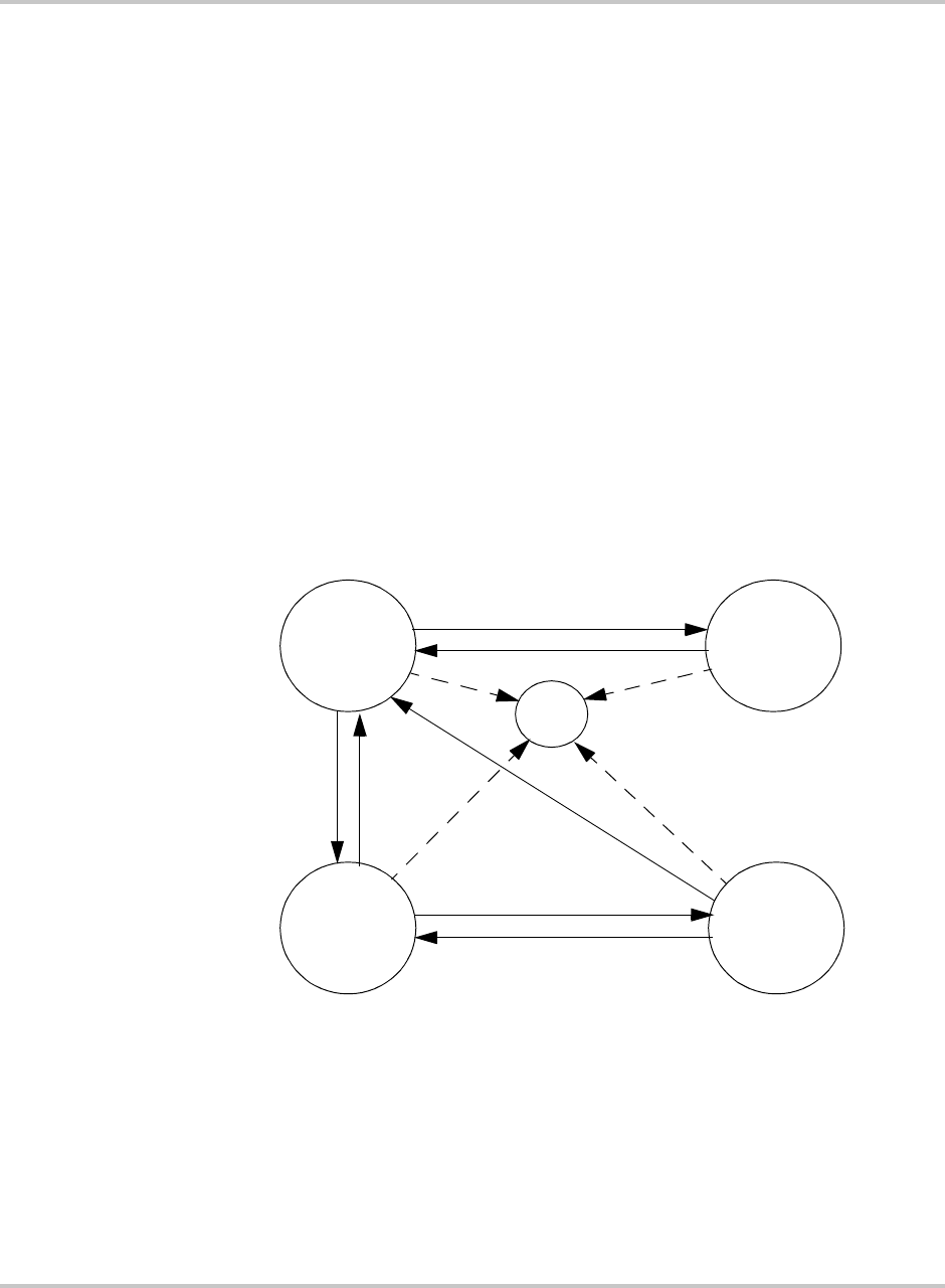
Operation
2–20 152607
Commanding Goal State Changes
To change the Goal State:
1. From the standard display press the <MENU> key. This will prompt the user for
a password. The LCD will change the third line of the display to “
Type and
Hit ENTER
” and fourth line of the display to “
Password:
”.
2. Enter the password <5><9><4> and press the <ENTER> button.
The LCD will change the third line of the display to “
Hit ENTER to set
”
and fourth lines of the display to “
Goal:
”.
3. Press <ENTER> again. The Goal State menu will show on the LCD display.
4. Scroll through the goal state menu with the /\ or \/ keys until the desired goal
state is displayed on the fourth line of the display.
5. Press <ENTER>. The LCD will then prompt the user by displaying the
following text on the third line: “
Press F4 to Confirm
”.
6. Press <F4> and the PV225S will transition to this goal state. If the goal state
requested violates the conditions of the state machine, the PV225S will
remain in the previous state of operation.
Figure 2-7
State Transition Diagram
SHUTDOWN
Inverter =
Disabled
POWER
TRACKING
Inverter =
PV Power
MATRIX
TEST
Inverter =
Idle
MANUAL
CURRENT
Inverter =
PV Current
FAULT
Automatic
Manual
Manual

Operator Interface
152607 2–21
Setting the Date and Time
Follow the procedure below to change the date and time.
To change the Date and Time:
1. From the standard display, press the <MENU> key. This will prompt the user
for the password. The LCD will change the third and fourth lines of the LCD
display as follows:
“
Type and
Hit ENTER
”
“
Password:
”.
2. Enter the password <5><9><4> and press the <ENTER> button.
3. Scroll down with the \/ key until date or time parameters are reached.
a) If you’re changing the date, the third and fourth lines of the LCD will
display as follows:
“
Type and hit ENTER
”
“
Set Date: MMDDYY
”
b) If you’re changing the time, the third and fourth lines of the LCD will
display as follows:
“
Type and hit ENTER
”
“
Set Time: HHMMSS
”
4. Press <ENTER>. Enter the proper date or time in a six digit format. For
example:
a) The date is entered month-day-year (mmddyy):
April 28, 2005 is entered
042805
<ENTER>.
b) The time is entered in military hours-minutes-seconds
(i.e., 24-hour clock): 4:30 pm is entered
163000
<ENTER>.
If a mistake is made while entering the date or time, the /\ and \/ keys may be
used as a backspace key. Any two-digit year “YY” may be entered for the
date, but regardless of the keyed entry, the maximum Month/Day “MMDD”
that the UFCU will accept is a “1231” or Dec. 31st. The maximum allowable
time entry the UFCU will accept is “235959”.
5. Once the entry is accepted, the third and fourth lines of the LCD display will
revert back to the following:
a) If you’re changing the date, the third and fourth lines of the LCD will
display as follows:
“
Hit ENTER to set
”
“
Set Date:
”
b) If you’re changing the time, the third and fourth lines of the LCD will
display as follows:
“
Hit ENTER to set
”
“
Set Time:
”
6. Pressing the <MENU> key will return the user to the standard display.

Operation
2–22 152607
Manual State Transitions
State conditions can also be transitioned manually. Refer to “Commanding Goal
State Changes” on page 2–20 for instructions on commanding PV225S goal states
for manual transitions.
Shutdown → Matrix Test → Shutdown
1. Turn the ON/OFF switch to the OFF position.
2. Command the PV225S to the Matrix Test.
3. After completing the Matrix Test, command the PV225S to Shutdown.
If the ON/OFF switch is turned to ON while the PV225S is in the Matrix Test state,
the PV225S will transition to Shutdown.
Power Tracking→ Manual Current→ Power Tracking or Shutdown
1. Verify the PV manual current parameter (
I Manual %
) is set to the desired
percent of rated.
2. Command the PV225S to Manual Current mode from the operator interface
keypad. While in the manual current mode, the user may change the PV
manual current parameter. However, the user may demand greater current
than the capacity of the PV array. If this causes the PV voltage to drop below
the minimum operating voltage (300 Vdc), the PV225S will transition to
Shutdown.
3. To exit the Manual Current mode, the user must manually command the
PV225S to Power Tracking.
Automatic State Transitions
State conditions can also be transitioned automatically. Refer to “Commanding
Goal State Changes” on page 2–20 for instructions on commanding PV225S goal
states.
Shutdown → Power Tracking → Shutdown
1. The ON/OFF switch must be turned to the ON position.
2. Once the PV voltage exceeds the PV voltage start set point (
PV V Start
) the
PV225S will start a wake-up timer (
PV T Start
).
a) If the PV voltage remains above the PV start voltage set point for the
duration of the wake-up timer, the PV225S will transition to Power
Tracking.
b) If the PV power drops below the PV power stop set point, (
PV P Stop
)
the PV225S will start a PV sleep timer (
PV T Stop
).
c) If the PV voltage and power remain below their respective setpoints for
the duration of the sleep timer, the PV225S will transition to Shutdown.
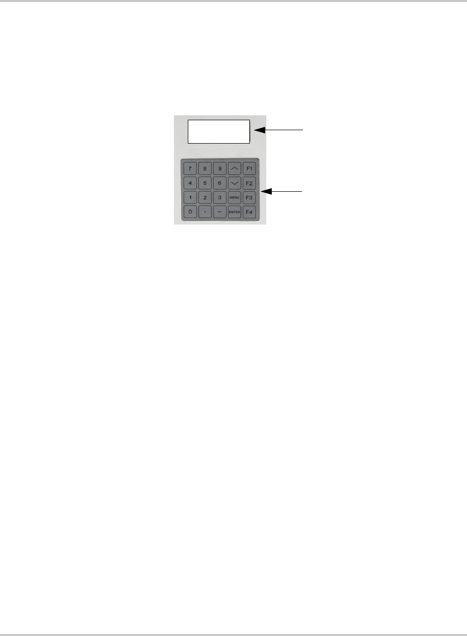
Auto-restart Feature
152607 2–23
Any State → Fault
If the PV225S encounters a fault, regardless of operating state, it will transition to
the Fault state. The PV225S will remain in this state until the fault condition has
been remedied and cleared. The Fault Code number will appear on the first line of
the LCD. A description of the fault will show on the second line. The third line of
the LCD will read “
F1 to Clear Fault?
”. The fourth line shows the goal state.
To clear the fault:
1. See Table 4-1, “Fault Codes” on page 4–4 for a complete listing of Fault
Codes and possible remedies. Correct the fault condition if possible and
attempt to clear the fault by pressing “F1”.
2. The ability to clear the fault can only be done from the READ Menu. If a fault
occurs while accessing the WRITE Menu, pressing <MENU> once will return
to the Read Menu, and “
F1 to Clear Fault
” will appear on the third line
of the LCD display.
Auto-restart Feature
In the event of a utility voltage or frequency excursion outside of those specified
in Table A-3 on page A–3, the PV225S will automatically transition to a Fault
condition. Once the Utility recovers for a period of five minutes, the PV225S will
automatically clear the fault, then resume normal operation.
Figure 2-8
LCD showing Fault Code
LCD Display showing
Fault Code
UFCU Keypad
Fault: 0070
INTERLOCK ACTIVATED
F1 to Clear Fault
Goal: PWR Tracking
Operation
2–24 152607
Energize Procedure (Startup)
To start up the PV225S:
1. Remove any lockout devices from the Utility connection circuit breaker and
PV disconnect switch.
2. Close the Utility connection circuit breaker.
3. Close the AC Disconnect Switch.
4. Close DC Disconnect Switch.
5. Turn the ON/OFF switch to the ON position.
After a 15 second initialization period, the PV225S will automatically transition
to ‘Waking Up’, given the PV voltage is greater than the PV V Start set point.
De-Energize/Isolation Procedure (Shutdown)
The following procedure should be followed to de-energize the PV225S for
maintenance:
To isolate the PV225S:
1. Turn the ON/OFF switch to the OFF position.
2. Open the DC Disconnect Switch.
3. Open the AC Disconnect Switch.
4. Open the utility connection circuit breaker.
5. Install lockout devices on the utility connection circuit breaker and DC
Disconnect Switch.
WARNING
The terminals of the DC input may be energized if the PV arrays are energized. In
addition, allow 5 minutes for all capacitors within the main enclosure to discharge after
disconnecting the PV225S from AC and DC sources.
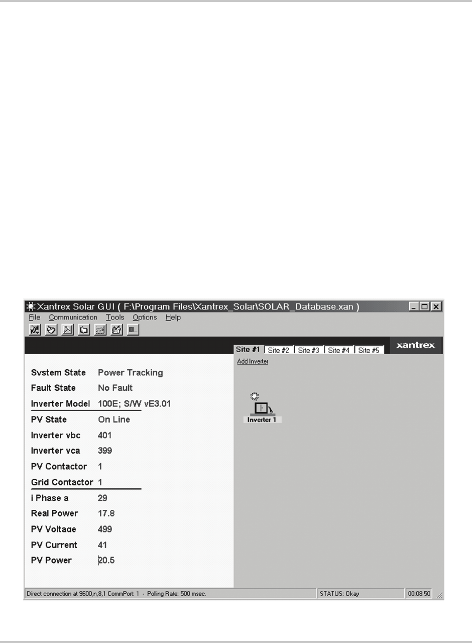
Computer Communications with the PV225S
152607 2–25
Computer Communications with the PV225S
The PV225S provides multiple options for communicating system status or data
logging through a personal computer using the Xantrex Solar Graphic User
Interface (GUI) software.
The Xantrex Solar Graphic User Interface (GUI) software is a Windows™-based
program that:
• displays system status,
• accesses inverter controls,
• accesses metering and data logging capabilities, and
• controls protective functions.
If multiple inverters are networked together, the software is capable of tracking up
to 50 inverters on the same network.
Determine which method will be used to communicate with the PV225S and
ensure the appropriate hardware is in place before proceeding with installing the
GUI. See the “PC Connection Methods” section of the PV225S 225 kW Grid-tied
Photovoltaic Inverter Planning and Installation Manual for instructions on
establishing the desired connection if this has not already been done.
Figure 2-9
GUI Interface Main Menu Screen

Operation
2–26 152607
Installing the Graphic User Interface (GUI) Software
The following section outlines the minimum system requirements for using the
GUI software and instructions for installing, configuring, and using the software.
Close all programs running on the computer before proceeding with the
installation.
Minimum System Requirements
The following lists the minimum requirements for using the Xantrex Solar
Graphic User Interface (GUI) Software.
• Personal Computer with a 486DC/66 MHz or higher processor; Pentium™ or
higher processor recommended.
• Microsoft Windows™ operating system (Win98 or later).
• 50 MB of free hard disk space.
• 64 MB of RAM (128 MB recommended)
• 56K modem (minimum)
• If using a LAN to access the inverters, a LAN card will be required in the PC.
Starting the Software Setup Program
Select one of the following methods to install the software:
• Use Autorun (must be enabled on your CDROM drive).
• Manual Start (assumes that Autorun is not enabled on your CDROM drive).
• Use a Command prompt to initiate the installation program.
Starting the Setup Program Using Autorun
To install the software with Autorun enabled on your CDROM drive:
1. Insert the CD into your computer’s CDROM drive. If autorun has not been
disabled for the CDROM in your computer, the Model Specific Software
Installation window shown in Figure 2-11 will appear.
Starting Setup Manually
To start the program from the CD if Autorun is disabled on your computer:
1. Insert the XANTREX SOLAR INVERTER GUI – INSTALLATION CD
into your CDROM drive.
2. Open Windows Explorer (or Click My Computer) and navigate to the
CDROM drive to view the contents of the disk.
3. Double-click on the file GUI_Menu.exe icon. The splash screen shown in
Figure 2-11 will appear.
4. Proceed to the Model Specific Software Installation section on page 2–28 to
continue with the installation.
Important:
Software levels shown in the following illustrations may not represent the
most current version.
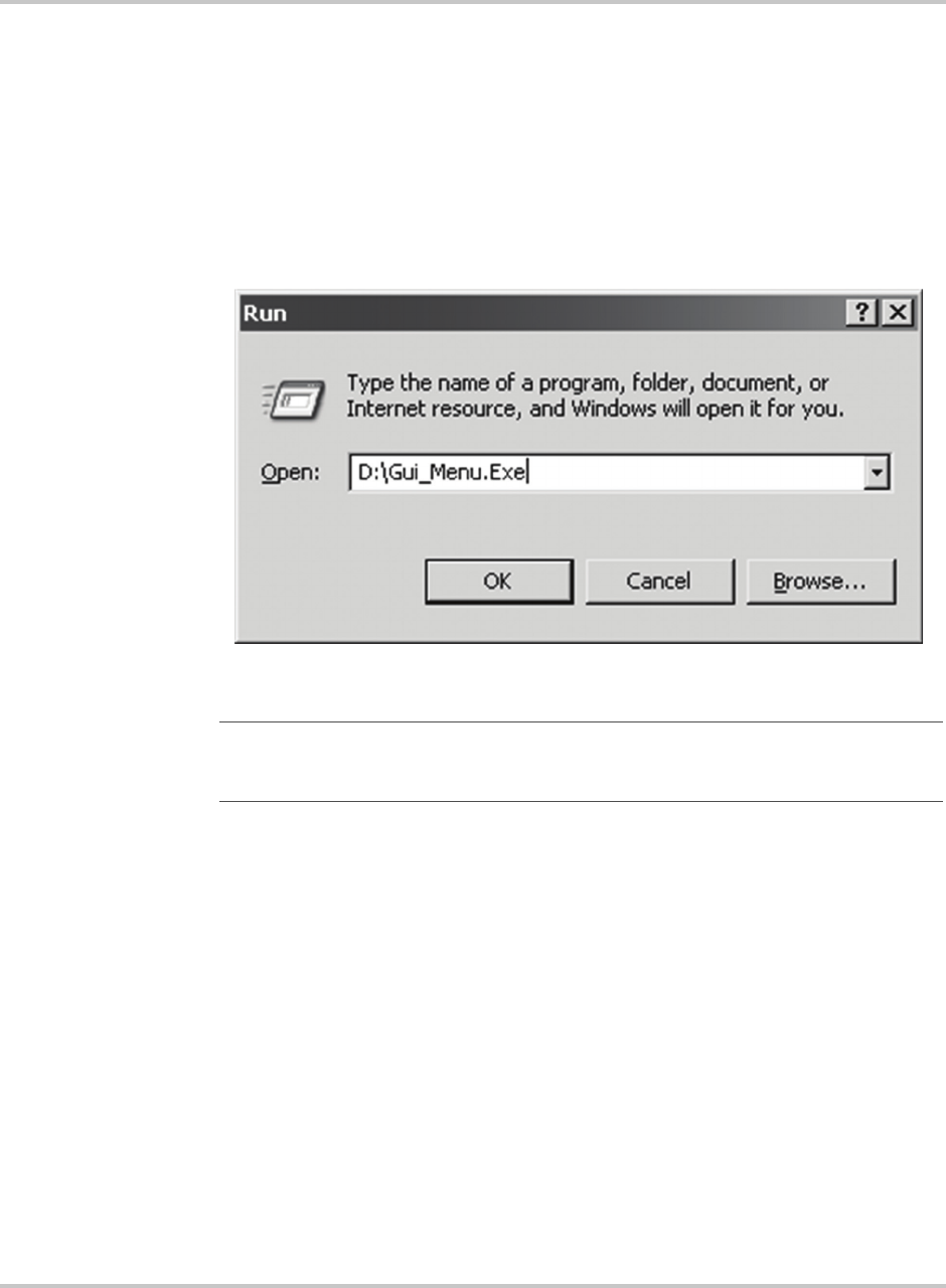
Computer Communications with the PV225S
152607 2–27
Starting Setup From a Command Prompt
To start the program from a command prompt:
1. Insert the XANTREX SOLAR INVERTER GUI – INSTALLATION CD
into your CDROM drive.
2. Click on START and select “RUN”.
3. Enter the drive letter assigned to your CDROM and the name of the
installation program as shown in Figure 2-10.
4. Click OK. The splash screen shown in Figure 2-11 will appear.
5. Proceed to the Model Specific Software Installation section on page 2–28 to
continue with the installation.
Figure 2-10
Staring Setup from a Command Prompt
Important:
The drive letter assigned to your CDROM may be different from the one
shown in Figure 2-10. Be sure to use the correct letter for your drive or the program will
not start.
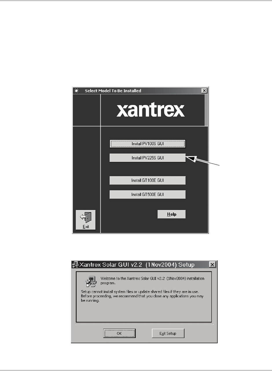
Operation
2–28 152607
Model Specific Software Installation
Once the Setup program has been started, installation of the GUI software can
continue.
To continue with the GUI software installation:
1. After the GUI Setup Splash Screen appears (Figure 2-11), click on the button
INSTALL PV225S GUI. The GUI Setup Welcome Window will appear next
(Figure 2-12).
Figure 2-11
GUI Splash Screen
Figure 2-12
GUI Setup Welcome Window
Click here to start
the model specific
installation
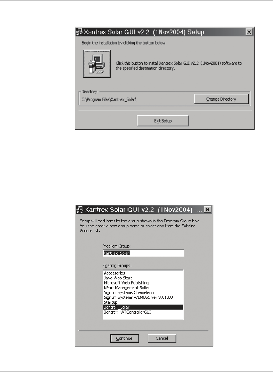
Computer Communications with the PV225S
152607 2–29
2. Click OK and the following window will appear:
If the directory provided in this window is acceptable for the installation,
proceed to Step 4. If not, click on the CHANGE DIRECTORY button and
provide a new name for the desired destination directory.
3. Click on the picture of the computer to continue with the installation.
The following window will appear:
Figure 2-13
GUI Setup Start Window
Figure 2-14
GUI Setup Program Group Window
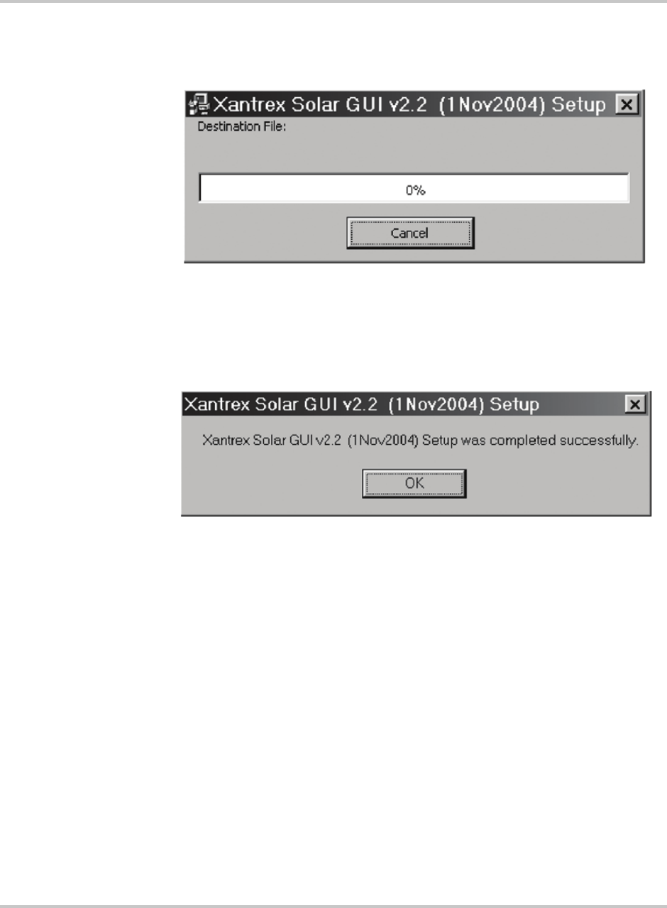
Operation
2–30 152607
4. Click CONTINUE to confirm the program group to be used.
The following setup progress indication window will appear.
5. When completed, you will see this:
6. Click OK. The GUI is now installed on the computer.
Figure 2-15
GUI Setup Progress Indicator Window
Figure 2-16
GUI Setup Start Window
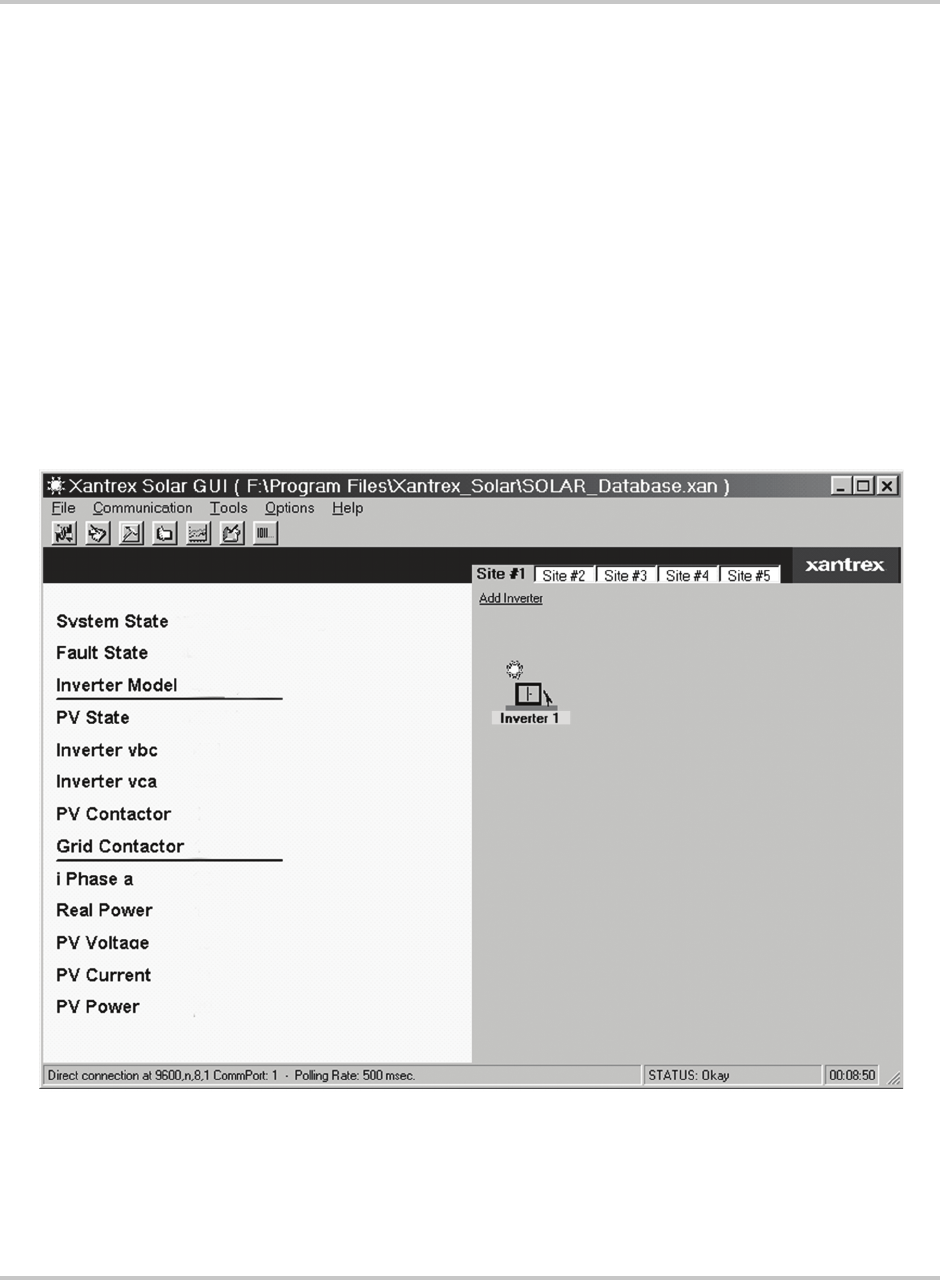
Computer Communications with the PV225S
152607 2–31
Running the GUI
To run the GUI software program, log onto the computer and click the following
menu items in the order shown below.
1. Window’s START button
2. PROGRAMS
3. XANTREX_SOLAR
4. XANTREX SOLAR GUI
Remote/LAN Connection
If no inverter is connected to the COM1 serial port of the computer, the following
screen will appear:
Figure 2-17
GUI Interface Screen if Connected Remotely
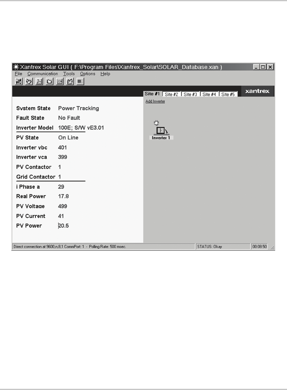
Operation
2–32 152607
Direct Connection
If the serial communication port of the inverter is connected to the COM1 serial
port of the computer, the following screen will appear.
Figure 2-18
GUI Interface Screen if Connected Directly
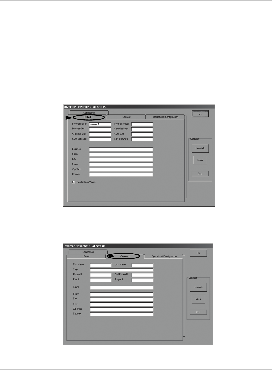
Computer Communications with the PV225S
152607 2–33
GUI Configuration - Adding Inverters
Once the GUI has started, you will need to configure each Inverter icon to reflect
the appropriate operational parameters for each inverter that is connected to the
system. The software automatically defaults to one inverter. To program that
inverter accordingly, follow the directions provided below.
To configure the inverters in the GUI:
1. With the GUI Main Menu open, Right-click on the “Inverter 1” icon.
2. Click on the tabs to display each page and fill out the required information.
3. Fill out the Detail Information in the form shown in Figure 2-19.
4. Fill out the Contact Information in the form shown in Figure 2-20.
Figure 2-19
Detail Screen
Fill out all the required
information on this
form.
Form Tab
Figure 2-20
Contact Screen
Fill out all the required
information on this
form.
Form Tab
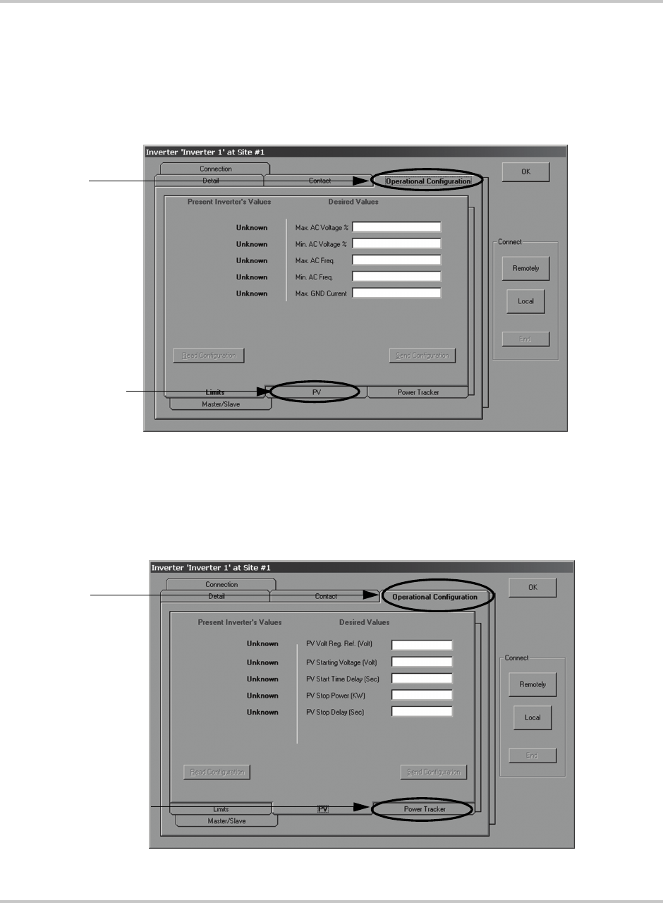
Operation
2–34 152607
5. Fill out the Operational Configurations Information in the form shown in
Figure 2-21 through Figure 2-23. This section has four sub-menu pages to
cover the following parameters.
a) Fill out Operational Limits Information requested.
b) Click on the PV Sub-menu to continue.
c) Fill out PV Information requested.
d) Click on the Power Tracker Sub-menu to continue.
Figure 2-21
Operational Configuration Screen - Limits
Fill out all the required
information on this
form.
Form Tab
Sub-menu
Figure 2-22
Operational Configuration Screen - PV
Fill out all the required
information on this
form.
Form Tab
Sub-menu
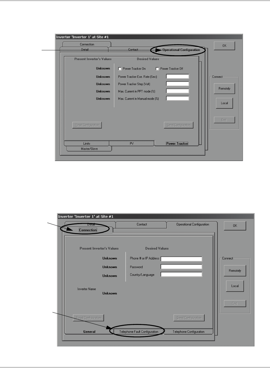
Computer Communications with the PV225S
152607 2–35
e) Fill out the Power Tracking Information requested.
f) Click on the Connections Form Tab to continue.
6. Fill out the Connection - General Information in the form in Figure 2-24.
7. Click on the Telephone Fault Configuration sub-menu to continue.
Figure 2-23
Operational Configuration Screen - Power Tracker
Fill out all the required
information on this
form.
Form Tab
Figure 2-24
Connection Configuration Screen - General
Form Tab
Fill out all the
required
information
on this form.
Sub-menus
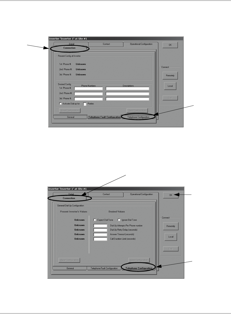
Operation
2–36 152607
8. Fill out the Connection - Telephone Fault Configuration Information in the
form shown in Figure 2-25.
9. Click on the Telephone Configuration sub-menu to continue.
10. Fill out the Connection - Telephone Configuration Information in the form
shown in Figure 2-26.
11. Once the information is complete, click the OK button to accept the changes
and return to the GUI main menu.
Figure 2-25
Connection Configuration Screen - Telephone Fault Configuration
Form Tab
Fill out all the
required
information
on this form.
Sub-menus
Figure 2-26
Connection Configuration Screen - General
Form Tab
Fill out all the required
information on this
form.
Sub-menus
Click on the OK
button to save the
changes and
return to the GUI
Main Menu.
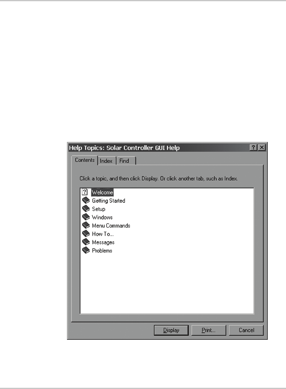
Computer Communications with the PV225S
152607 2–37
GUI Help
The GUI software program has a built-in help program. Once the program is
started, click on the HELP menu item to start the Help program.
The Help interface is divided into the following sections.
• Getting Started - IMPORTANT: Read this first
• Setup - Tutorial for setting up the GUI and configuring an inverter
• Windows - Description of each window of the GUI
• Menu Commands - Description of each GUI Menu command
• How to... - How to perform various tasks, by topic
• Reference - Glossary and miscellaneous information
• Messages - Explanation of GUI popup messages
• Problems - Troubleshooting for problems
Figure 2-27
GUI Interface Screen if Connected Directly
2–38

Computer Communications with the PV225S
152607 2–39

Operation
2–40 152607
3Commissioning
Chapter 3, “Commissioning” contains information on safely
commissioning the PV225S 225 kW Grid-Tied Photovoltaic Inverter.

Commissioning
3–2 152607
Commissioning Procedure
This section provides the procedure necessary to safely and correctly commission
a PV225S inverter.
Summary To commission the PV225S:
1. Ensure the Verification Tests have been completed and have passed
successfully. See the PV225S 225 kW Grid-tied Photovoltaic Inverter
Planning and Installation Manual, Section 4.
2. Begin the PV225S Commissioning Procedure as described in detail further in
this section. The steps are summarized below.
a) Start the GUI and open the PV225S Commissioning Procedure file.
b) Record the Serial Number.
c) Verify AC and DC Voltages.
d) Inspect Lower Inductor Enclosure.
e) Apply Grid Voltage.
f) Check the Front Panel Display.
g) Establish communications with the GUI.
h) Confirm Operational Parameters (AC, DC and Power Tracker).
i) Verify Door Interlock Functions.
j) Perform the Matrix Test.
k) Operate Inverter.
3. Submit the Test report and warranty form to Xantrex See “PRODUCT
REGISTRATION” on page WA–3.
Starting the Commissioning Test File
1. Start the Xantrex Solar Graphical User Interface (GUI) program.
a) Once the application has started, select “GENERAL PROCEDURES” from the
“TOOLS” pull-down menu.
b) In the “SELECT FILES” dialog box, choose “PV225S COMMISSIONING TEST”
and click the OPEN button.
2. Verify that both the AC (S1) and DC (S2) Disconnect switches are open.
3. Verify the ON/OFF switch (S3) is in the OFF position.
4. Once you finish these tasks, go back to the GUI and click on the check box to
indicate the task is complete. Go to the next step by clicking on the "NEXT"
button.
Important:
It is important to record any issues encountered while following this
procedure.

Starting the Commissioning Test File
152607 3–3
Serial Number
1. Enter the information required by GUI in the white text boxes on the form that
appears next. The converter serial number is located on a label placed on the
lower-left front of the Main Inverter Enclosure door.
2. Once you finish recording the required information, click on the check box to
indicate the task is complete. Go to the next step by clicking on the "NEXT"
button.
Verify AC Voltage
1. Open the door of the AC Interface Enclosure and verify that the Grid AC
cables have been installed at S1-2T1, S1-4T2, S1-6T3, TB11, and TB12.
2. With a voltmeter, verify if AC Grid voltage is present at the bottom of S1-
2T1, S1-4T2, S1-6T3. These fuses are located in the AC Interface Enclosure.
a) If voltage is correct, verify phasing using a phase rotation meter. The
phase rotation should be clockwise “A, B, C”.
b) If the voltage is not present, contact the installer, site electrician or site
operator to supply grid voltage to the unit.
3. If grid voltage is not available to the unit, open the AC Disconnect Switch
(S1) and lock the AC Interface Enclosure. The Commissioning Test procedure
must cease at this point. Do not attempt to continue the test until each step can
be checked and verified.
a) If grid voltage is not available and the Commissioning Test must be
stopped, SAVE the Commissioning File. This file will be used once grid
voltage has been applied and verified.
4. Once you finish verifying AC voltages, go back to the GUI Commissioning
Procedure and click on the check box to indicate the task is complete. Go to
the next step by clicking on the "NEXT" button.
Verify DC Voltage
1. Open up the DC Interface Enclosure and verify that the PV DC cables have
been installed correctly.
2. With a voltmeter, verify if PV DC voltage is present at S2-6 and K2-6T3.
3. Verify the correct polarity.
4. If the voltage is not present, contact the installer, site electrician or site
operator to supply PV voltage to the unit.
5. If PV DC voltage is not available to the unit, open the DC Disconnect Switch
(S2) and lock the DC Interface Enclosure. The Commissioning Test procedure
must cease at this point. Do not attempt to continue the test until each step can
be checked and verified.
a) If PV voltage is not available and the Commissioning Test must be
stopped, SAVE the Commissioning File. This file will be used once PV
DC voltage has been applied and verified.

Commissioning
3–4 152607
6. Once you finish verifying PV DC voltages, go back to the GUI
Commissioning Procedure and click on the check box to indicate that the task
is complete. Go to the next step by clicking on the "NEXT" button.
Inspect Inductor Enclosure
1. Remove the back and side access panels to the Inductor Enclosure and inspect
the connections.
2. Check for loose cables, rubbing, or interference.
3. Check the AC Sense Harness to make sure it is terminated and secured
properly and not touching either inductor L3 or L4.
4. Correct and record any defects.
5. Reinstall the Inductor Enclosure access panels removed above.
6. Once you finish inspecting the Inductor Enclosure, go back to the GUI
Commissioning Procedure and click on the check box to indicate the task is
complete. Go to the next step by clicking on the "NEXT" button.
Apply Grid Voltage
1. Verify all enclosure doors are closed and locked.
2. Close the AC Disconnect Switch (S1). This will energize the control power
circuits.
3. Look, listen and smell for signs of defects.
4. Record any defects found.
5. Once you finish applying the grid voltage, go back to the GUI Commissioning
Procedure and click on the check box to indicate the task is complete. Go to
the next step by clicking on the "NEXT" button.
Front Panel Display
1. Open then close the AC Disconnect Switch (S1) and look at the Front Panel. It
should show the Software Versions of the CCU and Front Panel. Record these
numbers. Then it should go into Initialization.
2. After about 20 seconds it will be in its “ready” mode. At this time the Fault
Code “0071 PV SWITCH OPEN” will be reported. Close the PV Disconnect
Switch (S2) and verify alarm 0071 clears by pressing the “F1” key on the
keypad of the UFCU. If additional alarms are present, refer to Table 4-1 on
page 4–4.
3. Once all faults are clear, the front panel should report Key Disable (“Switched
Off”) and show Inverter Status.
4. Using the \/ key, scroll down in the READ Menu and verify that the Time and
Date are correct.
5. If not, refer to the “Setting the Date and Time” on page 2–21.
6. Scroll thru the parameters and verify that they are present.

Starting the Commissioning Test File
152607 3–5
7. Once you finish checking the Front Panel Display, go back to the GUI
Commissioning procedure and click on the check box to indicate the task is
complete. Go to the next step by clicking on the "NEXT" button.
Establish Communications with the GUI
1. Verify that the appropriate hardware has been installed for the desired
communications connection–Remote or Direct Connect.
If not, refer to the “PC Connection Methods” section of the PV225S 225 kW
Grid-tied Photovoltaic Inverter Planning and Installation Manual for
instructions.
2. Verify that the communications with the inverter is working and that you have
established a connection with the inverter through the GUI.
a) Verify the signal lights on the data communication devices show activity.
Once communications are established, close the connection.
b) While at the Inverter, create a fault. This could be done by opening the
DC Disconnect Switch (S2).
c) Verify the Inverter calls the End User and reports the fault. The fault
reporting from the inverter to the End User will take approximately 1
minute.
d) Repair the fault–close the DC Disconnect Switch (S2)–and have the End
User clear the alarm.
If communications is not working as expected, refer to the “General
Troubleshooting” on page 4–2 for help.
3. Once you verify that communication has been established and is working
properly, go back to the GUI Commissioning Procedure and click on the
check box to indicate the task is complete. Go to the next step by clicking on
the "NEXT" button.
Confirm AC Operational Parameters
1. Verify the inverter’s AC limits.
2. Make any necessary changes.
3. Record these values.
4. Once you finish these tasks, go back to the GUI Commissioning Procedure
and click on the check box to indicate the task is complete. Go to the next step
by clicking on the "NEXT" button.

Commissioning
3–6 152607
Confirm DC Operational Parameters
1. Verify the Inverters PV Settings.
2. Make any necessary changes.
3. Record these values.
4. Once you finish these tasks, go back to the GUI Commissioning Procedure
and click on the check box to indicate the task is complete. Go to the next step
by clicking on the "NEXT" button.
Confirm Power Tracker Configuration Operational Parameters
1. Verify the inverter’s Power Tracker Configuration.
2. Make any necessary changes.
3. Record these values.
4. Once you finish these tasks, go back to the GUI Commissioning Procedure
and click on the check box to indicate the task is complete. Go to the next step
by clicking on the "NEXT" button.
Verify Door Interlock Functions
1. Open the front door of the Main Inverter Enclosure and verify a door interlock
fault is triggered (0070 “INTERLOCK ACTIVATED”).
2. Bypass the switch by pulling it out into the service position.
3. Clear the fault.
4. Once you finish these tasks, go back to the GUI Commissioning Procedure
and click on the check box to indicate the task is complete. Go to the next step
by clicking on the "NEXT" button.
Matrix Test
1. Confirm that the ON/OFF Switch (S3) in the OFF position.
2. From the GUI or front panel, select Matrix test from the Goal State menu.
3. Verify the six yellow LEDs on both the left and right IGBT driver boards are
blinking. The blinking yellow LEDs are an indication that the IGBT driver
boards are gating correctly.
4. If any of the six yellow LEDs on either of the IGBT driver boards are not
blinking, refer to the Matrix Gate Faults listed on page 4–9 of the “Left
Matrix Gate” Section.
5. To stop the test, select Goal state from the GUI or Front Panel and choose
Shutdown.
6. Close the door and clear any alarms.
7. Once you finish the Matrix Test, go back to the GUI Commissioning
Procedure and click on the check box to indicate the task is complete. Go to
the next step by clicking on the "NEXT" button.

Starting the Commissioning Test File
152607 3–7
Operate Inverter
1. Make sure all doors are closed and locked.
2. Using the Front Panel or the GUI, set the I PPT Max percent to 25%.
3. Place the ON/OFF Switch (S3) in the ON position. If the PV voltage is above
PV Start voltage threshold, followed by a 5-minute delay period, the PV
contactor (K2) will close, followed by the Main AC contactor (K1). The
inverter will begin to produce power up to 25% of rated power.
4. Look, listen and smell for any defects.
5. Make sure the Matrix fans are operating.
6. If everything is okay, increase the I PPT Max until you reach 100%.
7. Check all the operating data with the GUI or front panel. Record any
irregularities.
8. Let the inverter run.
9. Once you finish these steps, go back to the GUI Commissioning Procedure
and click on the check box to indicate the task is complete. Go to the next step
by clicking on the "NEXT" button.
Completed Commissioning
1. Once you have successfully completed all the commissioning steps, save the
test report to a file.
2. Email the completed report to:
pvcommissioningreport@xantrex.com
3. Send or Fax a copy of the Product Registration Form on page WA–3 to
Xantrex. The address and Fax numbers are available on page WA–3.
Thank You for choosing Xantrex "The Smart Choice for Power".
Important:
If the PV225S suddenly ceases operation, and faults with an "0014 Grid
Interface Failed", this could be an indication that the power conductor terminations
between the Isolation Transformer (T6-X1, T6-X2, and T6-X3) and Main Inverter
Enclosure (TB5, TB6, and TB7) are incorrect. Open the AC Disconnect Switch (S1) and
the DC Disconnect Switch (S2). Place the ON/OFF Switch (S3) in the OFF position. Once
the System is isolated for maintenance, verify that these terminations are correct. Upon
verification that the terminations are correct, close the AC and DC Disconnect Switches
and repeat the previous steps.
3–8
4Troubleshooting
Chapter 4, “Troubleshooting” contains information and procedures
for troubleshooting the PV225S 225 kW Grid-Tied Photovoltaic
Inverter. It provides descriptions of common situations and errors that
may occur and provides possible solutions for resolving fault
conditions. It also provides instructions for clearing faults manually, if
required.

Troubleshooting
4–2 152607
Faults and Fault Codes
Fault states are automatic from any state of operation. In the event of a fault
condition, the PV225S will immediately stop processing power and execute an
immediate orderly shutdown, open both the main AC and DC contactors, and
remain in a faulted state until the fault is remedied and cleared (manually or
automatically).
In the event of an alarm or fault condition, the PV225S will execute an immediate,
orderly shutdown and remain in a faulted state until the alarm or fault is remedied
and cleared (manually or automatically).
• Faults associated with a grid disturbance clear automatically. The PV225S
will automatically re-start after a 5-minute delay.
• All other faults must be cleared manually.
All fault conditions arising from within the PV225S are reported to the UFCU
(Universal Frontpanel Control Unit). The 4-line LCD will display a hexadecimal
value (fault code) and a brief text description of the fault.
Most faults are latching and only those faults associated with grid disturbances are
auto-clearing and thus enable the PV225S to restart after a 5 minute delay period.
Once the cause of the fault has been identified and corrected, and it is determined
to be safe to proceed, PV225S faults may be manually cleared from the UFCU
keypad or using the remote GUI.
See “Clearing Faults Manually” on page 4–3 for instructions on this procedure.
General Troubleshooting
Respond to any PV225S alarm or fault as follows:
1. Note and document the alarm or fault code and brief text description.
2. Determine the source of the alarm or fault by referring to Table 4-1, “Fault
Codes” on page 4–4.
3. Rectify the alarm or fault condition and attempt to clear the fault from the
display. See “Clearing Faults Manually” on page 4–3 for instructions on this
procedure.
4. If the condition is sustained and cannot be corrected, again note and document
the fault code and description, and contact either your Distributor / Reseller,
or Xantrex Customer Service.
WARNING: Lethal Voltage
In order to remove all sources of voltage from the PV225S, the incoming power must be
de-energized at the source. This may be done at the Utility main circuit breaker, and by
opening the AC disconnect and the DC disconnect switches on the PV225S. Review the
system configuration to determine all of the possible sources of energy. In addition, allow
5 minutes for the DC bus capacitors, located on the ceiling of the cabinet, to discharge
after removing power.
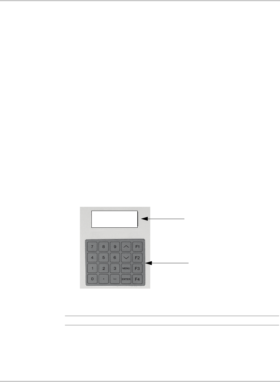
Clearing Faults Manually
152607 4–3
Clearing Faults Manually
Faults associated with a grid disturbance clear automatically. These faults include:
• 0010 (AC Frequency Low),
• 0011 (AC Frequency High),
• 0012 AC Voltage Low), and
• 0013 (AC Voltage High) only.
Once the AC voltage and frequency return to within the acceptable range, the
PV225S will clear the fault and automatically restart after a 5-minute delay. All
other faults associated with the PV225S must be circumvented and cleared
manually using the UFCU.The following procedure describes how to manually
clear a fault message from the LCD.
To clear the fault:
1. Determine the source of the fault using Table 4-1, “Fault Codes” on page 4–4.
Correct the fault condition.
2. Ensure the fault code and “
Clear Fault?
” message is displayed in the LCD.
a) If the “
Clear Fault?
” message is not shown on the second line of the
LCD, scroll through the read parameter menu with the /\ or \/ keys until
the message appears.
3. To clear the fault, press <ENTER>. The PV225S will transition to Sleeping
mode.
Figure 4-1
LCD showing Fault Code
Important::
If the fault does not clear, the fault condition has not been corrected.
LCD Display showing
Fault Code
UFCU Keypad
0071
PV SWITCH OPEN
F1 to Clear Fault?
Goal: PWR TRACKING

Troubleshooting
4–4 152607
Fault Code Descriptions
Table 4-1 provides a complete description of all the fault conditions that may
occur on the PV225S.
Table 4-1
Fault Codes
Error
Code Fault Source(s)
Fault Type
H=Hardware
S=Software Fault Description Possible Causes
0000 No Faults N/A N/A N/A
0010 AC Frequency Low S This fault indicates that the Utility
grid frequency is below or fell below
the minimum allowed value of
59.3 Hz for greater than 6 cycles.
This fault is auto-clearing. Once the
Utility grid frequency has recovered
within the acceptable operating
range, the PV225S will qualify the
value and automatically clear this
fault and resume normal operation
after 5 minute delay period.
• Utility grid frequency
fell below the allowable
limit
0011 AC Frequency High S This fault indicates that the Utility
grid frequency is above or rose above
the maximum allowed value of
60.5Hz for greater than 6 cycles. This
fault is auto-clearing. Once the Utility
grid frequency has recovered within
the acceptable operating range, the
PV225S will qualify the value and
automatically clear this fault and
resume normal operation after
5 minute delay period.
• Utility grid frequency
rose above the
allowable limit
0012 AC Voltage Low S This fault indicates that the utility
grid voltage is below or fell below the
minimum allowed value of 88% of
nominal Vac for greater than
2 seconds, or 50% of nominal VAC
for greater than 6 cycles. This fault is
auto-clearing. Once the Utility grid
voltage has recovered within the
acceptable operating range, the
PV225S will qualify the value and
automatically clear this fault and
resume normal operation after
5 minute delay period.
• Utility grid voltage fell
below the allowable
limit
• Fuses F1, F2, F3, F7, F8
or F9 blown
• P1001 on CCU2 is
loose or disconnected

Fault Code Descriptions
152607 4–5
0013 AC Voltage High S This fault indicates that the utility
grid voltage is above or rose above
the maximum allowed value of 110%
of nominal Vac for greater than 2
seconds, or 137% of nominal Vac for
greater than 2 cycles. This fault is
auto-clearing. Once the Utility grid
voltage has recovered within the
acceptable operating range, the
PV225S will qualify the value and
automatically clear this fault and
resume normal operation after
5 minute delay period.
• Utility grid voltage rose
above the allowable
limit
0014 Grid Interface Failed S This fault indicates that the PV225S
has detected an imbalance of AC
output power of 5kW or greater when
compared to the DC input power for
more than 6 seconds. This normally
means that the connection of the
PV225S to the grid has failed.
• K1 was opened while
the PV225S was
processing power
• K1 is inoperable
• K3 is inoperable
• SSR1 is inoperable
• TS1 or TS2 is open
0015 Grid Disconnection S This fault indicates that the PV225S
has detected a sudden AC voltage
increase of greater than 40% of the
nominal peak-to-peak value. This
normally is the result of a sudden
disconnection from the Utility grid
while the PV225S was processing
power.
• S1 was opened while
the PV225S was
processing power
0016 DC Contactor
Circuit
S This fault indicates that upon entering
the Power Tracking State, the
PV225S has detected that the PV
voltage has remained above the PV
Start Voltage threshold even after
commanding the DC contactor to
close. This condition is indicative of a
DC contactor circuit failure.
• K2 is inoperable
• SSR2 is inoperable
• TS1 or TS2 is open
Table 4-1
Fault Codes
Error
Code Fault Source(s)
Fault Type
H=Hardware
S=Software Fault Description Possible Causes

Troubleshooting
4–6 152607
0017 Phase Error S This fault indicates that the PV225S
has detected an incorrect phase
rotation of the incoming AC grid
voltage. This condition is indicative
of a power conductor termination
error, resulting in improper phasing
sequence.
• AC power conductors
terminated at S1-2T1,
S1-4T2, and S1-6T3 are
improperly phased.
0020 PV Over-Current S This fault indicates that the PV225S
has detected a DC current greater
than the maximum allowed value of
900 A DC.
• CT7 is inoperable
• CCU2 ±15 Vdc Power
Supply is defective
• P3 on CCU2 is loose or
disconnected
• PV system wiring short
0021 PV Over-Voltage S This fault indicates that the PV225S
has detected a DC input voltage of
greater than the maximum allowed
value of 600 Vdc.
• PV system wiring short
• Lightning strike on PV
system wiring
0023 Bus Voltage High H This fault indicates that the PV225S
has detected that the DC bus voltage
has exceeded the maximum allowed
value of 925 Vdc.
• PV system wiring short
• Lightning strike on PV
system wiring
XX31 Left Matrix Over
Current
S This fault indicates that the PV225S
has detected that the AC current on
one or more phases of the inverter
output has exceeded the maximum
allowed value of 712 Arms.
The first two digits of the fault code
indicate the particular phase where
the over current occurred as follow:
• 0131 - Matrix over current in
phase A
• 0231 - Matrix over current in
phase B
• 0431 - Matrix over current in
phase C
If more than one phase faults
simultaneously, the two first digits
are added in hexadecimal form to
indicate an over current condition in
more than one phase, thus the error
code will contain the summation of
the faulted phases.
• CT1, CT2, or CT3 are
inoperable
• CCU2 ±15 Vdc Power
Supply is defective
• P3 on CCU2 is loose or
disconnected
• AC system wiring short
Table 4-1
Fault Codes
Error
Code Fault Source(s)
Fault Type
H=Hardware
S=Software Fault Description Possible Causes

Fault Code Descriptions
152607 4–7
XX32 Right Matrix Over
Current
S This fault indicates that the PV225S
has detected that the AC current on
one or more phases of the inverter
output has exceeded the maximum
allowed value of 712 Arms.
The first two digits of the fault code
indicate the particular phase where
the over current occurred as follow:
• 0132 - Matrix over current in
phase A
• 0232 - Matrix over current in
phase B
• 0432 - Matrix over current in
phase C
If more than one phase faults
simultaneously, the two first digits
are added in hexadecimal form to
indicate an over current condition in
more than one phase, thus the error
code will contain the summation of
the faulted phases.
• CT4, CT5, or CT6 are
inoperable
• CCU2 ±15Vdc Power
Supply is defective
• P3 on CCU2 is loose or
disconnected
• AC system wiring short
0033 Ground Over
Current
S This fault indicates that the PV225S
has detected that the ground fault
current has exceeded the maximum
allowed value. This maximum
allowed value for ground fault current
is a user-configurable setting with a
range of 1 to 20 Adc. The default
setting for this value is 10 Adc.
• CT8 is inoperable
• CCU2 ±15 Vdc Power
Supply is defective
• P3 on CCU2 is loose or
disconnected
• Ground -to-AC or
DC-to-System wiring
short
0040 Programming
Software
S This code indicates that the PV225S
has detected that the system is in
Programming mode. This fault does
not indicate any malfunction with the
PV225S, but is merely an indication
that the system software is in the
process of being downloaded into the
EEPROMs of the CCU2.
Table 4-1
Fault Codes
Error
Code Fault Source(s)
Fault Type
H=Hardware
S=Software Fault Description Possible Causes

Troubleshooting
4–8 152607
0041 State Invalid S The state machine implemented
within the CCU2 system software
governs the operation of the PV225S.
This fault indicates that the PV225S
has detected an unknown system
variable and has encountered an
invalid state.
• Internal RAM error
• CPU error
0042 Serial EEPROM
Write Error
S This fault indicates that the PV225S
has detected a serial EEPROM write
error. The CCU2 controller board
performs a verification check of data
written to ROM compared to what is
read back.
• Internal ROM error
• CPU error
0043 Serial EEPROM
Timeout
S This fault indicates that the PV225S
has detected that when writing data to
the serial EEPROM, a confirmation
timer of 300mS has expired.
• Internal ROM error
• CPU error
0044 Bad NOVRAM
Memory
S This fault indicates that the PV225S
has detected that one of the two non-
volatile memory banks on the CCU2
controller board has failed. The
CCU2 performs a series of tests to
confirm the validity of the
NOVRAM, and one of the two banks
has produced errors.
• Internal NOVRAM
error
• CPU error
0045 Interrupt 2 Timeout S This fault indicates that the PV225S
has detected that an interrupt 2
timeout has occurred. The CCU2
controller board performs a
conversion validation of analog-to-
digital data within the A to D
converters. If validation of the
conversion is not performed within
500mS, an interrupt 2 timeout fault
will occur.
• Internal A to D
converter error
• CPU error
0047 Software Test S This fault indicates that the PV225S
has detected that a software test fault
has occurred. This is a simulated fault
used for debugging purposes.
Table 4-1
Fault Codes
Error
Code Fault Source(s)
Fault Type
H=Hardware
S=Software Fault Description Possible Causes

Fault Code Descriptions
152607 4–9
0048 Bad Memory S This fault indicates that the PV225S
has detected that the SRAM DIMM
on the CCU2 controller board has
failed. The CCU2 performs a series
of tests to confirm the validity of the
SRAM and the memory module has
produced errors.
• Internal SRAM error
• CPU error
XX50 Left Matrix Gate S The CCU2 controller sends digitized
timing signals for gating the IGBT’s
via the IPM driver board and bi-
directional fiber optic
communication. This fault indicates
that the PV225S has detected that an
IGBT gate drive fault has occurred in
the left matrix. An internal protection
circuit within the individual IPM
devices of the IGBT matrix also
generates a gate fault as the result of
either short circuit, over current, over
temperature, or an under voltage
condition.
The first two digits of the fault code
indicate the particular IGBT that
reported the fault, as follows:
• 0150 (A+)
• 0250 (A–)
• 0450 (B+)
• 0850 (B–)
• 1050 (C+)
• 2050 (C–)
If more than one IGBT faults
simultaneously, the two first digits
are added in hexadecimal form to
indicate that the gate drive fault has
occurred in more than one phase, thus
the error code will contain the
summation of the faulted phases.
• Fiber-optic harness is
loose or disconnected
• PS1 ±15 Vdc Power
Supply is defective
• P1 on IPM driver board
is loose or disconnected
• IPM internal error
condition
Table 4-1
Fault Codes
Error
Code Fault Source(s)
Fault Type
H=Hardware
S=Software Fault Description Possible Causes

Troubleshooting
4–10 152607
XX51 Right Matrix Gate S The CCU2 controller sends digitized
timing signals for gating the IGBT’s
via the IPM driver board and bi-
directional fiber optic
communication. This fault indicates
that the PV225S has detected that an
IGBT gate drive fault has occurred in
the right matrix. An internal
protection circuit within the
individual IPM devices of the IGBT
matrix also generates a gate fault as
the result of either short circuit, over
current, over temperature, or an under
voltage condition.
The first two digits of the fault code
indicate the particular IGBT that
reported the fault, as follows:
• 0151 (A+)
• 0251 (A–)
• 0451 (B+)
• 0851 (B–)
• 1051 (C+)
• 2051 (C–)
If more than one IGBT faults
simultaneously, the two first digits
are added in hexadecimal form to
indicate that the gate drive fault has
occurred in more than one phase, thus
the error code will contain the
summation of the faulted phases.
• Fiber-optic harness is
loose or disconnected
• PS1 ±15 Vdc Power
Supply is defective
• P1 on IPM driver board
is loose or disconnected
• IPM internal error
condition
XX60 Left Matrix
Temperature
S This fault indicates that the PV225S
has detected that the temperature of
the left IGBT matrix aluminum
heatsink has exceeded the maximum
allowed value of 95 °C.
• Fuses F15 or F16 blown
• External cooling fan
inoperable
• Air flow on heat sink
impeded due to
accumulation of debris
• Operation above rated
ambient temperature for
an extended period of
time
Table 4-1
Fault Codes
Error
Code Fault Source(s)
Fault Type
H=Hardware
S=Software Fault Description Possible Causes

Fault Code Descriptions
152607 4–11
XX61 Right Matrix
Temperature
S This fault indicates that the PV225S
has detected that the temperature of
the right IGBT matrix aluminum
heatsink has exceeded the maximum
allowed value of 95 °C.
• Fuses F15 or F16 blown
• External cooling fan
inoperable
• Air flow on heat sink
impeded due to
accumulation of debris
• Operation above rated
ambient temperature for
an extended period of
time
0070 Interlock Activated H This fault indicates that the PV225S
has detected that the door of the Main
Inverter Enclosure is open and the
door interlock switch is in the active
position. This fault is primarily for
personnel safety. Opening the door of
the Main Inverter Enclosure while the
PV225S is processing power will
cause an immediate orderly shutdown
of the system.
• Door is open and
interlock switch is
active
• Interlock switch is
inoperable
• P2 or P3 on CCU2 is
loose or disconnected
• CCU2 ±15Vdc Power
Supply is defective
0071 PV Switch Open H This fault indicates that the PV225S
has detected that the DC Disconnect
Switch (S2) is open and the auxiliary
switch is in the active position. This
fault is primarily for personnel safety.
Opening the DC disconnect switch
while the PV225S is processing
power will cause an immediate
orderly shutdown of the system.
• DC disconnect switch is
open and auxiliary
switch is active
• Auxiliary switch is
inoperable
• P2 or P3 on CCU2 is
loose or disconnected
• CCU2 ±15 Vdc Power
Supply is defective
0075 Shutdown Remotely S This fault indicates that the PV225S
has detected that the system was
commanded via the GUI to transition
to the Shutdown State. This fault is
not indicative of a failure or
malfunction, but primarily used to
disable the system remotely.
• Remote Shutdown
command via the GUI
Table 4-1
Fault Codes
Error
Code Fault Source(s)
Fault Type
H=Hardware
S=Software Fault Description Possible Causes

Troubleshooting
4–12 152607
0080 Left Matrix Not ON S This fault indicates that the PV225S
has detected that the left IGBT matrix
(FPGA) was not enabled after having
sent a command for it to turn on. The
CCU2 sends an acknowledge bit to
confirm the command is received.
This fault is primarily a watch-dog
between software and hardware to
ensure control of the left IGBT matrix
(FPGA).
• Software acknowledge
bit not accepted
• FPGA inoperable
0081 Right Matrix Not
ON
S This fault indicates that the PV225S
has detected that the right IGBT
matrix (FPGA) was not enabled after
having sent a command for it to turn
on. The CCU2 sends an acknowledge
bit to confirm the command is
received. This fault is primarily a
watch-dog between software and
hardware to ensure control of the
right IGBT matrix (FPGA).
• Software acknowledge
bit not accepted
• FPGA inoperable
0084 Left Matrix Not OFF S This fault indicates that the PV225S
has detected that the left IGBT matrix
(FPGA) was not disabled after having
sent a command for it to turn off. The
CCU2 sends an acknowledge bit to
confirm the command is received.
This fault is primarily a watch-dog
between software and hardware to
ensure control of the left IGBT matrix
(FPGA).
• Software acknowledge
bit not accepted
• FPGA inoperable
0085 Right Matrix Not
OFF
S This fault indicates that the PV225S
has detected that the right IGBT
matrix (FPGA) was not disabled after
having sent a command for it to turn
off. The CCU2 sends an acknowledge
bit to confirm the command is
received. This fault is primarily a
watch-dog between software and
hardware to ensure control of the
right IGBT matrix (FPGA).
• Software acknowledge
bit not accepted
• FPGA inoperable
Table 4-1
Fault Codes
Error
Code Fault Source(s)
Fault Type
H=Hardware
S=Software Fault Description Possible Causes

Fault Code Descriptions
152607 4–13
F000 Shipping Software S This fault indicates that the PV225S
has detected that the CCU2 controller
board has shipping software installed.
This software is not operational
software. The correct system
software for the PV225S must be
downloaded into the CCU2 controller
board.
F100 Software Restarted S This fault indicates that the PV225S
has detected that the system software
has been re-booted. This is not a true
fault, and does not effect the
operation of the PV225S. It is
primarily used as a watchdog for
debugging purposes.
Table 4-1
Fault Codes
Error
Code Fault Source(s)
Fault Type
H=Hardware
S=Software Fault Description Possible Causes
4–14
5Preventative
Maintenance
Chapter 5, “Preventative Maintenance” contains information and
procedures for performing preventative maintenance on the PV225S
225 kW Grid-Tied Photovoltaic Inverter.
Preventative Maintenance
5–2 152607
Maintenance Safety
Prior to following any Maintenance Procedures, follow the System Shutdown and
Lock-out and Tag procedure.
Operational Safety Procedures
Never work alone when servicing this equipment. A team of two is required until
the equipment is properly de-energized, locked-out and tagged, and verified de-
energized with a meter. Thoroughly inspect the equipment prior to energizing.
Verify that no tools or equipment have inadvertently been left behind.
De-Energize/Isolation Procedure
The following procedure should be followed to de-energize the PV225S for
maintenance:
To isolate the PV225S:
1. Turn the ON/OFF switch to the OFF position.
2. Open the DC Disconnect Switch.
3. Open the AC Disconnect Switch.
4. Open the utility connection circuit breaker.
5. Install lockout devices on the utility connection circuit breaker and DC
Disconnect Switch.
WARNING: Shock Hazard
Review the system schematic for the installation to verify that all available energy sources
are de-energized. DC bus voltage may also be present. Be sure to wait the full 5 minutes to
allow the capacitors to discharge completely.
WARNING: Shock Hazard
The terminals of the DC input may be energized if the PV arrays are energized. In
addition, allow 5 minutes for all capacitors within the main enclosure to discharge after
disconnecting the PV225S from AC and DC sources.

Maintenance Safety
152607 5–3
Lockout and Tag
Safety requirements mandate that this equipment not be serviced while energized.
Power sources for the PV225S must be locked-out and tagged prior to servicing.
Each energy source should have a padlock and tag installed on each energy source
prior to servicing.
The PV225S can be energized from both the AC source and the DC source. To
ensure that the inverter is de-energized prior to servicing, lock out and tag the
PV225S using the following procedure.
1. Open, lockout, and tag the incoming power at the utility main circuit breaker.
2. Open, lockout, and tag the AC Disconnect Switch (S1) on AC interface
assembly. See Figure 1-8 on page 1–12 for the location of the AC Disconnect
Switch.
3. Open, lockout, and tag the DC Disconnect Switch (S2) on DC interface
assembly. See Figure 1-8 on page 1–12 for the location of the DC Disconnect
Switch.
4. Using a confirmed, accurate meter, verify all power to the inverter is de-
energized. A confirmed, accurate meter must be verified on a known voltage
before use. Ensure that all incoming energy sources are de-energized by
checking the following locations.
a) Inverter Terminals: TB5, TB6, and TB7 (Phase A, B, C)
See Figure 5-1 on page 5–4.
b) Utility Terminals: Top of S1-2T1, S1-4T2, and S1-6T3
See Figure 5-2 on page 5–4.
c) PV Terminals: Bottom of S2-6, K2-6T3, and TB4 (PV+, PV-, GND)
See Figure 5-3 on page 5–5.
WARNING: Shock Hazard
Review the system schematic for the installation to verify that all available energy sources
are de-energized. DC bus voltage may also be present. Be sure to wait the full 5 minutes to
allow the capacitors to discharge completely.
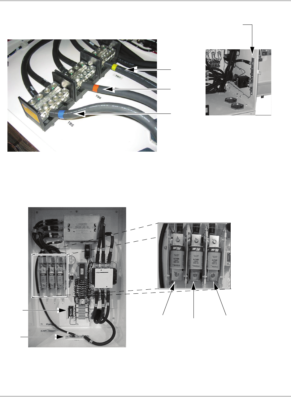
Preventative Maintenance
5–4 152607
Figure 5-1
Inverter AC Terminal Locations in the Main Inverter Enclosure
Figure 5-2
Utility AC Terminal Connections in the AC Interface Enclosure
AC Ground Bar (TB1)
to be used for the
Chassis Ground
TB6
TB5
TB7
AC Interface Enclosure
Enlargement of
Terminal Connectors
in the AC Interface
Enclosure
AC Interface Enclosure
S1-4T2
(B phase)
S1-2T1
(A phase)
S1-6T3
(C phase)
TB11
TB12
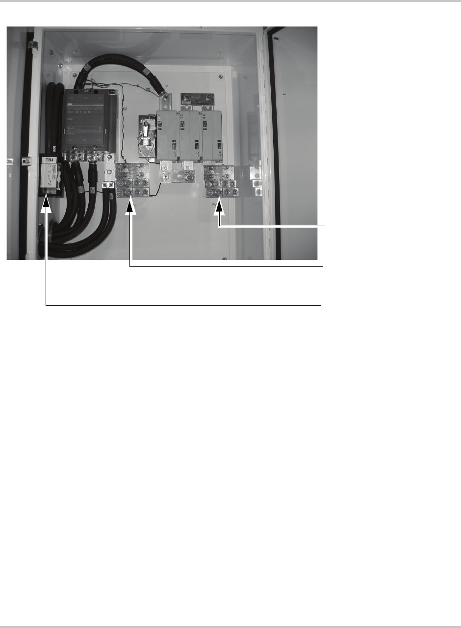
Maintenance Safety
152607 5–5
Figure 5-3
PV Terminal Locations
PV NEGative (K2-6T3)
PV POSitive (S2-6)
PV GrouND (TB4)

Preventative Maintenance
5–6 152607
Periodic Maintenance
Xantrex Technology recommends that the following preventative maintenance
procedures be carried out on the PV225S.
Monthly Intervals or As Required
Perform the following preventative maintenance tasks on a monthly basis or as
required.
Aluminum Extrusion Heatsinks
❐Inspect the aluminum extrusion heatsinks and external cooling fans for
accumulation of dirt and debris. Accumulation of dirt and debris on the
aluminum extrusion heatsinks and external cooling fans will decrease their
ability to transfer heat, which may cause the PV225S to enter a fault state
based upon an over-temperature alarm. Remove and clean if debris is present.
Fan Operation
❐Verify proper operation of the external cooling fans (B1 and B2) located
above the matrix aluminum extrusion heatsinks. These fans operate when the
K1 contactor is closed. If present, remove any debris from the fans.
Internal Circulation Fan
❐Verify the internal circulation fan (B3) is operating whenever there is utility
power applied to the PV225S.
Inductor Enclosure Cooling Fans
❐Verify that the inductor enclosure cooling fans (B4 and B5) operate whenever
the PV225S is processing power. The airflow direction should be from the
outside, forcing air into the enclosure. If present, remove any debris from the
fans.

Periodic Maintenance
152607 5–7
Six-month Intervals
Perform the following preventative maintenance tasks on a six-month basis or as
required.
Enclosure Seals
❐Inspect the enclosure access panel seal. If damaged, replace with equivalent
closed cell foam gasket. Call your Xantrex Technology distributor for factory
replacements or specifications.
Electrical Connections
❐Inspect the condition of all wiring within and interfacing to the PV225S.
❐Inspect all compression-type cable terminations and box-type connections
within the AC and DC Interface Enclosures, Main Inverter Enclosure, and
Transformer Enclosure for damage caused from high temperature.
❐Also check these terminations and connections for signs of corrosion. If any
cabling or wiring within and interfacing to the PV225S are found to be or are
suspected to be unacceptable, contact your Xantrex Technology distributor for
factory replacements or recommendations. Replacement of any damaged
wires will be necessary.
❐Verify all mechanical connections are sufficiently tightened. Verify all
conduction surfaces are clean and free of corrosion. Mechanical electrical
connections may loosen over time primarily due to thermal cycling during
normal operation. As electrical connections loosen, impedance will increase
at the connection, eventually leading to possible fire and component damage.
It is critical to check all electrical connections every six months.
See termination torque specifications for AC connections in Table A-4 on
page A–4. See termination torque specifications for DC connections in Table A-5
on page A–4.
Inductor Enclosure
❐Remove the access panels on the inductor enclosure and inspect for any
accumulated dirt and debris within the enclosure. Vacuum enclosure
whenever dust or dirt is present.
5–8
ASpecifications
Appendix A provides the environmental and electrical specifications
for the PV225S 225 kW Grid-Tied Photovoltaic Inverter.

Specifications
A–2 152607
System Specifications
The PV225S has been designed for photovoltaic power systems, which operate
within the following specifications.
Environmental Specifications
The following environmental specifications are the same for both models of the
PV225S 225 kW Grid-Tied Photovoltaic Inverter.
CAUTION: Equipment Damage
Operation of the PV225S in a manner other than specified in this manual may cause
damage to the PV225S and other system components and will void the terms of the
warranty.
Table A-1
Environmental Specifications
Specification Value
Dimensions
Inverter and DC Interface
Transformer and AC Interface
Overall System Footprint:
Layout Option A
Layout Option B
88.5 in H x 80 in W x 32 in D (225 cm H x 203 cm W x 81 cm)
49.5 in H x 61.5 in W x 35.5 in D (126 cm H x 156 cm W x 90 cm D)
14 ft W x 5 ft L (approximate) (4.3 m x 1.5 m)
10 ft W x 9 ft L (approximate) (3 m W x 2.7 m L)
Weight
Inverter and DC Interface
Transformer and AC Interface
Overall Weight
2300 lbs (approximate)
2350 lbs (approximate)
4650 lbs (approximate)
Allowable Ambient Temperature
Operating
Storage
-20 °C to 50 °C Maximum
-40 °C to 50 °C Maximum
Relative Humidity To 95%, Non-condensing
Elevation Power Derated above 6600 ft
Clearance (ventilation and
serviceability)
In front of access doors: 36 in (91 cm)
In front of access panels: 36 in (91 cm)
Sides: 12 in (30 cm)
Back: 6 in (15 cm)
Maximum Distance between Main
Inverter Enclosure and AC Interface/
Transformer Enclosure
15 ft (4.5 m)
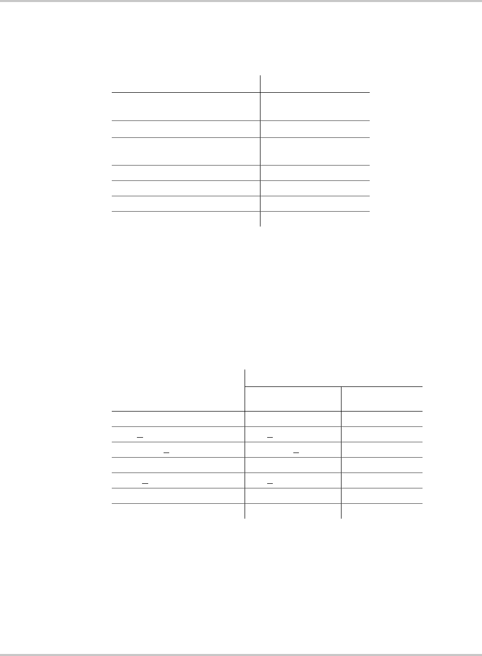
System Specifications
152607 A–3
Electrical Specifications
Table A-2 provides the AC and DC specifications for the PV225S.
Over Voltage, Under Voltage and Frequency Ranges
Table A-3 provides the over voltage, under voltage, over-frequency, and under-
frequency detection limits for the PV225S. These detection limits have been
factory tested and deemed to be in compliance with IEEE-292 and UL 1741
requirements for utility interaction.
Table A-2
Electrical Specifications
Specification PV225S-480-P
Nominal AC Input Voltage
(+10% to -12% acceptable range)
480 Vac
(422 to 528 Vac)
Maximum AC Output Current 271 Arms
Nominal AC Input Frequency
(+0.5 to -0.7 Hz acceptable range)
60 Hz
(59.3 to 60.5 Hz)
Output Power 225 kW
Peak Power Tracking Window 300 to 600 Vdc
Maximum Open Circuit Voltage 600 Vdc
Maximum DC Input Current 781 amps
Table A-3
Over/Under Voltage and Over/Under Frequency Ranges
Vac Condition
(% of Nominal)
PV225S-480-P
Voltage Range Trip Time
Vac < 50% Vac < 240 6 cycles
50% < Vac < 88% 240 < Vac < 422 2 seconds
88% < Vac < 110% 422 < Vac < 528 normal operation
110% < Vac < 137% 528 < Vac < 657 2 seconds
137% < Vac 657 < Vac 2 cycles
f < rated -0.7 f < 59.3 6 cycles
f > rated +0.5 f > 60.5 6 cycles

Specifications
A–4 152607
Wire Gauge and Torque Requirements
Table A-4 provides acceptable wire gauges, bolt sizes, and torque values for AC
terminal connections.
Table A-5 provides acceptable wire gauges, bolt sizes, and torque values to be
connected to the PV225S DC terminal connections.
Table A-4
AC Terminal Wire Gauge, Bolt Size, and Torque Values
AC Terminal
Connections
Acceptable Wire Size Range
(both models)
Bolt (Hardware)
Size
To r qu e
Requirements
TB1
(Chassis Ground)
500 MCM to #4 AWG (1 stud per pole) 3/8-16 420 in-lb (47.5 Nm)
TB12
(System Ground)
500 MCM to #4 AWG (1 stud per pole) 3/8-16 420 in-lb (47.5 Nm)
TB11 (Neutral) 500 MCM to #4 AWG (1 stud per pole) 3/8-16 228 in-lb (25.7 Nm)
S1-2T1, S1-4T2,
S1-6T3
350 MCM to #6 AWG (1 stud per phase) M10 310 in-lb (35.0 Nm)
T6-X1, T6-X2, T6-
X3
350 MCM to #6 AWG (2 stud per phase) 3/8-16 420 in-lb (47.45 Nm)
TB5, TB6, TB7 350 MCM to #4 AWG (6 openings per phase) 3/8 Hex 375 in-lb (42.4 Nm)
Table A-5
DC Terminal Wire Gauge, Bolt Size, and Torque Values
DC Terminal
Connections
Acceptable Wire Size Range
(both models)
Bolt (Hardware)
Size
Torque
Requirements
S2-6, K2-6T3, TB4 600 MCM to #4 AWG (2 openings per pole) 1/2 Hex 600 in-lb (67.8 Nm)
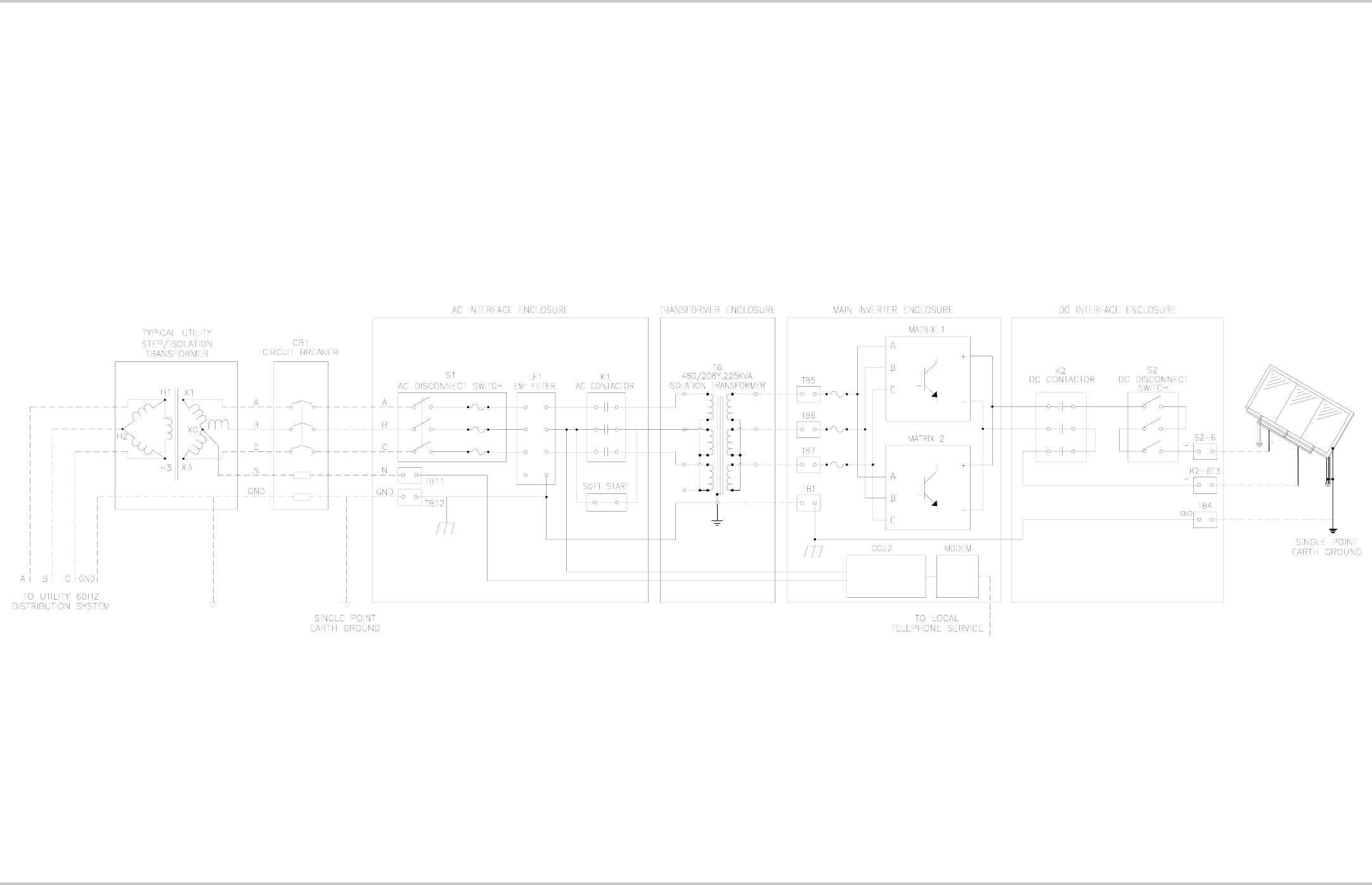
Appendix A Schematics
152607 A-5
Figure A-1
Electrical Diagram (sample)
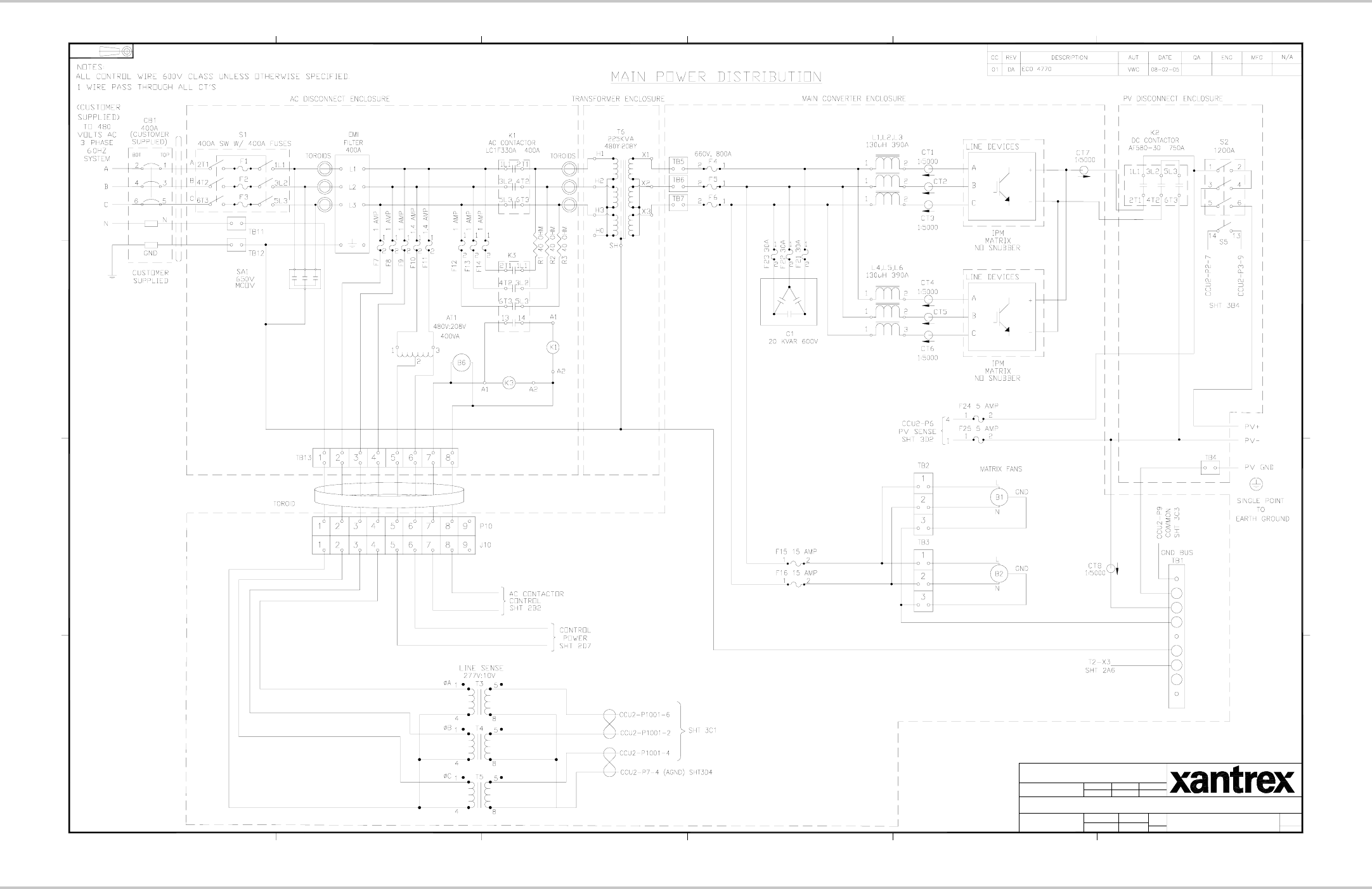
Schematics Appendix A
A-6 152607
Figure A-2
PV225S Schematic for Main Power Distribution (152812 A1)
2
REVISIONS
1
A
6
B
5
C
D
6
PROJECTION
3RD ANGLE
5
43
4 3
COPYRIGHT XANTREX TECHNOLOGY INC.. THIS DOCUMENT IS THE PROPERTY OF
XANTREX TECHNOLOGY INC., AND SHALL NOT BE REPRODUCED, COPIED, OR USED AS THE
BASIS FOR THE MANUFACTURE OR SALE OF EQUIPMENT, WITHOUT THE EXPRESS WRITTEN
PERMISSION OF: XANTREX TECHNOLOGY INC.
2
D
ANGLES
AUT
X.XX X.XXX
SIZE
TITLE:
CONFIDENTIAL INFORMATION OF XANTREX TECHNOLOGY INC.
TOLERANCES:
(UNLESS OTHERWISE SHOWN)
SCALE:
DIMENSIONS ARE IN
INCHES UNLESS
OTHERWISE SHOWN DES
TM
REV.
OF
SHT
DWG No.
A
1
B
C
D
SCHEMATIC, SYSTEM, PV225S-480-P
152812 A
B. ECCLES 12-11-03
N/A N/A NTS
± .02 ± .005 ± 1.0°
13
2004
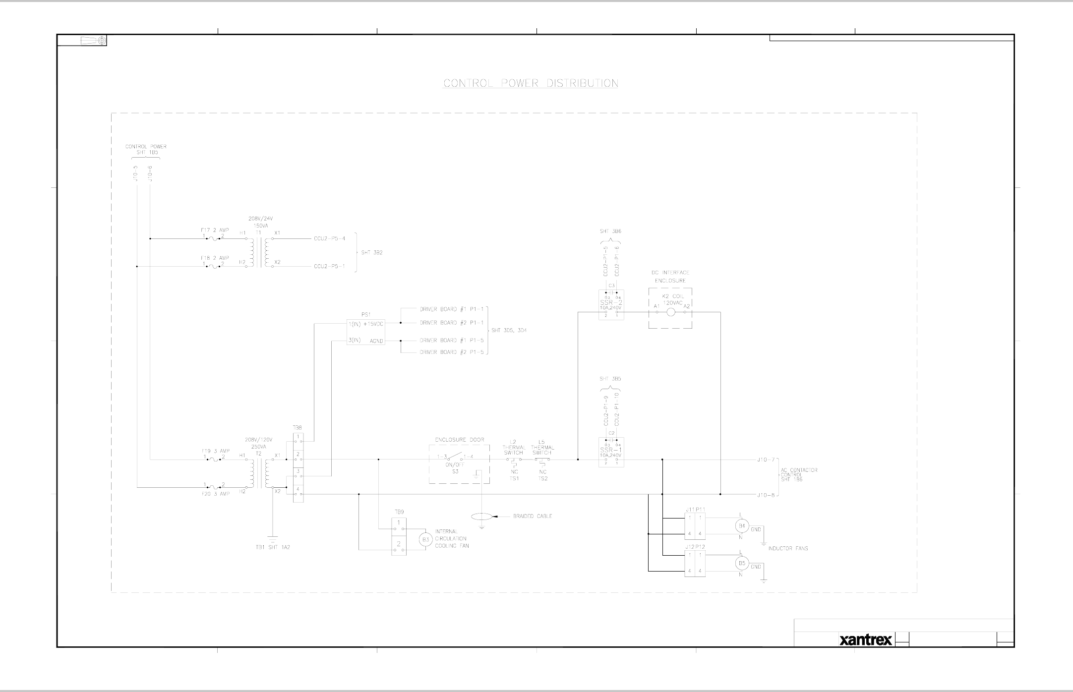
Appendix A Schematics
152607 A-7
Figure A-3
PV225S Schematic for Control Power Distribution (152812 A2)
REVISIONS: SEE SHEET 1
6
B
A
5
C
D
4 3
DIMENSIONS ARE IN
INCHES UNLESS
OTHERWISE SHOWN
2
TITLE:
6
PROJECTION
3RD ANGLE
54 3 2
1
DWG No.
TM
D
SCALE:
SIZE
SHT
OF
REV.
B
A
C
D
1
SCHEMATIC, SYSTEM, PV225S-480-P
152812 A
NTS 23
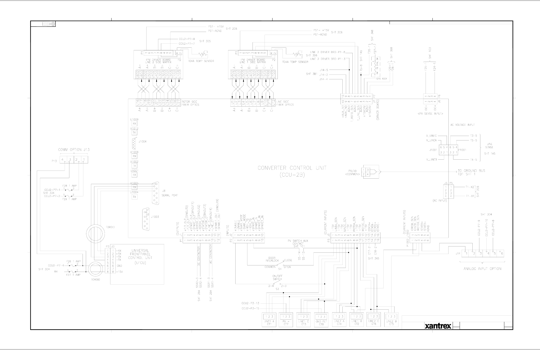
Schematics Appendix A
A-8 152607
Figure A-4
PV225S Schematic for Converter Control Unit (152812 A3)
REVISIONS: SEE SHEET 1
6
B
A
5
C
D
4 3
DIMENSIONS ARE IN
INCHES UNLESS
OTHERWISE SHOWN
2
TITLE:
6
PROJECTION
3RD ANGLE
54 3 2
1
DWG No.
TM
D
SCALE:
SIZE
SHT
OF
REV.
B
A
C
D
1
SCHEMATIC, SYSTEM, PV225S-480-P
152812 A
NTS 33

152607 WA–1
Warranty and Product Information
Xantrex Limited Warranty
PV225S GRID TIE INVERTER
(PV SERIES INVERTER)
1. What does this warranty cover and how long does it last?
This Limited Warranty is provided by Xantrex Technology Inc. (“Xantrex”) and covers defects in workmanship and
materials in your PV Series Inverter. This warranty lasts for a Warranty Period of 5 years from the date of purchase
at point of sale to you, the original end user customer.
2. What will Xantrex do?
Xantrex will, at its option, repair or replace the defective product free of charge, provided that you notify Xantrex of
the product defect within the Warranty Period, and provided that Xantrex through inspection establishes the existence
of such a defect and that it is covered by this Limited Warranty.
Xantrex will, at its option, use new and/or reconditioned parts in performing warranty repair and building
replacement products. Xantrex reserves the right to use parts or products of original or improved design in the repair
or replacement. If Xantrex repairs or replaces a product, its warranty continues for the remaining portion of the
original Warranty Period or 90 days from the date of the return shipment to the customer, whichever is greater. All
replaced products and all parts removed from repaired products become the property of Xantrex.
Xantrex covers both parts and labor necessary to repair the product, and return shipment to the customer via a
Xantrex-selected non-expedited surface freight within the contiguous United States and Canada. Alaska and Hawaii
are excluded. Contact Xantrex Customer Service for details on freight policy for return shipments outside of the
contiguous United States and Canada.
3. What does this warranty not cover?
This Limited Warranty does not cover normal wear and tear of the product or costs related to the removal,
installation, or troubleshooting of the customer’s electrical systems. This warranty does not apply to and Xantrex will
not be responsible for any defect in or damage to the product:
a) if it has been misused, neglected, improperly installed, physically damaged or altered, either internally or exter-
nally, or damaged from improper use or use in an unsuitable environment;
b) if it has been subjected to fire, water, generalized corrosion, biological infestations, or input voltage that creates
operating conditions beyond the maximum or minimum limits listed in the Xantrex product specifications
including high input voltage from generators and lightning strikes;
c) if repairs have been done to it other than by Xantrex or its authorized service centers (hereafter “ASCs”);
d) if it is used as a component part of a product expressly warranted by another manufacturer; and
e) if its original identification (trade-mark, serial number) markings have been defaced, altered, or removed.

Warranty and Return
WA–2 152607
4. Product Disclaimer
THIS LIMITED WARRANTY IS THE SOLE AND EXCLUSIVE WARRANTY PROVIDED BY XANTREX IN CONNECTION WITH YOUR
XANTREX PRODUCT AND IS, WHERE PERMITTED BY LAW, IN LIEU OF ALL OTHER WARRANTIES, CONDITIONS,
GUARANTEES, REPRESENTATIONS, OBLIGATIONS AND LIABILITIES, EXPRESS OR IMPLIED, STATUTORY OR OTHERWISE IN
CONNECTION WITH THE PRODUCT, HOWEVER ARISING (WHETHER BY CONTRACT, TORT, NEGLIGENCE, PRINCIPLES OF
MANUFACTURER’S LIABILITY, OPERATION OF LAW, CONDUCT, STATEMENT OR OTHERWISE), INCLUDING WITHOUT
RESTRICTION ANY IMPLIED WARRANTY OR CONDITION OF QUALITY, MERCHANTABILITY OR FITNESS FOR A PARTICULAR
PURPOSE. ANY IMPLIED WARRANTY OF MERCHANTABILITY OR FITNESS FOR A PARTICULAR PURPOSE TO THE EXTENT
REQUIRED UNDER APPLICABLE LAW TO APPLY TO THE PRODUCT SHALL BE LIMITED IN DURATION TO THE PERIOD
STIPULATED UNDER THIS LIMITED WARRANTY.
IN NO EVENT WILL XANTREX BE LIABLE FOR ANY SPECIAL, INDIRECT, INCIDENTAL OR CONSEQUENTIAL DAMAGES,
LOSSES, COSTS OR EXPENSES HOWEVER ARISING WHETHER IN CONTRACT OR TORT INCLUDING WITHOUT RESTRICTION
ANY ECONOMIC LOSSES OF ANY KIND, ANY LOSS OR DAMAGE TO PROPERTY, ANY PERSONAL INJURY, ANY DAMAGE OR
INJURY ARISING FROM OR AS A RESULT OF MISUSE OR ABUSE, OR THE INCORRECT INSTALLATION, INTEGRATION OR
OPERATION OF THE PRODUCT.
5. Limitations to Product Disclaimer
If this product is a consumer product, federal law does not allow an exclusion of implied warranties. To the extent you
are entitled to implied warranties under federal law, to the extent permitted by applicable law they are limited to the
duration of this Limited Warranty. Some states and provinces do not allow limitations or exclusions on implied
warranties or on the duration of an implied warranty or on the limitation or exclusion of incidental or consequential
damages, so the above limitation(s) or exclusion(s) may not apply to you. This Limited Warranty gives you specific
legal rights. You may have other rights which may vary from state to state or province to province.
6. Information Disclaimer
WITHOUT LIMITING THE GENERALITY OF THE FOREGOING, UNLESS SPECIFICALLY AGREED TO BY IT IN WRITING,
XANTREX
(a) MAKES NO WARRANTY AS TO THE ACCURACY, SUFFICIENCY OR SUITABILITY OF ANY TECHNICAL OR OTHER
INFORMATION PROVIDED IN MANUALS OR OTHER DOCUMENTATION PROVIDED BY IT IN CONNECTION WITH THE
PRODUCT; AND
(b) ASSUMES NO RESPONSIBILITY OR LIABILITY FOR LOSSES, DAMAGES, COSTS OR EXPENSES, WHETHER SPECIAL,
DIRECT, INDIRECT, CONSEQUENTIAL OR INCIDENTAL, WHICH MIGHT ARISE OUT OF THE USE OF SUCH INFORMATION.
THE USE OF ANY SUCH INFORMATION WILL BE ENTIRELY AT THE USER’S RISK.
7. WARNING: LIMITATIONS ON USE
Please refer to your product user manual for limitations on uses of the product. Specifically, please note
that the PV Series Inverter is not intended for use in connection with life support systems and Xantrex
makes no warranty or representation in connection with any use of the product for such purposes.
Xantrex Technology Inc.
161-G South Vasco Road
Livermore, CA 94551
USA

Warranty and Return
152607 WA–3
PRODUCT REGISTRATION
To ensure the fastest possible service, please ensure your system information submitted to Xantrex. Please
fill the required information in and send a copy of this page to Xantrex Technology Inc. along with a copy
of the GUI Commissioning File.
Fax number: 925 455 0382
Mail to: Xantrex Technology Inc.
161-G South Vasco Road
Livermore, CA 94551
Attention: Customer Service
USA
Note: Please email the PV225S Commissioning Report File to: pvcommissioningreport@xantrex.com.
Customer Company Name: __________________________________
Project Name: __________________________________
System Location Information:
Street __________________________________
City __________________________________
State / Zip Code __________________________________
Xantrex Inverter Model: __________________________________
Serial Number of Inverter: __________________________________
Serial Number of Isolation Transformer: __________________________________
Name of Distributor (if applicable): __________________________________
__________________________________________ __________________________________________
Xantrex Authorized Signature Customer Authorized Signature
Date: Date:
WA–4
A
AC Interface Enclosure 1–8
Accumulated Values 1–18
Anti-Island Protection 1–5
Auto-restart Feature 2–23
Autorun 2–26
C
Clearing Faults Manually 4–3
Command Prompt 2–27
Commissioning 3–2
Communication Enclosure 1–9
Communications 2–25
Configurable Parameters 1–18
Controls 1–10
Converter Control Unit (CCU2) 1–7
D
Data Log Acquisition 1–18
Data Logging 1–13
DC Interface Enclosure 1–8
Direct Connection 2–32
Disconnect Switches 1–12
E
EMI output filter 1–2
enclosures 1–6
F
Fault Code Descriptions 4–4
Fault Log Acquisition 1–18
Fault Reporting and Logging 1–13
Faults 2–2
Faults and Fault Codes 4–2
G
General Troubleshooting 4–2
Graphic Data Analysis 1–18
grid-connected photovoltaic arrays 1–2
GUI Help 2–37
GUI Software
Starting the Software Setup Program 2–26
System Requirements 2–26
I
Inductor Enclosure 1–7
Installation 2–28
integrated controller 1–2
Internal Metrics 1–18
Isolation Procedure 5–2
L
Lockout and Tag 5–3
M
Main Enclosure Door Interlock Switch 1–10
Main Inverter Enclosure 1–7
Maintenance Safety 5–2
O
On/Off Switch 1–11
Operating States 2–4
Fault 2–5
Manual Current 2–5
Matrix Test 2–5
Power Tracking 2–4
Shutdown 2–5
Transition 2–4
Operation Features 1–2
Automatic Sleep Test 2–5
DC Overvoltage Detection 1–5
Fixed Unity Power Factor Operation 1–2
Peak Power Tracking 1–3
Utility Voltage/Frequency Fault Automatic Reset 1–4
Operational Safety Procedures 5–2
Operational Values 1–18
Operator Interface 2–6
Automatic State Transitions 2–22
Changing Write Parameter Values 2–16
Commanding Goal State Changes 2–20
Keypad Operation 2–6
Manual State Transitions 2–22
Setting the Date and Time 2–21
P
Period Maintenance
Monthly 5–6
Six month intervals 5–7
Index

Index
IX–2 152607
Power Distribution Panel 1–7
Power Electronics Matrix 1–7
PV Ground Fault Detection 1–5
R
Remote Monitor and Control Features 1–18
Remote/LAN Connection 2–31
Running the GUI 2–31
S
Self-protection features 1–2
Shutdown 2–24
Specifications A–2
Electrical A–3
Environmental A–2
Over Voltage, Under Voltage and Frequency Ranges
A–3
Startup 2–24
System Operation 2–2
T
Three-phase power conversion system 1–2
Torque and Wire Gauge Specifications A–4
Transformer Enclosure 1–8

Xantrex Technology Inc.
1 800 670 0707 Tel toll free NA
1 360 925 5097 Tel direct
1 800 994 7828 Fax toll free NA
1 360 925 5143 Fax direct
customerservice@xantrex.com
www.xantrex.com
152607 PC Printed in USA
