Xantrex Xmp 2600 Users Manual Programming
XMP 2600 to the manual 73adc12f-b03b-4503-9a1c-e457a41a4b99
2015-02-03
: Xantrex Xantrex-Xmp-2600-Users-Manual-473801 xantrex-xmp-2600-users-manual-473801 xantrex pdf
Open the PDF directly: View PDF ![]() .
.
Page Count: 93
Smart choice for power
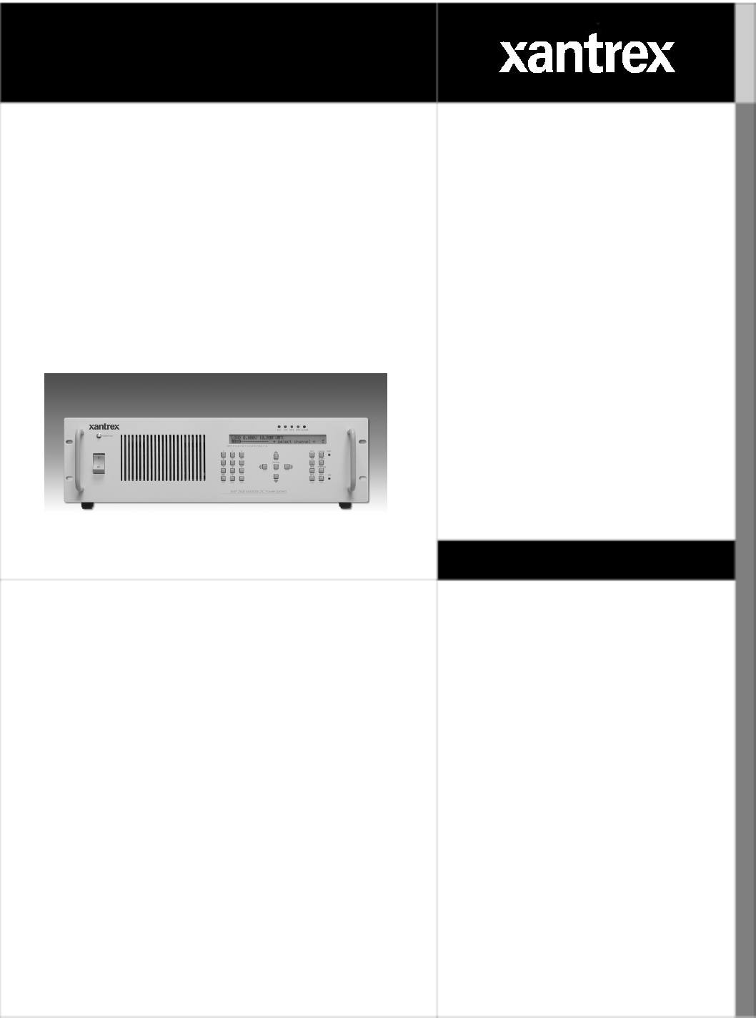
XMP 2600
Programming Manual
Xantrex
Multiple Output
Power System
XMP 2600
www.xantrex.com

Rev. 1.1 9/2003
XMP 2600
Programming Manual
This document contains proprietary information. All rights reserved. Do not reproduce this
document or part of it. Do not translate to any other language.
The information contained herein is subject to change without notice.
What does this warranty cover and how long does it
last?
Limited
Warranty
This Limited Warranty is provided by Xantrex Technology, Inc. (“Xantrex”) and
covers defects in workmanship and materials in your XMP 2600 Power Supply. This
warranty lasts for a Warranty Period of 3 years from the date of purchase at point of
sale to you, the original end user customer.
What will Xantrex do?
Xantrex will, at its option, repair or replace the defective product free of charge,
provided that you notify Xantrex of the product defect within the Warranty Period,
and provided that Xantrex through inspection establishes the existence of such a
defect and that it is covered by this Limited Warranty.
Xantrex will, at its option, use new and/or reconditioned parts in performing
warranty repair and building replacement products. Xantrex reserves the right to use
parts or products of original or improved design in the repair or replacement. If
Xantrex repairs or replaces a product, its warranty continues for the remaining
portion of the original Warranty Period or 90 days from the date of the return
shipment to the customer, whichever is greater. All replaced products and all parts
removed from repaired products become the property of Xantrex.
Xantrex covers both parts and labor necessary to repair the product, and return
shipment to the customer via a Xantrex-selected non-expedited surface freight
within the contiguous United States and Canada. Alaska and Hawaii are excluded.
Contact Xantrex Customer Service for details on freight policy for return shipments
outside of the contiguous United States and Canada.
How do you get service?
If your product requires troubleshooting or warranty service, contact your merchant.
If you are unable to contact your merchant, or the merchant is unable to provide
service, contact Xantrex directly at:
Phone: 604 422 2777
Toll Free North America: 1 800 670 0707
Fax: 604 420 2145
Email: customerservice@xantrex.com
Direct returns may be performed according to the Xantrex Return Material
Authorization Policy. For some products, Xantrex maintains a network of regional
Authorized Service Centers. Call Xantrex or check our website to see if your
product can be repaired at one of these facilities.
In any warranty claim, dated proof of purchase must accompany the product and the
product must not have been disassembled or modified without prior written
authorization by Xantrex.
Proof of purchase may be in any one of the following forms:
The dated purchase receipt from the original purchase of the product
at point of sale to the end user, or
The dated dealer invoice or purchase receipt showing original
equipment manufacturer (OEM) status, or
The dated invoice or purchase receipt showing the product exchanged
under warranty
b XMP 2600 Programming Manual rev. 1.1
What does this warranty not cover?
This Limited Warranty does not cover normal wear and tear of the product or costs
related to the removal, installation, or troubleshooting of the customer’s electrical
systems. This warranty does not apply to and Xantrex will not be responsible for any
defect in or damage to:
a. the product if it has been misused, neglected, improperly installed, physically
damaged or altered, either internally or externally, or damaged from improper
use or use in an unsuitable environment;
b. the product if it has been subjected to fire, water, generalized corrosion,
biological infestations, and high input voltage from lightning strikes;
c. the product if repairs have been done to it other than by Xantrex or its
authorized service centers (hereafter “ASCs”);
d. the product if it is used as a component part of a product expressly warranted by
another manufacturer;
e. the product if its original identification (trade-mark, serial number) markings
have been defaced, altered, or removed.
Product
Disclaimer
THIS LIMITED WARRANTY IS THE SOLE AND EXCLUSIVE WARRANTY
PROVIDED BY XANTREX IN CONNECTION WITH YOUR XANTREX
PRODUCT AND IS, WHERE PERMITTED BY LAW, IN LIEU OF ALL OTHER
WARRANTIES, CONDITIONS, GUARANTEES, REPRESENTATIONS,
OBLIGATIONS AND LIABILITIES, EXPRESS OR IMPLIED, STATUTORY OR
OTHERWISE IN CONNECTION WITH THE PRODUCT, HOWEVER ARISING
(WHETHER BY CONTRACT, TORT, NEGLIGENCE, PRINCIPLES OF
MANUFACTURER’S LIABILITY, OPERATION OF LAW, CONDUCT,
STATEMENT OR OTHERWISE), INCLUDING WITHOUT RESTRICTION
ANY IMPLIED WARRANTY OR CONDITION OF QUALITY,
MERCHANTABILITY OR FITNESS FOR A PARTICULAR PURPOSE. ANY
IMPLIED WARRANTY OF MERCHANTABILITY OR FITNESS FOR A
PARTICULAR PURPOSE TO THE EXTENT REQUIRED UNDER
APPLICABLE LAW TO APPLY TO THE PRODUCT SHALL BE LIMITED IN
DURATION TO THE PERIOD STIPULATED UNDER THIS LIMITED
WARRANTY.
IN NO EVENT WILL XANTREX BE LIABLE FOR ANY SPECIAL, DIRECT,
INDIRECT, INCIDENTAL OR CONSEQUENTIAL DAMAGES, LOSSES,
COSTS OR EXPENSES HOWEVER ARISING WHETHER IN CONTRACT OR
TORT INCLUDING WITHOUT RESTRICTION ANY ECONOMIC LOSSES OF
ANY KIND, ANY LOSS OR DAMAGE TO PROPERTY, ANY PERSONAL
INJURY, ANY DAMAGE OR INJURY ARISING FROM OR AS A RESULT OF
MISUSE OR ABUSE, OR THE INCORRECT INSTALLATION, INTEGRATION
OR OPERATION OF THE PRODUCT.
Exclusions If this product is a consumer product, federal law does not allow an exclusion of
implied warranties. To the extent you are entitled to implied warranties under federal
law, to the extent permitted by applicable law they are limited to the duration of this
Limited Warranty. Some states and provinces do not allow limitations or exclusions
on implied warranties or on the duration of an implied warranty or on the limitation
or exclusion of incidental or consequential damages, so the above limitation(s) or
exclusion(s) may not apply to you. This Limited Warranty gives you specific legal
rights. You may have other rights which may vary from state to state or province to
province.
XMP 2600 Programming Manual rev. 1.1 c

Information WITHOUT LIMITING THE GENERALITY OF THE FOREGOING, UNLESS
SPECIFICALLY AGREED TO BY IT IN WRITING, XANTREX
a. MAKES NO WARRANTY AS TO THE ACCURACY, SUFFICIENCY OR
SUITABILITY OF ANY TECHNICAL OR OTHER INFORMATION
PROVIDED IN MANUALS OR OTHER DOCUMENTATION PROVIDED
BY IT IN CONNECTION WITH THE PRODUCT; AND
b. ASSUMES NO RESPONSIBILITY OR LIABILITY FOR LOSSES,
DAMAGES, COSTS OR EXPENSES, WHETHER SPECIAL, DIRECT,
INDIRECT, CONSEQUENTIAL OR INCIDENTAL, WHICH MIGHT ARISE
OUT OF THE USE OF SUCH INFORMATION.
THE USE OF ANY SUCH INFORMATION WILL BE ENTIRELY AT THE
USER’S RISK.
WARNING:
Limitations
on Use
Please refer to your product manuals for limitations on uses of the product.
Specifically, please note that this power supply is not intended for use in connection
with life support systems and Xantrex makes no warranty or representation in
connection with any use of the product for such purposes.
Xantrex Technology, Inc.
8999 Nelson Way
Burnaby, British Columbia
Canada V5A 4B5
Information
About Your
Power Supply
Please record the following information when you first open your Power Supply
package:
Model Number
Serial Number
Purchased From
Purchase Date
Release Release 1.1 (2003-09)
Copyright © 20 3 Xantrex Technology Inc. All rights reserved. 0
Printed in Israel
d XMP 2600 Programming Manual rev. 1.1
Safety Summary
IMPORTANT
Read this safety summary before operating the unit.
The following safety precautions are to be kept and observed by the user.
Noncompliance with these safety rules may cause hazard and is exclusively under
the user's responsibility.
Power Supply
Grounding
The XMP 2600 must be connected to an earth terminal. The unit comes with a three
wires power cord. The Yellow/Green wire must be connected to the earth terminal in
the electrical power outlet.
Disconnection of the earth wire might result in personal shock hazard.
Description
Of Power
Supply
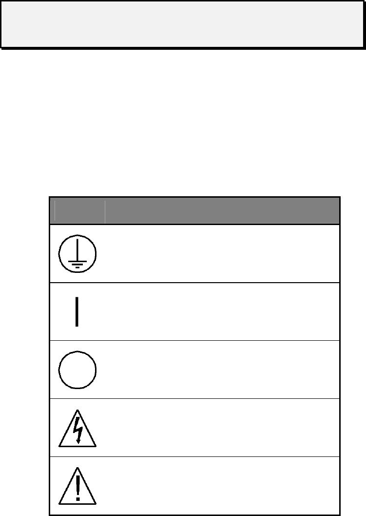
Symbols
The following table provides descriptions for the symbols that appear on the XMP
2600:
Symbol Description
Protective conductor terminal
On
Off
Caution, risk of electric shock
Warning (refer to accompanying documents)
XMP 2600 Programming Manual rev. 1.1 e
Input Mains
Voltage
Rating
The XMP 2600 operates at the following mains nominal voltages:
• 170Vac - 265Vac nominal (45 to 66Hz)
• 120Vac nominal, up to 1KW output power (45 to 66Hz)
Do not exceed this voltage range (nominal), as deterioration of performance or
damage to the unit is likely to occur. The following table shows the mains voltage
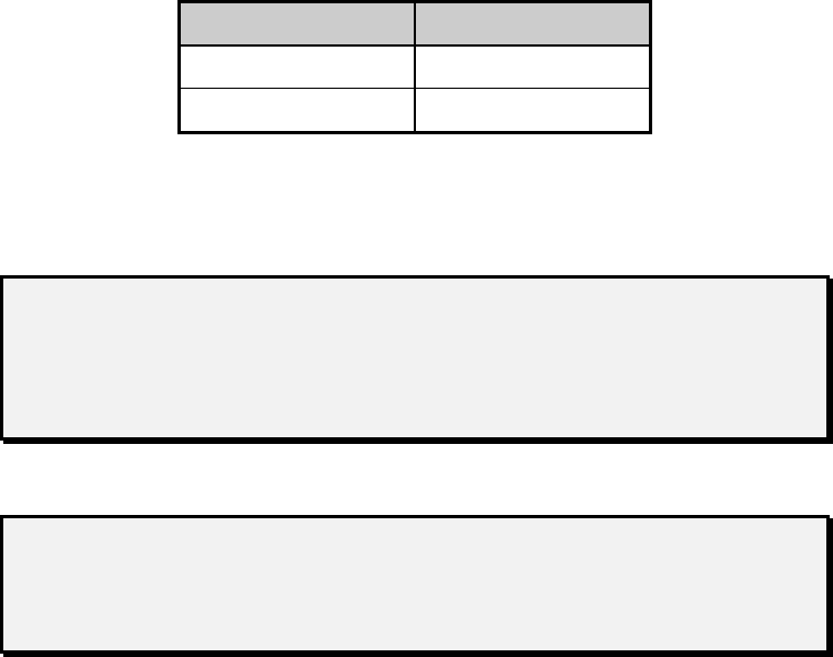
specification of the Power Supply:
Nominal Mains Nominal Current
230Vac Iin<15A
120Vac, Po<1KW Iin<15A
Mains supply voltage fluctuations may not exceed +/-10% of the nominal voltage.
Power plug shall be fitted according to each national electrical code, and rated for a
current of at least 20A.
WARNING
The XMP 2600 must be operated at the proper mains voltage. Before operating
the unit make sure the mains voltage complies with the range described above.
Noncompliance with the input voltage may cause hazard and damage to the unit!
Do Not Open
The Unit
The user, except when replacing modules, should not open the unit.
WARNING
Make sure the power cord is disconnected from the mains before opening the
unit. High voltages inside the unit may cause electric shock.
Air Inlets And
Air Outlet
The Power Supply is a forced air-cooled unit. Cooling is essential for the unit's
proper operation.
The unit includes four air inlet openings located in the front panel, in both the left
and right sides near the front panel and in the top cover near the front panel. The air
outlet is in the rear panel (all over its surface).
Make sure there are no obstructions for the airflow, at least two centimeters (0.8”)
away from these openings.
Obstructing these ventilation openings may cause fire and irreversible damage to the
unit.
Output
Voltages
The Power Supply's outputs (at the unit's rear) may carry high voltages. Make sure
to handle them properly to avoid shock hazard.
Unused outputs must be closed with load connectors (these connectors must include
sense lines connections).
Nonoperative
Modules
Do not operate the unit if it contains damaged or defective modules. Hazard or
damage may occur.
Damaged or defective units should be repaired by authorized personnel only.
f XMP 2600 Programming Manual rev. 1.1

WARNING
Do not operate the unit with a missing module. Modules must be arranged
consecutively from left to right. Unused module locations must be closed with
ventilation obstructions. Operating the unit with missing modules or missing
internal ventilation obstructions may cause overheating and fire hazard.
Power Supply
Safety WARNING — High Energy and High Voltage
Exercise caution when using and calibrating a power supply. High energy levels can
be stored at the output voltage terminals on a power supply in normal operation. In
addition, potentially lethal voltages exist in the power circuit and on the output and
sense connectors of a power supply with a rated output greater than 40 V. Filter
capacitors store potentially dangerous energy for some time after power is removed.
CAUTION
Operate the power supply in an environment free of flammable gases or fumes. To
ensure that the power supply’s safety features are not compromised, use the power
supply as specified in this manual and do not substitute parts or make any
unauthorized modifications. Contact the service technician for service and repair
help. Repairs must be made by experienced service technicians only
Regulatory Approvals and Safety Agency
Compliance
Regulatory
Approvals
European Standards: Electromagnetic Emissions and Immunity -meets Council
Directive 89/336/EEC
Electromagnetic Emissions: EN61326:1997 +A1:1998
EN61000-3-2:2000
EN61000-3-3:1995
Electromagnetic Immunity: EC61326:1997 +A1:1998
Safety
Agency
Compliance
European Standards:
Safety Meets EN61010 –1
American Standards:
Electromagnetic Emissions Meets FCC Class A
Safety Meets UL61010-1
XMP 2600 Programming Manual rev. 1.1 g
About this manual
This programming manual contains information on programming the XMP 2600.
Who should
use this
manual
This manual is designed for users who understand basic electrical theory, especially
as applied to the operation of power supplies. This implies a recognition of constant
voltage and constant current operating modes and the control of input and output
power, as well as the observance of safe techniques while making connections to the
supply and any changes in settings.
Chapters Chapter 1: Interfacing the XMP 2600 describes the hardware and software basics
of connecting a remote controller (usually a PC) to the XMP 2600.
Chapter 2: Usage Guidelines explains the recommended methods of
communicating with the XMP 2600, setting it up and using it.
Chapter 3: Basic Programming describes the way to utilize the basic features of
the XMP 2600 power supply system.
Chapter 4: Advanced Features describes the advanced features of the XMP 2600
and the way to utilize those features.
Chapter 5: Commands and Queries Reference contains a full reference of the
available commands and queries you use for controlling the XMP 2600. A list of
commands and queries, divided by category, is also provided to help you find the
right command or query to use.
Chapter 6: Status Reporting describes the status structures maintained by the
XMP 2600 and the way to manipulate and use them. A list of possible error codes is
also included.
Terminology The following explains the jargon unique to the XMP 2600 as used in this
programming manual:
Slot ................................. a physical location within the XMP’s mainframe
where power modules are installed. Each power
module occupies 1, 2 or 3 slots depending on its
voltage and current ratings.
Channel .......................... a logical location on the internal communications
link (connecting power modules to the XMP’s
main controller). Each location is identified by
an address in the range 1 to 16.
Module’s address............ the number of the channel the power module is
associated with. The power module address is
used to identify the power module in
programmed commands and other operations.
net................................... a communications link connecting power
modules to the XMP’s main controller. The net
comes in two flavors: internal net – running
inside the mainframe and external net –
interconnecting mainframes.
h XMP 2600 Programming Manual rev. 1.1

Table of Contents
Table of contents
Chapter 1: Interfacing the XMP 2600 1
The GPIB interface 1
The serial interface 2
Serial Interface Capabilities 2
Computer Versus Terminal Operation 2
Programming messages formats 3
Listening Formats 3
Talking Formats 4
Chapter 2: Usage Guidelines 5
How to communicate with the XMP 2600 5
Using the comm. channels 5
Using the GPIB bus 5
Using an RS232 link 5
Recovering from communication halts 6
The XMP’s input and output queues 6
Communicate with the XMP 2600 6
Using queries 6
Using commands 6
Programming the XMP 2600 6
Recommendations on using the XMP 2600 7
Initialize the XMP 2600 7
Identify the XMP 2600 8
Enforce power-on conditions 8
Setup the XMP 2600 status system 8
Query installed Power Modules 8
Setup system level protection shutdown features 9
Initial setup of the Power Modules 9
Activation 10
On-going usage of the XMP 2600 11
Use queries 11
Using advanced features 11
A focus on status 11
Handling SRQ and the IEEE488.2 Status Structures 11
Definitions of structural elements 12
Status registers 12
Event registers 12
Event enable registers 12
Mask registers 12
Responding to SRQ events 13
The (main) status byte 13
Main controller events 13
Output message Queue 13
Remote communication time out 14
XMP 2600 Programming Manual rev. 1.1 i

Table of Contents
Primary engine status structure 14
Summary of power modules status 14
Power modules status structure 14
What happens when power is turned on 15
Chapter 3: Basic Programming 17
Basic setup and usage 17
Output Setup 17
Overview of output setup parameters 18
Power Module output rating 18
Output program limits 18
Output protection 18
Output settings 19
Output control 19
Output activation 19
Polarity and disconnect relays 20
Current limiting schemes 20
Voltage / current mode 20
Foldback 20
Retry 21
Shutdown on current limit 21
Reprogramming Delay 21
Chapter 4: Advanced Features 23
Workpoint window warning 23
Usage guidelines 23
Using the warnings 24
Checking the status 24
Using the events mechanism 24
Additional usages 25
Load protection 25
OVP and OCP 25
Current limitation 25
Protection using the workpoint window 25
Arm, trigger, sync and ramp 26
ARM 26
The trigger mechanism 26
The SYNC output 27
Output ramping 28
What is output ramping? 28
Output ramping setup 29
Output ramping initiation 29
Synchronization of operations 29
Simultaneous operations 29
j XMP 2600 Programming Manual rev. 1.1

Table of Contents
Output on/off 30
Other operations 30
Sequential Operations 30
Using hardware (TRIG and SYNC) to serialize operations 30
Using software (OPC mechanism) to serialize operations 31
Controller notification of Operation Complete 31
Selective shutdown 32
Shutdown grouping: single, group, global 32
The different shutdown grouping of modules 32
The commands to program shutdown grouping 32
Shutdown on non-fault events 33
Comm. time out 33
Responding to communication time out events 33
Turn-on and reset behavior 34
Time out events as reflected in the status structure 34
Chapter 5: Commands and Queries Reference 35
Categories 35
IEEE 488.1 BUS Commands 35
System Commands and Queries 35
Settings Commands and Queries 37
Output Control Commands and Queries 37
Protection Commands and Queries 37
Warnings Commands and Queries 38
Read-Back Queries 38
Trigger and Sync Commands and Queries 38
Status Reporting Commands and Queries 39
Synch. Commands and Queries 39
Alphabetical reference 40
Chapter 6: Status reporting 69
IEEE 488.2 compatible Status Structures 69
Power Modules Status Structure 69
The Events Register 69
The Warnings Register 69
The Output Register 70
The Faults Register 70
The Status Register 70
The Error Code 70
The Events Enable Register 70
The Events Filtering Positive Mask Register 71
The Events Filtering Negative Mask Register 71
Power Modules Summary Register - read with SRQS? 72
XMP 2600 System Status Structure 72
Standard Event Status Register - read with *ESR? 72
Standard Event Status Enable Register - set with *ESE read with *ESE? 73
Primary Status Register - read with PSR? 73
Primary Event Status Register - read with PER? 73
XMP 2600 Programming Manual rev. 1.1 k
Table of Contents
Primary Event Status Enable Register - set with PEE, read with PEE? 73
Status Byte Register - read with *STB? 74
Service Request Enable Register - set with *SRE, read with *SRE? 74
Parallel Poll Enable Register - set with *PRE, read with *PRE? 74
Self Test Results 75
Power Modules 75
BYTE 1 76
BYTE 2 76
Main Controller 76
Error Codes summary 77
Power Modules 77
Errors Reported by the Power Module 77
Errors Detected by the Main Controller 77
Main Controller 77
Power Modules Communications errors 77
RS232 Communications errors 78
GPIB Communications errors 78
Parser and Execution errors 78
l XMP 2600 Programming Manual rev. 1.1

Interfacing the XMP 2600 The GPIB interface
1Interfacing the
XMP 2600
The XMP 2600 has two types of interfaces used for remotely controlling it: a GPIB
(IEEE 488) Interface and a Serial (RS232) Interface. The two interfaces differ only in the
communication hardware and protocol. Input and Output Queues, Command and Query
Parsing and Execution are identical no matter which interface is being used to remotely
control the XMP 2600.
The XMP 2600 has two remote controlling modes. Unless otherwise required, the IEEE
488.2 compatible mode should be used. The controlling mode in effect is DIP-Switch
selected (at the rear panel – please refer to the user’s guide) and may be overridden by a
Remote command.
The GPIB interface
The GPIB Interface is an IEEE 488.1 hardware interface with IEEE 488.2 capabilities.
The capabilities of the GPIB Interface are summarized below:
SH1 ........................ Source handshake - FULL.
AH1 ....................... Acceptor handshake - FULL.
T6........................... Talker - basic, serial poll, unaddressed if MLA.
L3........................... Listener - basic, listen only, unaddressed if MTA.
SR1 ........................ Service request - FULL.
RL1 ........................ Remote local - FULL.
PP1/PP2 ................. Parallel poll - remote and local configuration.
DC1........................ Device clear - FULL.
DT1........................Device trigger - FULL.
The size of the Input and Output Queues is 256 Bytes.
The XMP 2600 uses an Input Queue rather than an Input Buffer (as
required by IEEE 488.2). This enhancement practically prevents Lock-
Ups.
XMP 2600 Programming Manual rev. 1.1 1

The serial interface Interfacing the XMP 2600
The serial interface
The Serial Interface is RS232 hardware interface with three types of operating modes: Monitor
Mode, Remote Terminal Control Mode and Remote Computer Control Mode.
Pressing the terminal’s ENTER key while the Serial Interface is in
Monitor Mode and the GPIB Interface is OFF will cause the Serial
Interface to switch to the Remote Terminal Control Mode.
Serial
Interface
Capabilities
In addition to the Transmit and Receive lines, the interface implements the following
hardware handshake lines:
DTR - .................Data Terminal Ready.
CTS - .................Clear To Send.
RTS -..................Request To Send.
DCD - ................Data Carrier Detected.
The interface has the following programmable parameters:
Baud Rate - ........2400, 4800, 9600.
Xon/Xoff - .......Yes, No.
Stop Bits - .........1 or 2 depending on the Parity settings.
Parity - .............Odd, Even, None.
Echo - ...............Yes, No.
The number of Start Bits is fixed at 1.
The Serial Interface Parameters are set in the SERIAL SET-UP MODE (see: User’s
Guide).
The Serial Interface always uses “hardware handshake” (signals CTS and
RTS). If you do not wish to utilize those signals, short pins 7 and 8 of the
connecting cable, on the XMP’s side (see the User’s Guide for further
details).
Computer
Versus
Terminal
Operation
The selection of the ECHO parameter determines the Remote Control Mode of operation
by changing some aspects of the behavior of the Serial Interface, as detailed below:
echo Yes (terminal) No (computer)
echo echo each received character no echo
prompt '>' {ACK}
SRQ string '{bell}SRQ<' 'SRQ<'
terminators {CR} echoed as {CR}{LF} {CR}{LF} or {LF}
In the Computer Remote Control mode of operation, the XMP 2600 will respond to each
command string with an ASCII {ACK} - 06 HEX.
2 XMP 2600 Programming Manual rev. 1.1
Interfacing the XMP 2600 Programming messages formats
Programming messages formats
Listening
Formats
Programming messages received by the XMP 2600 are comprised of the following
elements:
Program Message.......................... a programming command, query or data sent to the
XMP 2600 from the Controller. A Program Message
may have zero or more of the following:
Program Message Unit .. the actual command or query (including data) sent to
the XMP 2600 by the Controller. A Program Message
Unit is either a Command Message Unit or a Query
Message Unit. The Program Message Unit is made
out of the following elements:
Command Program Header or Query Program Header
............................. the Program Header represents the operation to be
performed by the XMP 2600. A Query Program
Header is always ended with a “?”. Headers can be in
Lower or Upper Case letters.
Program Header Separator separates the Program Header
from the Program Data elements. It is the ASCII
character <white space>.
Program Data ...... zero or more Program Data elements separated by a
Program Data Separator may be included in the
Message Unit (as required by the specific Program
Header). A Program Data element may be one of the
following:
<ch> ............ Channel Number is a decimal number in the range 1
to 16.
<value> ....... a Decimal Value expressed either in implicit or
explicit point format. In some cases a sign (“+” or “-”)
may precede it.
<int>............ a Decimal Integer Value.
<string>....... a series of ASCII characters enclosed within a pair of
a specific character.
Program Data Separator separates Program Data elements. It is
the ASCII character “,” and may have any number of
<white space> characters surrounding it.
Program Message Unit Separator separates Program Message Units
contained within a single Program Message. The
Separator is the ASCII character “;” and may have
any number of <white space> characters surrounding
it.
Program Message Terminator ...... terminates the Program Message. Together they form
a complete transmission. The Terminator may be one
of the following:
<LF> or <NL>.............. Line Feed or New Line (ASCII code 10).
<CR><LF> ................... Carriage Return & Line Feed (ASCII codes 13 & 10).
<EOI>............................ the GPIB single line EOI message. It may be
combined with a <LF> ASCII code byte.
XMP 2600 Programming Manual rev. 1.1 3
Programming messages formats Interfacing the XMP 2600
Here is an example of a Program Message:
VSET 1,10.2 ; VLOAD? 1 <LF>
Program
Message
Terminator
<ch>
Program
Unit
Message
Separator
Query
Program
Header
Command
Program
Header
<ch>
Program
Data
Separator
<value>
Talking
Formats
Response Messages sent by the XMP 2600 are comprised of the following elements:
Response Message ......................... a message sent by the XMP 2600 in response to a
Query received from the Controller. The Response
Message is made out of the following elements:
Response Data...... one or more Response Data elements separated by a
Response Data Separator may be included in the
Response Message (as required by the specific Query
that generated that Response). A Response Data
element may be one of the following:
<value> ....... a Decimal Value expressed either in implicit or
explicit point format. In some cases a sign (“+” or “-”)
may precede it.
<int>............ a Decimal Integer Value 0 to 255.
<string>....... a series of ASCII characters.
Response Data Separator separates Response Data
elements. It is the ASCII character “,” and may have
<white space> characters surrounding it.
Response Message Terminator terminates the Response Message.
Together they form a complete transmission. The
Terminator is <CR><LF> (Carriage Return and Line
Feed ASCII codes 13 and 10). For GPIB the <LF>
character will have <EOI> asserted.
4 XMP 2600 Programming Manual rev. 1.1
Usage Guidelines How to communicate with the XMP 2600
2Usage Guidelines
How to communicate with the XMP 2600
The purpose of this section is to give the user of the XMP 2600 power system basic
guidelines on how to communicate with the Power Supply.
Communicating with the XMP 2600 involves proper usage of the communication
channels (either GPIB or RS232), understanding how the XMP 2600 handles the
communication from/to the controlling computer and learning the recommended way to
communicate with the XMP 2600.
The following sections will tackle the aforementioned issues, in detail.
Using the
comm.
channels
To communicate with the XMP 2600 one can use either the GPIB bus or an RS232 link.
Beyond the basic differences between the two communication mediums (not covered in
this manual) both provide the user of the XMP 2600 full access to the XMP’s features.
The only advantage of the GPIB bus (beyond its hardware characteristics) is the ability to
send bus commands, such as DCL (Device Clear).
Using the GPIB bus
There are several options for terminators to use when communicating with the XMP
2600:
1. EOI
2. LF (or CRLF)
3. LF + EOI
We recommend the use of LF (without EOI).
Do not use the “auto serial poll” feature of some GPIB drivers. If you want to use SRQs,
do the serial poll (or use the *STB? Query) in your program.
Using an RS232 link
RS232 is an asynchronous communication link. The XMP 2600 uses a software method
to synchronize communication with it: for every command or query message (ending
with a LF or CRLF) that you send to the XMP 2600 it will reply with the ASCII character
ACK (acknowledge) – 6 Hex.
This method provides assurance that the communication link is working properly and
serves the function of the handshake lines of the GPIB bus.
XMP 2600 Programming Manual rev. 1.1 5
How to communicate with the XMP 2600 Usage Guidelines
To use this synchronization feature properly, you must follow each message sent to the
XMP 2600 with a read operation, reading one character and verifying its value (6).
Recovering from communication halts
If, for some reason, communication with the XMP 2600 halts, use one of the following
methods to clear the XMP’s input and output queues and reestablish communication:
1. Press the front panel LOCAL button.
2. Send a GPIB bus DCL (Device Clear) multi-line command.
3. Reset the XMP 2600 using the front panel buttons DEL & LOCAL.
4. Reset the XMP 2600 using the hardware command (on/off) connector at its rear.
5. Reset the XMP 2600 by cycling its power.
The XMP’s
input and
output
queues
The XMP 2600 uses two queues (256 bytes long, each) for holding input (data you send
to the XMP) and output (replies you should read from the XMP).
You must make sure not to fill those queues up or communication with the XMP 2600
may, in some situations, fail.
Communicate
with the XMP
2600
The following paragraphs elaborate on the proper usage of commands and queries while
communicating with the XMP 2600.
Using queries
When using queries (questions) with the XMP 2600, you must make sure that for each
query that you send to the XMP 2600, you read the reply the XMP 2600 has placed in its
output queue.
Although it is possible to send several queries and then read all the replies (you will need
a separate read for each reply), it is a better practice to send a single query and read its
reply before sending another query.
If for some reason you find out that the reply you are reading is not for the query you
have sent (lost of synchronization between replies and queries) send the BUFCLR
command or use one of the procedures depicted above at “recovering from
communication halts”. This operation will clear both the input and the output queues of
the XMP 2600 and resynchronize queries with replies.
Using commands
The XMP 2600 stores the commands (and queries) that you send to it in its input queue
until it is ready to parse and execute them.
Parsing and executing the commands and queries is done when the XMP 2600 is not busy
communicating with its Power Modules.
This means that command execution might be held of for as long as a second (usually
commands are executed within 200mS).
If you send many commands with short intervals between them, sometimes you may get
into a situation where the XMP’s input queue will fill up due to commands waiting for
execution. This might lead to a communication halt.
Programming the XMP 2600
Bearing in mind all of the above, you should follow the guidelines in the following
paragraphs:
6 XMP 2600 Programming Manual rev. 1.1
Usage Guidelines Recommendations on using the XMP 2600
Starting a session
Issue a CLR or RESET command (and wait for 15 seconds) when you start using the
XMP 2600.
This will ensure that the XMP 2600 is in a known state, ready for you to program it.
When queries are not used
If you do not use queries often (see bellow) in your program, send commands in small
groups (no more than 4 per second). Use delays to spread commands over time, if
necessary.
This way you can make sure you will not fill up the input queue of the XMP 2600.
Use queries
Following each group of commands, send a query and read its reply.
This procedure will make sure that the commands in the input queue were executed
(because the query was last in the queue) and the queue is empty.
It is a good practice to send status queries (*STB?) every now and then to make sure the
XMP 2600 has no errors or faults to report. Following each *STB? query, you may need
to send more status queries, depending on the reply of the XMP 2600 (see the Handling
SRQ and the IEEE488.2 Status Structures section for more details).
It is, also, a good idea to read the output voltage of each Power Module, following the
setup stage of your program. This way you can be sure that the XMP 2600 is outputting
the voltages you have requested.
If you follow each group of commands, sent to the XMP 2600, with a query (and read the
reply to the query) you may freely send commands as fast as the XMP 2600 is ready to
receive them.
A focus on status
Following every major operation with the XMP 2600 (such as changing output values,
turning a Power Module on or off, etc.), read its status (or use SRQ to be interrupted
when errors or faults occur).
Reading the status of the XMP 2600 often, ensures communication synchronization.
Recommendations on using the XMP 2600
The purpose of this section is to give the user of the XMP 2600 power system basic
guidelines on how to use the XMP 2600.
Using the XMP 2600 power system is divided into two tasks: initialization and on-going
usage.
The following sections will engage in giving the user of the XMP 2600 an understanding
of the recommended way to achieve those two tasks.
Initialize the
XMP 2600
When working with a device rich in features, like the XMP 2600, it is essential for the
user to know exactly what state the device is in and how it is setup.
Going through an ordered initialization phase can assure the user of the XMP 2600 that
the power system is setup exactly like he wanted it to be.
XMP 2600 Programming Manual rev. 1.1 7
Recommendations on using the XMP 2600 Usage Guidelines
Identify the XMP 2600
Using the *IDN? query, it is possible to verify that the device you are communicating
with is indeed a XMP 2600 power system.
The *IDN? query also returns the firmware revision code for the XMP’s main controller.
Use the GPIB? query to make sure the XMP 2600 is operating in IEEE488.2 mode.
Enforce power-on conditions
Power-on retain
Using the XMP 2600 in a computer controlled environment eliminates the need to use the
Power On Retain feature because the controlling computer can easily re-program the
XMP 2600 to a required state.
Therefore, set the Power On Retain feature to OFF (or NO). This can be done manually
(using the front panel, in setup mode) or using the POR command. The XMP 2600 will
remember your selection when it is turned off.
Clear / Retain Event Enable Registers
Similar to the Power On Retain issue, it is better to let the XMP 2600 clear the Event
Enable Registers at power-on.
Clearing the Event Enable Registers is the default behavior of the XMP 2600 at power-
on. Using the *PSC command, the XMP 2600 can be instructed to the behavior suitable
for the user.
Use a CLR or RESET command
Use either the CLR (clear) or the RESET command to force the XMP 2600 to its initial
conditions.
The RESET command will set the XMP 2600 to the exact state it would be in following
turn-on.
The CLR command is similar to the RESET command with the following differences:
It will take the minimum number of actions necessary to set the XMP 2600
to its turn-on state. In contrast to the RESET command, Power Modules
will not be reset if not necessary for clearing malfunctions.
The XMP 2600 main status structure is not cleared.
Following a CLR or RESET command you should wait for 15 seconds before attempting
to communicate with the XMP 2600.
Setup the XMP 2600 status system
Before dealing with the Power Modules and to complete the XMP 2600 power system
initialization, you should setup the mask registers of the XMP’s main controller status
structure.
Use commands like *ESE, *PRE, *SRE and PEE to setup the XMP’s event and SRQ
generation masks.
Query installed Power Modules
Before using the XMP 2600 power system, it is a good practice to make sure that the
system contains the Power Modules that you expect it to have.
8 XMP 2600 Programming Manual rev. 1.1
Usage Guidelines Recommendations on using the XMP 2600
Check occupied channels
Power Modules of the XMP 2600 have addresses that assign them to “channels” (or
“slots”).
Use the CHNL? query to find out which channels are occupied by Power Modules.
Check installed Power Modules
Once you know what channels are occupied, your next step is to verify that those
channels are assigned the correct Power Modules.
For each occupied channel, use the VMAX?, IMAX?, IMIN? and OPT? queries to learn
the following:
Output voltage rating of the Power Module.
Output current rating of the Power Module.
Minimal allowed value for current limit (or current set) programming of the
Power Module.
Installed options, like: output disconnect relays, polarity relays and type of
disconnect relays.
You may also use the SN? query to get the Power Module’s serial number, for further
identification.
Setup system level protection shutdown features
The XMP 2600 has many protection features geared at protecting the connected loads.
Some protection features have programmable system wide effect you should consider and
setup.
Reaction to Power Modules events
Use the CESE command to inform the XMP 2600 of the Power Modules whose events
you would like it to respond to.
Using commands like GLBL, GRP and SHUT you control the way the XMP 2600 reacts
to Power Modules faults and warnings.
Handling controller communications drops
The controller communications monitor function of the XMP 2600 give you the
confidence that the loads connected to the power system are protected even when
communication with the controlling computer is halted.
Use the TOGRP, TOSET and TOEN commands to setup this feature, when you intend to
use it.
Initial setup of the Power Modules
Following global setup of the XMP 2600 power system, you are now ready to setup
individual Power Modules.
The process of setting up a Power Module deals with three issues: protection features,
output settings and status reporting.
Note that most programmable features have default values (or states) that are suitable for
most applications, thus simplifying the setup process.
XMP 2600 Programming Manual rev. 1.1 9
Recommendations on using the XMP 2600 Usage Guidelines
Protection setup
Use the PROT command to setup the way Over Voltage and Over Current protection
values are assigned (automatically or manually).
If you have decided to use manual protection settings, use the OVSET and OCSET
commands to setup the desired protection values.
Select the Foldback scheme you wish to use (FOLD command) and the amount of
reprogramming delay you wish to apply (DLY command).
If you wish to use the window feature of the XMP 2600 (in order to receive warnings or
employ an Under Voltage or Under Current protection mechanism) enable the proper
window level thresholds using the WHIGH and WLOW commands.
Use the POLEN command to enable the XMP 2600 to process negative voltage setting
values.
Output settings
Setup the desired output values (VSET and ISET commands) and, optionally, the window
thresholds (VLOW, VHIGH, ILOW and IHIGH).
Remember that high window values can only be programmed to values above the
appropriate set values. Thus, for example, if you wish to use a window high current
threshold value lower than the limiting output value (ISET) you should program ISET to
the expected value, setup the ILOW and IHIGH values and then raise ISET to the limit
value.
Set the desired initial state of the output disconnect (DISC command) and polarity (POL
command) relays.
If the hardware SYNC signal is going to be used, use the SYNC command to tell the
Power Module when to generate a SYNC signal.
Setup the Power Module’s reaction to a hardware or software trigger, using the TRIG
command.
Status reporting
If so desired, use the CMASK command to setup each Power Module’s event filtering
mechanism. This mechanism enables you to limit the type of events reported by the
Power Modules to the XMP’s main controller.
Activation
Once everything is setup properly, you are ready to activate the outputs of the XMP 2600.
Output on
For a Power Module’s output to be active, the following conditions must be met:
The Main Converter is operating. •
•
•
•
•
The XMP 2600 is globally “turned on”.
The Power Module is turned on.
The Power Module does not report any fault.
The output disconnect relay is closed.
To control the output of an individual Power Module, use the OUT command with the
module’s number as a parameter.
10 XMP 2600 Programming Manual rev. 1.1
Usage Guidelines Handling SRQ and the IEEE488.2 Status Structures
To globally control the outputs of all the Power Modules, use the OUT command with no
module number.
Verification
Read the output voltage and/or current of the activated Power Modules. Use the VOUT?
(measured at the output connector), VLOAD? (measured at the sense lines) and IOUT?
queries to verify proper operation. Allow at least a second from the output activation to
the time you read back the output’s actual values.
On-going
usage of the
XMP 2600
The XMP 2600 uses two queues (256 bytes long, each) for holding input (data you send
to the XMP) and output (replies you should read from the XMP).
You must make sure not to fill those queues up or communication with the XMP may, in
some situations, fail. For further details, please refer to the previous section.
Use queries
Following each group of commands, send a query and read its reply.
This procedure will ensure that the commands in the input queue have been executed
(because the query was last in the buffer) and the queue is empty.
It is a good practice to send status queries (such as *STB?) every now and then to make
sure the XMP 2600 has no errors or faults to report. Following each *STB? query, you
may need to send more status queries, depending on the reply of the XMP 2600 (see the
Handling SRQ and the IEEE488.2 Status Structures section for more details).
If you follow each group of commands, sent to the XMP 2600, with a query (and read the
reply to the query) you may freely send commands as fast as the XMP 2600 is ready to
process them.
Using advanced features
Consult the Advanced Features chapter of the programming manual and other application
notes on how to use the advanced features of the XMP 2600.
A focus on status
Following every major operation with the XMP 2600 (such as changing output values,
turning a Power Module on or off, etc.), read its status (or use SRQ to be interrupted
when errors or faults occurs).
Reading the status of the XMP 2600 often, ensures communication synchronization
Handling SRQ and the IEEE488.2 Status Structures
The purpose of this section is to clarify the usage of the XMP’s Status Structures, explain
how to set it up and how to respond to SRQ’s.
The Status Structures of the XMP 2600 follow the guidelines of the IEEE488.2 standard.
The Status Structures are based on a “tree” formation: the “leaves” are the detailed status
information and the branches summarize that information down to a single bit of
information.
A graphical depiction of the formation of the Status Structures is shown in the Status
Reporting chapter (chapter 6).
XMP 2600 Programming Manual rev. 1.1 11

Handling SRQ and the IEEE488.2 Status Structures Usage Guidelines
The status reporting mechanisms of the XMP 2600 are rather complex. If
you do not intend to use the advanced warnings and protection features of
the XMP 2600 you may choose to disregard most of the reported status
with the exception of the main status byte and the error code registers.
Definitions of
structural
elements
We will start this discussion with a short explanation of the various elements comprising
the Status Structures.
Status registers
The status registers are collections of bits (usually 8) that depict the current state of
elements within the XMP 2600 system. Each bit reflects the actual state of a feature or
sub-assembly. When the state of the feature or sub-assembly changes so does the value of
the status bit.
For example, lets look at the STBY bit (bit 0) of the Output Status Register of a Power
Module. This bit will always reflect the state of the output of the Power Module: when
the Power Module’s output is in standby (i.e. the output is disabled and no voltage is
coming out of its connector) the bit value will be 1. When the Power Module’s output is
enabled, the bit value will be 0.
Event registers
Event registers indicate changes in the status of features or sub-assemblies. Note that in
contrast to the status registers, event bits remain set (having a value of 1) even if the
status changes back. The event indication will be cleared when the controlling computer
reads the event register.
For example, the FLT bit (bit 2) of the Event Register of a Power Module will be set
when a fault occurs (individual faults are indicated by the bits of the Faults Register).
When the fault condition is removed (e.g. an Over Temperature condition is no longer
valid) the corresponding Faults Register bit will be cleared but the FLT bit of the Event
Register will remain set.
When the computer reads the Event Register, the FLT bit is cleared even if the actual
fault condition is still true (as will be depicted by the Faults Register). The FLT bit will
be set again when a new fault condition occurs.
Event enable registers
As mentioned in the introduction, each status structure is summarized to a single bit that
is then used in the next level of status (or event) registers.
The Event Enable Register determines the way data is being summarized. The process is
fairly simple: the Event Register is ANDed with the Event Enable Register and if the
result has any set bits then the summary bit is set.
Mask registers
Some of the Status Structures of the XMP 2600 include (fixed or programmable) Mask
Registers. These registers determine which status changes will be registered as events.
For example, only positive Primary Status changes (i.e. a change from non-existing to
existing) are recorded in the Primary Event Register.
The Status Structure of the Power Modules include a programmable event filtering
mechanism that enables filtering of either positive or negative transitions of warning
conditions.
12 XMP 2600 Programming Manual rev. 1.1
Usage Guidelines Handling SRQ and the IEEE488.2 Status Structures
Responding
to SRQ
events
The SRQ event of the IEEE488.2 bus is the summary of the entire Status Structure of the
XMP 2600.
The following paragraphs will show how to traverse the Status Structure tree in order to
find the cause of the generated SRQ.
This explanation will, also, show how to setup the programmable elements of Status
Structure in order to be notified only on events of interest.
The (main) status byte
The SRQ event is generated in response to bits of the Status Byte being set (a positive
transition).
Each time a bit of the Status Byte is being set (changing from 0 to 1) the Status Byte is
being ANDed with the Service Request Enable Register. If the result of the AND
operation has any bits set to 1 – an SRQ will be generated. In other words – the SRQ
event (or flag) is the summary of the Status Byte and the Service Request Enable Register
is the “Event Enable Register”.
Thus, the first response to an SRQ event is to read the Status Byte. This can be achieved
in two fashions: performing a serial poll or issuing the *STB? Query.
Once we have got the value of the Status Byte, we can investigate the cause of the SRQ
event.
The Status Byte summarizes the following Status Structures:
ESB - XMP’s main controller events
MAV - Output Message Queue (Message AVailable).
COM TO – Remote Communications Time Out.
PRIM ERR - XMP’s Primary Engine (main converter) faults.
SRQ IS - Power Modules.
Whenever one of these bits is set, the corresponding higher level of the Status Structure
should be probed.
Main controller events
This part of the Status Structure is made out of an Event Register and its corresponding
Event Enable Register. The summary of this pair of registers appears in the Status Byte in
the form of the ESB bit.
The main controller’s Event Register (also called the Standard Event Status Register)
holds the Power On, Error and OPC events. The register is read using the *ESR? Query.
The last known error code is read using the ERR? Query.
The OPC event (OPeration Complete) occurs when the *OPC command follows a
lengthy operation (e.g. a change in the output voltage of a Power Module – VSET
command).
The PON event occurs when the XMP 2600 is powered up.
Output message Queue
The MAV (Message AVailable) bit of the Status Register is the only element of this part
of the Status Structure.
The bit is set to 1 whenever the Output Queue holds a response to a query.
This enables the software of the controlling computer to work with the XMP 2600
asynchronously.
XMP 2600 Programming Manual rev. 1.1 13
Handling SRQ and the IEEE488.2 Status Structures Usage Guidelines
Remote communication time out
The Remote Communications Time Out bit is the only element of this part of the Status
Structure.
The bit is set to 1 when the Time Out mechanism is enabled and a Time Out event occurs.
Primary engine status structure
The Status Structure associated with the Primary Engine of the XMP 2600 is made out of
the Primary Status Register, a fixed positive Mask Register, the Primary Event Status
Register and the Primary Event Status Enable Register.
The summary bit of this Status Structure (the PRIM ERR bit) will be set when Primary
events are registered in the Primary Event Status Register and the corresponding bits of
the Primary Event Status Enable Register are set. Note that the Primary Event Status
Register records only occurrences of conditions and does not register anything when a
condition is removed (this is the work of the positive Mask Register).
If the PRIM ERR bit was read as 1, the Primary Event Status Register should be read
(using the PER? Query). This will reveal what Primary event has occurred since the
register was last read.
The actual status of the Primary Engine can be obtained using the PSR? Query.
Summary of power modules status
Each of the Power Modules in the XMP 2600 system has its own Status Structure. The
summary bits of those Status Structures are grouped in a 16-bit register (read as two 8 bit
registers) called the Power Modules Summary Register.
This register (read with the SRQS? Query) is summarized in the Status Byte as the SRQ
IS bit.
The SRQ IS bit will be set whenever one of the bits of the Power Modules Summary
Register is changed to 1.
The content of the Power Modules Summary Register is cleared when the controlling
computer reads the register.
Bits of the Power Modules Summary Register are set when Power Modules events seep
through the filters of the Power Modules Status Structures.
When the SRQ IS bit of the Status register was read as 1, the Power Modules Summary
Register should be read. For each set bit in the Power Modules Summary Register the
corresponding Power Modules Status Structure should be explored.
Power modules status structure
The Status Structure of the Power Modules is made out of the following elements:
• Status Registers – Warnings, Output state, Faults, Error Code and general
Status.
• Mask Registers – some are fixed and some are programmable.
• Event Register.
• Event Enable Register.
The summary bit of the entire structure is read at the Power Modules position in the
Power Modules Summary Register (e.g. the summary bit of module number 3 will be
evident at bit 2 of the summary register [bits are counted starting with 0]).
The Power Module Status Structure is read as a whole using the CSTS? Query.
14 XMP 2600 Programming Manual rev. 1.1
Usage Guidelines Handling SRQ and the IEEE488.2 Status Structures
The first element of the Power Module Status Structure we should look at is the Events
Register.
The Events Register
The Events Register, together with its corresponding Events Enable Register generates
the summary bit. Note that the Events Enable Register is common to all the Power
Modules.
The Events Enable Register determines which of the Power Modules Events may cause
an SRQ.
The content of the Events Register is cleared when read.
The Events Register, in turn, receives its data from the filtered status registers. The status
registers’ data is filtered using the mask registers. The following paragraphs will describe
the behavior of the status registers and their associated mask registers.
The Error Code
This register holds the last known error detected by the Power Module. The content of
this register is cleared when read.
Whenever the Power Module detects a new error, the corresponding bit of the Event
Register is set as well (a positive fixed mask).
The Faults Register
This register indicates the faults detected by the Power Module’s controller. This is a
status register (showing the current state of the Power Module) but most of the faults are
“sticky” – the fault condition remains true until a reset command is issued.
Any new fault detected by the Power Module’s controller will cause the corresponding bit
of the Events Register to be set (a positive fixed mask). The exception to this rule is the
Sense Warning condition, which is depicted in the Faults Register but is filtered the same
way that warning events are (see bellow).
The Output Register
This status register depicts the current state of the Power Module’s output circuitry.
Any change in the Output status register will cause the corresponding bit of the Events
Register to be set (no masking).
The Warnings Register
This status register indicates warning conditions. As it is a status register, it will indicate
the current true state of the warnings.
Using the programmable mask registers (both positive and negative masks) the conditions
that will cause the WRN bit of the Events Register to be set can be determined.
These mask registers are individual to each Power Module and enable a very flexible
setup. A description of this feature is included in the Status Reporting chapter of the
Programming Manual.
What
happens
when power
is turned on
An IEEE488.2 defined command (*PSC) determines what will the XMP 2600 do with the
event enable registers when turned on.
The *PSC command may enable the XMP 2600 to clear all the events enable registers
and the SRQ Enable Register.
This feature ensures that the XMP 2600 wakes up with a known state. It also ensures that
the XMP 2600 will not generate undesirable SRQ’s at power on.
XMP 2600 Programming Manual rev. 1.1 15
Handling SRQ and the IEEE488.2 Status Structures Usage Guidelines
The Power On Retain or Initialize feature is another powerful tool for controlling the turn
on behavior of the XMP 2600.
16 XMP 2600 Programming Manual rev. 1.1
Basic Programming Basic setup and usage
3Basic Programming
This chapter guides you through the process of programming the XMP 2600 to provide
power at the outputs of its Power Modules.
Basic setup and usage
Assuming the XMP 2600 is initialized at turn-on (or no advanced features were used
before) it is possible to rely on the default setup of the XMP 2600 and use a very small
and basic set of commands.
Using the VSET and ISET commands you can program each Power Module to provide
the required output voltage and current. The commands to use have the form:
VSET <ch>,<value> (e.g. VSET 1,12.44 to set channel 1 to provide 12.44V)
and
ISET <ch>,<value> (e.g. ISET 1,5 to set channel 1 to a current limit of 5A).
For the Power Modules’ outputs to be turned on you should issue an ON command to
each Power Module as well as a global output enable command. The commands to use
have the form:
OUT 1 (global output enable)
And
OUT <ch>,1 (to turn on the individual Power Module)
To turn off the outputs of the XMP 2600 use one of the following methods:
1. Turn off all the outputs using the global output disable command: OUT 0.
2. Turn off individual Power Modules using the command: OUT <ch>,0.
This basic setup is sufficient for a very basic usage of the XMP 2600. The XMP 2600
automatically programs the Over Voltage and Over Current protection levels (+10%) and
no other protection or warning mechanism is activated.
Output Setup
Using a very basic setup (as described above) might be sufficient for some applications
but not for all of them.
XMP 2600 Programming Manual rev. 1.1 17
Output Setup Basic Programming
The XMP 2600 has a host of features that enhance its usage. This section describes the
parameters involved in setting-up the outputs of the XMP 2600 Power Modules.
Power Module output rating
Overview of
output setup
parameters Each XMP 2600 Power Module is defined by its output rating (the amount of voltage and
current it can deliver). The user can use a Power Module up to its output rating, named
Vmax and Imax.
Output voltage can be programmed in the range 0 to Vmax and output current can be
limited to a value in the range Imin to Imax.
Vmax, Imax and Imin are the Power Module output rating – they cannot be programmed,
only read (for reference) using queries like:
program
range
Imin Imax
V
VMAX? <ch> Vmax
IMAX? <ch>
IMIN? <ch>). I
Output program limits
Some times it might be desirable to limit the maximal values that may be programmed for
the output’s voltage (Vlim) and/or current (Ilim) settings. Circumstances like this may
rise when, for example, using a 36V Power Module with a load that tolerates voltages up
to 14V only. Setting a limit on the ability to program the output voltage of a Power
Module ensure that no higher output voltages will be produced, by accident.
Placing limits on output programming (Vlim and Ilim) is achieved using the commands:
VLIM <ch>,<value>
program
range
Imin Imax
Vmax
V
and Vlim
ILIM <ch>,<value>
where <value> is limited by either Vmax or Imax and
defaulted to Vmax and Imax.
I
Ilim
Output protection
Each Power Module of the XMP 2600 has Over Voltage and Over Current protection
settings. When the output’s voltage or current exceed the protection threshold the Power
Module is shut down and a fault event is generated.
The protection thresholds may be programmed by the user (manual mode) or set
automatically by the XMP 2600 (automatic or tracking mode which is the default)
whenever a new output setting (see bellow) is programmed.
Determining the way protection values are set is done using the command:
PROT <ch>,<mode>
where <mode> can be either 0 for manual or 1 for automatic.
When using the manual protection setting mode, use the following commands to set the
protection thresholds (OVset and OCset):
OCset
range
OVset
range
Imin Imax
Vmax
V
OVSET <ch>,<value>
and Vset
OCSET <ch>,<value> I
Iset
18 XMP 2600 Programming Manual rev. 1.1

Basic Programming Output control
where <value> can be programmed between the output setting value (Vset or Iset) and the
output rating (Vmax or Imax) + 10%.
When changing the settings of an output while using a manual setting
mode for the protection thresholds, follow the guidelines shown here:
For up programming, raise the protection thresholds before you raise the
output settings.
For down programming, set the new output settings before you lower the
protection thresholds.
Output settings
Setting the desired output’s voltage and current (Vset and Iset) is done using the
following commands:
VSET <ch>,<value>
and
ISET <ch>,<value>
where <value> is limited by the lower of Vlim or OVset for voltage and Ilim or OCset for
current. Iset has a lower limiting value on its programming – Imin.
Output control
Once set up, a Power Module needs to be turned on to enable it to provide power at its
output.
A Power Module will provide power at its output when all the following conditions are
true:
The Primary (main converter) is turned on (not shutdown using the external
hardware control feature or due to a fault).
The XMP 2600 outputs are globally enabled (using the OUT 1 command).
The Power Module is not shutdown due to a fault or the selective shutdown
mechanism.
The Power Module is turned on (using the OUT <ch>,1 command).
The output disconnect relay of the Power Module is closed (default state or
use the DISC <ch>,0 command.
The following sections describe the commands available to you for controlling the
outputs of the Power Modules.
Output
activation
Activating the output of a Power Module (turning it on) is done in two levels. Please note
that at turn on, the outputs are disabled both individually and globally.
Globally enabling the outputs
Use the OUT 1 command to globally enable the outputs of all the Power Modules.
Note that only Power Modules that are individually turned on will actually have their
outputs turned on when this command is issued.
XMP 2600 Programming Manual rev. 1.1 19
Current limiting schemes Basic Programming
Issuing the OUT 0 command, globally disables the outputs of all the Power Modules.
Turning the output on or off
Use the OUT <ch>,1 command to turn on the output of a specific Power Module.
Not that only if the other conditions mentioned at the top of this section are met then the
Power Module’s output will be activated.
Use the OUT <ch>,0 command to turn off the output of a specific Power Module.
Polarity and
disconnect
relays
Each XMP 2600 Power Module has two sets of output relays: disconnect and polarity
reversal.
Disconnect relays
The output disconnect relays are operated using the DISC <ch>,<mode> command,
where <mode> can be either 1 for disconnect or 0 for connect.
Polarity reversal relays
The output polarity reversal relays are operated using the POL <ch>,<mode> command,
where <mode> can be either 1 for negative or 0 for positive.
Auto polarity
The auto-polarity programming feature allows for the output voltage settings to be
programmed as either a positive or a negative value.
When auto polarity is enabled, the polarity of the programmed Vset value automatically
controls the state of the polarity reversal relays.
While auto polarity is enabled and the polarity of the corresponding output is reversed,
voltage readback values have a minus sign preceding them.
To enable auto polarity, issue the POLEN 1 command.
To disable auto polarity, issue the POLEN 0 command.
Current limiting schemes
The Power Modules of the XMP 2600 have 5 different output current limiting schemes.
The following sections describe each of those schemes.
The output current limiting scheme is selected using the FOLD <ch>,<mode> command,
where mode can have a value between 0 and 4.
Voltage /
current mode
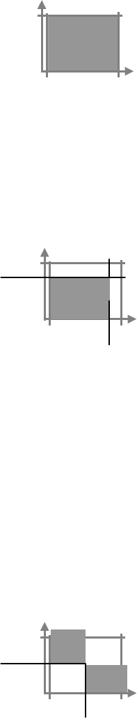
This output current limiting scheme, selected using
mode = 0 (FOLD <ch>,0), instructs the Power Module to
operate as either a voltage source or a current source with
automatic switching between the two modes of operation.
V
I
operating
range
Vset
This, default mode, is the most commonly used output
current limiting scheme. The window workpoint warning
feature can be used in combination with this output current
limiting scheme to give you a more tight control over the
load’s behavior.
Iset
Foldback Foldback is an output current limiting scheme in which both output voltage and output
current are reduced when the Power Module is operating as a current source (current
limitation is active).
There are two types of output foldback to choose from: linear and non-linear.
20 XMP 2600 Programming Manual rev. 1.1
Basic Programming Reprogramming Delay
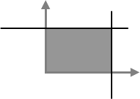
Linear foldback
When the linear output foldback mode of operation
is selected (using the FOLD <ch>,2 command),
when the output current of the Power Module
reaches its limiting value, output voltage and output
current are reduced (depending on the characteristics
of the connected load) down to 0 volts and 30% of
the set current (for an output short-circuit).
operating
range
V
Vset
I
Iset
Non-linear foldback
When the non-linear output foldback mode of
operation is selected (using the FOLD <ch>,3
command), when the output current of the Power
Module reaches its limiting value, output voltage
drops but the output current is held at its limiting
value (depending on the characteristics of the
connected load). This continues until output voltage
has dropped down to 70% of the set value. From that
point on, output voltage and output current are
reduced (depending on the characteristics of the
connected load) down to 0 volts and 30% of the set
current (for an output short-circuit).
operating
range
V
Vset
I
Iset
Retry When the retry current limiting mode of operation is
selected (using the FOLD <ch>,1 command), the output
of the Power Module will shutdown for 3 seconds when
the output current reaches its limiting value. Following the
3 seconds off time, the output of the Power Module will
be reactivated. If during the next second the output current
is still at its limiting value, the output will be shutdown
again. This process is repeated 5 times. After the
fifth consecutive shutdown, the output of the Power
Module remains shut and a fault event is generated.
fault
V
t
This operating mode is useful when the connected load can be reset (and thus the cause of
the excessive current eliminated) by removing the power that feeds it.
Shutdown on
current limit
This mode of output current limiting (selected using the FOLD <ch>,4 command) is
suitable for very sensitive loads. When this operating mode is selected, the output of the
Power Module is shutdown as soon as the output current reaches its limiting value.
Reprogramming Delay
When the output of a Power Module is changed (new set values are programmed or it is
turned on or off) some transient phenomenon might occur. These transients in the
output’s voltage or current are due to the output’s settings, output’s capacitance and the
connected load.
The transients in the Power Module’s output need to be ignored so they will not generate
warnings or faults. This is achieved by defining a period of time (called the
Reprogramming Delay period) in which the Power Module ignores transients in its
output. The Reprogramming Delay period is activated following every programmed
change in the Power Module’s output.
XMP 2600 Programming Manual rev. 1.1 21
Reprogramming Delay Basic Programming
To set the amount of Reprogramming Delay, use the command: DLY <ch>,<nn.n> where
nn.n can range from 0 to 25.5 seconds. The normal value to use for the Reprogramming
Delay period is 1.5 seconds.
22 XMP 2600 Programming Manual rev. 1.1
Advanced Features Workpoint window warning
4Advanced
Features
This chapter introduces some of the advanced features of the XMP 2600 and provides
guidelines on the usage of those features.
Workpoint window warning
Power Modules of the XMP 2600 can monitor their outputs and warn the user if the
output values exceed a defined range. The window warning thresholds that define the
aforementioned range have both a high value (Vhigh for voltage and Ihigh for current)
and a low value (Vlow for voltage and Ilow for current).
Usage
guidelines
The following sections describe how to use the workpoint window warning feature of the
XMP 2600.
Setting the window thresholds
Programming the window thresholds is done using the following commands:
VHIGH <ch>,<value> for the high voltage
threshold Vmax
Imax
Imin
Vhigh
range
Vlow
Ilow
Ihigh
range
Iset
V
IHIGH <ch>,<value> for the high current
threshold
Vset
VLOW <ch>,<value> for the low voltage
threshold I
ILOW <ch>,<value> for the low current threshold
The high threshold values can range from the set point (Vset or Iset) to the rating value
(Vmax or Imax).
The low threshold values can range from 0 to the set point value (Vset or Iset).
Enabling the window thresholds
The high and low thresholds can be enabled or disabled, in pairs, using the commands:
WHIGH <ch>,{1|0} (use 1 to enable and 0 to disable)
and
WLOW <ch>,{1|0} (use 1 to enable and 0 to disable)
XMP 2600 Programming Manual rev. 1.1 23
Workpoint window warning Advanced Features
Note that the WHIGH and WLOW commands refer to both the voltage and current
thresholds.
Voltage mode example
Lets say that the Power Module in channel 1 is to be set to provide 12V with a current
limit of 10A. The voltage setting and, optionally, threshold values might be set using the
commands:
VSET 1,12
VHIGH 1,12.5
VLOW 1,11.5
For the current window thresholds we will have to consider the expected output current
that will be drawn by the load (remember: the Power Module will be operating in voltage
mode), because the thresholds can only be programmed above and below the set point.
If the expected output current is going to be 7A ± 1A, we will use the following
commands:
ISET 1,7
IHIGH 1,8.1
ILOW 1,5.9
ISET 1,10
Note that the last command is setting the output’s current limit value.
And lastly we will enable the window warning thresholds, using the commands:
WHIGH 1,1
and
WLOW 1,1
Using the
warnings
The following sections provide guidelines on how to utilize the workpoint window
warning mechanism.
Checking the status
Whenever an output value (output voltage or output current) goes outside of the defined
workpoint window the corresponding Power Module’s status bit (HV, HC, LV, LC) will
be set.
The most direct method of detecting a window warning is to read the Power Module’s
status structure (using the CSTS? Query) and examine the status and warnings registers.
However, this method involves routine and frequent checks of the Power Module’s status
thus loading the communication link and the controlling computer.
Using the events mechanism
The events generation masks
With a proper setup of the events generation masks (using the CMASK command) you
can instruct the Power Module to register window-warning events on the thresholds that
interest you. Furthermore, events can be generated on positive (value goes outside the
limits) and/or negative (value returns to the allowed range) transitions.
This way you can filter out the events that are of no interest to you and simplify the logic
of the governing software.
24 XMP 2600 Programming Manual rev. 1.1
Advanced Features Load protection
The events enable masks
Registered Power Module’s events can be enabled to seep in thru the status structure
(using the CESE command) up to the main status byte and the SRQ generation
mechanism (use the *SRE command to set the events that will generate an SRQ).
Using these events-enable masks and monitoring service requests generated by the XMP
2600 relieves the governing software from routinely checking the XMP’s or Power
Module’s status.
When an SRQ event occurs, the governing software should traverse the status structure
and learn of the events that caused the SRQ to be generated. Use the guidelines in the
“Handling SRQ and the IEEE488.2 Status Structures” section.
Additional usages
Combining the window warning mechanism with the shutdown on non-fault events
feature (described in the following sections) enables you to establish Under Voltage and
Under Current protection thresholds.
Load protection
The XMP 2600 and its Power Modules incorporate several mechanisms that serve to
protect the connected loads. The following paragraphs detail those protection mechanisms
and the way to use them.
OVP
and
OCP
Over Voltage and Over Current Protection are threshold values that are set above a Power
Module’s output settings values.
The OVP and OCP mechanisms protect the load against malfunctions in the XMP 2600
and abnormal conditions on the distribution lines.
Setting (and using) the OVP and OCP mechanisms is explained in the Basic
Programming chapter.
Once a protection event (fault) occurs, the Power Module tries to shutdown its output. If
the Power Module is not successful in shutting down its output it will shutdown the
primary (main converter).
Note that shutting down the main converter causes all the Power Modules in the
mainframe to be shutdown. See the section on Selective Shutdown for instructions on
how to shutdown other Power Modules when a fault occurs.
Current
limitation
The five current limitation schemes, described in the Basic Programming chapter, protect
the load from drawing too much current.
The two foldback modes of current limiting restrict the amount of current delivered to the
load once it tries to consume an excessive amount of current, offering a low short circuit
current.
The retry current limitation scheme works best with a load that is reset once power is
removed from its input.
The shutdown mode current limiting is to be used with very sensitive loads – the output
of the Power Module is shutdown as soon as the load draws too much current.
Protection
using the
workpoint
window
The XMP 2600 can be instructed to treat workpoint window warnings as though they
were faults (see selective shutdown, below).
Utilizing this feature gives you 4 new protection thresholds: high voltage, high current,
low voltage and low current.
XMP 2600 Programming Manual rev. 1.1 25
Arm, trigger, sync and ramp Advanced Features
The high level thresholds act similar to the OVP and OCP features (but use a different
mechanism) while the 2 low level thresholds provide you with additional protection
features: Under Voltage and Under Current Protection (UVP and UCP).
Arm, trigger, sync and ramp
ARM To ARM a Power Module means to tell the Power Module to store new output settings
values (Vset, Iset, OVset, OCset and polarity) for future use without modifying its output.
When a Power Module is armed, new output settings values are stored and do not change
the state of the output of the Power Module.
The stored values are used by the trigger mechanism in several of its operating modes, as
described below.
Any other output control command sent to the Power Module (e.g. output on/off,
disconnect relays open/close, etc.) will un-arm the Power Module and use the stored Vset
and Iset values when updating its output. Any stored polarity change is ignored.
The trigger
mechanism
Every Power Module of the XMP 2600 can receive a trigger and perform a programmed
action.
Trigger events can be supplied to the Power Modules using the hardware TRIG connector
at the back of the XMP 2600 mainframe (applied simultaneously to all the Power
Modules in the mainframe) or a software command. The software trigger command can
produce a global trigger (applied simultaneously to all the Power Modules) or a trigger
for a specific Power Module.
The following paragraphs describe the various operating modes of the trigger mechanism.
Set output to stored values
While operating in this mode, a received trigger will take the Vset, Iset and polarity
values programmed while the Power Module was armed and use them to update the state
of the Power Module’s output.
Let’s say that module No. 1 is currently providing 10V with a current limit of 5A and we
would like it to change its output in response to a trigger. We will use the following
commands sequence:
ARM 1 → arm the Power Module
VSET 1,15 → value stored, output does not change
ISET 1,10 → value stored, output does not change
TRIG 1,0 → program the trigger operating mode
When a trigger is supplied to the Power Module (using either the hardware connector or a
software command) the Power Module is un-armed and its output changes to the stored
values.
Toggle the output state on/off
In this operating mode, each trigger supplied to the Power Module causes its output to
change state:
If the output of the Power Module was off then it is turned on.
If the output of the Power Module was on then it is turned off.
To select this operating mode, send the following command:
TRIG <ch>,1
26 XMP 2600 Programming Manual rev. 1.1
Advanced Features Arm, trigger, sync and ramp
Output on
While this operating mode is selected, a trigger supplied to the Power Module will cause
its output to be turned on. If the output of the Power Module was already turned on then it
will remain on.
To select this operating mode, send the following command:
TRIG <ch>,4
Output off
While this operating mode is selected, a trigger supplied to the Power Module will cause
its output to be turned off. If the output of the Power Module was already turned off then
it will remain off.
To select this operating mode, send the following command:
TRIG <ch>,5
Un-arm
In this operating mode a trigger supplied to the Power Module will cause it to be un-
armed and any value stored while it was armed will be discarded. Use this mode to un-
arm a Power Module when you do not want it to use the values stored while it was armed.
To select this operating mode, send the following command:
TRIG <ch>,7
No-operation
In this operating mode a trigger supplied to the Power Module is ignored. Use this mode
when you do not want a Power Module to react to a trigger.
To select this operating mode, send the following command:
TRIG <ch>,6
Voltage ramp
In this operating mode the received trigger instructs the Power Modules to ramp its output
voltage. See the Output Ramping section below for further details.
To select this operating mode, send the following command:
TRIG <ch>,2
Current ramp
In this operating mode the received trigger instructs the Power Modules to ramp its output
current. See the Output Ramping section bellow for further details.
To select this operating mode, send the following command:
TRIG <ch>,3
The SYNC
output
Each of the XMP’s Power Modules can generate a hardware signal (SYNC) when certain
internal events occur. The SYNC signals from all the Power Modules housed in the
mainframe are summed (OR’ed) to produce the SYNC output pulse available at the
XMP’s back panel.
The SYNC output is a digital signal with TTL levels. Its normal state is ‘1’ and the pulse
changes its level to ‘0’ for a period of 0.5mS.
A Power Module can generate a SYNC when one of the following occurs:
XMP 2600 Programming Manual rev. 1.1 27
Arm, trigger, sync and ramp Advanced Features
Output settle
In this SYNC generation mode, a SYNC is produced when the output of the Power
Module settles to within 2% of Vmax or Imax from the programmed Vset or Iset. A new
SYNC signal is generated following any commanded change of the Power Module’s
output, be it a new Vset or Iset value, a ramp operation or an output on/off state change.
You can use the SYNC signal to synchronize external hardware to changes in the Power
Module’s output.
To select this SYNC generation mode, use the following command:
SYNC <ch>,0
Trigger received
In this SYNC generation mode, the Power Module generates a SYNC whenever it
receives a trigger (either hardware or software trigger).
Using this SYNC generation mode enables the XMP 2600 to generate a hardware signal
in response to a software command.
To select this SYNC generation mode, use the following command:
SYNC <ch>,1
New output setting value
In this SYNC generation mode the Power Module generates a SYNC whenever a new
Vset or Iset value is programmed (and NOT when the output actually changes).
You can use the SYNC signal to synchronize external hardware to expected changes in
the Power Module’s output (an advanced trigger or “pre-trigger”).
To select this SYNC generation mode, use the following command:
SYNC <ch>,1
No SYNC generation
Select this SYNC generation mode when you do not want a Power Module to generate a
SYNC signal.
To select this SYNC generation mode, use the following command:
SYNC <ch>,3
Output
ramping
The following sections describe the output ramping feature of the XMP 2600 and give
usage guidelines.
What is output ramping?
Output ramping is a feature of the XMP’s Power Modules that enable them to produce a
gradual linear smooth change in their output. The change in a Power Module’s output can
be either a voltage change or a current change.
A ramp can be either a down-ramp (negative slope) or an up-ramp (positive slope) but it
cannot change the polarity of the Power Module’s output. To produce a ramp that crosses
zero (part positive and part negative) you will need to create two separate ramp
operations with a polarity changing command between them. Use the “sequential
operations” process described in the Synchronization of Operations section to make the
combined ramp as uniform as possible.
Output ramping can be as fast as a single output step occurring within 6mS of initiation
(limited by the module’s rise/fall time) or it can be a gradual process lasting as long as 6
Minutes, 33 Seconds and 210 mili-seconds.
28 XMP 2600 Programming Manual rev. 1.1

Advanced Features Synchronization of operations
While ramping its output, the Power Module uses, for the ramp calculations, a resolution
much higher than the output programming resolution. This fact ensures that no
calculation-induced errors will affect the produced output ramp.
Ramping must not be combined with any foldback mode other than mode
0 (voltage/current operating mode).
Output ramping setup
To produce a ramp, the XMP 2600 needs to know the start value, the ramp’s duration and
the desired end value. Using these values, the XMP 2600 calculates the data needed for
the Power Module to produce a precise up or down ramp.
When the parameters for the ramp operation are being programmed, the XMP 2600 needs
to know it should calculate the data needed by the Power Module to generate the ramp.
Therefore the ramp mode must be selected before the parameters for the ramp operation
are being programmed.
The following commands sequence example demonstrates the proper way to program the
XMP 2600 to produce a ramp. The example shown will setup Power Module No. 1 to
produce a voltage up-ramp. The same procedure can be used to produce a voltage down-
ramp or a current up or down ramp.
VSET 1, 5 → ramp start value
ISET 1,10 → desired current limit
OUT 1,1 → Power Module’s output on
OUT 1 → global output enable
TRIG 1,2 → program the trigger operating mode: voltage ramp
RAMP 1,10:0 → program the ramp’s duration: 10 Seconds
ARM 1 → arm the Power Module
VSET 1, 15 → ramp end value
Note that the ARM command causes the Power Module to store the values programmed
by the VSET command that follow it. Thus, the output itself does not change until the
ramp operation is initiated.
Output ramping initiation
Once the ramp operation is setup the Power Module is waiting for a trigger in order to
start ramping its output.
The trigger can be supplied to the Power Module using one of the following methods:
Hardware trigger – TRIG input at the rear panel.
Global software trigger – using the TRIGER command.
Power Module trigger – using the command: TRIGER <ch>.
Synchronization of operations
The synchronization features of the XMP 2600 enable it to perform various simultaneous
or sequential operations with very tight timing.
Simultaneous
operations
The XMP 2600 provides synchronization mechanisms that enable you to command
simultaneous changes in the outputs of several Power Modules.
XMP 2600 Programming Manual rev. 1.1 29
Synchronization of operations Advanced Features
Output on/off
To turn on or off a group of Power Modules (or all of them) at the same time, turn on the
Power Modules you wish to use (individually, using the OUT <ch>,1 command) then use
the global output enable commands:
OUT 1 → global enable of Power Modules
OUT 0 → global disable of Power Modules
Other operations
If you wish to command a group of Power Modules (or all of them) to perform a
simultaneous change in their output, you can use the trigger mechanism (described
above).
Using the trigger mechanism (and the arming of modules, when necessary), you can
program several Power Modules to react to an incoming trigger (either hardware or
software trigger).
This feature enables you to simultaneously command Power Modules to perform one of
the following operations:
Change Power Modules output settings (voltage and/or current limit).
Change Power Modules output state (on/off).
Initiate Power Modules output ramping.
Note that the Power Modules do not need to perform the same operation in reaction to the
trigger. You may program some of them to change their output settings while others are
turned on or off or start ramping.
Sequential
Operations
Most of the lengthy operations of the XMP 2600 are carried out by the Power Modules
(output changes, ramping etc.). This means that those lengthy operations can (and usually
are) be overlapped in their execution. More often than not this is an advantage, but
sometimes you may wish to serialize (sequentially perform) such operations (e.g. change
the output of module No.2 after module No. 1 has finished ramping).
The following sections describe several ways of serializing lengthy operations.
Using hardware (TRIG and SYNC) to serialize operations
As mentioned before, a Power Module can generate a SYNC signal when its output
change is done. Feeding the SYNC signal into the TRIG input enables other Power
Modules to react to the aforementioned Power Module’s end of operation, thus achieving
operations serialization.
To use this mechanism, do as follows:
1. Program all the Power Modules, but the one you wish to use, to never generate a
SYNC.
2. Program the Power Module that will perform the first operation to generate a
SYNC on output settle.
3. Program the Power Modules that are going to perform the second operation to
react to a trigger. Use the ARM mechanism if necessary.
4. Program all the other Power Modules to ignore the trigger.
5. Initiate the first operation.
When the first operation is complete, the Power Module that performs it will generate a
SYNC. This SYNC signal will, in turn, generate a trigger to the other Power Modules
causing them to initiate the second operation.
30 XMP 2600 Programming Manual rev. 1.1

Advanced Features Synchronization of operations
Using software (OPC mechanism) to serialize operations
The Power Modules of the XMP 2600 generate an internal OPC (Operation Complete)
event that informs the main controller when they have completed the current operation.
The XMP 2600 has several commands and queries that can use that OPC internal event.
One such command is the *WAI command. The *WAI command, when inserted in the
stream of commands sent to the XMP 2600 by its controller, causes the XMP’s main
controller to suspend further parsing of commands until all pending internal operations
are done (all the Power Modules have announced Operation Complete on previously
commanded operations).
While the XMP’s main controller is waiting for OPC events (when you
use commands like *WAI) you cannot communicate with it. Take extra
care not fill the XMP’s input queue – do not send it new commands and
queries until those waiting in the input queue where parsed.
You may use the *OPC command or the *OPC? Query instead of the
*WAI command (see the “Controller notification of Operation Complete”
section, bellow).
The sequence of commands you should send to the XMP 2600 to achieve the same
operations serialization described for the hardware method above, is as follows:
Prepare the second operation to be performed. You may base the initiation of the second
operation on a trigger if it requires a lengthy command sequence to initiate.
1. Send the commands to initiate the first operation.
2. Send a *WAI command (or a *OPC command or a *OPC? Query).
3. Send the command to initiate the second operation.
The second operation will commence only after the first operation has completed and the
Power Module generated an internal OPC event to inform the main controller.
Controller notification of Operation Complete
The *WAI command, mentioned above, is used for internally synchronizing XMP
operations. It does not inform the remote controller when the previously commanded
operation has finished.
The *OPC command, on the other hand, will set the “opc” event bit of the “Standard
Event Status Register” when the previously commanded operation has finished. In all
other aspects, the *OPC command works the same as the *WAI command.
Using the *OPC command and the SRQ mechanism or a *STB? query enables the
remote controller to be notified when the internal OPC event occurs.
The *OPC? Query, adds to the OPC handling capabilities of the *WAI command a
response that is placed in the output queue when the internal OPC event occurs. The
remote controller can wait on a read of this reply (or periodically check for its presence)
or it can use the MAV status bit to generate an SRQ.
XMP 2600 Programming Manual rev. 1.1 31
Selective shutdown Advanced Features
Selective shutdown
XMP Power Modules are shutdown when they detect a fault. Since the XMP 2600 is
mostly used in systems where several outputs feed the same load it is desirable to have
other Power Modules shutdown together with the faulty one.
The XMP 2600 provide its user with several methods of controlling Power Modules
shutdown behavior. The following sections describe the way to control the shutdown
behavior of Power Modules.
Shutdown
grouping:
single, group,
global
As mentioned above, when a Power Module detects a fault (OVP, OCP, open sense etc.)
it shuts itself down. Using the commands described here, the user of the XMP 2600 can
instruct it to shutdown other Power Modules when a fault is detected.
The different shutdown grouping of modules
Each XMP 2600 Power Module has a programmable parameter that tells the XMP 2600
how to react to it being shutdown due to a fault. The aforementioned parameter can have
the value single, group or global.
Single module shutdown
When a Power Module is defined as “single shutdown”, when it is being shutdown due to
a fault, no other Power Modules will be shutdown along with it.
Group shutdown
When a Power Module that is shutdown due to a fault is defined as “group shutdown”, all
other Power Modules that have the “group shutdown” definition will be shutdown along
with it.
Global shutdown
When a Power Module that is shutdown due to a fault is defined as “global shutdown”, all
the Power Modules will be shutdown along with it.
The commands to program shutdown grouping
The GLBL command
The command GLBL nnn,nnn define the Power Modules that are to cause global
shutdown of modules when they detect a fault. The two numeric parameters represent two
8 bits numbers (0 to 255) that together form a 16 bits word (high byte first). The 16 bits
of the resulting number correspond to the available 16 module addresses (channels) – bit
0 to module No. 1, bit 1 to module No. 2 and so on.
A set bit (having a value of 1) defines the corresponding module to be “global shutdown”.
A cleared bit (having a value of 0) defines the module to be other than “global shutdown”
(its shutdown behavior is determined with the GRP command, described below).
The GRP command
The command GRP nnn,nnn define the Power Modules that are to cause global
shutdown of modules when they detect a fault. The two numeric parameters represent two
8 bits numbers (0 to 255) that together form a 16 bits word (high byte first). The 16 bits
of the resulting number correspond to the available 16 module addresses (channels) – bit
0 to module No. 1, bit 1 to module No. 2 and so on.
A set bit (having a value of 1) defines the corresponding module to be “group shutdown”,
i.e. part of a group of Power Modules.
32 XMP 2600 Programming Manual rev. 1.1

Advanced Features Selective shutdown
A cleared bit (having a value of 0) defines the module to be “single shutdown”, i.e. no
other Power Modules are shutdown when this one detects a fault.
Shutdown
on non-fault
events
In addition to Power Modules being shutdown due to detected faults, the XMP 2600 can
shutdown modules on non-fault events such as:
Errors reported by Power Modules (not including errors 7 and 8 that are
major faults).
Distribution lines dropout warning (sense warning).
Workpoint window warning.
The decision on what Power Modules to shutdown is based on the setup of shutdown
grouping, described above.
The command that controls the shutdown on non-fault events is SHUT <int>, where
<int> can have a value in the range 0 to 7.
Each bit, of the three bits that form the value of the SHUT command parameter, has the
following meaning and value:
Bit 0 – value 0 or 1 – disable/enable shutdown on errors.
Bit 1 – value 0 or 2 – disable/enable shutdown on sense warning.
Bit 2 – value 0 or 4 – disable/enable shutdown on workpoint window
warning.
The value of the parameter of the SHUT command is derived from adding the values of
the above bits.
When the XMP 2600 is turned on or a full reset is performed, the
selection of non-fault events that will cause a single, group or global
shutdown is cleared.
Enabling shutdown on workpoint window warning adds UVP and UCP to
the protection mechanisms of the XMP 2600 (see the “Load Protection”
section).
Comm.
time out
The XMP 2600 can monitor the communications with its remote controller and detect
time-outs. This feature enables the user of the XMP 2600 to protect sensitive loads in
case of controller communications or software failure.
The communication time out feature works only in the IEEE 488.2 mode of operation. It
works for both the RS232 and the GPIB interfaces.
Responding to communication time out events
When the remote controller fails to communicate with the XMP 2600 within a specified
time period (1 to 255 Seconds), the XMP carries out a selected operation. The operation
to carry out as a response to a time-out event is selected using the TOEN (Time-Out
Enable) command.
The following table defines the variety of operations that may be carried out by the XMP
2600 in response to a time out event and the TORST (Time-Out Reset) command:
XMP 2600 Programming Manual rev. 1.1 33
Selective shutdown Advanced Features
TOEN value Operation upon Time Out event Operation upon TORST
0 None (the feature is disabled) none
1 Group shut-down
(1) Restore output state of group (1)
members
2 Recall from area 9 none
3 Start Sequence Program Stop Sequence Program
4 Store into area 8 THEN recall
from area 9 Recall from area 8
5 Store into area 8 THEN start
Sequence Program
Stop Sequence Program THEN
recall from area 8
(1) The group of Power Modules affected by the communication time-out event is defined
with the TOGRP (Time-Out Group) command and it is not the same group as defined
by the GRP command.
Turn-on and reset behavior
When the XMP 2600 is powered-up and the time out feature was enabled when the XMP
2600 was last used, one of two things may happen, as summarized below:
Power On Retain Time Out counter starts
enabled immediately following the retain operation
disabled following the first character received from the remote controller
If the XMP 2600 is being reset using the front panel key combination
(DEL+LCL) then the time out feature will be disabled. All other reset
operations do not disable the time out feature.
Time out events as reflected in the status structure
Bit 3 of the Status Byte Register (read with *STB or Serial-Poll) is assigned to the
Remote Communications Time-Out Event. The bit will be set when such an event occurs
and if the corresponding bit of the Service Request Enable Register is set then the event
will cause an SRQ to be generated.
The status bit is cleared when the TORST command is issued.
34 XMP 2600 Programming Manual rev. 1.1

Commands and Queries Reference Categories
5Commands and
Queries Reference
This chapter describes all the commands and queries available when programming the
XMP 2600 from a remote controller. The chapter provides a list of Commands and
Queries grouped by category and an alphabetical reference of Commands and Queries.
Categories
This part of the commands and queries reference lists all of them divided into functional
categories.
IEEE 488.1
BUS
Commands
Device Clear .................................. Clear input and output queues. Abort Operation
Complete Hold-Off.
This is the only way to remotely recover from a situation where the XMP
2600 Main Controller is holding off command parsing due to executing
one of the following commands: *OPC, *OPC? and *WAI. This method
is available only with GPIB.
Device Trigger............................... Toggle Global Output Enable On / Off.
System
Commands
and Queries
*IDN? return a string identifying the XMP 2600.
*OPT? return a “1” if the XMP 2600 has a Front.
*RCL restores settings of all the Power Modules.
*RST returns the XMP 2600 to its Power On state.
*SAV stores settings of all the Power Modules.
*SDS initialize the contents of a storage area.
*TST? initiates a self-test of the XMP 2600 main control circuits.
BUFCLR empty the Output Queue.
CHNL? return installed Power Modules.
CLR returns the XMP 2600 to its power on state
CONF? initiates a self-test of the XMP 2600 main control circuits.
DSP display or remove a message on the XMP 2600 front panel display.
XMP 2600 Programming Manual rev. 1.1 35
Categories Commands and Queries Reference
GLBL inform the XMP 2600 Main Controller on shut-down behavior of the
installed Power Modules.
GLBL? return the current Global Shut-down set-up of all Power Modules.
GPIB set-up the operating mode of the XMP 2600.
GPIB? return the current operating mode of the XMP 2600.
GRP define the members of the group of Power Modules to be shutdown when
one (or more) is faulty.
GRP? return the current definition of the group of Power Modules.
ID? return an identification string.
LLOCK lock / unlock the XMP 2600 in remote mode.
LLOCK? return the state of the XMP 2600 Local Lock Flag.
MON change the operating mode of the RS232 serial communication interface
into or out of Monitor Mode.
MON? return the current state of the Monitor Mode.
POR program the XMP 2600 behavior at Power On (Power On Retain).
POR? return the value of the Power On Retain Flag.
PRIM? return Power Modules internal to the Main Chassis.
PWR? return the value of the Power Warning Threshold of the XMP 2600
master mainframe.
RCL restores settings of all the Power Modules.
RCL? return an indication whether the Storage Area is free.
RESET reset the entire XMP 2600 system.
ROM? return a string identifying the XMP 2600
SEQ start / stop sequence program execution.
SEQ? return the current state of the Sequence Program.
SEQCLR clear all Sequence Program Steps.
SHUT defines optional events that will cause a shutdown.
SHUT? returns the selection of non-fault events that will cause a shutdown.
STEP program a Sequence Program Step.
STEP? return the programmed STEP delay and operation.
STO stores settings of all the Power Modules.
TOEN enables or disables the remote communication time out feature.
TOEN? queries the current state of the remote communication time out feature.
TOGRP defines the group of channels to be shut-down when a remote
communication time out occurs.
TOGRP? return the current definition of the group of Power Modules that will
shut-down when a remote communication time out occurs.
TORST resets the remote communication time out event.
TOSET set the remote communication time out period.
TOSET? return the programmed time out period of the remote communication
time out feature.
36 XMP 2600 Programming Manual rev. 1.1
Commands and Queries Reference Categories
Settings
Commands
and Queries
DLY program the Power Module’s re-programming delay period.
DLY? return the current re-programming delay period of the Power Module.
FOLD program the type of Foldback to be used by the Power Module when
Current Limit is reached.
FOLD? return the current Foldback selection of the Power Module.
ILIM program an upper limit on subsequent programming of current settings
for the Power Module.
ILIM? return the current value of the upper limit on ISET programming.
IMAX? return the value of the Power Module’s output current rating.
IMIN? return the value of the minimum programmable current limit for the
Power Module.
ISET program the current limiting of the Power Module’s output.
ISET? return the current programmed value of the Power Module’s output
current limit.
POLEN enables the XMP 2600 to accept signed value parameters.
POLEN? return the current state of the Polarity Enable Flag.
RAMP program the Power Module’s Ramp Duration.
RAMP? return the current Ramp Duration for the Power Module.
RIPL program the Power Module to simulate ripple at its output.
RIPL? return the current programmed output ripple for the Power Module.
VLIM program an upper limit on subsequent programming of voltage settings
for the Power Module.
VLIM? return the current value of the upper limit on VSET programming.
VMAX? return the value of the Power Module’s output voltage rating.
VSET program the voltage limiting of the Power Module’s output.
VSET? return the current programmed value of the Power Module’s load voltage
limit.
Output
Control
Commands
and Queries
DISC program the Power Module to connect or disconnect its output relay.
DISC? return the state of the output relay.
OUT program the state of the Global Output Enable Flag of the XMP 2600.
OUT program the state of the Power Module Output.
OUT? return the current state of the Global Output Enable Flag.
OUT? return the current state of the Power Module’s output
POL change the Power Module’s output polarity.
POL? return the current output polarity of the Power Module.
Protection
Commands
and Queries
OCSET program the Power Module’s Over Current Protection.
OCSET? return the current programmed value of the Power Module’s OCP
threshold.
OVRST reset OVP and OCP errors reported by the Power Module.
OVSET program the Power Module’s Over Voltage Protection.
OVSET? return the current programmed value of the Power Module’s OVP
threshold.
PROT set-up the Protection Mode of the Power Module.
PROT? return the current Protection Mode of the XMP 2600.
XMP 2600 Programming Manual rev. 1.1 37

Categories Commands and Queries Reference
Warnings
Commands
and Queries
IHIGH program the upper window warning level for the output current of the
Power Module.
IHIGH? return the current settings for the upper window warning level of the
output current of the Power Module.
ILOW program the lower window warning level for the output current of the
Power Module.
ILOW? return the current settings for the lower window warning level of the
output current of the Power Module
VHIGH program the upper window warning level for the load voltage of the
Power Module.
VHIGH? return the current settings for the upper window warning level of the load
voltage of the Power Module.
VLOW program the lower window warning level for the load voltage of the
Power Module.
VLOW? return the current settings for the lower window warning level of the load
voltage of the Power Module
WHIGH enable / disable window upper limits checks by the Power Module.
WHIGH? return the state of the Power Module’s upper window check enable flag.
WLOW enable / disable window lower limits checks by the Power Module.
WLOW? return the state of the Power Module’s lower window check enable flag.
Read-Back
Queries
IALL? return output current measurements of all operative Power Modules
ILOAD? return output current measurement of the Power Module.
IOUT? return output current measurement of the Power Module.
POWER? return the XMP 2600 delivered output power.
VALL? return load voltage measurements of all operative Power Modules.
VLOAD? return load voltage measurement of the Power Module.
VOUT? return output voltage measurement of the Power Module.
For their internal use (fault and warning detection), the Power Modules
generate a new read-back value every 40 mS.
The Main Controller is updated with new values (available for readback,
10 times a second.
Trigger and
Sync
Commands
and Queries
*TRG toggles the state of the Global Output Enable Flag
ARM program a Power Module to the Armed state in which further SET and
PROT programming will be stored with no immediate effect of the output
of the Power Module.
ARM? return the state of the Power Module.
SYNC program the Power Module’s Sync Pulse Generation Enable Event.
SYNC? return the current Sync Pulse Generation Event for the Power Module.
TRIG program the Power Module’s reaction to a software or hardware trigger.
TRIG? return the current reaction to trigger for the Power Module.
TRIGER send a global trigger (to all Power Modules).
TRIGER send a trigger to the Power Module.
38 XMP 2600 Programming Manual rev. 1.1
Commands and Queries Reference Categories
Status
Reporting
Commands
and Queries
*CLS clears all Event Status Registers.
*ESE assign new value to the Standard Event Status Enable Register.
*ESE? return the value of the Standard Event Status Enable Register.
*ESR? return the value of the Standard Event Status Register.
*IST? return the current value of the Individual Status bit as defined by IEEE
488.1.
*PRE assign new value to the Parallel Poll Enable Register.
*PRE? return the value of the Parallel Poll Enable Register.
*PSC controls whether or not the XMP 2600 will clear all the Event Enable
Registers and the 488.2 SRQ and Parallel Poll Enable Registers at Power
On.
*PSC? return the value of the Power On Status Clear Enable Flag.
*SRE assign new value to the Service Request Enable Register
*SRE? return the value of the Service Request Enable Register.
*STB? return the value of the Status Byte Register.
CALDT? return the Calibration Date of a Power Module.
CESE assign new value to the Channels Event Status Enable Register.
CESE? return the value of the Channels Event Status Enable Register.
CMASK program the positive and negative edge masks of the Events Filter
Mechanism.
CMASK? queries the value of the positive and negative edge masks of the Events
Filter Mechanism.
CONF? initiates a self-test of a Power Module
CSTS? return the Power Module Status Structure data.
ERR? return the last known Error Code of the XMP 2600 main controller.
ERR? return the last know Power Module error code.
OPT? return the Options Byte of the Power Module.
PEE assign new value to the Primary Event Status Enable Register.
PEE? return the value of the Primary Event Status Enable Register.
PER? return the value of the Primary Event Status Register.
PSR? return the value of the Primary Status Register.
SRQS? return the Power Modules Summary Register.
Synch.
Commands
and Queries
*OPC causes the XMP 2600 to suspend further parsing of commands and
queries until all pending operations have finished. Then, the Operation
Complete (opc) event bit of the Standard Event Status Register will be
set.
*OPC? causes the XMP 2600 to suspend command parsing until all pending
operations have been finished. Then, the XMP 2600 response to the
Query with: “1”.
*WAI prevent the XMP 2600 from parsing any further commands or queries
until all pending operations have finished.
XMP 2600 Programming Manual rev. 1.1 39

Alphabetical reference Commands and Queries Reference
Alphabetical reference
For every Command and Query, this section presents the following type of description:
[MNEMONIC] {a description of the function performed by the Command or the type
of data returned by the Query}
Syntax <Command or Query Syntax> not including
terminators.
Parameters {a list and short description of the parameters to the
Command or Query}
Category [functional group] Type: {Sequential or
Overlapped}
In the descriptions that follow, MNEMONICS are shown in Upper Case
letters. When used for programming the XMP 2600 - letter case is
ignored.
A Sequential Command is a command that cause all commands and
queries that follow it to be held off until its operation is completed. An
Overlapped Command is executed in the background while other
Commands and Queries are being parsed.
In the descriptions that follow, Commands and Queries starting with “*” are IEEE 488.2
Common Commands and Queries.
*CLS clears all Event Status Registers. Also clears the summary bits in the
Status Byte Register.
Syntax *CLS
Parameters none
Category Status Type: Sequential
*ESE assign new value to the Standard Event Status Enable Register. Re-
calculates <rqs> and <ist>.
Syntax *ESE <int>
Parameters the value to be assigned to the Register - a decimal
number in the range 0 to 255 representing bits in the
Register.
Category Status Type: Sequential
*ESE? return the value of the Standard Event Status Enable Register. The
value returned is a decimal number in the range 0 to 255 representing
the bits of the Register.
Syntax *ESE?
Parameters none
Category Status Type: Sequential
40 XMP 2600 Programming Manual rev. 1.1
Commands and Queries Reference Alphabetical reference
*ESR? return the value of the Standard Event Status Register. The value
returned is a decimal number in the range 0 to 255 representing the
bits of the Register. The register is cleared. <rqs> and <ist> are re-
calculated.
Syntax *ESE?
Parameters none
Category Status Type: Sequential
*IDN? return a string identifying the XMP 2600. The returned string is:
‘TESTORNICS,TESTORN 2400,0,n.nn’ where n.nn is the firmware
revision code.
Syntax *IDN?
Parameters none
Category System Type: Sequential
*IST? return the current value of the Individual Status bit as defined by IEEE
488.1.
Syntax *IST?
Parameters none
Category Status Type: Sequential
*OPC causes the XMP 2600 to suspend further parsing of commands and
queries until all pending operations have finished. Then, the Operation
Complete (opc) event bit of the Standard Event Status Register will be
set.
Syntax *OPC
Parameters none
Category Synchronization Type: Sequential
*OPC? causes the XMP 2600 to suspend command parsing until all pending
operations have been finished. Then, the XMP 2600 response to the
Query with: “1”.
Syntax *OPC?
Parameters none
Category Synchronization Type: Sequential
*OPT? return a “1” if the XMP 2600 has a Front Panel or “0” if no Front
Panel exists or connected.
Syntax *OPT?
Parameters none
Category System Type: Sequential
XMP 2600 Programming Manual rev. 1.1 41
Alphabetical reference Commands and Queries Reference
*PRE assign new value to the Parallel Poll Enable Register. Re-calculates
<ist>.
Syntax *PRE <int>
Parameters the value to be assigned to the Register - a decimal
number in the range 0 to 255 representing bits in the
Register.
Category Status Type: Sequential
*PRE? return the value of the Parallel Poll Enable Register. The value
returned is a decimal number in the range 0 to 255 representing the
bits of the Register.
Syntax *PRE?
Parameters none
Category Status Type: Sequential
*PSC controls whether or not the XMP 2600 will clear all the Event Enable
Registers and the SRQ and Parallel Poll Enable Registers at Power
On.
Syntax *PSC <int>
Parameters a value of 0 disables the XMP 2600 from clearing
the Registers at Power On. Any other value (in the
range 1 to 255) enables clearing of the Register.
Category Status Type: Sequential
*PSC? return the value of the Power On Status Clear Enable Flag: “0”
(disabled) or “1” (enabled).
Syntax *PSC?
Parameters none
Category Status Type: Sequential
*RCL restores settings of all the Power Modules (same as RCL command).
Syntax *RCL <int>
Parameters a decimal number in the range 0 to 9 specifying the
storage number the XMP 2600 will restore the
settings from.
Category System Type: Overlapped
*RST returns the XMP 2600 to its Power On state: send a Fault Reset
Command to all faulty Power Modules, if the Primary was shut down
then try to revive it, Initialize or Retain Power Modules Settings,
return the Front Panel Display to Normal Status Mode. Does not clear
the status structures (except for the Primary status).
Syntax *RST
Parameters none
Category System Type: Sequential
42 XMP 2600 Programming Manual rev. 1.1
Commands and Queries Reference Alphabetical reference
*SAV stores settings of all the Power Modules (same as STO command).
Syntax *SAV <int>
Parameters a decimal number in the range 0 to 9 specifying the
storage number the XMP 2600 will store the settings
in.
Category System Type: Sequential
*SDS initialize the contents of a storage area (causing it to be empty).
Syntax *SDS <int>
Parameters a decimal number in the range 0 to 9 specifying the
storage number the XMP 2600 will initialize.
Category System Type: Sequential
*SRE assign new value to the Service Request Enable Register. Re-
calculates <rqs>.
Syntax *SRE <int>
Parameters the value to be assigned to the Register - a decimal
number in the range 0 to 255 representing bits in the
Register.
Category Status Type: Sequential
*SRE? return the value of the Service Request Enable Register. The value
returned is a decimal number in the range 0 to 255 representing the
bits of the Register.
Syntax *SRE?
Parameters none
Category Status Type: Sequential
*STB? return the value of the Status Byte Register. The value returned is a
decimal number in the range 0 to 255 representing the bits of the
Register.
Syntax *STB?
Parameters none
Category Status Type: Sequential
*TRG toggles the state of the Global Output Enable Flag.
Syntax *TRG
Parameters none
Category Trigger and Sync Type: Sequential
XMP 2600 Programming Manual rev. 1.1 43
Alphabetical reference Commands and Queries Reference
*TST? initiates a self-test of the XMP 2600 main control circuits. The tested
areas are: Controller Internal RAM, Tables Storage RAM, Settings
Storage Areas and Buffers RAM. The result of the self-test is reported
as a decimal number in the range 0 to 16 representing the bits of the
result register.
Syntax *TST?
Parameters none
Category System Type: Sequential
*WAI prevent the XMP 2600 from parsing any further commands or queries
until all pending operations have finished.
Syntax *WAI
Parameters none
Category Synchronization Type: Sequential
ARM program a Power Module to the Armed state in which further SET,
PROT and POL programming will be stored with no immediate effect
of the output of the Power Module.
Syntax ARM <ch>
Parameters the number of the channel to be armed.
Category Trigger and Sync Type: Sequential
ARM? return the state of the Power Module. The value returned is “0” if the
module is not armed and “1” if it is.
Syntax ARM? <ch>
Parameters the number of the channel to be queried.
Category Trigger and Sync Type: Sequential
BUFCLR empty the Output Queue.
Syntax BUFCLR
Parameters none
Category System Type: Sequential
CALDT? return the Calibration Date of a Power Module. The response is an
unquoted string with the following format: dd/mm/yy where: dd is the
day of the month, mm is the month and yy is the last two digits of the
year.
Syntax CALDT? <ch>
Parameters the number of the Channel to be queried.
Category Status Type: Sequential
44 XMP 2600 Programming Manual rev. 1.1

Commands and Queries Reference Alphabetical reference
CESE assign new value to the Channels Event Status Enable Register. Re-
calculates <rqs> and <ist>.
Syntax CESE <int>
Parameters the value to be assigned to the Register - a decimal
number in the range 0 to 255 representing bits in the
Register.
Category Status Type: Sequential
Recalculation is performed for ALL the Channels including those with no
Power Module installed.
CESE? return the value of the Channels Event Status Enable Register. The
value returned is a decimal number in the range 0 to 255 representing
the bits of the Register.
Syntax CESE?
Parameters none
Category Status Type: Sequential
CHNL? return two decimal numbers, in the range 0 to 255. Each bit of the
reply represents a channel. A bit value of “0” means that no Power
Module is installed in that channel. A bit value of “1” means that a
Power Module is installed in that channel. The reply is a 16-bit value
with its high order byte sent first.
Syntax CHNL?
Parameters none
Category System Type: Sequential
CLR returns the XMP 2600 to its power on state: perform a BUFCLR, send
a Fault Reset Command to all faulty Power Modules, if Primary was
shut down then try to revive it and update Primary status, clear System
Error Code and channels status structures, Initialize or Retain Power
Modules Settings, return the Front Panel Display to Normal Status
Mode. Does not clear the System Status Structure
Syntax CLR
Parameters none
Category System Type: Sequential
XMP 2600 Programming Manual rev. 1.1 45

Alphabetical reference Commands and Queries Reference
CMASK program the positive and negative edge masks of the Events Filter
Mechanism.
Syntax CMASK <ch>,<int>,<int>
Parameters The number of the Channel to which the masks are
being programmed.
The two integers are (respectively) the value of the
positive and negative masks. A bit value of “1”
enables the transition to generate an event while a bit
value of “0” disables it.
Category Status Type: Sequential
CMASK? queries the value of the positive and negative edge masks of the
Events Filter Mechanism. The query return two numbers: positive
mask and negative mask.
Syntax CMASK? <ch>
Parameters the number of the Channel to be queried.
Category Status Type: Sequential
CONF? initiates a self-test of the XMP 2600 main control circuits. The tested
areas are: Controller Internal RAM, Tables Storage RAM, Settings
Storage Areas and Buffers RAM. The result of the self-test is reported
as a decimal number in the range 0 to 16 representing the bits of the
result register.
Syntax CONF?
Parameters none
Category System Type: Sequential
CONF? initiates a self-test of a Power Module. The tested areas are: Controller
Internal RAM, control circuit XMP 2600, analog section reference
voltage, D/A circuit and analog MUX. The result of the self-test is
reported as two decimal numbers in the range 0 to 255 representing
the bits of the result registers.
Syntax CONF? <ch>
Parameters the number of the Power Module to be tested.
Category Status Type: Sequential
The self-test is a lengthy operation that is carried out in the background.
The CONF? Query initiates a self-test and returns the result of the
previously executed self-test.
46 XMP 2600 Programming Manual rev. 1.1
Commands and Queries Reference Alphabetical reference
CSTS? return the Power Module Status Structure data. The response is six
decimal numbers representing the bits of the status registers. The
registers are presented in the following order: Channel Event Status
Register, Channel Warning Status Register, Channel Output Status
Register, Channel Fault Status Register, Channel Status Register,
Channel Error Code. The Channel Event Status Register is cleared and
<rqs> and <ist> are re-calculated.
Syntax CSTS? <ch>
Parameters the number of the channel to be queried.
Category Status Type: Sequential
DISC program the Power Module to connect or disconnect its output relay.
Syntax DISC <ch>,<int>
Parameters the number of the Power Module to be programmed.
the desired state of the output relay: a value of “0”
will cause the relay to close and a value of “1” will
cause the relay to open.
Category Output Type: Overlapped
DISC? return the state of the output relay. A value of “0” is returned for a
close relay and a value of “1” is returned for an open relay.
Syntax DISC? <ch>
Parameters the number of the channels to be queried.
Category Output Type: Sequential
DLY program the Power Module’s re-programming delay period.
Following a change in the output settings of a Power Module there
will be a period of time in which the Power Module will ignore
abnormal working conditions. In addition, during this re-programming
delay period, the Over Voltage Protection settings will, temporarily,
be set to maximum.
Syntax DLY <ch>,<int>
Parameters the number of the Power Module to be programmed.
the amount of delay expressed in seconds. The
allowed range is 0 to 25.5. The resolution used by
the Power Module is 0.1 of a second.
Category Settings Type: Sequential
DLY? return the current re-programming delay period of the Power Module.
The returned value is a decimal number in the range 0 to 25.5.
Syntax DLY? <ch>
Parameters the number of the channel to be queried.
Category Settings Type: Sequential
XMP 2600 Programming Manual rev. 1.1 47
Alphabetical reference Commands and Queries Reference
DSP remove a user message from the XMP 2600 front panel display.
Syntax DSP
Parameters none
Category System Type: Sequential
DSP display a message on the XMP 2600 front panel display.
Syntax DSP <string>
Parameters the message to be displayed, limited to 21
characters. Extra characters are truncated.
Category System Type: Sequential
ERR? return the last known Error Code of the XMP 2600 main controller.
The error code is cleared.
Syntax ERR?
Parameters none
Category Status Type: Sequential
ERR? return the last know Power Module error code. The error code is
cleared.
Syntax ERR? <ch>
Parameters the number of the channel to be queried.
Category Status Type: Sequential
FOLD program the type of Foldback to be used by the Power Module when
Current Limit is reached.
Syntax FOLD <ch>,<int>
Parameters the number of the Power Module to be programmed.
the type of Foldback - a decimal value in the range 0
to 4, as detailed below:
0 = no Foldback
1 = retry Foldback
2 = linear Foldback
3 = nonlinear Foldback
4 = shutdown Foldback
See the “current limiting schemes” section of the
Basic Programming chapter for details on Foldback
behavior.
Category Settings Type: Overlapped
FOLD? return the current Foldback selection of the Power Module.
Syntax FOLD? <ch>
Parameters the number of the channel to be queried.
Category Settings Type: Sequential
48 XMP 2600 Programming Manual rev. 1.1
Commands and Queries Reference Alphabetical reference
GLBL inform the XMP 2600 Main Controller on shut-down behavior of the
installed Power Modules.
Syntax GLBL <int>,<int>
Parameters the two integers are (respectively) the high and low
parts of a 16 bits word where each bit represent a
Power Module. If the bit value is “0” then that
Power Module will not globally shut-down when
faulty. If the bit value is ”1” then this Power Module
will cause a global shut-down when it is faulty.
Works in combination with the GRP command.
Category System Type: Sequential
GLBL? return the current Global Shut-down set-up of all Power Modules. The
response is made up of two decimal numbers (each in the range 0 to
255) being the high (sent first) and low parts of a 16 bits word. Each
bit in the response represents the Global set-up of a Power Module
(see GLBL command for details on bit values).
Syntax GLBL?
Parameters none
Category System Type: Sequential
GPIB set-up the operating mode of the XMP 2600. Re-calculate <rqs>.
Syntax GPIB <int>
Parameters the mode the XMP 2600 is to be operating in: a
value of “1” is for the IEEE 488.2 compatible mode.
Category System Type: Sequential
GPIB? return the current operating mode of the XMP 2600. The value
returned is a decimal number in the range 0 to 1.
Syntax GPIB?
Parameters none
Category System Type: Sequential
GRP define the members of the group of Power Modules to be shutdown
when one (or more) is faulty.
Syntax GRP <int>,<int>
Parameters the two integers are (respectively) the high and low
parts of a 16-bit word where each bit represents a
Power Module. If the bit value is “0” then that
Power Module is not part of the group. If the bit
value is ”1” then this Power Module will be
shutdown when any of the group’s members is
faulty.
Category System Type: Sequential
XMP 2600 Programming Manual rev. 1.1 49
Alphabetical reference Commands and Queries Reference
GRP? return the current definition of the group of Power Modules. The
response is made up of two decimal numbers (each in the range 0 to
255) being the high (sent first) and low parts of a 16-bit word. Each
bit in the response represents one Power Module (see GRP command
for details on bit values).
Syntax GRP?
Parameters none
Category System Type: Sequential
IALL? return output current measurements of all installed Power Modules.
The response is a series of values - one for each installed Power
Module, separated with “,”, starting with the lower numbered module.
Syntax IALL?
Parameters none
Category Read-back Type: Sequential
ID? return the identification string: ‘XANTREX XMP 2600’.
Syntax ID?
Parameters none
Category System Type: Sequential
IHIGH program the upper window warning level for the output current of the
Power Module.
Syntax IHIGH <ch>,<value>
Parameters the number of the Power Module to be programmed.
the value to be set as the upper window warning
level for the output current. The upper limit of the
programmed value is IMAX. The lower limit of the
programmed value is ISET.
Category Warnings Type: Sequential
IHIGH? return the current settings for the upper window warning level of the
output current of the Power Module. The response is a <value>.
Syntax IHIGH? <ch>
Parameters the number of the channel to be queried.
Category warnings Type: Sequential
50 XMP 2600 Programming Manual rev. 1.1
Commands and Queries Reference Alphabetical reference
ILIM program an upper limit on subsequent programming of current
settings for the Power Module.
Syntax ILIM <ch>,<value>
Parameters the number of the Power Module to be programmed.
the value to become the new upper limit for ISET
programming. The upper value of the programmed
value is IMAX.
Category Settings Type: Sequential
ILIM? return the current value of the upper limit on ISET programming. The
response is a <value>.
Syntax ILIM? <ch>
Parameters the number of the channel to be queried.
Category Settings Type: Sequential
ILOAD? return output current measurement of the Power Module. The
response is a <value> (same as the IOUT? query).
Syntax ILOAD? <ch>
Parameters the number of the channel to be queried.
Category Read-back Type: Sequential
ILOW program the lower window warning level for the output current of the
Power Module.
Syntax ILOW <ch>,<value>
Parameters the number of the Power Module to be programmed.
the value to be set as the lower window warning
level for the output current. The upper limit of the
programmed value is ISET.
Category Warnings Type: Sequential
ILOW? return the current settings for the lower window warning level of the
output current of the Power Module. The response is a <value>.
Syntax ILOW? <ch>
Parameters the number of the channel to be queried.
Category warnings Type: Sequential
IMAX? return the value of the Power Module’s output current rating.
Syntax IMAX? <ch>
Parameters the number of the channel to be queried.
Category Settings Type: Sequential
XMP 2600 Programming Manual rev. 1.1 51
Alphabetical reference Commands and Queries Reference
IMIN? return the value of the minimum programmable current limit for the
Power Module.
Syntax IMIN? <ch>
Parameters the number of the channel to be queried.
Category Settings Type: Sequential
IOUT? return output current measurement of the Power Module. The
response is a <value>.
Syntax IOUT? <ch>
Parameters the number of the channel to be queried.
Category Read-back Type: Sequential
ISET program the current limiting of the Power Module’s output.
Syntax ISET <ch>,<value>
Parameters the number of the Power Module to be programmed.
the value to be set as the Power Module’s output
current limit. The lower limit of the programmed
value is IMIN. The upper limit of the programmed
value is the lower of ILIM and OCSET.
Category Settings Type: Overlapped
ISET? return the current programmed value of the Power Module’s output
current limit.
Syntax ISET? <ch>
Parameters the number of the channel to be queried.
Category Settings Type: Sequential
LLOCK lock / unlock the XMP 2600 in remote mode. When locked, the XMP
2600 front panel key “LOCAL” is disabled.
Syntax LLOCK <int>
Parameters the state to be assigned to the lock flag: a value of
“0” will unlock the XMP 2600 and a value of “1”
will lock the XMP 2600 in remote mode.
Category System Type: Sequential
LLOCK? return the state of the XMP 2600 Local Lock Flag. A value of “0”
means that the XMP 2600 is not locked and a value of “1” means that
the XMP 2600 is locked in remote mode.
Syntax LLOCK?
Parameters none
Category System Type: Sequential
52 XMP 2600 Programming Manual rev. 1.1
Commands and Queries Reference Alphabetical reference
MON change the operating mode of the RS232 serial communication
interface into or out of Monitor Mode.
Syntax MON <int>
Parameters the requested mode of operation for the RS232 serial
interface. A value of “0” will turn Monitor Mode
off. A value of “1” will turn it on.
Category System Type: Overlapped
MON? return the current state of the Monitor Mode. A value of “0” means
that Monitor Mode is off. A value of “1” indicate that the Monitor
Mode is on.
Syntax MON?
Parameters none
Category System Type: Sequential
OCRST see OVRST
OCSET program the Power Module’s Over Current Protection.
Syntax OCSET <ch>,<value>
Parameters the number of the Power Module to be programmed.
the value to be assigned to the OCP threshold. A
value can only be programmed when PROT mode is
Manual. The upper limit of the Programmed value is
IMAX + 1. The lower limit of the programmed
value is ISET.
Category Protection Type: Sequential
OCSET? return the current programmed value of the Power Module’s OCP
threshold. The result is a <value>.
Syntax: OCSET? <ch>
Parameters the number of the channel to be queried.
Category Protection Type: Sequentail
OPT? return the Options Byte of the Power Module. The result is a decimal
value in the range 0 to 255 representing bits of the Options Byte.
For now only three bits have meaning:
Bit 4 is cleared when the Power Module has the output
disconnect relay option.
Bit 5 is cleared if the Power Module has the polarity reversal
relay option.
Bit 3 is set if this module has power monitoring logic (e.g. 1/8wide
36V/40A module)
Syntax OPT? <ch>
Parameters the number of the channel to be queried.
Category Status Type: Sequential
XMP 2600 Programming Manual rev. 1.1 53
Alphabetical reference Commands and Queries Reference
OUT program the state of the Global Output Enable Flag of the XMP 2600.
Syntax OUT <int>
Parameters the desired state of the Global Output Enable. A
value of “0” disables and a value of “1” enables.
Category Output Type: Overlapped
OUT program the state of the Power Module Output.
Syntax OUT <ch>,<int>
Parameters the number of the Power Module to be programmed.
the desired state of the Power Module’s output: a
value of “0” disables and a value of “1” enables.
Category Output Type: Overlapped
OUT? return the current state of the Global Output Enable Flag. The result is
decimal value in the range 0 to 1.
Syntax OUT?
Parameters none
Category Output Type: Sequential
OUT? return the current state of the Power Module’s output. The result is a
decimal value in the range 0 to 1.
Syntax OUT? <ch>
Parameters the number of the channel to be queried.
Category Output Type: Sequential
OVRST reset OVP and OCP errors reported by the Power Module. Clear all
Warning, Foldback and Fault indications from the Status Structure.
The Power Module’s output is restored to its pre-fault state.
Syntax OVRST <ch>
Parameters the number of the Power Module to operated upon.
Category Protection Type: Overlapped
OVSET program the Power Module’s Over Voltage Protection.
Syntax OVSET <ch>,<value>
Parameters the number of the Power Module to be programmed.
the value to be assigned to the OVP threshold. A
value can only be programmed when PROT mode is
Manual. The upper limit of the Programmed value is
VMAX + 1. The lower limit of the programmed
value is VSET.
Category Protection Type: Sequential
54 XMP 2600 Programming Manual rev. 1.1
Commands and Queries Reference Alphabetical reference
OVSET? return the current programmed value of the Power Module’s OVP
threshold. The result is a <value>.
Syntax: OVSET? <ch>
Parameters the number of the channel to be queried.
Category Protection Type: Sequential
PEE assign new value to the Primary Event Status Enable Register. Re-
calculates <rqs> and <ist>.
Syntax PEE <int>
Parameters the value to be assigned to the Register - a decimal
number in the range 0 to 255 representing bits in the
Register.
Category Status Type: Sequential
PEE? return the value of the Primary Event Status Enable Register. The
value returned is a decimal number in the range 0 to 255 representing
the bits of the Register.
Syntax PEE?
Parameters none
Category Status Type: Sequential
PER? return the value of the Primary Event Status Register. The value
returned is a decimal number in the range 0 to 255 representing the
bits of the Register. The register is cleared.
Syntax PER?
Parameters none
Category Status Type: Sequential
POL change the Power Module’s output polarity. This command requires
the presence of the Polarity Reversal Relay Option.
Syntax POL <ch>,<int>
Parameters the number of the Power Module to be operated
upon.
the desired state of the Power Module’s output
polarity: a value of “0” means positive and a value
of “1” means negative output polarity.
Category Output Type: Overlapped
POL? return the current output polarity of the Power Module.
Syntax POL? <ch>
Parameters the number of the channel to be queried.
Category Output Type: Sequential
XMP 2600 Programming Manual rev. 1.1 55
Alphabetical reference Commands and Queries Reference
POLEN enables the XMP 2600 to accept signed value parameters. When
enabled, the sign of VSET programmed values will control the output
polarity of the Power Module and voltage query replies will include a
negative sign when appropriate.
Syntax POLEN <int>
Parameters a value of “0” disables and a value of “1” enables
signed values.
Category Settings Type: Sequential
POLEN? return the current state of the Polarity Enable Flag. The result is a
decimal value in the range 0 to 1.
Syntax POLEN?
Parameters none
Category Settings Type: Sequential
POR program the XMP 2600 behavior at Power On (Power On Retain).
Syntax POR <int>
Parameters a value of “0” will cause the XMP 2600 to initialize
all Power Modules at Power On. A value of “1” will
cause the XMP 2600 to re-program all Power
Modules to the state they were at before power was
turned off.
Category System Type: Sequential
POR? return the value of the Power On Retain Flag.
Syntax POR?
Parameters none
Category System Type: Sequential
POWER? return the XMP 2600 delivered output power. The result is two
decimal values: the first being the power delivered by the master
mainframe Power Modules and the second being the total output
power of all the Power Modules.
Syntax POWER?
Parameters none
Category Read-back Type: Sequential
PRIM? return two decimal numbers, in the range 0 to 255. Each bit of the
reply represents a channel. A bit value of “1” means that the Power
Module is installed in the master mainframe (fed by the Primary). The
reply is a 16-bit value with its high order byte sent first.
Syntax PRIM?
Parameters none
Category System Type: Sequential
56 XMP 2600 Programming Manual rev. 1.1
Commands and Queries Reference Alphabetical reference
PROT set-up the Protection Mode of the Power Module.
Syntax PROT <ch>,<int>
Parameters the number of the Power Module to be programmed.
the desired Protection Mode: a value of “0” means
Manual Protection Mode - in this mode the OVP and
OCP thresholds are programmed by the user. A
value of “1” means Automatic Protection Mode - the
OVP and OCP thresholds are set, automatically, by
the XMP 2600 as 10% to 20% above the SET
values. If changing from Manual to Automatic mode
then new OVP and OCP thresholds are calculated.
Category Protection Type: Overlapped
PROT? return the current Protection Mode of the XMP 2600.
Syntax PROT? <ch>
Parameters the number of the channel to be queried.
Category Protection Type: Sequential
PSR? return the value of the Primary Status Register. The value returned is a
decimal number in the range 0 to 255 representing the bits of the
Register.
Syntax PSR?
Parameters none
Category Status Type: Sequential
PWR? return the value of the Power Warning Threshold of the XMP 2600
master mainframe. For the XMP 2600 this value is 2400.
Syntax PWR?
Parameters none
Category System Type: Sequential
RAMP program the Power Module’s Ramp Duration.
Syntax RAMP <ch>,<ramp_duration>
Parameters the number of the Power Module to be programmed.
the Ramp Duration in units of mili-seconds. The
XMP 2600 Ramp Duration resolution is 6mS, so the
programmed value will be set internally to a
multiplication of 6. The general format for the Ramp
Duration is: sss:nnn where sss=seconds and
nnn=mili-seconds. The maximal duration is 393:210.
Duration can be programmed in units of mili-
seconds (e.g. “4032” = 004:032) or seconds (e.g.
“100:” = 140:000).
Category Settings Type: Sequential
XMP 2600 Programming Manual rev. 1.1 57
Alphabetical reference Commands and Queries Reference
RAMP? return the current Ramp Duration for the Power Module. The result is
a string in the following format: m:ss:nnn where m=minutes,
ss=seconds and nnn=mili-seconds.
Syntax RAMP? <ch>
Parameters the number of the channel to be queried.
Category Settings Type: Sequential
RCL restores settings of all the Power Modules.
Syntax RCL <int>
Parameters a decimal number in the range 0 to 9 specifying the
storage number the XMP 2600 will restore the
settings from.
Category System Type: Overlapped
RCL? return an indication whether the Storage Area is free (result is “0”) or
not (result is “1”).
Syntax RCL? <int>
Parameters a decimal number in the range 0 to 9 specifying the
storage number to be checked.
Category System Type: Sequential.
RESET reset the entire XMP 2600 system: resets the Power Modules and the
Main Controller.
Syntax RESET
Parameters none
Category System Type: Sequential
RIPL program the Power Module to simulate ripple at its output.
Syntax RIPL <ch>,<int>,<int>
Parameters the number of the Power Module to be programmed.
level of ripple: a decimal number in the range 0 to 2,
selecting (respectively) one of the following levels:
off, low, high.
frequency of ripple: a decimal number in the range 1
to 7, selecting (respectively) one of the following
frequencies:
1 = 50Hz
2 = 60Hz
3 = 100Hz
4 = 120Hz
5 = 400Hz
6 = 800Hz
7 = 2khz
Category Settings Type: Sequential
58 XMP 2600 Programming Manual rev. 1.1
Commands and Queries Reference Alphabetical reference
RIPL? return the current programmed output ripple for the Power Module.
The result is two decimal numbers: the first being the level (0t o 2)
and the second being the frequency (1 to 7).
Syntax: RIPL?
Parameters none
Category Settings Type: Sequential
ROM? return a string identifying the XMP 2600. The result is “XMP 2600
x.xx dd/mm/yy” where: x.xx is the firmware revision code and
dd/mm/yy is the firmware date code.
Syntax ROM?
Parameters none
Category System Type: Sequential
SEQ start / stop sequence program execution.
Syntax SEQ <int>
Parameters a value of “0” will stop and a value of “1” will start
the Sequence Program.
Category System Type: Sequential
SEQ? return the current state of the Sequence Program. The result is a single
decimal number of value “0” if the program is not running. If the
program is running then the result will have two elements: the first is
the number (1 to 99) of the step being executed and the second is the
amount of time left until the step’s operation will be performed
(h:mm:ss).
Syntax SEQ?
Parameters none
Category System Type: Sequential
SEQCLR clear all Sequence Program Steps (only if program is not running).
Syntax SEQCLR
Parameters none
Category System Type: Sequential
XMP 2600 Programming Manual rev. 1.1 59

Alphabetical reference Commands and Queries Reference
SHUT defines the optional events that will cause a single, group or global
shutdown.
Syntax SHUT <int>
Parameters the integer is a value in the range 0 to 7, derived
from summing the following event category
selections:
1 – errors reported by the Power Module (not
including error codes 7 and 8).
2 – sense warning.
4 – window warning.
Category System Type: Sequential
SHUT? returns the current selection of non-fault events that will cause a
single, group or global shutdown. The returned value (in the range 0 to
7) is a sum of individual events categories selections (see SHUT
command above).
Syntax SHUT?
Parameters none
Category System Type: Sequential
When the Power Supply is turned on or a full reset is performed, the
selection of non-fault events that will cause a single or global shutdown is
cleared.
SN? return the Power Module’s Serial Number. The result is a six digit
number.
Syntax SN? <ch>
Parameters the number of the channel to be queried.
Category System Type: Sequential
SRQS? return the Power Modules Summary Register. The result is two
decimal numbers. Each bit of the reply represents a channel. A bit
value of “0” means that the Power Module has no enabled status
events. A bit value of “1” means that it has. The reply is a 16-bit value
with its high order byte sent first. The summary bits are cleared and
<rqs> re-calculated.
Syntax SRQS?
Parameters none
Category Status Type: Sequential
60 XMP 2600 Programming Manual rev. 1.1
Commands and Queries Reference Alphabetical reference
STEP program a Sequence Program Step.
Syntax STEP <int>,<step_delay>,<int>[,<int>]
Parameters the number of the Step to be programmed.
the amount of time to delay the Step Operation.
General format: h:mm:ss, where h=hour,
mm=minutes and ss=seconds. Step_delay values can
be shortened to “h:mm:” or “h::”. Value is limited to
9:59:59.
the operation to be performed by the Step. A
decimal number in the range 0 to 14:
0 = STEP
1 to 10 = RCL 0 to RCL 9
11 = GOTO
12 = OFF
13 = ON
14 = STOP
the forth parameter is required for operation code
“11” (GOTO) only. In this case, it is a decimal
number in the range 1 to 99 representing the Step
number to “GOTO”.
Category System Type: Sequential
STEP? return the programmed STEP delay and operation. The result has 2 to
3 elements: the first is the Step_Delay (“h:mm:ss”) and the second
element is the Operation code (see STEP command - a decimal
number in the range 0 to 14). If the operation is “GOTO” then a third
element will be returned: a decimal number in the range 1 to 99,
standing for the number of the Step to GOTO.
Syntax STEP? <int>
Parameters the number of the Step to be reported.
Category System Type: Sequential
STO stores settings of all the Power Modules.
Syntax STO <int>
Parameters a decimal number in the range 0 to 9 specifying the
storage number the XMP 2600 will store the settings
in.
Category System Type: Sequential
XMP 2600 Programming Manual rev. 1.1 61

Alphabetical reference Commands and Queries Reference
SYNC program the Power Module’s Sync Pulse Generation Enable Event.
Syntax SYNC <ch>,<int>
Parameters the number of the Power Module to be programmed.
the event that will cause the Power Module to
generate a Sync Pulse:
0 = output has settled to within 2% (of full scale)
of the SET limiting value (voltage or current).
1 = a trigger was received.
2 = a new SET value is programmed.
3 = never generate a Sync Pulse.
Category Trigger and Sync Type: Sequential
SYNC? return the current Sync Pulse Generation Enable Event for the Power
Module. Result is a decimal number in the range 0 to 3.
Syntax SYNC? <ch>
Parameters the number of the channel to be queried.
Category Trigger and Sync Type: Sequential
TOEN enables or disables the remote communication time out feature.
Syntax TOEN <int>
Parameters a value of “0” disables the feature and a value of “1”
to “5” enables it. When enabled, the time out counter
starts. The operation performed upon time out will
be:
0 = none.
1 = group (defined with TOGRP) shut down.
2 = recall from area 9.
3 = start the sequence program.
4 = store into area 8 then recall from area 9.
5 = store into area 8 then start the sequence program.
Category System Type: Sequential
The communication time out feature works for both the RS232 and the
GPIB interfaces. When the XMP 2600 is powered-up and the time out
feature was enabled when the XMP 2600 was last used, one of two things
may happen: if POR is enabled the T.O. counter starts immediately
following the retain operation. If POR is disabled the T.O. counter starts
following the first character received from the remote controller.
If the XMP 2600 is being reset using the front panel key combination
(DEL+LCL) then the time out feature will be disabled. All other reset
operations do not disable the time out feature.
62 XMP 2600 Programming Manual rev. 1.1

Commands and Queries Reference Alphabetical reference
TOEN? queries the current state of the remote communication time out
feature.
Syntax TOEN?
Parameters none
Category System Type: Sequential
TOGRP defines the group of channels to be shut-down when a remote
communication time out occurs.
Syntax TOGRP <int>,<int>
Parameters the two integers are (respectively) the high and low
parts of a 16 bits word where each bit represent a
Power Module. If the bit value is “0” then that
Power Module is not part of the group. If the bit
value is “1” then that Power Module is part of the
group of modules that will shut-down on remote
communication time out.
Category System Type: Sequential
Do not change the group members while a remote communication time
out event is valid. Changing the group members while the event is valid
will not change the state of the output of the modules being removed
from or added to the group.
TOGRP? return the current definition of the group of Power Modules that will
shut-down when a remote communication time out occurs. The
response is made up of two decimal numbers (each in the range 0 to
255) being the high (sent first) and low parts of a 16 bits word. Each
bit in the response represents the membership of a Power Module in
the group (see TOGRP command for details on bit values).
Syntax TOGRP?
Parameters none
Category System Type: Sequential
TORST resets the remote communication time out event: clears the status bit
and performs the operation defined with the TOEN command. The
operation performed will be:
0 = none.
1 = restore output state of group (see TOGRP) members.
2 = none.
3 = stop the sequence program.
4 = recall from area 8.
5 = stop the sequence program then recall from area 8.
Syntax TORST
Parameters none
Category System Type: Overlapped
XMP 2600 Programming Manual rev. 1.1 63
Alphabetical reference Commands and Queries Reference
TOSET set the remote communication time out period.
Syntax TOSET <int>
Parameters the amount of time to wait between remote
communication events before a time out event is
declared. The allowed values are in the range 1 to
255 and the time units are seconds. A value of “0”
will not change the programmed time out period but
will cause the feature to be disabled (same as
“TOEN 0”).
Category System Type: Sequential
TOSET? return the programmed time out period of the remote communication
time out feature.
Syntax TOSET?
Parameters none
Category System Type: Sequential
TRIG program the Power Module’s reaction to a software or hardware
trigger.
Syntax TRIG <ch>,<int>
Parameters the number of the Power Module to be programmed.
the action to be performed by the Power Module
when a trigger is received:
0 = set output to values programmed while armed.
1 = toggle output on/off.
2 = initiate ramp to VSET programmed while armed.
3 = initiate ramp to ISET programmed while armed.
4 = output on.
5 = output off.
6 = no operation.
7 = un-arm.
Category Trigger and Sync Type: Sequential
TRIG? return the current reaction to trigger for the Power Module. Result is a
decimal number in the range 0 to 7.
Syntax TRIG? <ch>
Parameters the number of the channel to be queried.
Category Trigger and Sync Type: Sequential
TRIGER send a global trigger (to all Power Modules).
Syntax TRIGER
Parameters none
Category Trigger and Sync Type: Overlapped
64 XMP 2600 Programming Manual rev. 1.1
Commands and Queries Reference Alphabetical reference
TRIGER send a trigger to the Power Module.
Syntax TRIGER <ch>
Parameters the number of the Power Module to send the trigger
to.
Category Trigger and Sync Type: Overlapped
VALL? return load voltage measurements of all installed Power Modules. The
response is a series of values - one for each installed Power Module,
separated with “,”, starting with the lower numbered module. If auto-
polarity is enabled, negative output values will be preceded with a
minus sigh.
Syntax VALL?
Parameters none
Category Read-back Type: Sequential
VHIGH program the upper window warning level for the load voltage of the
Power Module.
Syntax VHIGH <ch>,<value>
Parameters the number of the Power Module to be programmed.
the value to be set as the upper window warning
level for the load voltage. The upper limit of the
programmed value is VMAX. The lower limit of the
programmed value is VSET.
Category Warnings Type: Sequential
VHIGH? return the current settings for the upper window warning level of the
load voltage of the Power Module. The response is a <value>.
Syntax VHIGH? <ch>
Parameters the number of the channel to be queried.
Category warnings Type: Sequential
VLIM program an upper limit on subsequent programming of voltage
settings for the Power Module.
Syntax VLIM <ch>,<value>
Parameters the number of the Power Module to be programmed.
the value to become the new upper limit for VSET
programming. The upper value of the programmed
value is VMAX.
Category Settings Type: Sequential
XMP 2600 Programming Manual rev. 1.1 65
Alphabetical reference Commands and Queries Reference
VLIM? return the current value of the upper limit on VSET programming. The
response is a <value>.
Syntax VLIM? <ch>
Parameters the number of the channel to be queried.
Category Settings Type: Sequential
VLOAD? return load voltage measurement of the Power Module. The response
is a <value>. If auto-polarity is enabled, negative output values will be
preceded with a minus sigh.
Syntax VLOAD? <ch>
Parameters the number of the channel to be queried.
Category Read-back Type: Sequential
VLOW program the lower window warning level for the load voltage of the
Power Module.
Syntax VLOW <ch>,<value>
Parameters the number of the Power Module to be programmed.
the value to be set as the lower window warning
level for the load voltage. The upper limit of the
programmed value is VSET.
Category Warnings Type: Sequential
VLOW? return the current settings for the lower window warning level of the
load voltage of the Power Module. The response is a <value>.
Syntax VLOW? <ch>
Parameters the number of the channel to be queried.
Category warnings Type: Sequential
VMAX? return the value of the Power Module’s output voltage rating.
Syntax VMAX? <ch>
Parameters the number of the channel to be queried.
Category Settings Type: Sequential
VOUT? return output voltage measurement of the Power Module. The
response is a <value>. If auto-polarity is enabled, negative output
values will be preceded with a minus sigh.
Syntax VOUT? <ch>
Parameters the number of the channel to be queried.
Category Read-back Type: Sequential
66 XMP 2600 Programming Manual rev. 1.1
Commands and Queries Reference Alphabetical reference
VSET program the voltage limiting of the Power Module’s output.
Syntax VSET <ch>,<value>
Parameters the number of the Power Module to be programmed.
the value to be set as the Power Module’s load
voltage limit. The lower limit of the programmed
value is 0. The upper limit of the programmed value
is the lower of VLIM and OVSET. If auto-polarity is
enabled, negative output values can be programmed
by preceding the value with a minus sigh.
Category Settings Type: Overlapped
VSET? return the current programmed value of the Power Module’s load
voltage limit.
Syntax VSET? <ch>
Parameters the number of the channel to be queried.
Category Settings Type: Sequential
WHIGH enable / disable window upper limits checks by the Power Module.
Syntax WHIGH <ch>,<int>
Parameters the number of the Power Module to be programmed.
a value of “0” disables and a value of “1” enables
the Power Module’s upper limit window checks.
Category Warnings Type: Sequential
WHIGH? return the state of the Power Module’s upper window check enable
flag. Result is “0” if disabled and “1” if enabled.
Syntax WHIGH? <ch>
Parameters the number of the channel to be queried.
Category Warnings Type: Sequential
WLOW enable / disable window lower limits checks by the Power Module.
Syntax WLOW <ch>,<int>
Parameters the number of the Power Module to be programmed.
a value of “0” disables and a value of “1” enables
the Power Module’s lower limit window checks.
Category Warnings Type: Sequential
WLOW? return the state of the Power Module’s lower window check enable
flag. Result is “0” if disabled and “1” if enabled.
Syntax WLOW? <ch>
Parameters the number of the channel to be queried.
Category Warnings Type: Sequential
XMP 2600 Programming Manual rev. 1.1 67
Alphabetical reference Commands and Queries Reference
68 XMP 2600 Programming Manual rev. 1.1

Status reporting IEEE 488.2 compatible Status Structures
6Status reporting
IEEE 488.2 compatible Status Structures
Power
Modules
Status
Structure
The Power Modules Status Structure is read with one Query: CSTS? <ch>. The returned
status contains the Events Register, Warnings Register, Output Register, Faults Register,
Status Register and Error Code.
The Events Register
PON 0 CMD OUT ERR FLT WRN OPC
PON .................set when a Power On event occurs.
CMD ................set when the Power Module detected an error while communicating with
the XMP 2600 Main Controller..
OUT .................the Output Register had a bit changed.
ERR .................set when an Error event occurred.
FLT ..................the Faults Register had a bit changed.
WRN................the Warnings Register had a bit changed.
OPC .................Operation Complete - the Power Module finished processing the XMP
2600 Main Controller Command. For commands that effect the output of
the Power Module, the OPC flag is set when the output settled to within
2% of full scale from the programmed value.
The Events Register shows events that occurred in the Power Module. Events are changes
in the Power Module’s status. The register is cleared when read.
The Warnings Register
0 CONF FOLD V / C LC LV HC HV
CONF...............the Confidence Test (BIT) found errors.
FOLD...............Foldback is active.
V / C.................Voltage (0) or Current (1) Mode.
LC ....................Low Current Window Warning.
LV....................Low Voltage Window Warning.
HC....................High Current Window Warning.
HV ...................High Voltage Window Warning.
The Warnings Register shows the current state of the Power Module.
XMP 2600 Programming Manual rev. 1.1 69

IEEE 488.2 compatible Status Structures Status reporting
The Output Register
0 0 0 ARM RLY POL ON STBY
ARM ............... the Power Module is Armed (new SET and PROT values are stored and
do not effect the output)
RLY ................ Output Disconnect Relay is closed (0) or open (1).
POL................. Output Polarity (using relays) is Positive (0) or Negative (1).
ON................... Power Module’s output is enabled (1).
STBY .............. Power Module’s output is actually disabled - Standby (1).
The Output Register shows the current state of the Power Module.
The Faults Register
0 0 0 R_FB TEMP OVP OCP SENS
R_FB............... Retry Foldback caused the Power Module to shutdown (1).
TEMP.............. Power Module Over Temperature (1).
OVP ................ Power Module’s Over Voltage Protection was tripped (1).
OCP................. Power Module’s Over Current Protection was tripped (1).
SENS............... Power Module’s Sense lines have excessive voltage drop (1).
The Faults Register shows the current state of the Power Module.
The Status Register
0 0 0 CAL CONF FLT WRN 1
CAL ................ Power Module is not calibrated (1).
CONF.............. the confidence Test had errors (1).
FLT ................. the Faults Register has some bits set (1).
WRN ............... the Warnings Register has some bits set (1).
The Status Register shows the current state of the Power Module.
Bit 0, usually returns 1 (this is the Power Module’s ready flag - it will be
0 during the execution of lengthy commands mostly inaccessible to the
user).
The Error Code
The Power Module’s Error Code Byte is cleared when read.
The Events Enable Register
PON 0 CMD OUT ERR FLT WRN OPC
The Events Enable Register has the same structure as the Events register. It is used as a
mask for generating the Power Module’s Status Summary Bit. A set bit in the Events
Enable Register enables the corresponding Events Register bit to set the Summary Bit.
The register is set with the CESE <int> Command and read with the CESE? Query.
70 XMP 2600 Programming Manual rev. 1.1

Status reporting IEEE 488.2 compatible Status Structures
The Events Filtering Positive Mask Register
SENSE
WARN
CONF
TEST
FOLD
BACK
MODE
CHNG
LOW
CURR.
LOW
VOLT.
HIGH
CURR.
HIGH
VOLT.
Bit 7 bit 6 bit 5 bit 4 bit 3 bit 2 bit 1 bit 0
Set with CMASK read with CMASK?
The Events Filtering Negative Mask Register
SENSE
WARN
0 FOLD
BACK
MODE
CHNG
LOW
CURR.
LOW
VOLT.
HIGH
CURR.
HIGH
VOLT.
Bit 7 bit 6 bit 5 bit 4 bit 3 bit 2 bit 1 bit 0
Set with CMASK read with CMASK?
SENSE WARN.....Sense lines excessive voltage drop warning (over
2.5V and below 4V) start/stop.
CONF TEST.........Confidence test (BIT) errors. NOTE: this condition
has no negative transition.
FOLD BACK........Fold-Back mode activated/deactivated.
MODE CHNG ......Current Mode activated/deactivated.
LOW CURR. ........Low Current Window Warning start/stop.
LOW VOLT. ........Low Voltage Window Warning start/stop.
HIGH CURR. .......High Current Window Warning start/stop.
HIGH VOLT.........High Voltage Window Warning start/stop.
The Events Filtering Mechanism enables the user to filter out non critical events (e.g.
Window Warning, Current limit etc.). Critical events (such as OVP) can not be filtered.
The Events Filtering Mechanism has separate filters for the positive and the negative
transition generated events. For example: the occurrence of a current limit condition is a
positive transition (the Power Module entered the current limit state) while the end of the
current limit condition is the negative transition.
The “start” or “activated” indication in the above refers to a positive
transition while the “stop” or “deactivated” indication refers to a negative
transition.
The negative transition of the FOLD BACK and MODE CHNG events
occur simultaneously. Therefore, when any of the relevant bits of the
Negative Mask Register are set, the Power Module will generate an event
as though both bits were set.
XMP 2600 Programming Manual rev. 1.1 71
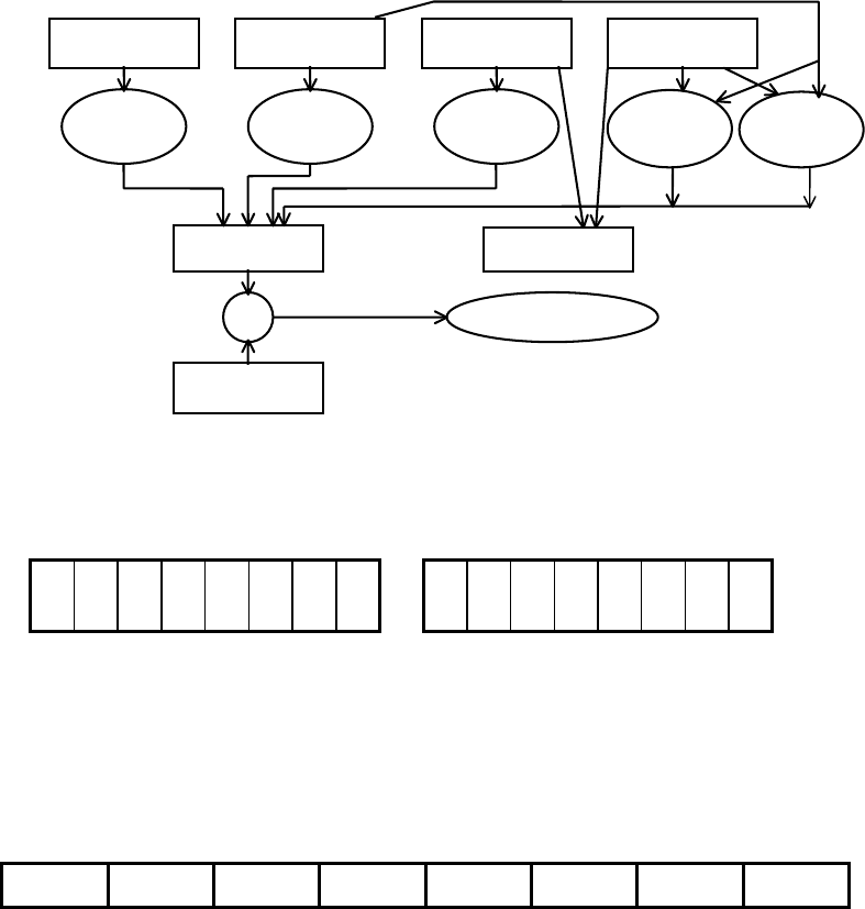
IEEE 488.2 compatible Status Structures Status reporting
The following illustrates the Power Module Status Structure:
sense warning condition
Error Code Faults Output Warnings
new new any positive negative
error fault change transition transition
Events Status
& Summary Bit
Enable
Power Modules Summary Register - read with SRQS?
The Power Module Status Summary Bit is placed in the bit position corresponding to the
Power Module’s channel number in the Power Modules Summary Register:
1
6
1
5
1
4
1
3
1
2
1
1
1
0
0
9
0
8
0
7
0
6
0
5
0
4
0
3
0
2
0
1
High Byte Low Byte
The Power Modules Summary Register is cleared when read.
XMP 2600
System
Status
Structure
The following status structure refers to the XMP 2600 main controller.
Standard Event Status Register - read with *ESR?
PON 0 CME EXE DDE QYE 0 OPC
PON ................ set when a Power On event occurs.
CME................ set when the XMP 2600 detects a Command Error.
EXE................. set when the XMP 2600 detects an Execution Error.
DDE ................ set when the XMP 2600 detects a XMP 2600 Error Condition.
QYE ................ set when the XMP 2600 detects a Query Error.
OPC................. Operation Complete - set by the OPC Command.
The register is cleared when read. If operating in 488.2 mode then the Summary Message
ESB is cleared and <rqs> and <ist> are re-calculated.
Command Error is reported when the XMP 2600 detects Syntax or Semantic error in the
input stream.
Execution Error is reported when the XMP 2600 detects an error in the parameters of a
Command or Query or when the Command or Query can not be executed due to some
condition.
Query Error is reported when the Remote Controller is trying to read data from the
Output Queue when it is empty and no Command or Query are being executed or even
present in the Input Queue. Query Error is, also, reported when the Remote Controller has
72 XMP 2600 Programming Manual rev. 1.1

Status reporting IEEE 488.2 compatible Status Structures
not finished reading a response (from the Output Queue) and is already sending new data.
Lastly, Query Error is reported when there is a Deadlock situation: Output Queue and
Input Queue are both full. This situation is unlikely to happen due to the Input Queue
being able to hold several Commands and Queries.
Standard Event Status Enable Register - set with *ESE read
with *ESE?
PON 0 CME EXE DDE QYE 0 OPC
The Register has the same structure as the Standard Event Status Register.
Performing a bit by bit AND between the Event Register and the Event Enable Register
and then ORing the resulting bits, generate the Status Summary Message ESB (Event
Summary Bit).
Setting new value to the Register causes a re-calculation of ESB and <rqs>.
Primary Status Register - read with PSR?
PRIM
OT
PRIM
FLT
EXT
SHUT
P_M
SHUT
PRIM
SHUT
PWR
ERR
PWR
WRN
PRIM
INP
PRIM_OT ........Primary Over Temperature.
PRIM_FLT ......Primary is faulty (its output is down).
EXT_SHUT .....Primary is shutdown by user (external signal).
P_M_SHUT .....Primary is shutdown by a Power Module.
PRIM_SHUT ...Primary is shutdown due to Power Error or Channel Fault.
PWR_ERR.......Primary Power Envelope exceeded - shutdown.
PWR_WRN .....Primary Power Envelope exceeded - warning zone.
PRIM_INP .......Primary input error (power fail).
The Primary Status Register shows the current status of the Primary.
Primary Event Status Register - read with PER?
PRIM
OT
PRIM
FLT
EXT
SHUT
P_M
SHUT
PRIM
SHUT
PWR
ERR
PWR
WRN
PRIM
INP
The Primary Event Status Register has the same structure as the Primary Status Register.
The bits in the Event Register are “sticky” - once a bit is set it will remain set even if the
condition that caused it to be set is no longer valid.
The register is cleared when read and <rqs> and <ist> are re-calculated.
Primary Event Status Enable Register - set with PEE, read
with PEE?
PRIM
OT
PRIM
FLT
EXT
SHUT
P_M
SHUT
PRIM
SHUT
PWR
ERR
PWR
WRN
PRIM
INP
The Primary Event Status Enable Register has the same structure as the Primary Status
Register.
The Status Summary Message PRIM_ERR is calculated by performing a bit by bit AND
between the Primary Event Status Register and the Primary Event Status Enable Register
and then ORing the resulting bits.
XMP 2600 Programming Manual rev. 1.1 73
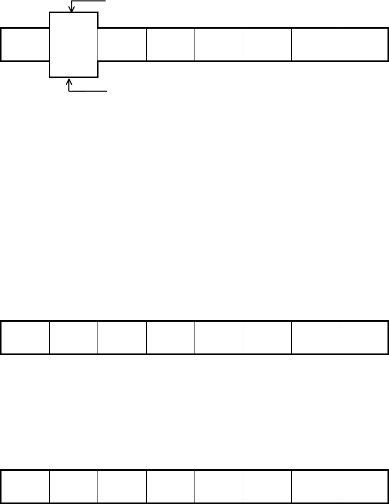
IEEE 488.2 compatible Status Structures Status reporting
Status Byte Register - read with *STB?
read by Serial Poll
RQS
0 ESB MAV Comm.
T.O.
PRIM
ERR
0 SRQ IS
MSS
read by *STB?
RQS................. the IEEE 488.1 Service Request Flag read by Serial Poll.
MSS ................ the Master Summary Status is generated by performing a bit by bit AND
of the Status Byte and the Service Request Enable Register and then
ORing the resulting bits.
ESB ................. the Event Summary Bit generation is described under Standard Event
Status Enable Register.
MAV ............... the Message Available Status Bit is set when there is data in the Output
Queue.
Comm. T.O. .... set when a communication time out event occurs. Cleared when the
TORST command is issued.
PRIM_ERR..... this is the Primary Status Summary Bit.
SRQ_IS ........... this is the Channels Events Summary Bit.
Service Request Enable Register - set with *SRE, read with
*SRE?
0 0 ESB MAV Comm.
T.O.
PRIM
ERR
0 SRQ IS
The Service Request Enable Register has mask bits at positions corresponding to the
status bits of the Status Byte. Unused bits are cleared.
The SRE Register is used for calculating the MSS and RQS flags.
Parallel Poll Enable Register - set with *PRE, read with
*PRE?
0 0 ESB MAV Comm.
T.O.
PRIM
ERR
0 SRQ IS
The Parallel Poll Enable Register has mask bits at positions corresponding to the status
bits of the Status Byte. Unused bits are cleared.
The PRE Register is used for calculating the IEEE 488.1 IST (Individual Status) message
(as read by the Remote Controller during a Parallel Poll).
74 XMP 2600 Programming Manual rev. 1.1
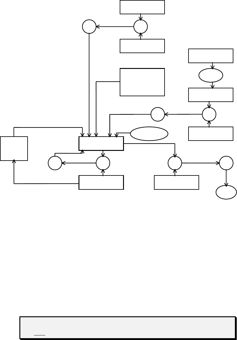
Status reporting Self Test Results
The following illustrates the System Status Structure:
EVENT
OR &
ENABLE
PRIMARY
OUTPUT SET
QUEUE
EVENT
OR &
channels
ENABLE
SRQ STATUS
GEN
OR & & OR
ENABLE ENABLE
IST
Self Test Results
The XMP 2600 enables its user to conduct two types of self-tests: Power Module self-test
and main controller’s self-test.
Power
Modules
The Power Module Test or Confidence Test result is made out of two bytes. The first byte
is the result of the latest performed test, and the second byte is the result of an on-going
confidence test of the analog section of the controlling circuits.
The results of the tests can be remotely read using the CONF? <ch> query.
The CONF? <ch> query will return the results of the latest test performed
and initiates a run of the Confidence Test.
XMP 2600 Programming Manual rev. 1.1 75

Self Test Results Status reporting
BYTE 1
ANLG
MUX
DAC ANLG
REF
PWR
SUPPL
NOVR
AM_B
NOVR
AM_A
PROG
MEM
INT
RAM
INT_RAM....... Processor Memory.
PROG_MEM .. Program Memory.
NOVRAM_A.. Non-Volatile Memory A.
NOVRAM_B .. Non-Volatile Memory B.
PWR_SUPPL.. Control circuits power supplies
ANLG_REF .... Analog section reference voltage.
DAC................ Digital to Analog Converter.
ANLG_MUX .. Analog signal paths.
Light shaded bits are of tests performed during Power-On only.
Dark shaded bits are of tests performed during both Power-On and Power
Module Test.
A set bit indicates a fault.
BYTE 2
VSET IOUT VLOAD VOUT
VOUT ............. VOUT measurement confidence test.
VLOAD .......... VLOAD measurement confidence test.
IOUT............... IOUT measurement confidence test.
VSET .............. VSET controlling signal confidence test.
Main
Controller
The Main Controller Confidence Test result is a single byte.
The results of the test can be remotely read using the CONF? query.
The result byte has the following format:
BUFF
AREA
SAVE
AREA
TABLE
AREA
INT
RAM
INT_RAM.............Processor Memory.
TABLE_AREA.....Main Memory - internal tables.
SAVE_AREA .......Main Memory - settings storage areas.
BUFF_AREA........Main Memory - communications buffers.
76 XMP 2600 Programming Manual rev. 1.1
Status reporting Error Codes summary
Error Codes summary
The following is a list of error codes generated by the Power Modules and the main
controller of the XMP 2600.
Errors Reported by the Power Module
Power
Modules 1 Processor Watchdog was activated.
7 Severe OCP error - output did not shut down.
8 Severe OVP error - output did not shut down.
9 Test error - VOUT zero test failed.
10 Test error - half the full scale VOUT test failed.
11 Test error - OVP circuit did not trip.
12 Test error - OVP circuit did not reset.
13 Output did not shut down.
14 Sense lines voltage drop exceeded 4V.
15 Current Limit was active following a three seconds period of the output being set
to zero voltage during a Retry Foldback.
16 Test error - output current was not zero during the output test.
17 Internal Communication Time Out.
18 Internal Communications buffer overflow.
19 output voltage did not drop to zero during the reprogramming period when the
relays were operated.
20 Internal Communication Checksum error.
21 Illegal command in the Internal Communications.
22 Internal Communications Command Error.
Errors Detected by the Main Controller
78 Internal Communications Time Out.
251 Internal Communications response by the Power Module was in error.
Errors detected during Channels Scan at Power-On
240 Internal Communications Time Out - Power Module not installed.
241 Power Module has failed its self-test.
242 Internal Communications response by the Power Module was in error.
244 Power Module did not respond with RDY.
247 The Power Module reported spec data did not match the internal table.
Errors detected during Retain or Recall
248 Internal Communications Time Out - Power Module not installed.
Power Modules Communications errors
Main
Controller 1 Error during channels scan (power-on).
2 Power Module’s response to status query was in error.
3 Communications Interrupt Line is asserted and no Power Module responded to
scan.
4 Internal communication receive buffer was full.
XMP 2600 Programming Manual rev. 1.1 77
Error Codes summary Status reporting
16 Internal Communications Time Out for Power Module in channel 1.
17 Internal Communications Time Out for Power Module in channel 2.
18 Internal Communications Time Out for Power Module in channel 3.
19 Internal Communications Time Out for Power Module in channel 4.
20 Internal Communications Time Out for Power Module in channel 5.
21 Internal Communications Time Out for Power Module in channel 6.
22 Internal Communications Time Out for Power Module in channel 7.
23 Internal Communications Time Out for Power Module in channel 8.
24 Internal Communications Time Out for Power Module in channel 9.
25 Internal Communications Time Out for Power Module in channel 10.
26 Internal Communications Time Out for Power Module in channel 11.
27 Internal Communications Time Out for Power Module in channel 12.
28 Internal Communications Time Out for Power Module in channel 13.
29 Internal Communications Time Out for Power Module in channel 14.
30 Internal Communications Time Out for Power Module in channel 15.
31 Internal Communications Time Out for Power Module in channel 16.
RS232 Communications errors
32 Data received while DTR was off (receive buffer is full).
33 Transmit buffer is full.
34 Receive Parity Error.
GPIB Communications errors
48 Bus Error (reported by hardware).
49 Input Queue was full so the Bus Trigger command can not be executed.
50 Input Queue was full so the EOI message (set on last character which is not a LF)
can not be processed.
Parser and Execution errors
37 Communications Driver error (false End Of Command).
39 The Parser lost synchronization with the Input Stream (processing a non-existing
command).
64 a miss-placed CR in the Input Stream.
65 Command or Query Mnemonics are too long (more than 6 characters).
66 Illegal Command or Query (first character).
67 Illegal Command or Query.
68 Missing parameter (value).
69 Non-digit character in Numeric Parameter..
70 Parameter value overflow.
71 Parameter value is less than zero (negative).
72 Not a valid Channel Number (should be in the range 1 to 16).
73 Parameter value is out of its allowed range.
74 Can not display the string.
75 The referenced Channel has no operative Power Module installed.
76 The referenced Storage Area is empty - no data to recall.
77 Protection settings can not be programmed (Auto Protection Mode is on).
78 XMP 2600 Programming Manual rev. 1.1
Status reporting Error Codes summary
XMP 2600 Programming Manual rev. 1.1 79
79 Can not turn Global On while a Channel Shut is in effect.
80 No Polarity Relays installed for the referenced Power Module.
81 No Disconnect Relay installed for the referenced Power Module.
82 The XMP 2600 is not in 488.2 Mode.
83 The XMP 2600 is in 488.2 Mode.
84 Can not clear the Sequence Program while it is running.

Xantrex Technology Inc.
604 422 2777 Tel
604 420 2145 Fax
800 670 0707 Toll Free North America
customerservice@xantrex.com
www.xantrex.com
TM-XMPM-11XN Printed in Israel
