XceedID XF1550WMTB Access Control Reader 125 kHz User Manual
XceedID Corporation Access Control Reader 125 kHz Users Manual
XceedID >
Users Manual

Install Guide XF1550P 125 kHz Reader
XF1500P XF1500CS4
1 - Installation Sheet
1 - Mounting Plate
1 - Cover
1 - Potted Reader
Assembly
2 - Mounting Screws
1 - Cover Assembly Screw
1 - Installation Sheet
1 - Mounting Plate
1 - Cover
1 - Potted Reader Assembly
2 - Mounting Screws
1 - Cover Assembly Screw
1 - Pigtail with Connector
MOUNTING THE READER
1. Determine an appropriate mounting position on a single gang box or wall. Be sure to account
for any applicable ADA height requirements.
2. For a single gang box mount, attach the back-plate to the holes in the single gang box using
the screws provided.
3. For a wall mount, drill two mounting holes between 2.5” (63.5mm) and 3.5” (88.9mm) apart
on the mounting surface. Drill one 3/4” (19.1 mm) diameter cable hole for the pigtail wire
connection.
4. Connect the mounting plate to the wall using the screws provided.
5. Wire the unit according to the color code chart below ensuring that all connections are made
through the center hole in the mounting plate.
7. Hook the top of the potted case assembly to the top of the mounting plate.
8. Swivel the unit down into place and snap the cover over the potted reader assembly.
9. Install the screw from the bottom to fix the cover to the potted case to the mounting plate.
CABLE CONNECTIONS
1. XceedID XF1550P readers are supplied with a 12 conductor cable pigtail.
2. Connect this pigtail with the host/panel being careful to match the color of each wire with the
chart shown in Figure 1.
3. Use a DC power source between 5 volts and 16 volts.
4. Be sure the reader is properly grounded by attaching the ground wire to an earth ground
connection at the power supply or panel end of the cable.
Testing the Reader
1. Power up the reader. The LED will light followed by a beeper tone. This indicates that the
reader is ready.
2. Present a proper card or token programmed to operate the reader and a green LED flash will
indicate successful operation. Note that a red flash could simply indicate an incorrect match or
miss-programmed card/token rather than a faulty reader installation.
Additional Notes
• The voltage specification for these products is 5*-16VDC.
• Typical cable gauge ranges from 18 to 22 gauge. Check with your cable supplier to determine
the best choice for your application and installation distance.
Specifications
• Excitation Frequency: 125 kHz
• Power Supply: DC
• Voltage Range: 5* – 16VDC
• Current Range: 100 mA average, 130mA peak
• Temperature Range: -31C to 65C (-25F to 149F)
• Card Read Distance: Up to 3.0” (76.2 mm) – Distance can vary widely depending on installation
conditions and credential type.
• Cable Distance to Panel in Wiegand mode:
-500 ft. maximum @ 22 awg for 12 volt supply.
-*100 ft. maximum @ 22 awg for 5 volt supply.
• Information Output: Wiegand = up to 64 bits
• Regulatory Approvals and Standards:UL 294, ISO15693, ISO14443A, Europe: CE Listed.
FCC Statement
The FCC requires the following statement for your information: This device complies with Part 15
of the FCC Rules. Operation is subject to the following two conditions: (1) this device may not
cause harmful interference, and (2) this device must accept any interference received, including
interference that may cause undesired operation. This reader utilizes and radio frequency energy
and has been tested and complies with the limits of FCC testing. Changes, modifications or
disregard of proper installation instructions not expressly approved by XceedID Corporation is
strictly prohibited by the FCC and could void the user’s authority to operate the equipment.
For Canadian Users
This unit has been tested and meets all applicable Industry of Canada technical specifications:
• Operation is subject to the following two conditions: (1) this device may not cause interference,
and (2) this device must accept any interference, including interference that may cause undesired
operation of the device.
For European Union Users
This unit has been tested and determined compliant to the following European Standards:
• Safety (art 3.1.a): EN50130-4 (1995 W/A1: 98 & A2: 03)
• EMC (art 3.1.b): ETS EN 301 489-3 V1.4.1 (2002-8)
• SPECTRUM (art 3.2): EN 300 330-2 V1.3.1 (2006-4)
• 0976
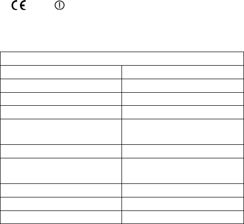
Figure 1. XF1550P wire connections
XF1550P
Green Data 0
White Data 1
Orange Green LED
Brown Red LED
Red Power + DC (5-16
VDC)
Black Ground
Tan Tamper Output
(External)
Pink Card Present
Yellow Beeper
Gray, Purple, Blue Not Used
Copyright © 2008, XceedID Corporation. All rights reserved. XceedID: Document No: 0542-03; Issue No. 1; 08/22/2008