Xeline LTd SU-200B PLC (PowerLine Communication) Modem User Manual
Xeline Co., LTd. PLC (PowerLine Communication) Modem
User Manual

SU-200B
Installation Manual
(For Technicians Only)
PLC Slave Unit
Plug into the future
Powerline Communication by Xeline
Xeline Co., Ltd.

SU-200B Installation Manual
This document is subject to change without prior notice.
2
ATTENTION
This equipment has been tested and found to comply with the limits for a Class B digital
device, pursuant to part 15 of the FCC Rules. These limits are designed to provide reasonable
protection against harmful interference in a residential installation. This equipment
generates, uses and can radiate radio frequency energy and, if not installed and used in
accordance with the instructions, may cause harmful interference to radio communications.
However, there is no guarantee that interference will not occur in a particular installation. If
this equipment does cause harmful interference to radio or television reception, which can be
determined by turning the equipment off and on, the user is encouraged to try to correct the
interference by one or more of the following measures:
Reorient or relocate the receiving antenna.
Increase the separation between the equipment and receiver.
Connect the equipment into an outlet on a circuit different from that to which the
receiver is connected.
Consult the dealer or an experienced radio/TV technician for help.
Change or modification not expressly approved by the party responsible for Compliance could
void the user’s authority to operate the equipment.
This equipment conforms with the following standard(s): EN60950

SU-200B Installation Manual
This document is subject to change without prior notice.
3
Table of Contents
1. Introduction······························································································· 5
2. Before Installing the SU-200B ·········································································· 6
2.1 Package Contents ························································································································ 6
2.2 Prerequisites································································································································· 6
2.3 Safety Precautions······················································································································· 7
3. Getting to Know the SU-200B··········································································· 8
3.1 Front View ···································································································································· 8
3.2 Rear View······································································································································ 8
3.3 Product Specifications················································································································· 9
3.4 Minimal Requirements for the Subscriber’s PC········································································ 9
4. Installing the SU-200B ··················································································10
4.1 Connecting the SU-200B to the Subscriber’s PC ···································································· 10
4.2 Configuring the Subscriber’s PC······························································································· 12
4.3 Final Check (Ping Test)·············································································································· 15
4.4 Resetting to Factory Default Mode·························································································· 17
5. Trouble Shooting·························································································18
6. Appendix··································································································19

SU-200B Installation Manual
This document is subject to change without prior notice.
4
Figure Index
Figure 1 XPAS-200B PLC Internet Access System Configuration...................................5
Figure 2 SU-200B Package Contents ..........................................................................6
Figure 3 SU-200B Front View..................................................................................... 8
Figure 4 SU-200B Rear View...................................................................................... 8
Figure 5 Connecting the RJ-45 cable and SU-200B................................................... 10
Figure 6 Connecting the Power Cable......................................................................10
Figure 7 Connecting the SU-200B to the Subscriber’s PC..........................................11
Figure 8 Network and Dial-up Connections..............................................................12
Figure 9 Local Area Connection Properties ..............................................................12
Figure 10 Internet Protocol (TCP/IP).......................................................................13
Figure 11 Fixed IP Address Setting...........................................................................13
Figure 12 Show Icon in TaskBar ............................................................................... 14
Figure 13 Network Configuration Complete............................................................. 14
Figure 14 Command Prompt Window.......................................................................15
Figure 15 Checking the Configured IP Address .........................................................15
Figure 16 Pinging the Default Gateway IP................................................................ 16
Figure 17 Checking the Ping Results ........................................................................ 17
SU-200B Installation Manual
This document is subject to change without prior notice.
5
1. Introduction
Powerline Communication (PLC) technology uses the existing powerline infrastructure to
transfer high-speed data, eliminating the need for expensive and complicated cable
installation. Because the home or office is already a ‘wired network’ through powerlines,
Xeline’s PLC system offers a cost-effective and easy-to-install Internet access solution from
any electrical outlet.
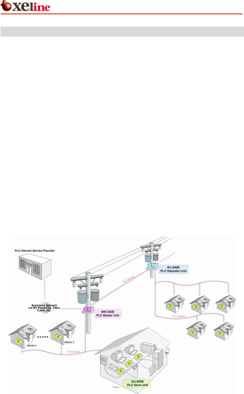
Xeline’s SU-200B is the PLC Slave Unit of the 24Mbps XPAS-200A PLC Internet Access System,
and is designed to enable the end-user to instantly access the Internet or home network from
any electrical outlet in the home or office. One SU-200B is needed for each PC or device that
you wish to connect to the network. Due to the smooth and high quality of data
communication, the SU-200B can also be used with various application equipment to provide
value-added services such as VoPL (Voice over Powerlines) and video conferencing.
The XPAS-200B system supports both Master/Slave or Ad-hoc topology and is based on Xeline's
proprietary Cell-structured MAC (CMAC), which offers virtually unlimited number of nodes per
physical network. Remote configuration and firmware upgrade are also supported for efficient
setup and maintenance of the PLC units in mass-usage environments.
Figure 1 XPAS-200B PLC Internet Access System Configuration

SU-200B Installation Manual
This document is subject to change without prior notice.
6
2. Before Installing the SU-200B
2.1 Package Contents
Before installing, first verify that you have all of the following items.
○ SU-200B PLC Slave Unit
○ 1 AC power cable ○ 1 Installation Manual ○ 1 RJ-45 cable (CAT 5)
* Core manufactured by: * Core manufactured by:
E-Tech Electronics Co., Ltd. E-Tech Electronics Co., Ltd.
Model No. cu1330b Model No. cu1330b
Figure 2 SU-200B Package Contents
If there is a missing item or any visible damage, notify your service provider or dealer
immediately.
2.2 Prerequisites
In order to install the SU-200B, you will need the following items:
(1) Power outlet
Plug the SU-200B directly into a wall outlet.
Note: Data rates may be affected when using an extension cord or power strip.
(2) Computer with 10/100 base-T Ethernet Network Interface Card

SU-200B Installation Manual
This document is subject to change without prior notice.
7
2.3 Safety Precautions
Please make sure to read the following instructions before handling the equipment.
(1) Read all instructions before installing or operating the equipment. Be sure to
keep this manual for further reference.
(2) Please follow all the safety precautions and other installation procedures.
(3) Do not use this product in the following environments:
- Extremely high or low temperatures
- High humidity areas or near water such as sinks or bathtubs
- Areas where sudden changes in temperature occur
- Under direct sunlight
(4) Do not use this equipment near heaters or other devices that emit high heat.
(5) Do not place heavy objects on top of the SU-200B.
(6) Turn off the SU-200B and unplug the cord before cleaning. Do not use liquid or
aerosol cleaners.
(7) If water or any other liquid is spilled on the device, turn off the power and
unplug the cord. Contact Xeline’s Technical Support Center. Continuing to use the
device may cause fire or an electric shock.
(8) Do not open, disassemble, or attempt to repair the device. If service or repair is
required, contact Xeline’s Technical Support Center. Incorrect reassembly can
cause electric shock when the equipment is subsequently used.
SU-200B Installation Manual
This document is subject to change without prior notice.
8
3. Getting to Know the SU-200B
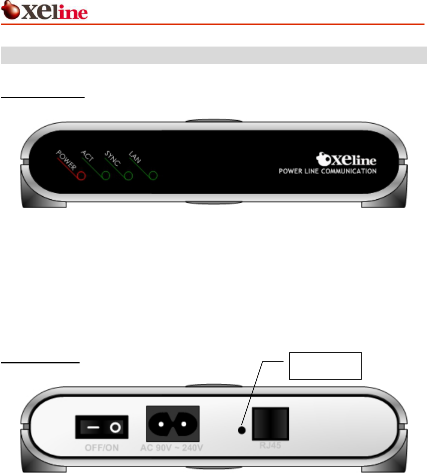
3.1 Front View
Figure 3 SU-200B Front View
PWR
Activates when power is turned on.
ACT
(PCS) Blinks when PLC signals are detected.
SYNC
(LINK) Blinks when the detected PLC signals are valid.
LAN
Activates when the SU-200B LAN port is connected to the PC.
Blinks during data transmission between the SU-200B and the PC.
3.2 Rear View
Reset button
Figure 4 SU-200B Rear View
RJ-45 Port RJ-45 Ethernet port for connection with the PC.
Reset Resets the SU-200B to factory default mode. (Caution!)
AC Inlet For connection to power cable.
Power Switch Switch for turning power ON/OFF.
SU-200B Installation Manual
This document is subject to change without prior notice.
9
3.3 Product Specifications
Specifications Remarks
Data rates Up to 24Mbps
Interface RJ-45 For connection with NIC
Dimensions 186 X 143 X 40mm (W x D x H)
Power AC110~240V, 50/60Hz
3.4 Minimal Requirements for the Subscriber’s PC
CPU Intel Pentium 166MHz or higher
Memory 32MB or more
OS Windows 95, 98, ME, 2000, NT, XP
Network Interface Card 10/100 base-T Ethernet Network Interface Card
SU-200B Installation Manual
This document is subject to change without prior notice.
10
4. Installing the SU-200B
4.1 Connecting the SU-200B to the Subscriber’s PC
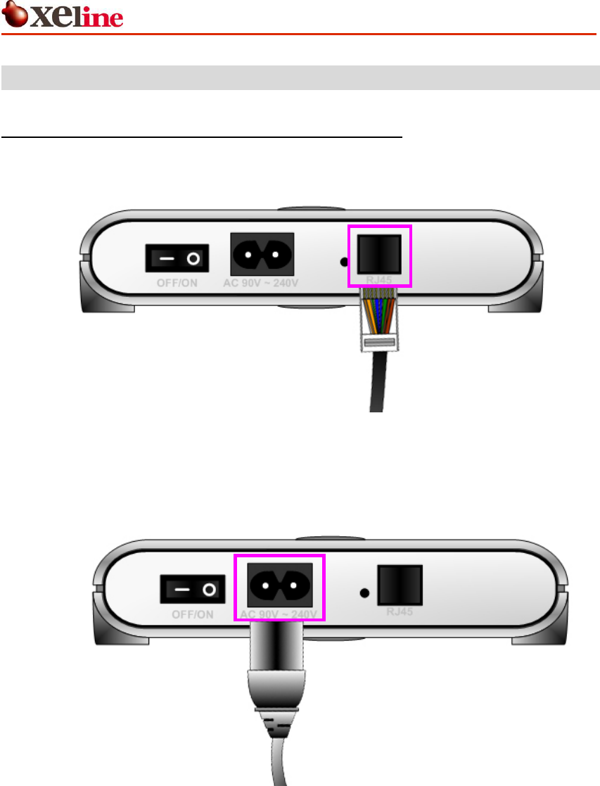
① Insert the RJ-45 cable into the RJ-45 Ethernet port of the SU-200B.
Figure 5 Connecting the RJ-45 cable and SU-200B
② Insert the power cable into the AC inlet of the SU-200B and plug the cable into a
power outlet.
Figure 6 Connecting the Power Cable
SU-200B Installation Manual
This document is subject to change without prior notice.
11
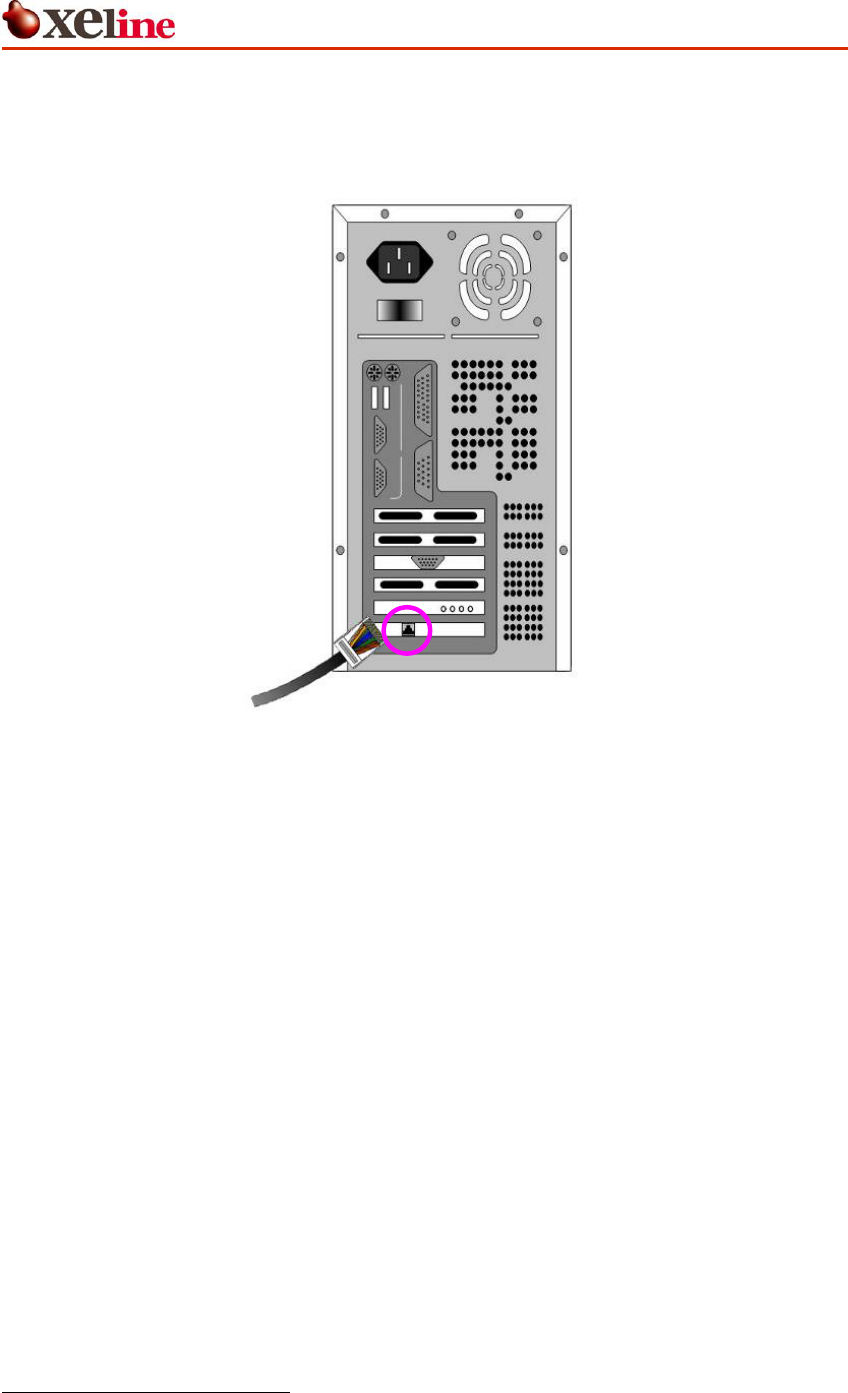
③ Connect the other end of the RJ-45 cable into the subscriber’s PC Network Interface
Card.
Figure 7 Connecting the SU-200B to the Subscriber’s PC
④ Turn on the power of the SU-200B and check if the LAN LED is activated.
⑤ The SU-200B is remotely configured by the EU-200B through automatic process.
Therefore there is no need to manually configure the SU-200B1.
⑥ Wait approximately 1 minute for the EU-200B to finish the remote configuration
process.
1 The EU-200B configures the Group ID and operation mode of the SU-200B during the remote
configuration process. Please refer to the EU-200B Installation Guide for more details.
SU-200B Installation Manual
This document is subject to change without prior notice.
12
4.2 Configuring the Subscriber’s PC
Note: The following IP setting example is based on Microsoft Windows 2000 Professional
operating system. Configuration procedures may differ according to the subscriber PC O/S.
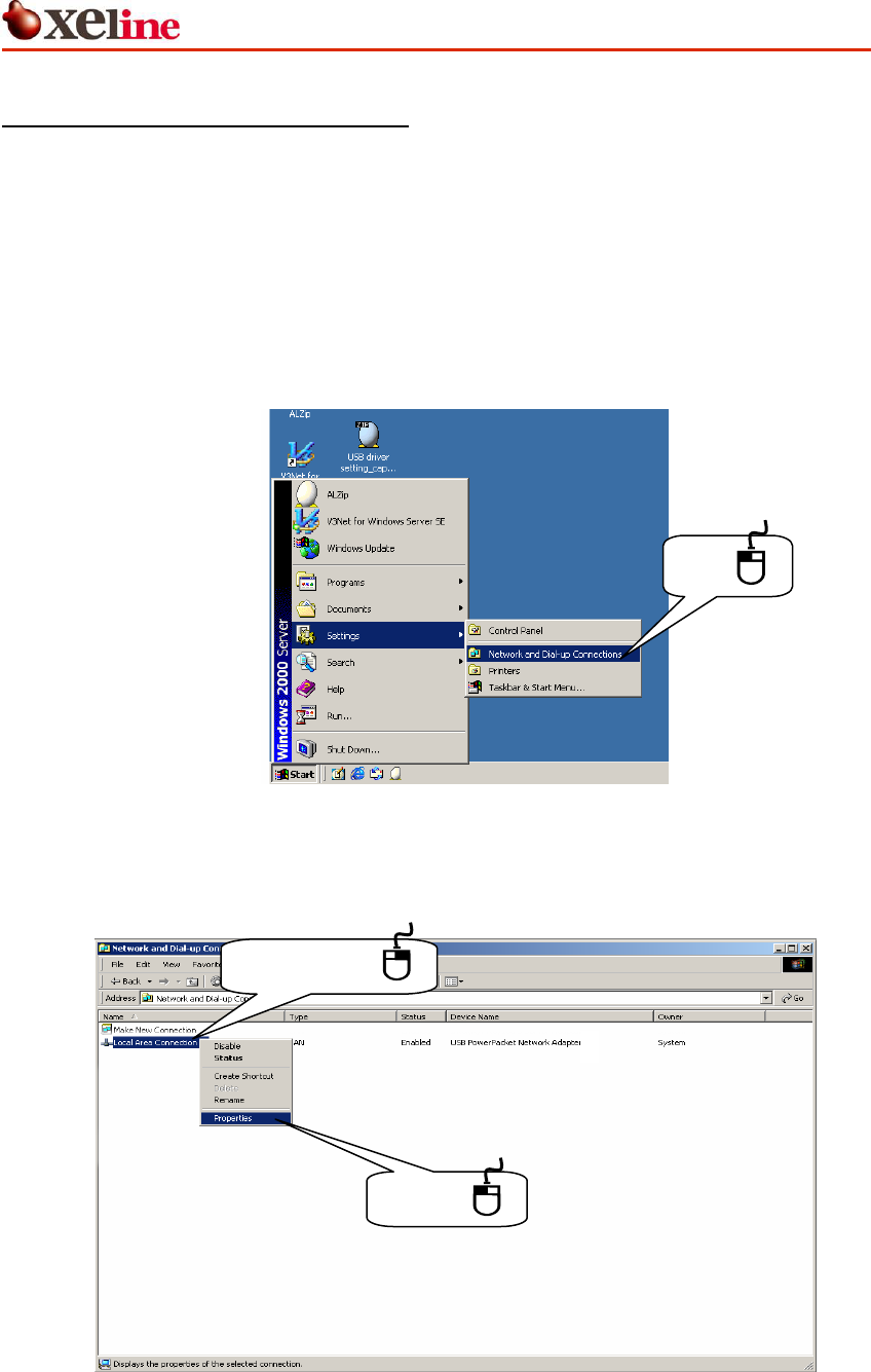
① Click the START button in your taskbar and go to NETWORK AND DIAL-UP
CONNECTIONS.
Go to: START Æ SETTINGS Æ NETWORK AND DIAL-UP CONNECTIONS
Click
Figure 8 Network and Dial-up Connections
② Right-click LOCAL AREA CONNECTION and select PROPERTIES.
(1) Right-click
(2) Click
Figure 9 Local Area Connection Properties
SU-200B Installation Manual
This document is subject to change without prior notice.
13
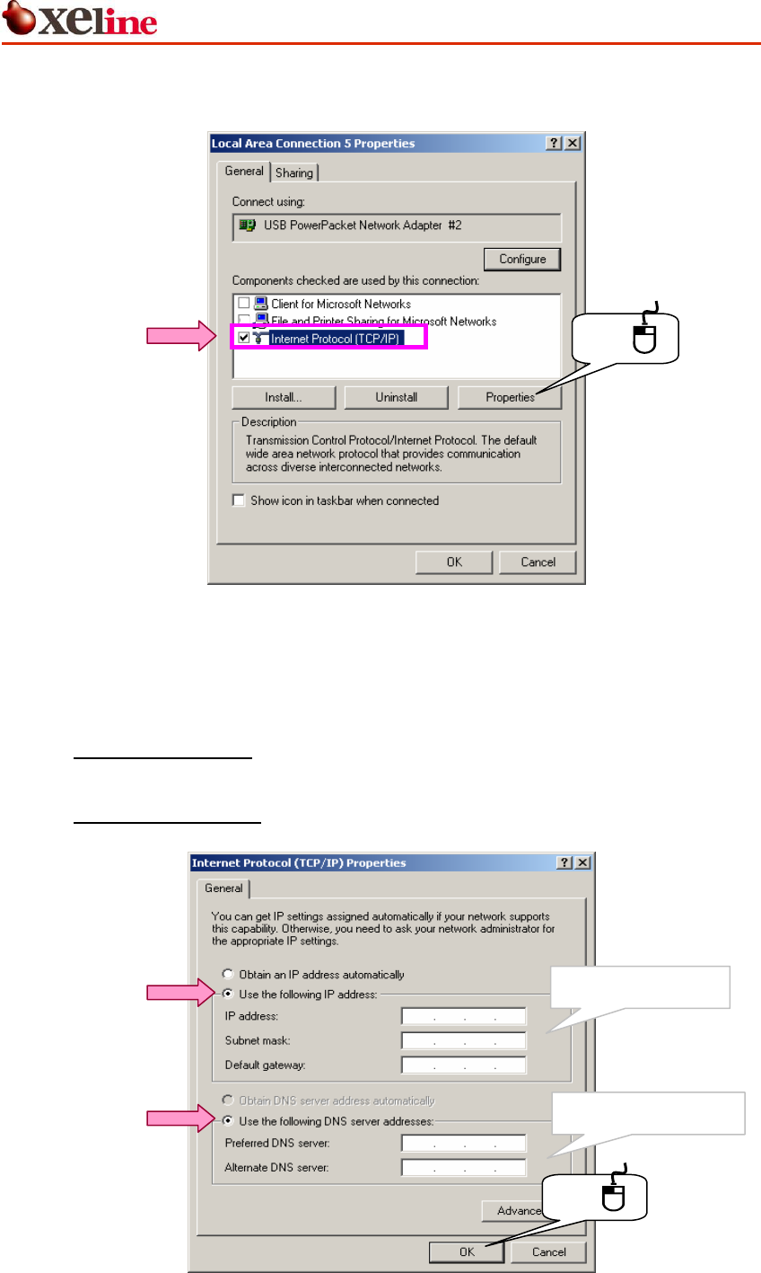
③ Select INTERNET PROTOCOL (TCP/IP) and click [Properties].
Click
Figure 10 Internet Protocol (TCP/IP)
④ Enter the IP address and DNS server address provided by the Internet Service
Provider (ISP).
i. For DHCP IP Addresses: Select OBTAIN AN IP ADDRESS AUTOMATICALLY. Then select the
OBTAIN THE FOLLOWING DNS SERVER ADDRESS option. Click [OK] to continue.
ii. For Fixed IP Addresses: Enter the addresses as shown in the example below. Click
[OK].
Click
147 46 80 2
147 46 80 1
211 168 11 129
255 255 255 128
211 168 11 249
Example DNS address
Example IP address
Figure 11 Fixed IP Address Setting
SU-200B Installation Manual
This document is subject to change without prior notice.
14
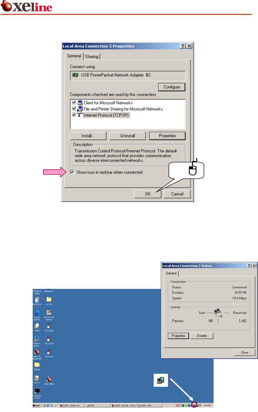
⑤ Select the SHOW ICON IN TASKBAR WHEN CONNECTED option and click [OK].
Click
Figure 12 Show Icon in TaskBar
⑥ Configuring your computer for Internet connection is now complete. You can check
your connection status by clicking the network icon in the taskbar as shown below.
Figure 13 Network Configuration Complete
SU-200B Installation Manual
This document is subject to change without prior notice.
15
4.3 Final Check (Ping Test)
Perform the following procedures in order to check if the installation is successful.
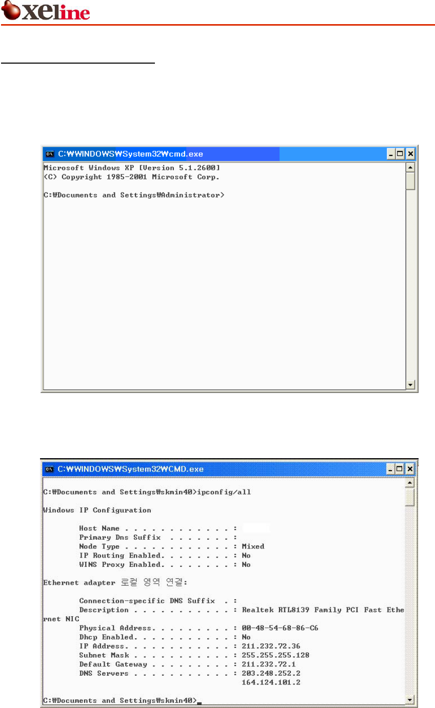
① Run Command window
Go to: START Æ RUN.. Æ CMD
Figure 14 Command Prompt Window
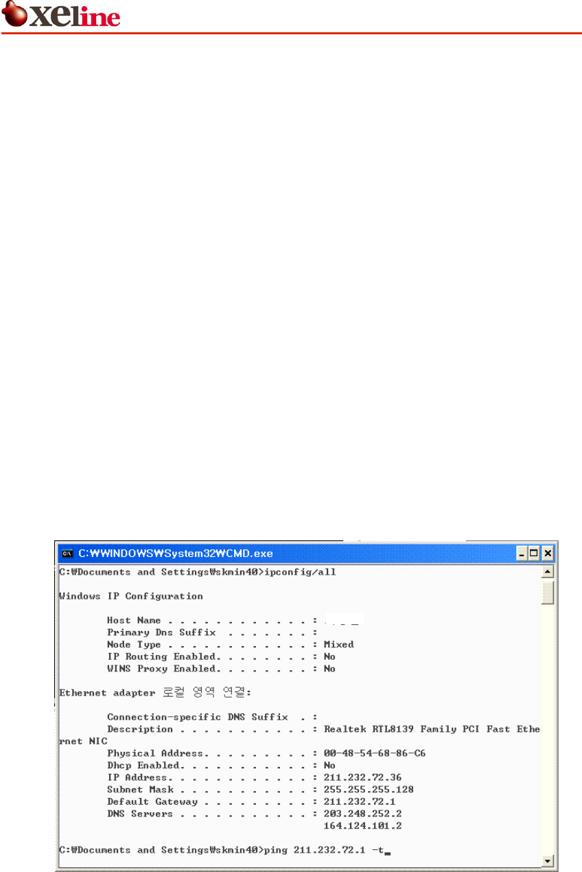
② Type <ipconfig /all> and press ENTER key
Figure 15 Checking the Configured IP Address
SU-200B Installation Manual
This document is subject to change without prior notice.
16
③ In case of DHCP:
- Physical Address : XX-XX-XX-XX-XX-XX Check
- DHCP Enabled : Yes
- IP Address : Check (Any IP)
- Subnet Mask : Check (Any Subnet Mask)
- Default Gateway : Check (Any Gateway)
- DNS Servers : Check (Any DNS Servers)
④ In case of Fixed IP:
- Physical Address : XX-XX-XX-XX-XX-XX Check
- Dhcp Enabled : No
- IP Address : Check (Configured IP)
- Subnet Mask : Check (Configured Subnet Mask)
- Default Gateway : Check (Configured Gateway)
- DNS Servers : Check (Configured DNS Servers)
⑤ Check the default Gateway IP address and perform ping tests. The command is as
follows:
< ping Default Gateway IP –t >
Figure 16 Pinging the Default Gateway IP
SU-200B Installation Manual
This document is subject to change without prior notice.
17
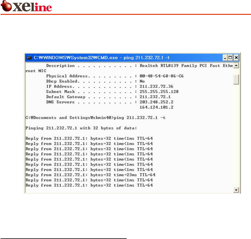
⑥ Installation is successful if the following message appears.
< Reply from Default Gateway IP: bytes=32 time<xxms TTL=64 >
Figure 17 Checking the Ping Results
4.4 Resetting to Factory Default Mode
Use the reset button at the back of the SU-200B in order to reset the configuration into
factory default mode.
① Turn off the power of the SU-200B.
② Disconnect the RJ-45 cable.
③ Use a long sharp instrument (such as a tweezers) in order to push down on the reset
button.
④ Turn on the SU-200B while pushing down on the reset button.
⑤ Using the tweezers, push down on the reset button for 1 second. Wait at least 1
second before repeating the procedure. Repeat 3 times or more.
⑥ The LINK LED will blink when the SU-200B is changed to the factory default mode.
⑦ Reset the power.

SU-200B Installation Manual
This document is subject to change without prior notice.
18
5. Trouble Shooting
Problem Checklist
The POWER LED does not
activate.
Check if the power cable is firmly plugged into the SU-200B and
power outlet.
The ACT and SYNC LEDs do
not activate.
This can occur when the PLC link is not possible or the channel
conditions are poor.
Try plugging the SU-200B directly into a wall outlet. (When using
a power strip, the other connected electrical appliances can
affect the performance of the SU-200B.)
The LAN LED does not
activate.
Check if the RJ-45 cable is firmly plugged into the SU-200B and
the NIC of the PC.
Check if the NIC connection is disabled in the Local Area Network
window.
Pinging to the default
Gateway IP is
unsuccessful.
① Check for typos in the ping command.
② Check if the Gateway IP address is correct.
③ Check the IP configuration of the subscriber’s PC.
④ If the IP configuration is correct, the problem lies in the ISP
backbone. Check if it is possible to ping to a gateway at
another location.
The IP address does not
appear correctly in the
‘ipconfig /all’ command
prompt window.
(1) DHCP IP Address
① Open the command prompt window. Type ‘ipconfig /renew’.
② Type ‘ipconfig /all’ to recheck the IP address.
(2) Fixed IP Address
① Reconfigure the IP settings according the manual.
② Type ‘ipconfig /all’ to recheck the IP address.
If the problem is still not solved, please contact Xeline’s Technical Support Center.

SU-200B Installation Manual
This document is subject to change without prior notice.
19
6. Appendix
z Copyright 2005 Xeline Co., Ltd. All rights reserved.
All Xeline brand product names are trademarks of Xeline Co., Ltd.
Other product and company names mentioned herein are the trademarks of their
respective owners.
z Information in this document is subject to change without notice. No part of this document
may be reproduced or transmitted in any form or by any means, electronical or
mechanical, for any purpose, without the express written permission of Xeline Co., Ltd.
z Xeline Technical Support Center
Address: 7F. Chungjin Bldg. 475-22,
Bangbae 2 dong, Seocho-gu,
Seoul 137-819, Republic of Korea
Telephone: +82 2 598 0980
Facsimile: +82 2 598 0975
E-mail: tech_support@xeline.com
Website: http://www.xeline.com