Xerox If Not Then DP100 115 135 155 180 IPG 0405
User Manual: Xerox If not then Manual: ://.support.xerox.com/pub/docs/DocuPrint_100_100MX/userdocs/any-os/en/DP100-115-135-155-180_IPG-0405
Open the PDF directly: View PDF ![]() .
.
Page Count: 124 [warning: Documents this large are best viewed by clicking the View PDF Link!]
- Safety
- Introduction
- 1 Product overview
- 2 Controller components and options
- 3 Printer components and options
- 4 Preparing for installation
- 5 Controller requirements and specifications
- 6 Printer requirements and specifications
- 7 System connections
- 8 Installation
- A Supplies
- B Xerox support services
- C Related publications
- Index

installation
Xerox DocuPrint 100/115/135/155/180 EPS
701P24750
April, 2005
guide
planning

Prepared by:
Xerox Corporation
Global Knowledge and Language Services
800 Philips Road Bldg. 845-17S
Webster, New York 14580
USA
©2005 by Xerox Corporation. All rights reserved.
Copyright protection claimed includes all forms and matters of copyrightable material and information
now allowed by statutory judicial law or hereinafter granted, including without limitation, material generated
from the software programs displayed on the screen such as icons, screen displays, or looks.
Printed in the United States of America.
XEROX® and all Xerox product names mentioned in this publication are trademarks of XEROX CORPORATION.
Other company trademarks are also acknowledged.
Changes are periodically made to this document. Changes, technical inaccuracies, and
typographic errors will be corrected in subsequent editions.

Installation Planning Guide i
Table of contents
Safety
Laser safety . . . . . . . . . . . . . . . . . . . . . . . . . . . . . . . . . . . . . . . . . . . . . . . . . . . . . . . . . . . . . . . . . . v
Ozone information: U. S. only . . . . . . . . . . . . . . . . . . . . . . . . . . . . . . . . . . . . . . . . . . . . . . . . . . . . . v
Operation safety: U. S. . . . . . . . . . . . . . . . . . . . . . . . . . . . . . . . . . . . . . . . . . . . . . . . . . . . . . . . . . .vi
Operation safety: Europe . . . . . . . . . . . . . . . . . . . . . . . . . . . . . . . . . . . . . . . . . . . . . . . . . . . . . . . vii
Warning markings . . . . . . . . . . . . . . . . . . . . . . . . . . . . . . . . . . . . . . . . . . . . . . . . . . . . . . vii
Electrical supply . . . . . . . . . . . . . . . . . . . . . . . . . . . . . . . . . . . . . . . . . . . . . . . . . . . . . . . vii
Ventilation . . . . . . . . . . . . . . . . . . . . . . . . . . . . . . . . . . . . . . . . . . . . . . . . . . . . . . . . . . . . viii
Operator accessible areas . . . . . . . . . . . . . . . . . . . . . . . . . . . . . . . . . . . . . . . . . . . . . . . viii
Maintenance . . . . . . . . . . . . . . . . . . . . . . . . . . . . . . . . . . . . . . . . . . . . . . . . . . . . . . . . . .viii
Before cleaning your product . . . . . . . . . . . . . . . . . . . . . . . . . . . . . . . . . . . . . . . . . . . . . viii
CE mark: Europe only . . . . . . . . . . . . . . . . . . . . . . . . . . . . . . . . . . . . . . . . . . . . . . . . . . . . . . . . . . viii
Radio and telecommunications equipment directive . . . . . . . . . . . . . . . . . . . . . . . . . . . . . . . . . . . .ix
Europe only . . . . . . . . . . . . . . . . . . . . . . . . . . . . . . . . . . . . . . . . . . . . . . . . . . . . . . . . . . . .ix
For further information . . . . . . . . . . . . . . . . . . . . . . . . . . . . . . . . . . . . . . . . . . . . . . . . . . . . . . . . . . x
Introduction
About this guide . . . . . . . . . . . . . . . . . . . . . . . . . . . . . . . . . . . . . . . . . . . . . . . . . . . . . . . . . . . . . . .xi
Contents . . . . . . . . . . . . . . . . . . . . . . . . . . . . . . . . . . . . . . . . . . . . . . . . . . . . . . . . . . . . . .xi
Conventions . . . . . . . . . . . . . . . . . . . . . . . . . . . . . . . . . . . . . . . . . . . . . . . . . . . . . . . . . . xii
Notice . . . . . . . . . . . . . . . . . . . . . . . . . . . . . . . . . . . . . . . . . . . . . . . . . . . . . . . . . . . . . . . . . . . . . . xiii
1 Product overview
System overview . . . . . . . . . . . . . . . . . . . . . . . . . . . . . . . . . . . . . . . . . . . . . . . . . . . . . . . . . . . . 1-1
System components . . . . . . . . . . . . . . . . . . . . . . . . . . . . . . . . . . . . . . . . . . . . . . . . . . . . . . . . . . 1-2
Client workstations and system software . . . . . . . . . . . . . . . . . . . . . . . . . . . . . . . . . . . . . . . . . . 1-4
Supported hardware and operating systems . . . . . . . . . . . . . . . . . . . . . . . . . . . . . . . . 1-5
Client networking software . . . . . . . . . . . . . . . . . . . . . . . . . . . . . . . . . . . . . . . . . . . . . . 1-5
MICR printing features . . . . . . . . . . . . . . . . . . . . . . . . . . . . . . . . . . . . . . . . . . . . . . . . . 1-5
MICR fonts . . . . . . . . . . . . . . . . . . . . . . . . . . . . . . . . . . . . . . . . . . . . . . . . . . . . 1-6
Unsupported features . . . . . . . . . . . . . . . . . . . . . . . . . . . . . . . . . . . . . . . . . . . . 1-7
Host connectivity options . . . . . . . . . . . . . . . . . . . . . . . . . . . . . . . . . . . . . . . . . . . . . . . . . . . . . . 1-7
Remote Services . . . . . . . . . . . . . . . . . . . . . . . . . . . . . . . . . . . . . . . . . . . . . . . . . . . . . . . . . . . . 1-8
2 Controller components and options
Controller overview . . . . . . . . . . . . . . . . . . . . . . . . . . . . . . . . . . . . . . . . . . . . . . . . . . . . . . . . . . . 2-1
Controller components . . . . . . . . . . . . . . . . . . . . . . . . . . . . . . . . . . . . . . . . . . . . . . . . . . . . . . . . 2-1
Sun workstation . . . . . . . . . . . . . . . . . . . . . . . . . . . . . . . . . . . . . . . . . . . . . . . . . . . . . . . 2-2
Controller interface options . . . . . . . . . . . . . . . . . . . . . . . . . . . . . . . . . . . . . . . . . . . . . . . . . . . . 2-9
Online interface . . . . . . . . . . . . . . . . . . . . . . . . . . . . . . . . . . . . . . . . . . . . . . . . . . . . . . . 2-9
Tape drive option . . . . . . . . . . . . . . . . . . . . . . . . . . . . . . . . . . . . . . . . . . . . . . . . . . . . 2-10
3 Printer components and options
Printer components . . . . . . . . . . . . . . . . . . . . . . . . . . . . . . . . . . . . . . . . . . . . . . . . . . . . . . . . . . 3-1

ii Installation Planning Guide
Table of contents
Printer configurations . . . . . . . . . . . . . . . . . . . . . . . . . . . . . . . . . . . . . . . . . . . . . . . . . . . . . . . . . 3-2
Bypass transport option . . . . . . . . . . . . . . . . . . . . . . . . . . . . . . . . . . . . . . . . . . . . . . . . . . . . . . . 3-3
Roll feeder support (DP155 and DP180 EPS only) . . . . . . . . . . . . . . . . . . . . . . . . . . . . . . . . . . 3-4
4 Preparing for installation
Responsibilities . . . . . . . . . . . . . . . . . . . . . . . . . . . . . . . . . . . . . . . . . . . . . . . . . . . . . . . . . . . . . 4-1
Xerox responsibilities . . . . . . . . . . . . . . . . . . . . . . . . . . . . . . . . . . . . . . . . . . . . . . . . . . 4-2
Customer responsibilities . . . . . . . . . . . . . . . . . . . . . . . . . . . . . . . . . . . . . . . . . . . . . . . 4-2
Installation planning checklist . . . . . . . . . . . . . . . . . . . . . . . . . . . . . . . . . . . . . . . . . . . . . . . . . . . 4-3
Connectivity requirements . . . . . . . . . . . . . . . . . . . . . . . . . . . . . . . . . . . . . . . . . . . . . . . . . . . . . 4-5
Ethernet specifications . . . . . . . . . . . . . . . . . . . . . . . . . . . . . . . . . . . . . . . . . . . . . . . . . 4-5
Token Ring specifications . . . . . . . . . . . . . . . . . . . . . . . . . . . . . . . . . . . . . . . . . . . . . . . 4-5
Channel-attached specifications . . . . . . . . . . . . . . . . . . . . . . . . . . . . . . . . . . . . . . . . . . 4-6
5 Controller requirements and specifications
Power requirements . . . . . . . . . . . . . . . . . . . . . . . . . . . . . . . . . . . . . . . . . . . . . . . . . . . . . . . . . . 5-1
Outlet configurations . . . . . . . . . . . . . . . . . . . . . . . . . . . . . . . . . . . . . . . . . . . . . . . . . . . 5-1
Environmental specifications . . . . . . . . . . . . . . . . . . . . . . . . . . . . . . . . . . . . . . . . . . . . . . . . . . . 5-3
Space requirements . . . . . . . . . . . . . . . . . . . . . . . . . . . . . . . . . . . . . . . . . . . . . . . . . . . . . . . . . . 5-3
Controller placement . . . . . . . . . . . . . . . . . . . . . . . . . . . . . . . . . . . . . . . . . . . . . . . . . . . 5-3
Guidelines for controller placement . . . . . . . . . . . . . . . . . . . . . . . . . . . . . . . . . . . . . . . . 5-4
Controller hardware specifications and requirements summary . . . . . . . . . . . . . . . . . . . . . . . . 5-4
6 Printer requirements and specifications
Power requirements . . . . . . . . . . . . . . . . . . . . . . . . . . . . . . . . . . . . . . . . . . . . . . . . . . . . . . . . . . 6-1
Outlet configurations . . . . . . . . . . . . . . . . . . . . . . . . . . . . . . . . . . . . . . . . . . . . . . . . . . . . . . . . . 6-2
60 Hz printer outlet voltages . . . . . . . . . . . . . . . . . . . . . . . . . . . . . . . . . . . . . . . . . . . . . 6-2
50 Hz printer outlet voltages . . . . . . . . . . . . . . . . . . . . . . . . . . . . . . . . . . . . . . . . . . . . . 6-3
Environmental specifications . . . . . . . . . . . . . . . . . . . . . . . . . . . . . . . . . . . . . . . . . . . . . . . . . . . 6-5
Space requirements . . . . . . . . . . . . . . . . . . . . . . . . . . . . . . . . . . . . . . . . . . . . . . . . . . . . . . . . . . 6-5
Printer configurations available . . . . . . . . . . . . . . . . . . . . . . . . . . . . . . . . . . . . . . . . . . . 6-6
Printer configuration diagrams . . . . . . . . . . . . . . . . . . . . . . . . . . . . . . . . . . . . . . . . . . . 6-6
Bypass transport specifications . . . . . . . . . . . . . . . . . . . . . . . . . . . . . . . . . . . . . . . . . . . . . . . . . 6-9
Bypass transport dimensions . . . . . . . . . . . . . . . . . . . . . . . . . . . . . . . . . . . . . . . . . . . 6-10
Configuration diagrams with bypass transport . . . . . . . . . . . . . . . . . . . . . . . . . . . . . . 6-12
Space planning guidelines . . . . . . . . . . . . . . . . . . . . . . . . . . . . . . . . . . . . . . . . . . . . . . . . . . . . 6-14
Clearance space requirements . . . . . . . . . . . . . . . . . . . . . . . . . . . . . . . . . . . . . . . . . . 6-15
Shared space between components . . . . . . . . . . . . . . . . . . . . . . . . . . . . . . . 6-15
Shared space configuration diagrams . . . . . . . . . . . . . . . . . . . . . . . . . . . . . . 6-15
Floor leveling . . . . . . . . . . . . . . . . . . . . . . . . . . . . . . . . . . . . . . . . . . . . . . . . . . . . . . . . 6-18
Delivery access requirements . . . . . . . . . . . . . . . . . . . . . . . . . . . . . . . . . . . . . . . . . . . 6-19
Turning radius . . . . . . . . . . . . . . . . . . . . . . . . . . . . . . . . . . . . . . . . . . . . . . . . 6-19
Printer hardware specifications and requirements summary . . . . . . . . . . . . . . . . . . . . . . . . . . 6-23
Space planning templates . . . . . . . . . . . . . . . . . . . . . . . . . . . . . . . . . . . . . . . . . . . . . . . . . . . . 6-26
7 System connections
Cable lengths . . . . . . . . . . . . . . . . . . . . . . . . . . . . . . . . . . . . . . . . . . . . . . . . . . . . . . . . . . . . . . . 7-1
Cable locations . . . . . . . . . . . . . . . . . . . . . . . . . . . . . . . . . . . . . . . . . . . . . . . . . . . . . . . . . . . . . . 7-1
Channel attachments . . . . . . . . . . . . . . . . . . . . . . . . . . . . . . . . . . . . . . . . . . . . . . . . . . . . . . . . . 7-2
8 Installation

Installation Planning Guide iii
Table of contents
Installation process . . . . . . . . . . . . . . . . . . . . . . . . . . . . . . . . . . . . . . . . . . . . . . . . . . . . . . . . . . . 8-1
Your responsibilities . . . . . . . . . . . . . . . . . . . . . . . . . . . . . . . . . . . . . . . . . . . . . . . . . . . . . . . . . . 8-2
Defining the printer to the host . . . . . . . . . . . . . . . . . . . . . . . . . . . . . . . . . . . . . . . . . . . . . . . . . . 8-2
Software licensing . . . . . . . . . . . . . . . . . . . . . . . . . . . . . . . . . . . . . . . . . . . . . . . . . . . . . . . . . . . 8-3
Ongoing maintenance . . . . . . . . . . . . . . . . . . . . . . . . . . . . . . . . . . . . . . . . . . . . . . . . . . . . . . . . 8-3
Routine maintenance . . . . . . . . . . . . . . . . . . . . . . . . . . . . . . . . . . . . . . . . . . . . . . . . . . 8-3
Meter reading and reporting . . . . . . . . . . . . . . . . . . . . . . . . . . . . . . . . . . . . . . . . . . . . . 8-4
A Supplies
Paper and other throughput stocks . . . . . . . . . . . . . . . . . . . . . . . . . . . . . . . . . . . . . . . . . . . . . . A-1
Selecting paper . . . . . . . . . . . . . . . . . . . . . . . . . . . . . . . . . . . . . . . . . . . . . . . . . . . . . . . A-1
Paper sizing and print speed . . . . . . . . . . . . . . . . . . . . . . . . . . . . . . . . . . . . . . . . . . . . . A-3
Paper width and throughput speed (LCDS printing only) . . . . . . . . . . . . . . . . . A-3
Paper size and pitch mode minimum and maximum . . . . . . . . . . . . . . . . . . . . A-5
Feed direction for standard paper sizes . . . . . . . . . . . . . . . . . . . . . . . . . . . . . . A-7
Paper care . . . . . . . . . . . . . . . . . . . . . . . . . . . . . . . . . . . . . . . . . . . . . . . . . . . . . . . . . . . A-9
Other supplies . . . . . . . . . . . . . . . . . . . . . . . . . . . . . . . . . . . . . . . . . . . . . . . . . . . . . . . . . . . . . A-11
Dry ink . . . . . . . . . . . . . . . . . . . . . . . . . . . . . . . . . . . . . . . . . . . . . . . . . . . . . . . . . . . . . A-12
Fuser agent . . . . . . . . . . . . . . . . . . . . . . . . . . . . . . . . . . . . . . . . . . . . . . . . . . . . . . . . . A-12
Developer . . . . . . . . . . . . . . . . . . . . . . . . . . . . . . . . . . . . . . . . . . . . . . . . . . . . . . . . . . A-12
Diskettes . . . . . . . . . . . . . . . . . . . . . . . . . . . . . . . . . . . . . . . . . . . . . . . . . . . . . . . . . . . A-13
Cartridge tapes . . . . . . . . . . . . . . . . . . . . . . . . . . . . . . . . . . . . . . . . . . . . . . . . . . . . . . A-13
Stacker containers and pallets (optional) . . . . . . . . . . . . . . . . . . . . . . . . . . . . . . . . . . A-13
Fonts . . . . . . . . . . . . . . . . . . . . . . . . . . . . . . . . . . . . . . . . . . . . . . . . . . . . . . . . . . . . . . A-13
Consumable supplies tables . . . . . . . . . . . . . . . . . . . . . . . . . . . . . . . . . . . . . . . . . . . . . . . . . . A-14
Paper and special stocks tables . . . . . . . . . . . . . . . . . . . . . . . . . . . . . . . . . . . . . . . . . A-14
Complete supplies list for the printer . . . . . . . . . . . . . . . . . . . . . . . . . . . . . . . . . . . . . . A-19
Ordering supplies . . . . . . . . . . . . . . . . . . . . . . . . . . . . . . . . . . . . . . . . . . . . . . . . . . . . . . . . . . . A-20
B Xerox support services
Xerox Customer Service Support Center . . . . . . . . . . . . . . . . . . . . . . . . . . . . . . . . . . . . . . . . . . B-1
Xerox Printing Systems Customer Support Center (U. S.) . . . . . . . . . . . . . . . . . . . . . . . . . . . . . B-2
Xerox Documentation and Software Services (U. S.) . . . . . . . . . . . . . . . . . . . . . . . . . . . . . . . . B-3
Operator training . . . . . . . . . . . . . . . . . . . . . . . . . . . . . . . . . . . . . . . . . . . . . . . . . . . . . . . . . . . . B-3
Xerox Customer Education . . . . . . . . . . . . . . . . . . . . . . . . . . . . . . . . . . . . . . . . . . . . . . . . . . . . B-3
Xerox Font Services . . . . . . . . . . . . . . . . . . . . . . . . . . . . . . . . . . . . . . . . . . . . . . . . . . . . . . . . . . B-4
C Related publications
DocuPrint 100/115/135/155/180 EPS documentation . . . . . . . . . . . . . . . . . . . . . . . . . . . . . . . . C-1
NPS/IPS publications . . . . . . . . . . . . . . . . . . . . . . . . . . . . . . . . . . . . . . . . . . . . . . . . . . . . . . . . . C-1
Index

iv Installation Planning Guide
Table of contents
Installation Planning Guide v
Safety
Laser safety
WARNING: Adjustments, use of controls, or performance of
procedures other than those specified herein may result in
hazardous light exposure.
The Xerox DocuPrint printers are certified to comply with the
performance standards of the U.S. Department of Health,
Education, and Welfare for Class 1 laser products. Class 1 laser
products do not emit hazardous radiation. The DocuPrint printers
do not emit hazardous radiation because the laser beam is
completely enclosed during all modes of customer operation.
The laser danger labels on the system are for Xerox service
representatives and are on or near panels or shields that must be
removed with a tool.
DO NOT REMOVE LABELED PANELS OR PANELS NEAR
LABELS. ONLY XEROX SERVICE REPRESENTATIVES HAVE
ACCESS TO THESE PANELS.
Ozone information: U. S. only
This product produces ozone during normal operation. The
amount of ozone produced depends on copy volume. Ozone is
heavier than air. The environmental parameters specified in the
Xerox installation instructions ensure that concentration levels are
within safe limits. If you need additional information concerning
ozone, call 1-800-828-6571 to request the Xerox publication
Facts About OZONE.

vi Installation Planning Guide
Safety
Operation safety: U. S.
Your Xerox equipment and supplies have been designed and
tested to meet strict safety requirements. They have been
approved by safety agencies, and they comply with environmental
standards. Please observe the following precautions to ensure
your continued safety.
WARNING: Improper connection of the equipment grounding
conductor may result in risk of electrical shock.
• Always connect equipment to a properly grounded electrical
outlet. If in doubt, have the outlet checked by a qualified
electrician.
• Never use a ground adapter plug to connect equipment to an
electrical outlet that lacks a ground connection terminal.
• Always place equipment on a solid support surface with
adequate strength for its weight.
• Always use materials and supplies specifically designed for
your Xerox equipment. Use of unsuitable materials may result
in poor performance and may create a hazardous situation.
• Never move either the printer or the controller without first
contacting Xerox for approval.
• Never attempt any maintenance that is not specifically
described in this documentation.
• Never remove any covers or guards that are fastened with
screws. There are no operator-serviceable areas within these
covers.
• Never override electrical or mechanical interlocks.
• Never use supplies or cleaning materials for other than their
intended purposes. Keep all materials out of the reach of
children.
• Never operate the equipment if you notice unusual noises or
odors. Disconnect the power cord from the electrical outlet and
call service to correct the problem.
If you need any additional safety information concerning the
equipment or materials Xerox supplies, call Xerox Product Safety
at the following toll-free number in the United States:
1-800-828-6571
For customers outside the United States, contact your local Xerox
representative or operating company.
Installation Planning Guide vii
Safety
Operation safety: Europe
This Xerox product and supplies are manufactured, tested and
certified to strict safety regulations, electromagnetic regulations
and established environmental standards.
Any unauthorised alteration, which may include the addition of
new functions or connection of external devices, may impact the
product certification.
Please contact your Xerox representative for more information.
Warning markings
All warning instructions marked on or supplied with the product
should be followed.
This WARNING alerts users to areas of the product where there is
the possibility of personal damage.
This WARNING alerts users to areas of the product where there
are heated surfaces, which should not be touched.
Electrical supply
This product shall be operated from the type of electrical supply
indicated on the product’s data plate label. If you are not sure that
your electrical supply meets the requirements, please consult your
local power company for advice.
This product must be connected to a protective earth circuit. This
product is supplied with a plug that has a protective earth pin. This
plug will fit only into an earthed electrical outlet. This is a safety
feature. Always connect equipment to a properly grounded
electrical outlet. If in doubt, have the outlet checked by a qualified
electrician.
To disconnect all electrical power to the product, the disconnect
device is the power cord. Remove the plug from the electrical
outlet.
WARNING

viii Installation Planning Guide
Safety
Ventilation
Slots and opening in the enclosure of the product are provided for
ventilation. Do not block or cover the ventilation vents, as this
could result in the product overheating.
This product should not be placed in a built-in installation unless
proper ventilation is provided, please contact your Xerox
representative for advice.
Never push objects of any kind into the ventilation vents of the
product.
Operator accessible areas
This product has been designed to restrict operator access to safe
areas only. Operator access to hazardous areas is restricted with
covers or guards, which would require a tool to remove. Never
remove these covers or guards.
Maintenance
Any operator product maintenance procedures will be described in
the user documentation supplied with the product. Do not carry
out any maintenance on the product, which is not described in the
customer documentation.
Before cleaning your product
Before cleaning this product, unplug the product from the electrical
outlet. Always use materials specifically designated for this
product, the use of other materials may result in poor performance
and may create a hazardous situation. Do not use aerosol
cleaners, they may be flammable under certain circumstances.
CE mark: Europe only
January 1, 1995: Council Directive 73/23/EEC, amended by
Council Directive 93/68/EEC, approximation of the laws of the
member states related to low voltage equipment.
January 1, 1996: Council Directive 89/336/EEC, approximation of
the laws of the member states related to electromagnetic
compatibility.

Installation Planning Guide ix
Safety
March 9, 1999: Council Directive 99/5/EC, on radio equipment and
telecommunications terminal equipment and the mutual
recognition of their conformity.
A full declaration of conformity, defining the relevant directives and
referenced standards, can be obtained from your Xerox
representative.
In order to allow this equipment to operate in proximity to
Industrial, Scientific and Medical (ISM) equipment, the external
radiation for the ISM equipment may have to be limited or special
mitigation measures taken.
This is a Class A product. In a domestic environment this product
may cause radio frequency interference, in which case the user
may be required to take adequate measures.
Shielded interface cables must be used with this product to
maintain compliance with Council Directive 89/36/EEC.
Radio and telecommunications equipment directive
Europe only
Certification to 1999/5/EC Radio Equipment and
Telecommunications Terminal Equipment Directive:
This Xerox product has been self-certified by Xerox for pan-
European single terminal connection to the analog public switched
telephone network (PSTN) in accordance with Directive 1
999/5/EC.
The product has been designed to work with the national PSTNs
and compatible PBXs of the following countries:
In the event of problems, contact your local Xerox representative
in the first instance.
This product has been tested to, and is compliant with, TBR21, a
specification for terminal equipment for use on analog switched
telephone networks in the European Economic area.
• Austria • Germany • Luxembourg • Sweden
• Belgium • Greece • Netherlands • Switzerland
• Denmark • Iceland • Norway • United Kingdom
• Finland • Ireland • Portugal
• France • Italy • Spain

xInstallation Planning Guide
Safety
The product may be configured to be compatible with other
country networks. Please contact your Xerox representative if
your product needs to be reconnected to a network in another
country. This product has no user-adjustable settings.
NOTE: Although this product can use either loop disconnect
(pulse) or DTMF (tone) signaling, it should be set to use DTMF
signaling. DTMF signaling provides reliable and faster call setup.
Modification or connection to external control software, or to
external control apparatus not authorized by Xerox, invalidates its
certification.
For further information
For more information on Environment, Health and Safety in
relation to this Xerox product and supplies, please contact the
following customer help lines:
Europe:+44 1707 353434
USA:1 800 8286571
Canada:1 800 8286571

Installation Planning Guide xi
Introduction
This document helps you prepare for delivery and installation of
your new Xerox DocuPrint printing system.
About this guide
This guide is intended for the person responsible for coordinating
the installation of the Xerox DocuPrint 100/115/135/155/180
Enterprise Printing System at your site. It lists the tasks you must
complete before installation can begin, as well as your
responsibilities during the installation. This guide is a companion
to the Getting Ready for Installation manual.
NOTE: All information in this guide, unless otherwise stated,
pertains to the Xerox DocuPrint 100/115/135/155/180 EPS
printers.
The Installation Planning Guide is one of several manuals that are
available for your new printing system. You receive it in advance
of hardware delivery to help you prepare your site for the delivery
and installation of the system. A set of user material will be
delivered with the system.
Before using this guide, become familiar with its contents and
conventions.
Contents
This guide contains the following:
• Chapter 1, “Product overview,” provides an overview of the
Xerox DocuPrint 100/115/135/155/180 Enterprise Printing
System.
• Chapter 2, “Controller components and options,” describes
controller hardware, software, and options.
• Chapter 3, “Printer components and options,” describes
printer components, configurations, and options.
• Chapter 4, “Preparing for installation,” provides a checklist of
tasks that must be accomplished before the installation. It also
explains connectivity requirements for submitting documents
from the host or client to the printing system.
• Chapter 5, “Controller requirements and specifications,”

xii Installation Planning Guide
Introduction
describes power, environmental, and space requirements for
the controller.
• Chapter 6, “Printer requirements and specifications,”
describes power, environmental, and space requirements for
the printer. Space planning guidelines and diagrams are
provided to help you set up the work area.
• Chapter 7, “System connections,” provides cable requirements
for the printing system.
• Chapter 8, “Installation,” describes the activities that occur
during installation. It also describes ongoing maintenance
activities.
• Appendix A, “Supplies,” describes how to select, store, and
use supplies for the printing system. It also provides a list of
consumable supplies you can order.
• Appendix B, “Xerox support services,” explains how to utilize
available Xerox support services.
• Appendix C, “Related publications,” lists other Xerox
documents that are part of this publication set.
• An index is provided at the end of this document.
Conventions
This guide uses the following conventions:
•Initial capital and angle brackets: Within procedures, the
names of keys are shown with an initial capital and within
angle brackets (for example, press <Enter>).
•Angle brackets: Variable information, or the position of a
specified argument in the command syntax, appears in angle
brackets (for example, List Fonts <pattern>).
•Fixed pitch font: Within procedures, text and numbers that
you enter are shown in a bold, fixed pitch (“computer”) font (for
example, enter privilege operator).
Messages that appear on the controller screen are shown in
the medium weight fixed pitch font (for example, Online
Gateway disabled).
•The word “enter” within procedures: The two-step process
of keying in data and pressing <Enter> (for example, enter y).
•Italics: Document and library names are shown in italics (for
example, the Xerox DocuPrint NPS/IPS Guide to Managing
Print Jobs).
Variable elements in a command or directory path are also
shown in italics (for example, var/spool/XRXnps/ filename).
Vertical bars: Alternatives to specified arguments are
separated by vertical bars (for example, Set Time <Time |

Installation Planning Guide xiii
Introduction
Remote Host Name | IP Address>).
NOTE: Notes are hints that help you perform a task or understand
the text.
CAUTION: Cautions alert you to an action that could damage
hardware or software.
WARNING: Warnings alert you to conditions that may affect the
safety of people.
Notice
This publication may contain descriptions of concepts and
features not currently available for your Xerox printing system.
Consult your Xerox sales representative or your operating system
software program description for additional information.

xiv Installation Planning Guide
Introduction

Installation Planning Guide 1-1
1 Product overview
This chapter provides an overview of the features and functions of
the Xerox DocuPrint 100/115/135/155/180 Enterprise Printing
System (EPS).
System overview
The Xerox DocuPrint 100/115/135/155/180 EPS prints high
quality, high resolution monochrome documents in simplex (one-
sided) or duplex (two-sided) at high production speeds from
LCDS, PostScript, PCL, IPDS, and other data streams.
The printer supports:
• Duplex printing
• Offline printing of data from 9-track and 18/36-track tape
drives
• Media handling of multiple weights, sizes, and types
• Optional modules for enhanced finishing and output to third
party devices
• Optional high capacity feeder stacker modules, which provide
additional feeder trays and output bins
• High resolution printing of supported data streams (shown in
the following table)
Table 1-1 Data stream resolution
*Requires additional equipment to enable.
**600 by 600 dpi input resolution supported for full page IOCA
only
Data stream Input resolution Print resolution:
DP155 and DP180 Print resolution:
DP100, DP115, and DP135
LCDS 300 by 300 dpi 600 x 2400 dpi 600 by 600 dpi
PostScript and PCL 300 by 300 dpi or
600 by 600 dpi 600 x 2400 dpi 600 by 600 dpi
IPDS* 240 by 240 dpi* or
300 by 300 dpi or
600 by 600 dpi**
600 x 2400 dpi 600 by 600 dpi
1-2 Installation Planning Guide
Product overview
System components
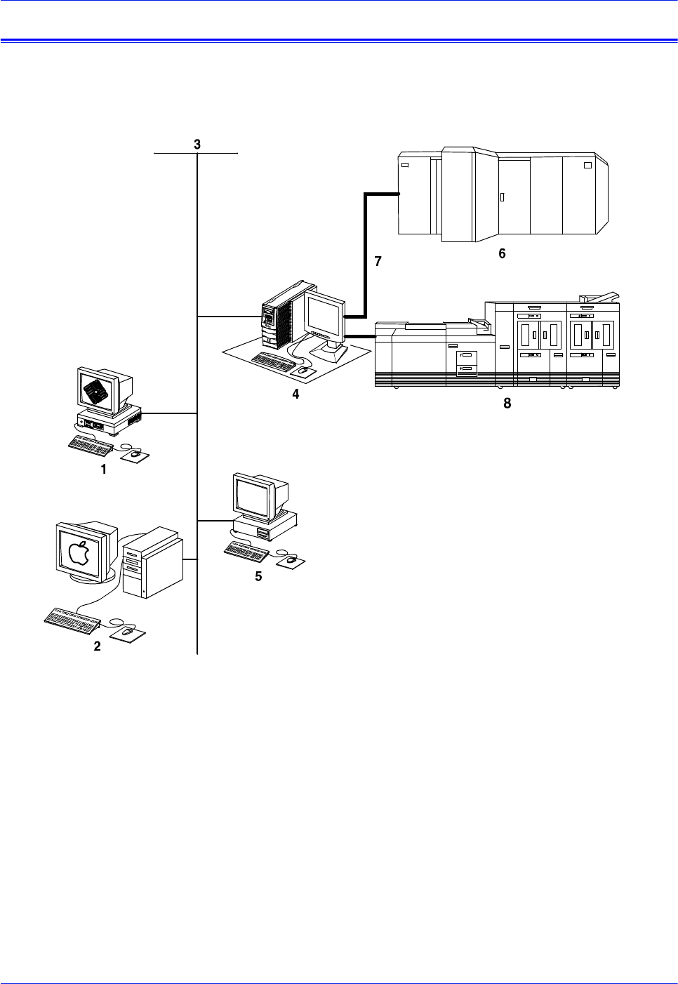
The following figure shows the configurations supported for the
Xerox DocuPrint 100/115/135/155/180 EPS.
Figure 1-1 Configurations supported by Xerox DocuPrint
100/115/135/155/180 EPS
1. Sun UNIX client workstation
2. Apple Macintosh client workstation
3. Network connection
4. Controller
5. PC client workstation
6. Mainframe host computer
7. Bus and tag cables (channel connection)
8. Print engine
The following sections briefly describe the functionality of each
system component.
QTC0702A-SOR

Installation Planning Guide 1-3
Product overview
DocuPrint 100/115/
135/155/180 EPS The DocuPrint 100/115/135/155/180 EPS includes the controller,
printer and all appropriate software. “DocuPrint printer” or “printer”
refers to the base printer engine (IOT) only.
NOTE: Some printer configurations may include a control console
(not shown).
Customer-supplied
client workstation A host mainframe computer or network-connected PC, Apple
Macintosh, or Sun UNIX client workstation submits print jobs to
the printing system. The print job may be in any of the following
data formats:
• PostScript levels 2 and 3
• HP PCL5c, PCL5e, and PCL6: Hewlett-Packard Print Control
Language
• LCDS: Line Conditioned Data Stream
• IPDS: Intelligent Printer Data Stream
• ASCII: American Standard Code for Information Interchange
• PDF: Portable Document Format
• TIFF: Tagged Image File Format
• VIPP: Variable Data Intelligent PostScript Print Ware
NOTE: Enablement of IPDS data format may require additional
equipment. Contact your local Xerox representative for more
information.
Customer-supplied
network and
channel connection
The customer needs to supply one or more of the following
communication connections:
• Ethernet local area network (LAN) running TCP/IP, AppleTalk,
or Novell NetWare network protocol software.
• Online (channel-attached): Bus and tag cables supporting the
IBM 3211/4245 interface.
• Token ring LAN running TCP/IP, Novell 3.x, or AppleTalk
network protocol software.
NOTE: Enablement of channel-attached and Token Ring
communication connection requires additional equipment. Contact
your local Xerox representative for more information.
Xerox-supplied
controller The controller (monitor, processor, DVD drive, keyboard, mouse,
diskette drive, and cartridge tape drive) accepts the print job from
the host mainframe computer or network-connected client
workstation, converts the files into page images, and sends the
page images to the print engine. External 9-track and 18/36-track
tape drives can be used for resource loading and for offline
printing.
Xerox-supplied
printer The printer (also known as the image output terminal [IOT] or print
engine) accepts page image data from the controller and prints
the document according to the print options specified by the user.
The printer also handles paper stacking, collating, and optional
finishing.
1-4 Installation Planning Guide
Product overview
NOTE: It is the responsibility of the customer to supply, install, and
maintain hardware and software on any PC, Sun workstation, or
Macintosh workstation that is used to generate documents for
printing on the DocuPrint 100/115/135/155/180 EPS. You are also
responsible for obtaining, installing, and maintaining the required
Ethernet local area network, transceivers, bus and tag cables, and
any other connecting cables.
The Xerox DocuPrint 100/115/135/155/180 EPS prints LCDS data
from a mainframe host computer, emulating an IBM 4245 or 3211
line printer. The printing system can receive data over a channel
through bus and tag cables and through the Socket Gateway or lpr
using TCP/IP protocol.
Table 1-2 Throughput speed
NOTE: Maximum throughput speed with 7 by 10 inch / 178 by 254
mm paper requires the 7 by 10 inch enablement kit.
Xerox is responsible for the physical installation and service of the
printer and controller hardware and software components. You
have the general responsibility for the site of ensuring that the
correct personnel, supplies, and network hardware and software
are available. Refer to the “Preparing for installation” chapter for a
detailed description of the shared responsibilities of the customer
and of Xerox.
Client workstations and system software
To submit print jobs to the printing system, the customer needs to
provide the proper client hardware as well as operating system
and network software.
Printing
system
Maximum
throughput
speed
Maximum throughput
speed with 7 by 10 inch/
178 by 254 mm paper
DP100 EPS 100 ppm 100 ppm
DP115 EPS 115 ppm 115 ppm
DP135 EPS 135 ppm 154 ppm
DP155 EPS 155 ppm 155 ppm
DP180 EPS 180 ppm 206 ppm

Installation Planning Guide 1-5
Product overview
Supported hardware and operating systems
The Xerox DocuPrint 100/115/135/155/180 EPS supports the
following types of networked client workstations and operating
systems:
• Sun Workstation running Solaris 2.3 or higher
• PC running MS-DOS 5.0 or higher, using Ethernet with TCP/IP
or Novell NetWare 3.11 or higher, Windows 95/98, Windows
NT 4.0, Windows Millennium, Windows 2000, or Windows XP
• PC running MS-DOS 5.0 or higher, with one or more of the
following TCP/IP packages:
– PC/TCP Network Software by FTP Software, Inc.
– Pathway Access by Wollongong Group, Inc.
– PC-NFS by Sun Select
• Apple Macintosh running 8.6 through 9.x, or 10.1 or higher in
Classic mode, using AppleTalk through Ethernet
• Any system that supports RFC-1179 lpr/lpd
The printing system software may be compatible with workstation
models and software versions other than those listed above.
Client networking software
Xerox client software, a third-party TCP/IP lpr networking
software, Novell, or Apple/Macintosh Printer Access Protocol
(PAP) networking software must be installed on your client
workstations or downloaded from the controller. This software
provides an interface with the controller, which allows you to
submit print jobs and check job status.
NOTE: The printing options that are available to a client user vary
according to the networking software loaded on the client
workstation.
Additional information on submitting jobs from a client workstation
is specified in other documents that are part of this publication set.
MICR printing features
The DocuPrint 100/115/135/155/180 MX systems produce a
Magnetic Ink Character Recognition (MICR) line on negotiable
and turnaround documents such as checks and bills. The MICR
printing system prints documents using magnetic ink and special
fonts to create machine readable information that allows for quick
document processing.
1-6 Installation Planning Guide
Product overview
In general, MICR is used to print accounting and routing
information on blank checks and other negotiable documents. The
magnetic encoding capabilities can be used for any printed output.
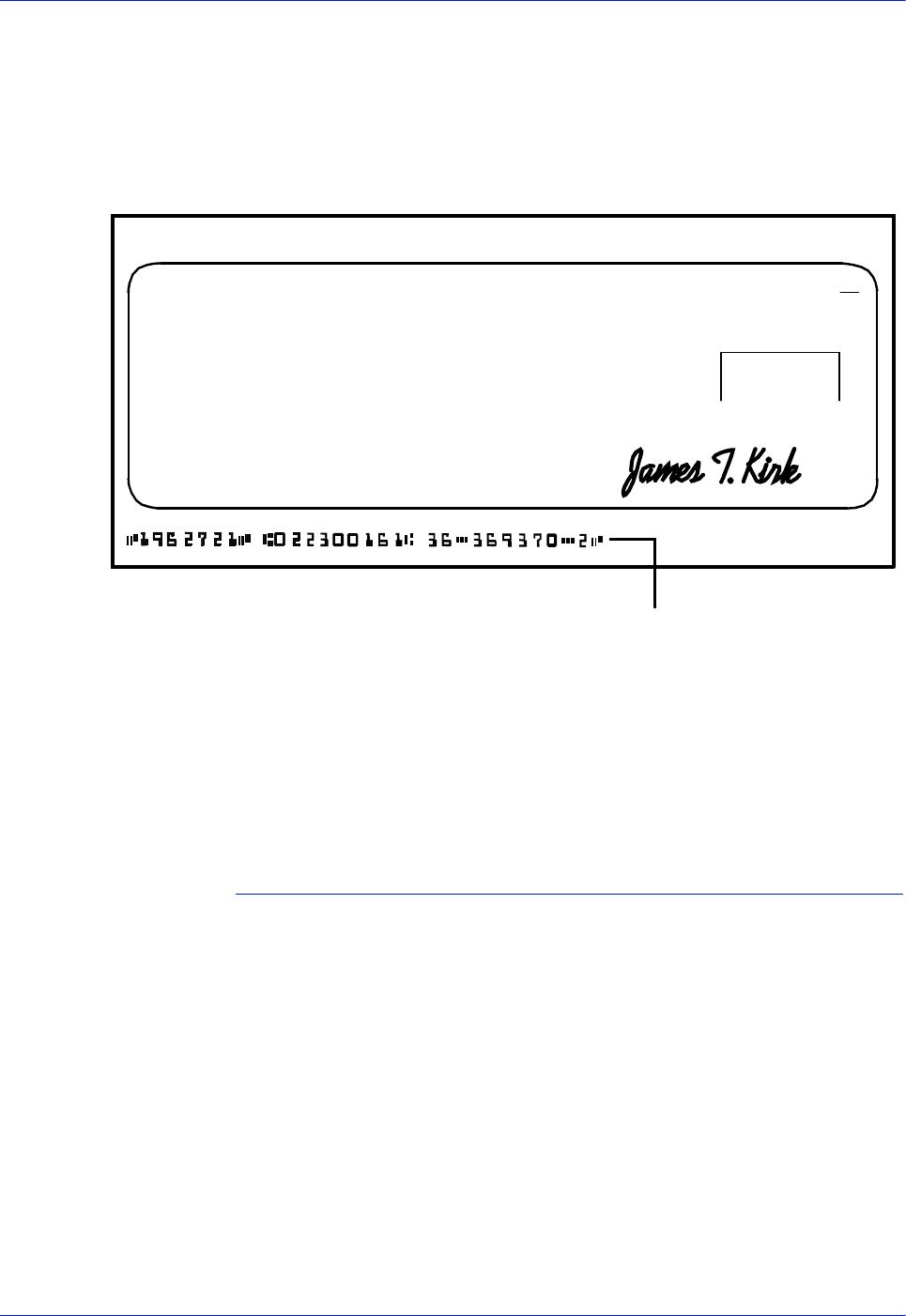
The following illustrates a check printed with a MICR line in U.S.
format. The entire MICR line, which consists of numbers and
characters (called symbols), is printed using magnetic ink.
Figure 1-2 Example of a check printed with MICR line (U. S.)
The DocuPrint 100/115/135/155/180 MX systems meet ABA
standards and ANSI and ISO specifications for automatic check
handling. They print the variable data and the MICR line at the
same time. This single-pass printing capability reduces processing
time and costs.
MICR fonts
Xerox provides a set of 300 and 600 dpi E13B and CMC7 MICR
fonts for use with your DocuPrint 100/115/135/155/180 MX
system. To receive the high print quality guaranteed by Xerox, you
must use these MICR fonts.
CMC7 fonts have been adopted in various countries outside of the
U.S., and are the official standard in France. Like the E13B font,
they are magnetically readable, but with a different character
design and recognition criteria. (Currently, CMC7 is available only
through Xerox Europe.)
MICR fonts The MICR fonts include the following.
E13B fonts:
• E13B
• E13B Landscape
ERA ERA CORPORATION P.O.BOX 9968 KENAN,N.Y.146008
PAY ROLL ACCOUNT
PAYTOTHE ORDER OF
SECURITYTRUST COMPANY OF KENEAN,N.Y.
06-29-84
VOID AFTER 90 DAY S
50-16
223
1962721
$980.28
$* * * *980 28
DOLLARS CENTS
NOT NEGOTIABLE
JEAN L.MAGNIN
484 NORTH PROSPECT
CARUBA BEACH, CA 80297
PAYABLE IF DESIRED AT SOUTHERN PACIFIC
NATIONALTRUST AND SAVINGS ASSOC.
OMAHA, NEBRASKA 12-35/9290
MICR Line

Installation Planning Guide 1-7
Product overview
• E13B Test
• E13B Test Landscape.
CMC7 fonts:
•CMC7
• CMC7 Landscape
•CMC7 Test
• CMC7 Test Landscape
The “Test” fonts are non-readable MICR hollow bitmap (or outline)
fonts, provided for testing MICR applications and printing non-
negotiable documents.
LCDS MICR fonts The MICR fonts that are used for printing an LCDS data stream
include the following.
E13B4 fonts:
• E13B4 Portrait
• E13B4 Landscape
• E13B4 Inverse Portrait
• E13B4J
CMC7 fonts:
• CMC74 Portrait
• CMC74 Landscape
• CMC74 Inverse Portrait
• CMC74J
Unsupported features
The DocuPrint 100/115/135/155/180 EPS does not support the
security and audit feature or bar code reading. In addition,
although the Line Thickening selection and the Virtual Printer
Imaging parameters are available when you use MICR, using
these features when printing MICR documents is not
recommended, as they corrupt the MICR line.
In general, all print quality adjustments and enhancement settings
should be set at the nominal settings when printing MICR output.
Host connectivity options
The Xerox DocuPrint 100/115/135/155/180 EPS can receive data
in the following ways:
• Over a channel through a bus and tag cable connection
• Through a network interface, using Novell, TCP/IP, or

1-8 Installation Planning Guide
Product overview
AppleTalk protocols
Your system may have one or both of these configurations.
Remote Services
Remote Services is a web based application that enables direct
communication between DocuSP and Xerox support. This service
enables:
• Quick resolution of First Call issues
• Automated workflow monitoring
• Real-time trouble-shooting and analysis of print jobs
• Live demonstrations of new product features
For additional information, contact your local Xerox
representative.

Installation Planning Guide 2-1
2 Controller components and
options
This chapter describes the components and options available for
the Xerox DocuPrint 100/115/135/155/180 EPS controller.
Controller overview
The controller receives data from a mainframe host or a
workstation client, processes the data, and sends it to the printer.
The controller also provides the printer with print data and
commands, and receives status information from the printer.
The controller consists of a high performance Sun workstation
processor running Solaris software. Also resident on the controller
is the DocuSP software, which manages all printing, diagnostic,
and administrative functions on the printing system.
The DocuSP software includes a full color graphical user interface
(GUI). Using the GUI, you set up and configure the system, set up
and implement system options, and manage print jobs.
DocuSP remote access
(Remote Workflow) Remote Workflow, a remote graphical user interface, is available
for installation from a CD. The remote GUI allows you to manage
your DocuSP-based printers from a single PC or Sun workstation.
You may set your preferences from the remote client to disable or
enable some or all connections.
Remote Workflow allows you to configure the printers that you
want to manage, and provides real time status of the printers. You
may switch between the printers that you are managing, but you
can display only one printer GUI at a time.
The Remote Workflow GUI looks and functions the same as the
local DocuSP GUI on the controller.
Controller components
The controller consists of a specially-configured Sun workstation
and uses proprietary Xerox hardware, firmware, and software.
Your controller has one of two possible configurations, described
in the following sections.
NOTE: Controller hardware configurations are subject to change,
to keep up with technology advances.
Installation Planning Guide 2-2
Sun workstation
The controller is based on either the Sun Blade 1000/2000, Sun
Blade 2500, or the Sun W1100z workstations with high-
performance architecture for complex processing tasks.
Sun Blade 1000/2000
configuration
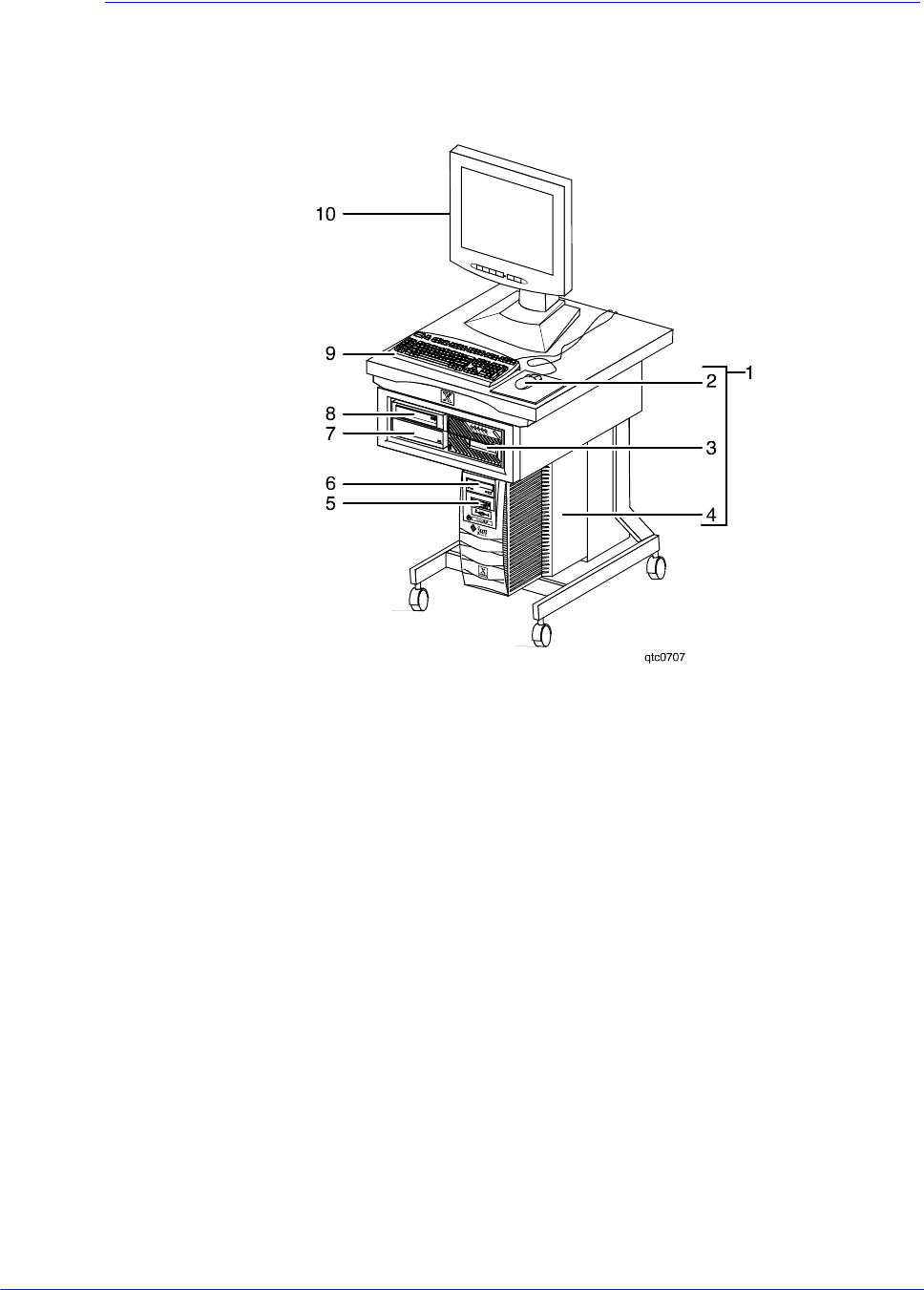
Figure 2-1 Sun Blade 1000/2000 controller
1. Controller stand
2. Mouse
3. 18/36-track cartridge tape drive (optional)
4. Processor
5. Diskette drive
6. CD drive
7. Quarter-inch cartridge (QIC) tape drive
8. External fixed disk drive (optional)
9. Keyboard
10. Display monitor
The Sun Blade 1000/2000 contains the following hardware
components:
• Processor (system unit) containing the following:
– One or two UltraSPARC III high-speed central processing
unit (CPU) modules
• DP 100, 115, and 135: 1 CPU
• DP 155 and 180: 2 CPUs

Installation Planning Guide 2-3
NOTE: In XE, all printers use a dual CPU configuration.
– 1 or 2 GB of memory (one or two 1-GB Dual In-line
Memory Modules, or DIMMs)
• DP 100, 115, and 135: 1 GB
• DP 155 and 180: 1 or 2 GB
NOTE: In XE, all printers use a 2 GB memory
configuration.
– Hard disk drive
• Sun Blade 1000: 36 GB
• Sun Blade 2000: 73 GB
– CD drive
– Diskette drive: uses 3.5 inch, 1.44 MB, double-sided, high-
density diskettes
– Ethernet
– Two Printer Controller Interface (PCI) boards to interface
with the printer
– PGx64 video graphics board
• Universal Serial Bus (USB) keyboard and three-button mouse
• 17-inch flat panel monitor
Installation Planning Guide 2-4
Sun Blade 2500 and
Sun W1100z
configuration
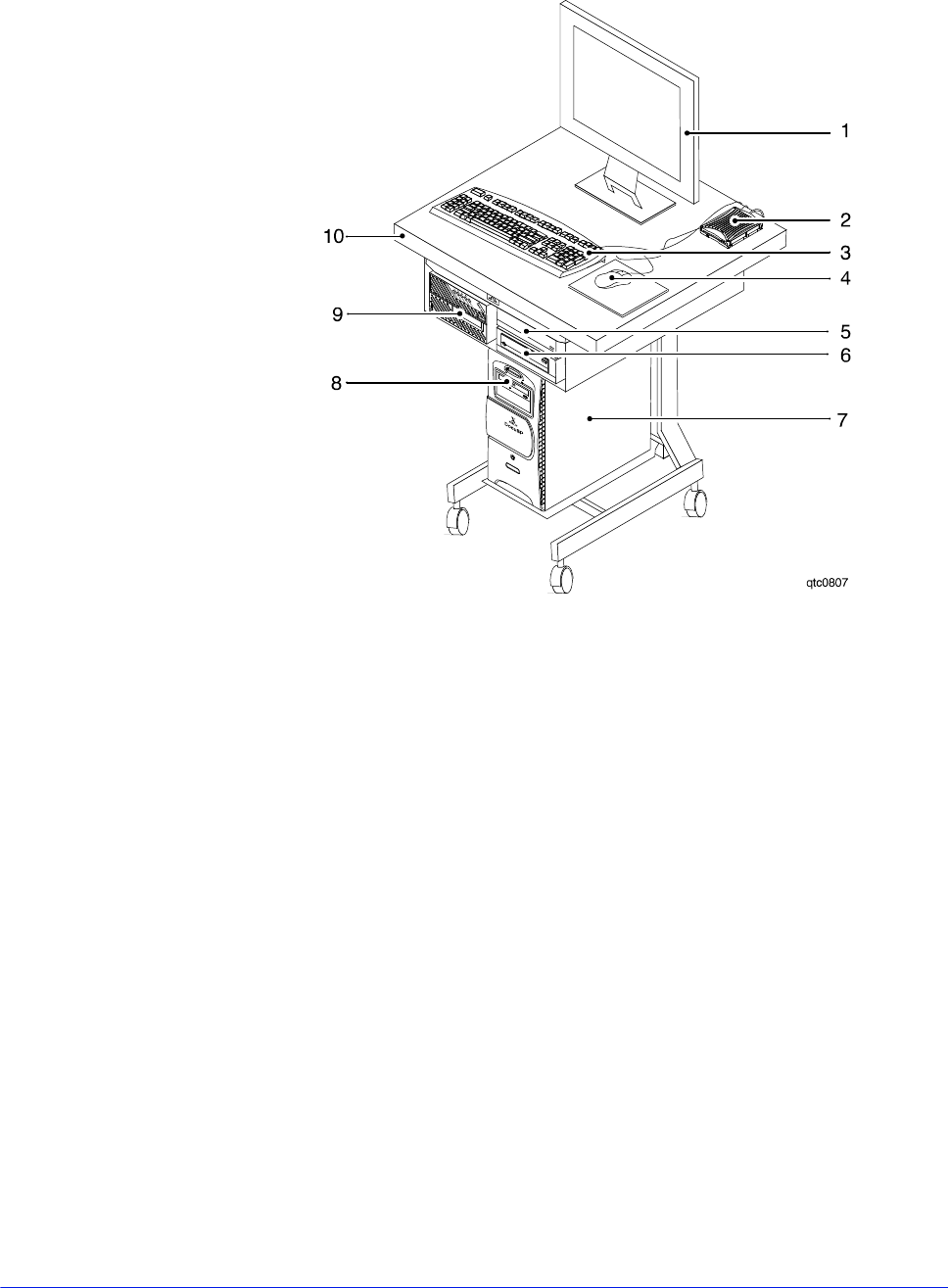
Figure 2-2 Sun Blade 2500 and Sun W1100z controller
1. Display monitor
2. External diskette drive
3. Keyboard
4. Mouse
5. External fixed disk drive (optional)
6. Quarter-inch cartridge (QIC) tape drive
7. Processor
8. DVD/CD-RW drive
9. 18/36-track cartridge tape drive (optional)
10. Controller stand
The Sun workstation contains the following hardware
components:
• Processor (system unit) containing the following:
– One UltraSPARC IIIi high-speed processing unit (CPU)
module
– 1 or 2 GB of memory (one or two 1-GB Dual In-line
Memory Modules, or DIMMs)
• DP 100, 115, and 135: 1GB
• DP 155 and 180: 2 GB

Installation Planning Guide 2-5
NOTE: In Xerox Europe, all printers use a 2 GB memory
configuration.
– 36 GB hard disk drive
– High-density, read-only DVD-ROM drive
– Ethernet
– One or two Printer Controller Interface (PCI) boards to
interface with the printer
• DP 100, 115, and 135: 1 board
• DP 155 and 180: 2 boards
– XVR-100 video graphics board
• Universal Serial Bus (USB) keyboard and three-button mouse
• 17-inch flat panel monitor
• Diskette drive (external)
Processor The central processing unit contains the memory, internal disk
drive, a graphics board, a DVD/CD-RW drive, a diskette drive,
power receptacle and outlet, connectors and ports.
•Memory: Two 1 GB Dual In-line Memory Modules, or DIMMs,
are provided as a standard feature of the processor.
•Hard disk drive: A 36 or 73 GB primary disk drive is provided
as a standard feature of the processor. The operating system,
the NPS/IPS application, and any queued print jobs are stored
on the internal disk. This disk cannot be used to store other
applications or data except as directed by your service
representative.
•CD drive: The CD drive is a high density, read-only, optical
laser storage device used for loading the NPS/IPS operating
system and other files. The CD-ROM drive is located in the
processor above the diskette drive.
2-6 Installation Planning Guide
Controller components and options
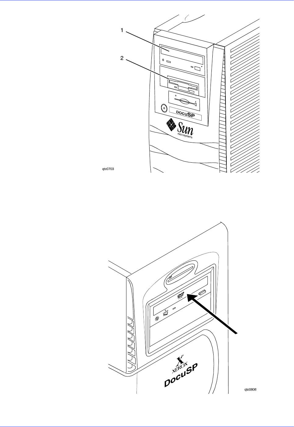
Figure 2-3 Drive locations on the Sun Blade 1000/2000 processor
1. CD drive
2. Diskette drive
Figure 2-4 DVD/CD-RW drive location on Sun Blade 2500 and Sun
W1100z processor
Installation Planning Guide 2-7
Controller components and options
•Back panel: The back panel of the processor has a power
receptacle and outlet, connectors, connector openings, and
ports. The following figure shows the back panel of the
controller.
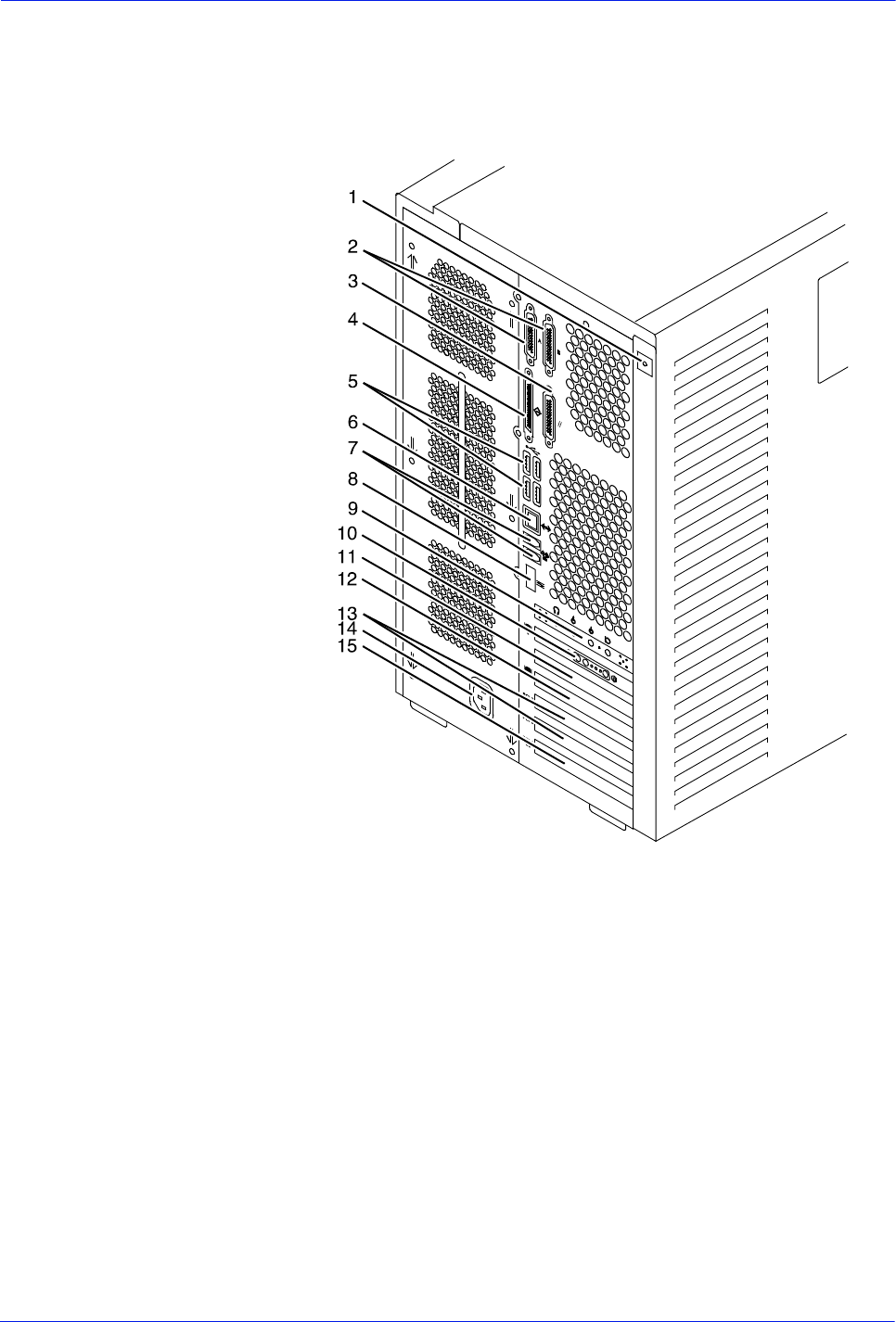
Figure 2-5 Back panel of the Sun Blade 1000/2000 controller
1. Access panel lock block
2. Serial connectors A and B, DB-25
3. Parallel connector
4. SCSI connector
5. Universal serial bus (USB) connectors
(for keyboard and for mouse)
6. Twisted-pair Ethernet (TPE) connector
7. IEEE 1394 connectors
8. Fibre Channel-Arbitrated Loop (FC-AL) connector
9. Audio module headphones, line-in, line-out, and
microphone connectors
10. Graphics card / video connector (frame buffer 0)
11. PCI card slot 4
12. Graphics card / video connector (frame buffer not used)
13. PCI card slots 3 and 2
14. Power connector
15. PCI card slot 1
2-8 Installation Planning Guide
Controller components and options
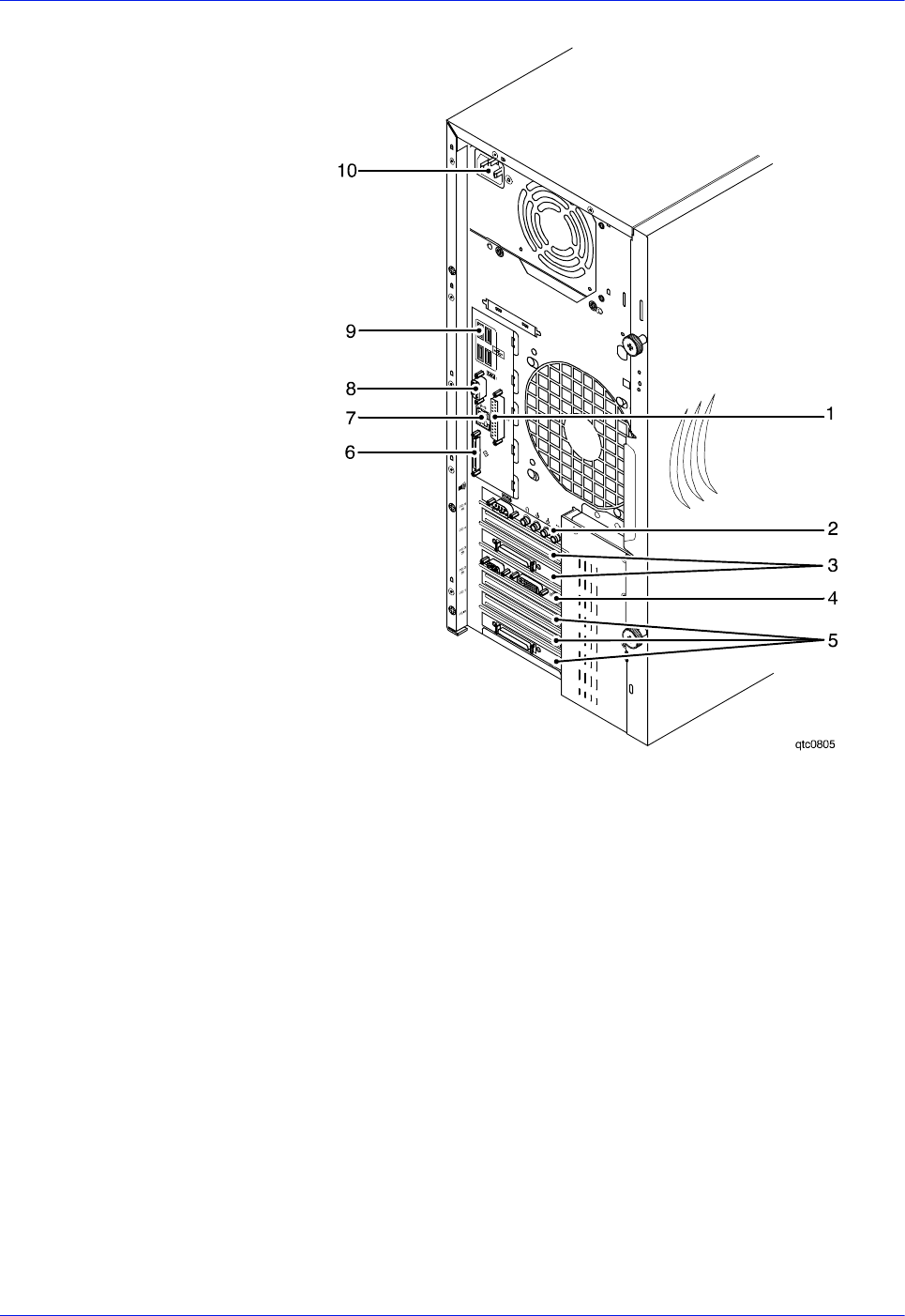
Figure 2-6 Common back panel of Sun Blade 2500 and Sun W1100z
1. Parallel connector
2. Audio module headphones, line-in, line-out, and
microphone connectors
3. PCI card slots 4 and 5
4. Graphics accelerator
5. PCI card slots 0, 1, and 2
6. External UltraSCSI connector
7. Twisted-pair Ethernet
8. Serial connector
9. USB connectors (The diskette drive may be plugged into
any one of these.)
10. Power connector
Keyboard The keyboard consists of alphanumeric keys similar to a
typewriter, symbols and special character keys, an extended
character set, and function keys. The keyboard is one of your
main methods of communicating with the printer. You can use the
keyboard to make selections, and to enter commands that control
functions such as requesting sample prints, or shutting down the
system.

Installation Planning Guide 2-9
Controller components and options
Mouse The mouse is another main method of communicating with the
printer.
Display monitor The 17-inch LCD monitor allows you to interact with the printer
and to monitor its interaction with the various components. During
a print job, printer error messages may display to notify you of any
unexpected conditions.
Diskette drive The external diskette drive plugs into the back panel of the
processor. Diskettes inserted into a diskette drive are used to
install fonts and to load files to, and back up files from, the internal
disk drive. The diskette drive uses industry standard 3.5 inch, 1.44
MB, double-sided, high-density diskettes.
Optional processor
components The controller may be configured with any of the following optional
components:
• Connectivity board to enable Token Ring
• Channel interface board for channel connection to a host for
online LCDS printing
• One SCSI board to connect to an external tape drive
• Graphics board:
– PGx64 (Sun Blade 1000/2000)
– XVR-100 (Sun Blade 2500)
– Creator-3D series 3 graphics board
NOTE: The PGX64 graphics board is provided as a standard
feature of the processor. If more than one connectivity option is
installed, the PGx64 board is replaced by the Creator3D graphics
board.
Controller interface options
Your printing system may be configured for either the online
interface, the offline interface, or both.
Online interface
The online (channel-attached) interface receives input directly
from any environment that supports the IBM 3211 and 4245 host
systems.
2-10 Installation Planning Guide
Controller components and options
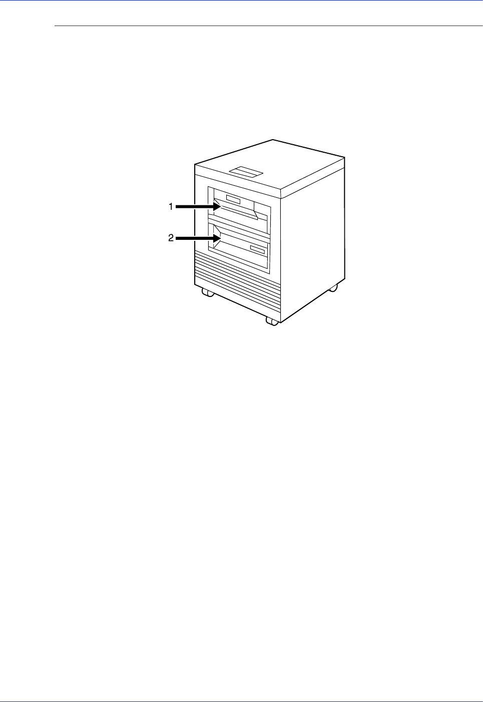
Tape drive option
The 36-track cartridge tape drive is an option. Your printing
system supports the following tape drives for offline printing and
importing and exporting of resources:
• 9-track open reel tapes
• 36-track cartridge tapes
Figure 2-7 Peripheral cabinet with tape drives
1. 9-track open reel tape drive
2. 18/36-track cartridge tape drive
If you have other Xerox printing systems, you may already have a
peripheral cabinet that houses a 9-track open reel and an 18/36-
track cartridge tape drive. The DocuPrint 100/115/135/155/180
EPS supports existing peripheral cabinets, but the peripheral
cabinet option is not available with new systems.
The following 18-track tape drives are not supported:
• STK 4220 MOD 1 tape drive (3480)
• STK 4220 MOD 2 tape drive (3490)
Installation Planning Guide 3-1
3 Printer components and
options
The printer processes the page images received from the
controller and produces the printed output. This chapter describes
the components and options available for the Xerox DocuPrint
100/115/135/155/180 EPS printer.
Printer components
The standard printer components are the sample tray, the purge
tray, the two processor feeder trays, and the feeder/stacker
module or modules.
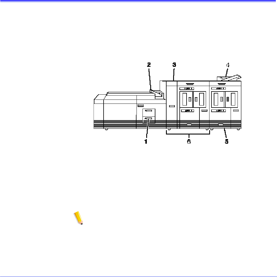
The base configuration for the printer includes an inverter feeder/
stacker and one additional feeder/stacker module.
Figure 3-1 Printer base components
1. Processor feeder trays
2. Sample tray
3. Attention light
4. Purge tray
5. Feeder/stacker module
6. Inverter feeder/stacker module
NOTE: Some printer configurations may include a control
console (not shown).
The printer provides control buttons and displays for basic printer
functions and status information. Where available, the printer
control console displays messages and graphics that assist you
with jam clearance and printer maintenance. Labels are located
3-2 Installation Planning Guide
Printer components and options
throughout the printer to assist you with a variety of tasks such as
clearing a paper jam.
Refer to the Xerox DocuPrint 100/115/135/155/180 Enterprise
Printing System Operator Guide for detailed description of the
features and operation of the printer components.
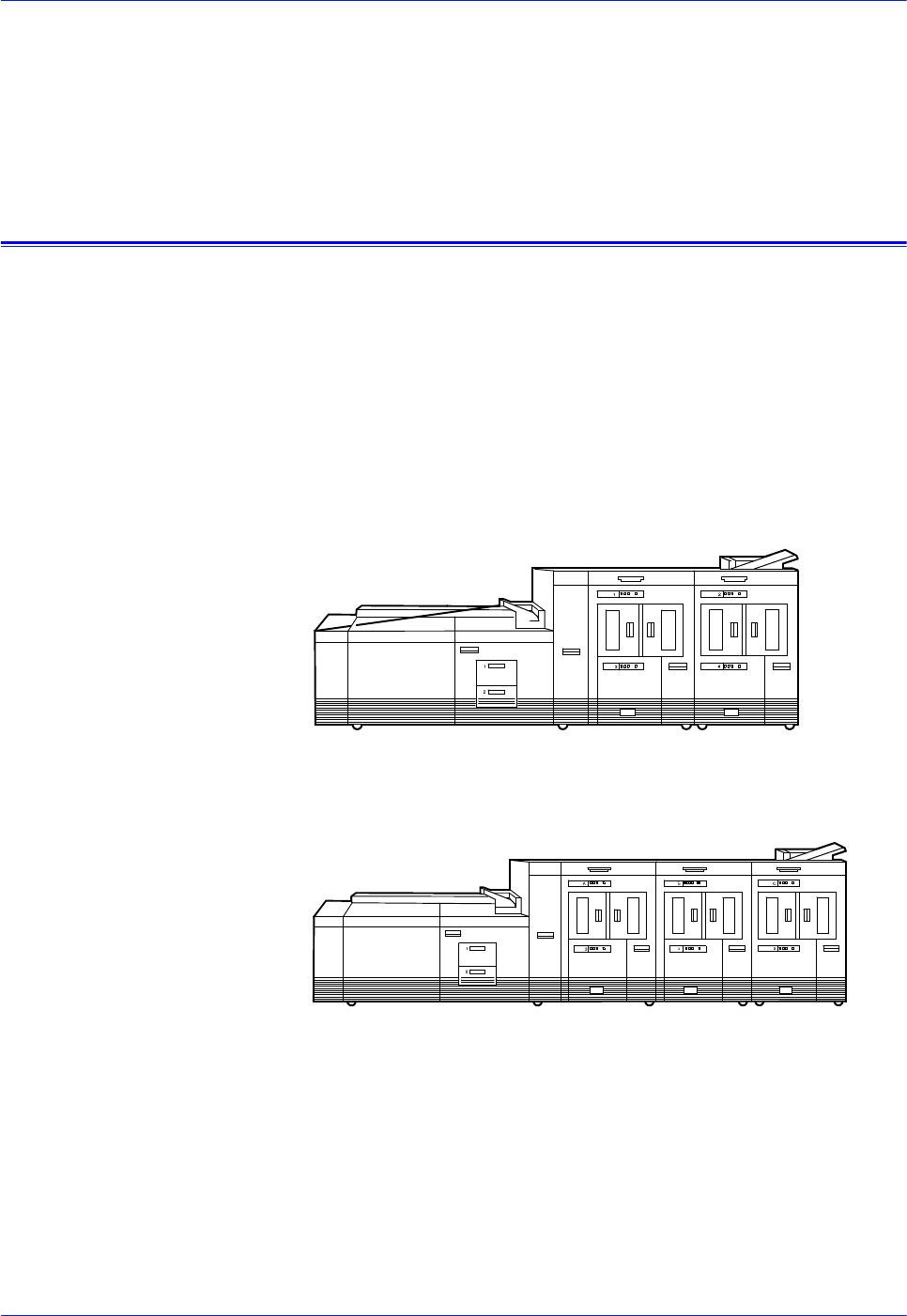
Printer configurations
The Xerox DocuPrint 100/115/135/155/180 EPS is available in
several different configurations, which allow you to customize the
printing system for increased efficiency and for specialized
applications.
• Inverter feeder/stacker + 1 feeder/stacker
• Inverter feeder/stacker + 2 feeder/stackers
• Inverter feeder/stacker + 3 feeder/stackers
These configurations are illustrated below.
Figure 3-2 Printer with inverter feeder/stacker and
one feeder/stacker
Figure 3-3 Printer with inverter feeder/stacker and
two feeder/stackers
Installation Planning Guide 3-3
Printer components and options
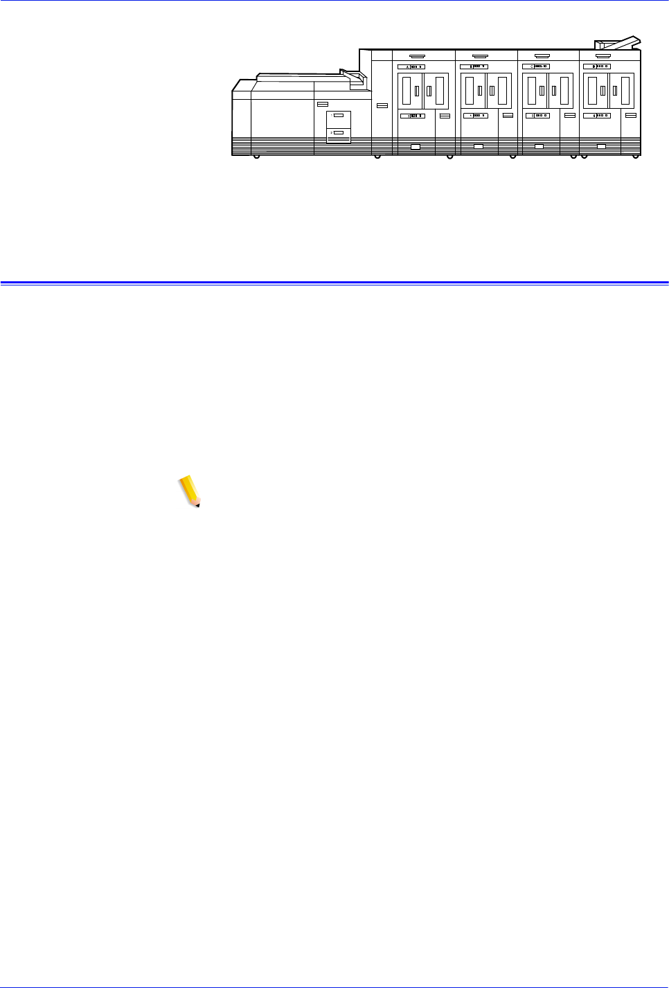
Figure 3-4 Printer with inverter feeder/stacker and
three feeder/stackers
Bypass transport option
The bypass transport option provides an interface between the
DocuPrint 100/115/135/155/180 EPS and your finishing
accessories. However, finishing devices require separate power
sources that are independent of the printing system.
The bypass transport option enables third party finishing devices
to interface directly with the printing system. The bypass transport
allows you to customize your printer for increased efficiency and
specialized applications involving finishing.
NOTE: A bypass transport must be installed for the printing
system to support a third party finishing device.
Function of the
bypass transport Connected to the last feeder/stacker module, the bypass transport
moves paper from the stacker to a third party finisher such as a
stitcher, booklet maker, tape binder, and so on. By making
selections on the user interface windows, you can program the
printer to send output to the bypass transport, which directs the
output to the finishing equipment.
Paper stocks
supported on
bypass transport
The bypass transport accepts all paper stocks on which the printer
can print, and it accommodates simplex and duplex printing.
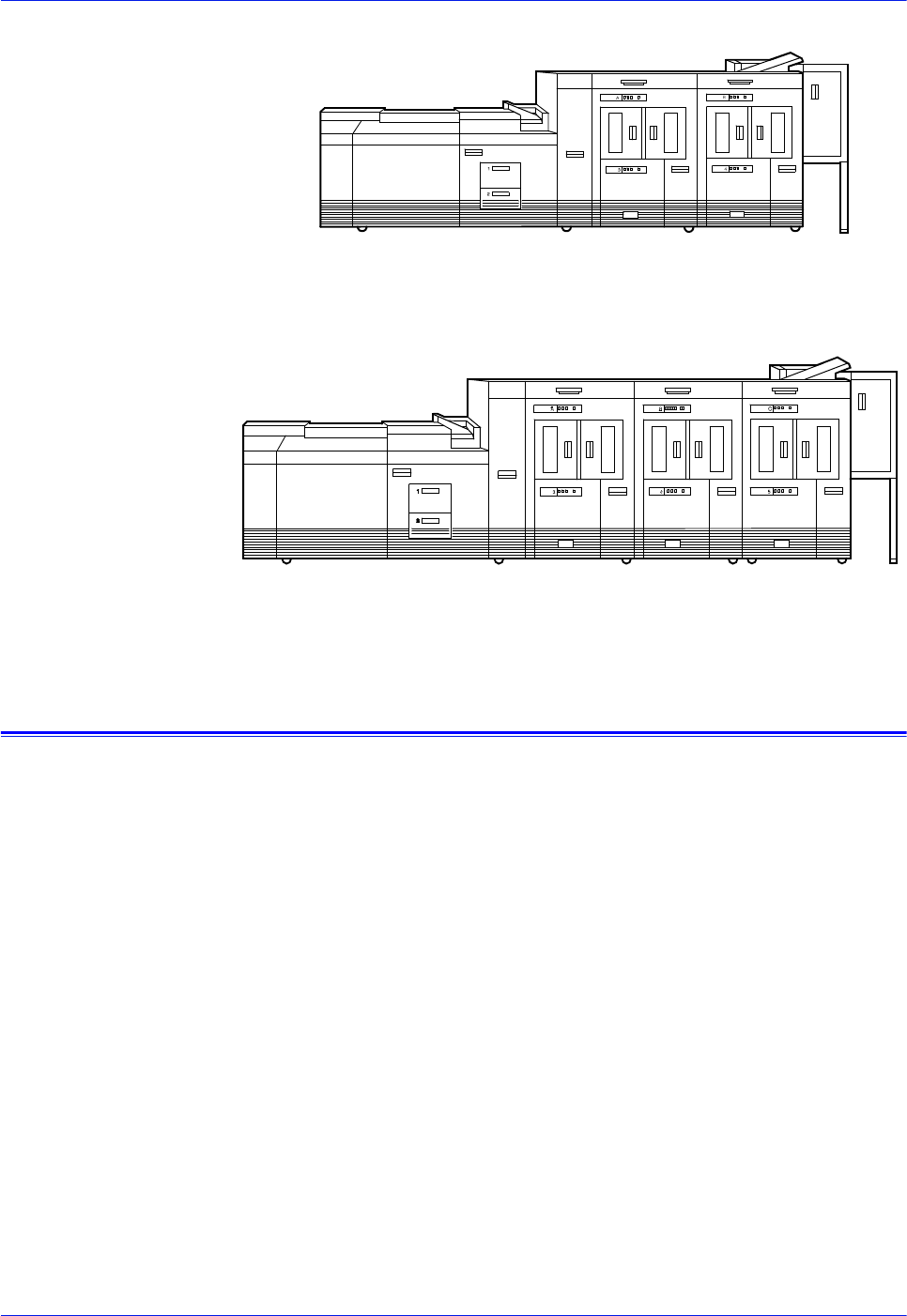
Bypass transport
printer
configurations
The following printer configurations may have the bypass
transport, illustrated below:
• Printer with inverter feeder/stacker and 1 feeder/stacker
• Printer with inverter feeder/stacker and 2 feeder/stackers
3-4 Installation Planning Guide
Printer components and options
Figure 3-5 Printer with inverter feeder/stacker,
one feeder/stacker, and bypass transport
Figure 3-6 Printer with inverter feeder/stacker,
two feeder/stackers, and bypass transport
Roll feeder support (DP155 and DP180 EPS only)
The roll feeder option may be installed in the inverter feeder/
stacker module, replacing the feeder tray. This option does not
require DFA or input enablement software, or any additional
hardware.
The maximum number of feeder/stacker modules supported for
this configuration is four, including the inverter module with the roll
feeder. With the two processor feeder trays, this makes a total of
six input trays possible.

Installation Planning Guide 4-1
4 Preparing for installation
This chapter assists you in preparing for the installation of your
Xerox DocuPrint 100/115/135/155/180 EPS. Use this chapter in
conjunction with the Getting Ready for Installation manual.
Preparing for installation is a responsibility shared by personnel at
your site and Xerox. Your Xerox representatives are available to
discuss installation issues and to assist you in completing the site
installation tasks.
Before installation, you must select and prepare an appropriate
location for the printing system and order supplies. This chapter
helps you accomplish these tasks by providing the following
information:
• A summary of your responsibilities and those of your Xerox
service representative
• A checklist of installation planning activities.
For information on controller power and space requirements, refer
to the “Controller specifications and requirements” chapter of this
guide. For facts about printer power and space requirements,
refer to the “Printer specifications and requirements” chapter of
this guide.
Responsibilities
This section describes your site responsibilities and the
responsibilities of your service representatives. Some joint
responsibilities are included.

4-2 Installation Planning Guide
Preparing for installation
Xerox responsibilities
This section lists the responsibilities of the service representatives
and systems analysts before, during, and after installation:
• Site selection
– Assist in site selection
– Inspect and approve the site
• Installation
– Schedule the delivery of the hardware
– Monitor installation activities
– Assist you in ordering any supplies required
– Install the printing system
– Install LCDS system resource files, if applicable
•Training
– Provide initial operator training
– Provide information and assistance in registering for Xerox
Customer Education classes
• Service
– Review preventive maintenance schedules and service
call procedures
– Provide ongoing maintenance
– Assist in resolving hardware and software problems
– Obtain software licenses as appropriate
Customer responsibilities
Your responsibilities before, during, and after installation of the
DocuPrint printing system are to schedule and monitor your
installation activities. Refer to the installation planning checklist in
this chapter for a complete list of responsibilities.
Refer to the “Xerox support services” appendix for information on
services designed to support you before, during, and after your
installation.
NOTE: Operating system software is not the same for all printing
systems. Therefore, make sure that your system specialists are
familiar with the operating system software that is specific to your
DocuPrint system. If your system specialists are familiar with one
operating systems and you are converting to, or adding another,
they should be familiar with the differences.
Site personnel Identify the person (or persons) at your site who will be the
primary interface with Xerox.

Installation Planning Guide 4-3
Preparing for installation
After the installation of the printing system, there are a few
ongoing tasks that must be performed. These tasks may include
all or some of the following:
• Meter reading and reporting
• Overseeing routine maintenance
• Placing service calls for hardware problems
• Ordering additional documentation, software, or fonts
• Arranging additional operator training
• Maintaining an adequate inventory of consumable supplies.
It is your responsibility to designate a person (or persons) to
perform these tasks.
Operator and
systems training Select personnel for operator and systems training and set up a
training schedule.
Site preparation Select and prepare the site for system installation (including
proper power, air conditioning, and work space). If connecting to
other equipment, obtain the necessary interfaces, cables,
transceivers, phone lines, and so forth.
Network installation Install the necessary network components required to connect
client workstations to the printing system. Refer to the Getting
Ready for Installation manual for details.
Channel-attached
printing Obtain and install fully populated bus and tag cables required to
connect the host to the printing system. Refer to the Getting
Ready for Installation manual for details.
Client workstations Make sure all client workstations that will be submitting print jobs
have the proper hardware, operating system, and networking
software required by the printing system as client platforms.
Applications Work with your Xerox systems analyst to determine requirements
for initial applications.
Installation planning checklist
To aid you in planning for printer installation, the following
checklist contains the tasks that you and your service
representative must complete before installation. If you have
questions about any of these activities, contact your sales or
service representative.
Use the time frames in this checklist as guidelines. It is best to
consult your suppliers to determine the required lead times.

4-4 Installation Planning Guide
Preparing for installation
Table 4-1 Installation planning checklist
Week Activity Responsibility Date
completed
-4 • Select location for the printing system.
• Order additional sets of documentation, as
necessary.
• Register for Xerox Customer Education classes
and order tutorials, as necessary.
• Schedule printer delivery.
Customer
Customer
Customer and Xerox
Xerox
_________
_________
_________
_________
-3 • Schedule hardware delivery.
• Prepare site:
• Ensure proper electrical outlets are installed.
• Install network to system location, if applicable.
• Install channel to system location, if applicable.
Cables must be fully populated.
• Ensure proper operating environment.
Customer and Xerox
Customer
_________
_________
_________
_________
_________
-2 • Inspect and approve site.
• Order consumable supplies. Minimum supplies
needed for installation:
• Paper (2 cartons)
• Developer (1 carton)
• Fuser agent (2 boxes)
• Dry ink (1 carton)
• After installation, you will need to establish a
procedure for ordering supplies according to
your ongoing production requirements.
Xerox
Customer and Xerox
_________
_________
-1 • Schedule operator training. Customer and Xerox _________
Install Ensure supplies are available.
Ensure system administrators are available during
software installation.
Provide applicable completed worksheets from the
Getting Ready for Installation document.
If the NPS/IPS Extension option is being installed,
provide applicable information as directed in the 96/
4635/180 NPS/IPS Installation Planning Guide.
Install printing system hardware and software.
Have operators available for training.
Check documentation and software kits for
completeness.
Have test jobs ready to run.
Provide stocks needed for default input
configuration.
Obtain and enable software license.
Customer
Customer
Customer
Xerox
Customer
Customer
Customer
Customer
Customer
_________
_________
_________
_________
_________
_________
_________
_________
_________

Installation Planning Guide 4-5
Preparing for installation
.
Connectivity requirements
An Ethernet local area network (LAN) running Transmission
Control Protocol/Internet Protocol (TCP/IP), AppleTalk, or Novell
NetWare software is the network communication system used to
transport documents from the client workstation to the printing
system.
Ethernet specifications
The Ethernet connection to the controller processor must be
compatible with the Institute of Electrical and Electronics
Engineers (IEEE) 802.3 standard.
The Ethernet interface on the controller processor is a 10 Mb/sec
twisted pair standard (10BaseT, 100BaseT, and 1000BaseT).
Attachment Unit Interface (AUI) Coax Ethernet is enabled with an
adapter cable.
Work with your system administrator to assess what type of
network you have and what modifications need to be made to
supply an Ethernet connector to the controller processor.
Token Ring specifications
Users of network client workstations may send print jobs to the
printer using TCP/IP, Novell 3.x, or Apple Talk network protocol.
The Token Ring connection to the controller processor must be
compatible with the Institute of Electrical and Electronics
Engineers (IEEE) 802.3 standard.
The controller processor has a 4 MB or 16 MB Token Ring Auto
interface (16 MB is preferred).
Post-install Become familiar with support services available.
Establish supplies maintenance procedure.
Provide ongoing system maintenance.
Adjust the printer alignment and magnification.
Order additional documentation, as necessary.
Customer
Customer
Customer and
Xerox
Xerox
Customer
_________
_________
_________
_________
_________
Week Activity Responsibility Date
completed

4-6 Installation Planning Guide
Preparing for installation
Channel-attached specifications
For an online configuration with an IBM host system, the following
cables must be available:
• Bus and tag cables (bus in, bus out, tag in, tag out)
• Terminators (as necessary, due to location on channel).
For your convenience, you may be able to order the bus and tag
cables through Xerox on a purchase-only basis. Contact your
Xerox sales representative for availability, current pricing, and
order information.

Installation Planning Guide 5-1
5 Controller requirements
and specifications
This chapter provides power and space requirements for the
controller. It also provides controller environmental specifications.
For facts about printer power and space requirements, refer to the
“Printer specifications and requirements” chapter of this guide.
Power requirements
Your controller has important power requirements that must be
accommodated. These requirements are summarized in the table
below.
For details on printer power requirements, refer to the “Printer
specifications and requirements” chapter of this guide.
Table 5-1 Controller electrical requirements
Table 5-2
Agency certification: UL 1950, IEC 950, CSA 22.2 #950-1950,
FCC (Class A), and EN 55022: 1998 (Class A), and EN 61000-3-2
(or EN 61000-4-2,3,4,5,6,8,11): 1995 + A1-1998 + AZ 1998,
EN6100-3-3: 1995 and EN 55024: 1998.
Outlet configurations
This section discusses specifications for system outlets and the
required wall outlet configurations for the USA / Canada and
internationally.
Sun and
Sun Blade
controller Voltage Amp service KVA rating NEMA
60 HZ 100 to 240
VAC
15 amp 0.4 KVA 5-15R
50 HZ 100 to 240
VAC
15 amp 0.4 KVA N/A
5-2 Installation Planning Guide
Controller requirements and specifications
NOTE: All power outlets must be dedicated to this equipment.
When determining the electrical connections for printing system,
make sure that:
-Each power cord has a separate circuit.
-The printer power cord configurations match your receptacle.
-Your electrical outlets are within the required specifications.
50 Hz systems: Ensure that power connections are per local
codes/regulations.
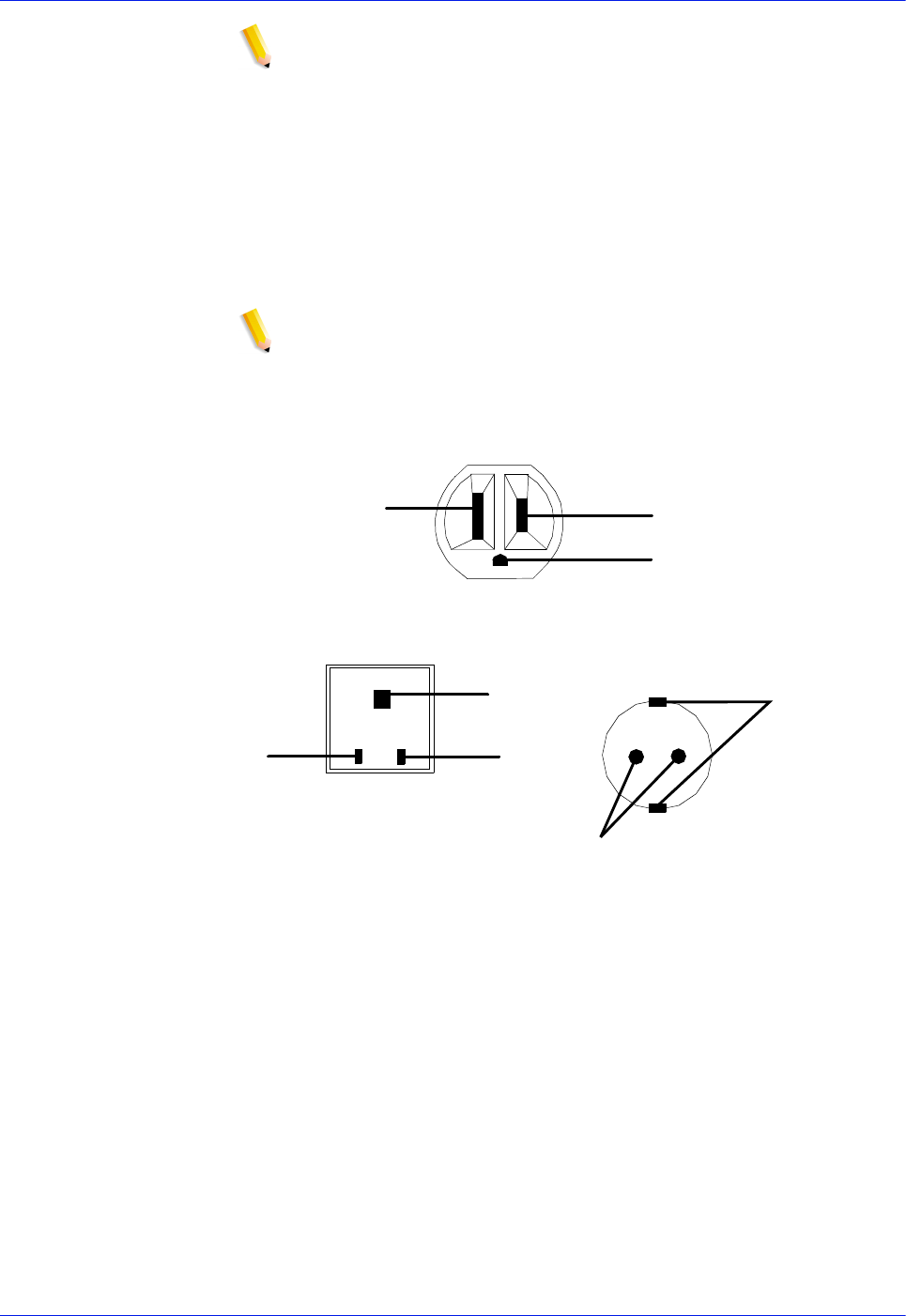
The following figure shows American, Canadian, and European
wall outlets in which to plug the controller.
NOTE: The optional 9 track and 18/36 track tape drives each
require an outlet identical to the one that is shown for the
controller.
Figure 5-1 Multinational wall outlet configurations
The required wall outlet voltages for USA / Canada, United
Kingdom, and the rest of Europe are as follows:
•USA / Canada: The voltage at the wall outlet is 100 to 120
VAC between AC hot and neutral, and between AC hot and
GND. The voltage is less than three VAC between GND and
neutral.
•United Kingdom: The voltage at the wall receptacle is 200 to
240 VAC between live and neutral, and between live and
earth. The voltage is less than three VAC between earth and
neutral.
•Europe: The voltage at the wall receptacle is 200 to 240 VAC
between supply pins. The voltage between one supply pin and
AC Hot (ACH)
Earth Ground (GND)
AC Neutral
(ACN)
United Kingdom
Earth
Live
N
eutral
USA/Canada
Earth
Supply
Europe

Installation Planning Guide 5-3
Controller requirements and specifications
earth is 200 to 240 VAC. The voltage between the other
supply pin and earth is less than 3 VAC.
Refer to the controller electrical requirements table earlier in this
chapter for a description of the power specifications for the
controller.
WARNING: To reduce the risk of electrical shock, do not plug
components into any other type of power system. Contact your
facilities manager or a qualified electrician if you are not sure what
type of power is supplied to your work area.
Environmental specifications
The controller is a sturdy piece of equipment; however, like any
piece of electronic equipment, it must be treated properly. Avoid
extremes in temperature and other environmental hazards. Place
the controller in a relatively dust-free area that is well-ventilated to
avoid overheating.
In general, if your working environment is comfortable for you, it is
suitable for your controller. The following sections define the
acceptable environmental ranges for the controller models with
which your system may be configured.
For recommended environmental ranges for the printer work area,
refer to the “Printer specifications and requirements” chapter of
this guide.
Space requirements
This section provides recommendations for placement of
controller hardware components.
For printer component space requirements, refer to the “Printer
specifications and requirements” chapter of this guide. Contact
your service representative if you have questions not specifically
addressed in this guide.
Controller placement
WARNING: The controller must be positioned within the line-of-
sight of the printer for safety purposes while servicing the
equipment.
The controller components are placed in the accompanying
controller stand. You should consider the following factors when
deciding where to place the controller and stand:
• There should be at least 36 inches / 15.2 cm of clearance on

5-4 Installation Planning Guide
Controller requirements and specifications
all sides of the controller stand.
• Adequate work space and service clearance around the
equipment
• Proximity to electrical and network connectors
• Security of the work area. You may need to place the system
in an area where you can restrict access to it.
Guidelines for controller placement
To ensure consistent performance and avoid any damage to
equipment, follow these rules for placing the components of the
controller.
Do:
• Use the controller stand that comes with your printing system
equipment.
• Allow at least 6 inches / 152 mm of unobstructed space at the
front and rear of the processor, so the fan and vents are not
blocked.
The following illustration shows fan and vent locations on the
front and back of the processor.
Do not:
• Place the monitor and processor on a desk or table top.
• Do not place the monitor on top of the processor.
• Do not allow any piece of equipment to blow warm air into the
air intake vents of the processor.
• Do not place the processor on its side, or in any other position
but the upright, vertical position achieved by using the
controller stand.
• Do not place the processor or monitor on top of the printer.
Controller hardware specifications and requirements summary
For a summary of printer hardware specifications and
requirements, refer to the “Printer specifications and
requirements” chapter of this guide. Contact your local Xerox
representative if you have questions not specifically addressed in
this guide.

Installation Planning Guide 6-1
6 Printer requirements and
specifications
This chapter provides power and space requirements for the
DocuPrint 100/115/135/155/180 EPS printer. It also provides
printer environmental specifications.
For information about controller power and space requirements,
refer to the “Controller specifications and requirements” chapter of
this guide.
Power requirements
Your printer has important power requirements that must be
accommodated. These requirements are summarized in the table
below.
For further details on power requirements, refer to the voltage
charts and wiring diagrams that follow.
For details on controller power requirements, refer to the
“Controller specifications and requirements” chapter of this guide.
Table 6-1 Printer electrical requirements
Agency certification: UL 478 and 1950, IEC 950, CE Mark,
CSA 22.2 #220-1986, FCC (Class A), and VDE 0871 (Class A).
Component Voltage Amp. service KVA rating
(operating mode) Additional
Requirements
Printer 60 Hz
(U.S. and
Canada)
120/240 VAC or 120/
208 VAC (Cord 1)
120/240 VAC or 120/
208 VAC (Cord 2 for DP
155 and DP180 only)
50 amp (Cord 1)
30 amp (Cord 2 for
DP 155 and DP180
only)
Operating: 7.3
+ .75 per middle
module stacker
14-50R (Cord 1)
14-30R (Cord 2
for DP 155 and
DP180 only)
Printer 50 Hz -
WYE (Star) 380, 400, 415 VAC
(3 phase, 5 wire) 30 amp Consult local
service
representative
6-2 Installation Planning Guide
Printer requirements and specifications
Outlet configurations
This section discusses specifications for printer outlets and the
required wall outlet configurations for the USA / Canada and
internationally.
NOTE: All power outlets must be dedicated to this equipment.
When determining the electrical connections for your printer, make
sure that:
a) Each power cord has a separate circuit
b) The printer power cord configurations match your receptacle
c) Your electrical outlets are within the required specifications
50 Hz systems: Ensure that power connections are per local
codes/regulations.
60 Hz printer outlet voltages
The following table shows the voltages for the outlets on your
printer. All power outlets must have a dedicated circuit for each
system equipment piece. Make sure each power cord has a
separate circuit.
Table 6-2 Printer (60Hz) voltage requirements at power outlet
Printer power outlet
and cord voltage
configurations–
60 Hz
The following figures shows the 60 Hz power outlet configuration
for 50 amp NEMA 14-50R and 30 amp NEMA 14-30R. Voltage to
ground is shown for troubleshooting purposes.
Service outlet
configuration Measurement of
wiring Nominal Range
4 Wire Line 1 to neutral 120 V RMS 107-127 V RMS
4 Wire Line 2 to neutral 120 V RMS 107-127 V RMS
4 Wire Neutral to ground 00-10 V RMS
4 Wire Line 1 to line 2 208 V RMS 182-220 V RMS
4 Wire Line 1 to line 2 240 V RMS 210-254 V RMS
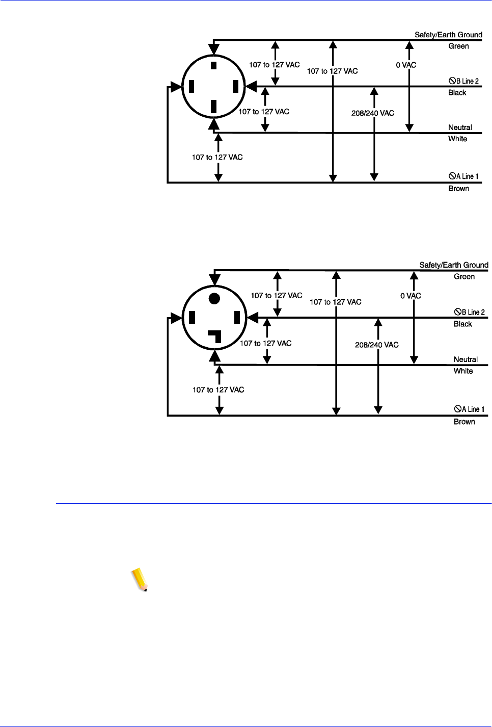
Installation Planning Guide 6-3
Printer requirements and specifications
Figure 6-1 60 Hz power configuration–50 amp
Figure 6-2 60 Hz power configuration–30 amp
50 Hz printer outlet voltages
All power outlets must have a dedicated circuit for each system
equipment piece. Make sure each power cord has a separate
circuit.
NOTE: Consult with your service representative to ensure that the
installation conforms to your local electrical requirements.
WYE (or Star)
configurations–
50 Hz
For the 50 Hz WYE configuration, measure the WYE or Star
connection voltages at the power source.
NEMA
14-50R
NEMA
14-30R

6-4 Installation Planning Guide
Printer requirements and specifications
Table 6-3 Printer (50 Hz) WYE (Star) 415 voltage
The following lists the 50 Hz WYE/Star printer outlet information
for 380 and 400 volts.
Table 6-4 Printer (50 Hz) WYE (Star) 380 and 400 voltage
Printer power outlet/
cord voltage
configurations–
50 Hz
For 50 Hz systems outlet/power cord configurations, consult your
local service representative to determine the type of plug and
receptacle to use.
Service outlet
configuration Measuremen
t of wiring Nominal Range
5 Wire 415 V Line 1 to line 2 415 V RMS 374-457 V RMS
5 Wire 415 V Line 2 to line 3 415 V RMS 374-457 V RMS
5 Wire 415 V Line 1 to Line
3415 V RMS 374-457 V RMS
5 Wire 415 V Line 1 to
neutral 240 V RMS 216-264 V RMS
5 Wire 415 V Line 2 to
neutral 240 V RMS 216-264 V RMS
5 Wire 415 V Line 3 to
neutral 240 V RMS 216-264 V RMS
Service outlet
configuration Measurement
of wiring Nominal Range
5 Wire 380 V Line 1 to line 2 380 V RMS 342-419 V RMS
5 Wire 380 V Line 2 to line 3 380 V RMS 342-419 V RMS
5 Wire 380 V Line 1 to Line 3 380 V RMS 342-419 V RMS
5 Wire 380 V Line 1 to neutral 220 V RMS 198-242 V RMS
5 Wire 380 V Line 2 to neutral 220 V RMS 198-242 V RMS
5 Wire 380 V Line 3 to neutral 220 V RMS 198-242 V RMS
5 Wire 400 V Line 1 to line 2 400 V RMS 358-438 V RMS
5 Wire 400 V Line 2 to line 3 400 V RMS 358-438 V RMS
5 Wire 400 V Line 1 to Line 3 400 V RMS 358-438 V RMS
5 Wire 400 V Line 1 to neutral 230 V RMS 207-253 V RMS
5 Wire 400 V Line 2 to neutral 230 V RMS 207-253 V RMS
5 Wire 400 V Line 3 to neutral 230 V RMS 207-253 V RMS

Installation Planning Guide 6-5
Printer requirements and specifications
Environmental specifications
When you select a location for your printer, avoid environments
with extreme variations in temperature and other hazards, such as
excessive dust or humidity. Recommended environmental ranges
for the work area are as follows:
Table 6-5 Printer environmental specifications
Space requirements
You should consider the following factors when deciding where to
place the printer hardware components:
• Adequate work space and service clearance around the
equipment
Condition Range
Operating
temperature Recommended:
Minimum:
Maximum:
68° F to 76° F / 20° C to 24° C
50° F / 10° C
85° F / 29° C
Humidity Recommended:
Minimum:
Maximum:
45% ±10%
30%
65%
Altitude: Normal:
Maximum:
Up to 6,000 feet / 1,830 m
above sea level
9,000 feet / 2,743 m above
sea level
Heat
dissipation:
DP 155 and
180 (2-stacker
system)
DP 100, 115,
and 135
(2-stacker
system)
Operating:
Standby:
Energy Saver:
Operating:
Standby:
Energy Saver:
32,770 BTU/hour
4,454 BTU/hour
2,700 BTU/hour
28,140 BTU/hour
4,454 BTU/hour
2,700 BTU/hour
Audible noise Operating:
Continuous:
Impulse:
Standby:
Continuous:
Impulse:
82 dB(A)
82 dB(A)
52 dB(A)
N/A

6-6 Installation Planning Guide
Printer requirements and specifications
• Proximity to electrical and network connectors
• Security of the work area. You may need to place the system
in an area where you can restrict access to it. This may be
important if your personnel need to print confidential
documents or if you are concerned with unauthorized usage.
Dimensions and weights of the printer components are listed in
this section, along with diagrams, to help you visualize the sizes
and total space requirements.
NOTE: There must be a 78 inch / 198 cm vertical clearance
throughout the entire area. In addition, your printer must be
installed in a fixed location with a minimum clearance space of 36
inches / 91.4 cm around all sides of each piece of equipment for
access by service personnel. In addition, there must be 50 inches
/ 126.9 cm clearance space in front of the printer.
For information on clearance space and other space planning
considerations, refer to the “Space planning guidelines” section of
this chapter. Contact your service representative if you have
questions not specifically addressed in this guide.
Printer configurations available
The following configurations are available for the printer:
• Printer + inverter feeder/stacker + 1 feeder/stacker
• Printer + inverter feeder/stacker + 2 feeder/stackers
• Printer + inverter feeder/stacker + 3 feeder/stackers.
Measurements and a top-view diagram for each of these
configurations is provided on the following pages.
Printer configuration diagrams
The following diagrams show space requirements for three printer
configurations.
Printer with
inverter feeder/
stacker and
one feeder/stacker
The dimensions of the printer with the inverter feeder/stacker and
feeder/stacker are as follows:
• Width: 151.25 inches / 384.2 cm
• Depth: 38.8 inches / 98.6 cm
• Height: 59.6 inches / 151.3 cm
• Weight: 2,588 pounds / 1174.9 kg
• Total space requirement: 223.25 by 114 inches / 567 by 290.3
cm
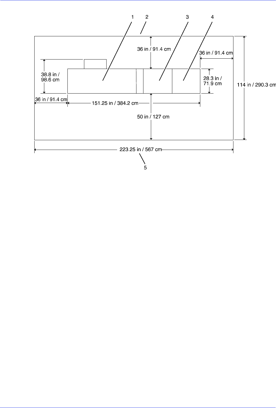
Installation Planning Guide 6-7
Printer requirements and specifications
Figure 6-3 Printer with inverter feeder/stacker and
one feeder/stacker (top view)
1. Printer
2. Back of printer area
3. Inverter feeder/stacker
4. Feeder/stacker
5. Front of printer area
Printer with
inverter feeder/
stacker and
two feeder/stackers
The dimensions of the printer with the inverter feeder/stacker, and
two feeder/stackers are as follows:
• Width: 183.50 inches / 466.1 cm
• Depth: 38.8 inches / 98.6 cm
• Height: 59.6 inches / 151.3 cm
• Weight: 3,109 pounds / 1,411.9 kg
• Total space requirement: 114 by 256.50 inches / 290.3 by
648.9 cm
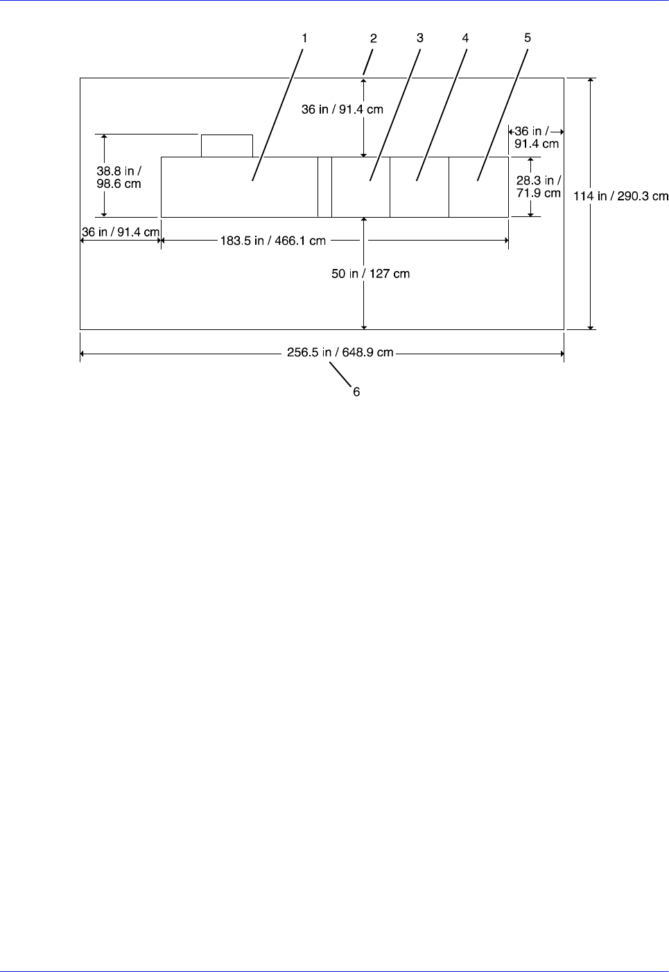
6-8 Installation Planning Guide
Printer requirements and specifications
Figure 6-4 Printer with inverter feeder/stacker and two feeder/
stackers (top view)
1. Printer
2. Back of printer area
3. Inverter feeder/stacker
4. Feeder/stacker
5. Feeder/stacker
6. Front of printer area
Printer with
inverter feeder/
stacker and
three feeder/
stackers
The dimensions of the printer with the inverter feeder/stacker and
three feeder/stackers are as follows:
• Width: 215.75 inches / 548 cm
• Depth: 38.8 inches / 98.6 cm
• Height: 59.6 inches / 151.3 cm
• Weight: 3,630 pounds / 1,648.9 kg
• Total space requirement: 114 by 287.75 inches / 290.3 by
730.8 mm
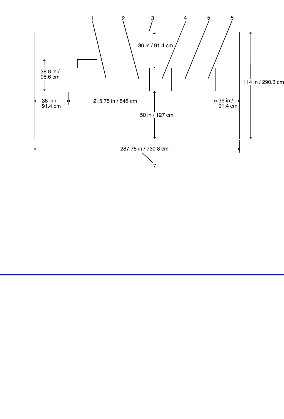
Installation Planning Guide 6-9
Printer requirements and specifications
Figure 6-5 Printer with inverter feeder/stacker and three feeder/
stackers (top view)
1. Back of printer area
2. Printer
3. Inverter feeder/stacker
4. Feeder/stacker
5. Feeder/stacker
6. Feeder/stacker
7. Front of printer area
Bypass transport specifications
The bypass transport option enables you to add a third-party
finishing device. The bypass transport is installed by your service
representative and remains permanently in place. You should not
attempt to remove or reinstall it. The following is
supported by the bypass transport:
•Paper size and weight: You can use all of the paper sizes
and weights supported by the printer in the bypass transport.
•Sheet exit orientation: 1 to N (the same order in which
sheets are fed from the printer), delivered face down.
•Maximum throughput speed: The bypass transport for the
printer supports throughput speeds of up to 180 ppm (pages
per minute). This rate is based on stocks up to 9 by 14.33 /
229 by 364 mm in length.
•Sheet exit height: 34 inches / 86 cm above the floor.
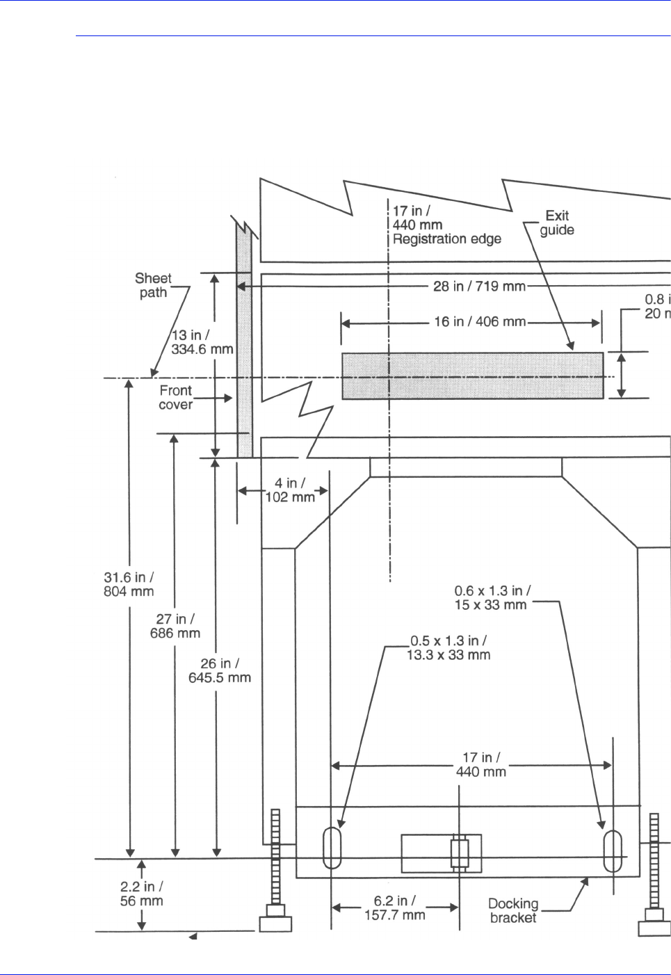
6-10 Installation Planning Guide
Printer requirements and specifications
Bypass transport dimensions
The following pages contain diagrams showing dimensions,
service access, and the paper path for the bypass transport.
Dimensions The following figure shows the dimensions of the bypass transport
in millimeters and inches from the right end view.
Figure 6-6 Bypass transport dimensions
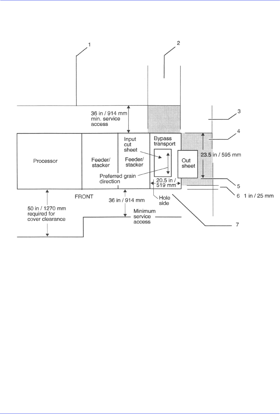
Installation Planning Guide 6-11
Printer requirements and specifications
Service access The following figure provides space planning information and
service access requirements for the bypass transport.
Figure 6-7 Bypass transport space planning diagram (top view)
1. Recommended third-party feeder hardware attaches at rear
of printer
2. Expected third-party input paper feed path
3. Neutral area, to remain unoccupied
4. Shaded areas at rear and right side of the bypass transport
require third-party input/output devices to be undockable
from the feeder/stacker or the bypass transport
5. Register edge of the output sheet
6. Third-party hardware must not extend more than 1 inch /
25 mm beyond bypass transport front cover line for correct
front door access
7. Bypass transport / input enablement jam clearance space is
required
Bypass transport
paper path The following figure shows the paper path through the bypass
transport from a front view.
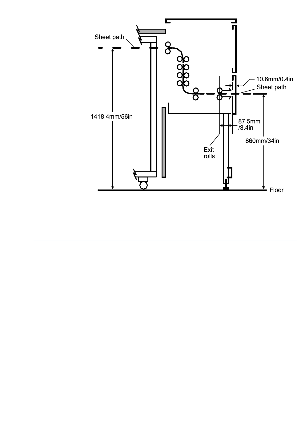
6-12 Installation Planning Guide
Printer requirements and specifications
Figure 6-8 Bypass transport paper path
Configuration diagrams with bypass transport
The following diagrams show the dimensions and space
requirements of the printer with a bypass transport. These
diagrams represent top views of the components, surrounded by
the minimum access space requirements on all sides.
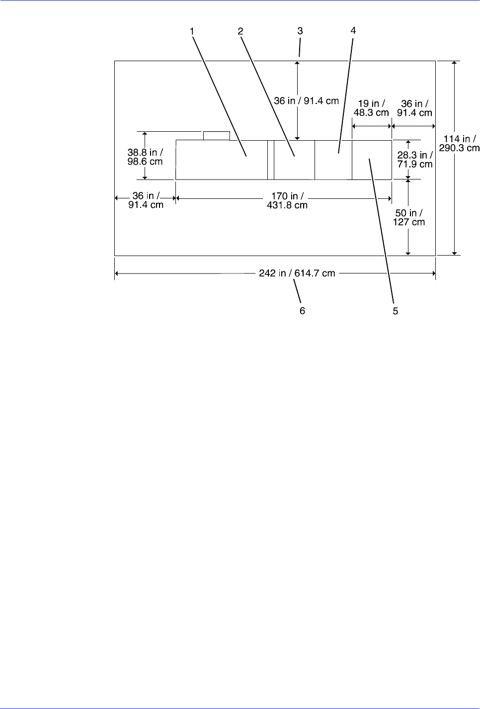
Installation Planning Guide 6-13
Printer requirements and specifications
Figure 6-9 Printer—inverter feeder/stacker and
one feeder/stacker with bypass transport
1. Printer
2. Inverter feeder/stacker
3. Back of printer area
4. Feeder/stacker
5. Bypass transport
6. Front of printer area
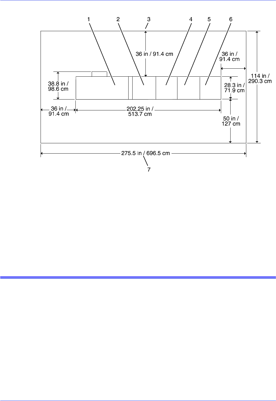
6-14 Installation Planning Guide
Printer requirements and specifications
Figure 6-10 Printer—inverter feeder/stacker and
two feeder/stackers with bypass transport
1. Printer
2. Inverter feeder/stacker
3. Back of printer area
4. Feeder/stacker
5. Feeder/stacker
6. Bypass transport
7. Front of printer area
Space planning guidelines
When determining your space requirements and planning for
shared space between your printers, it is important to consider all
of the components you plan to install.
To ensure all of the space requirements are met, it is important to
work with your Xerox representative.
Before installation, you must consider the following:
• Clearance space requirements where you intend to install the
printer
• Recommended cable lengths and locations (refer to the
“System connections” chapter of this guide for more
information)
• Delivery access requirements

Installation Planning Guide 6-15
Printer requirements and specifications
• Floor leveling
Clearance space requirements
The printer must be installed in a fixed location that provides the
following clearance space:
• 36 inches / 91.4 cm on all sides of each component
• 78 inches / 198 cm of vertical clearance throughout the entire
area
• 24 inches / 61 cm of exclusive operator area in front of each
component
NOTE: There must be a total of 50 inches / 126.9 cm of clearance
space in front of the printer.
Shared space between components
It is best to provide the full amount of clearance space around the
hardware components. Your environment may require you to use
shared space between components such as between the printer
and the controller or between the printer and another Xerox
printing system. You can share the 36-inch / 91.4 cm clearance
space around each component, as long as you follow these rules:
• Space may be shared only with other Xerox equipment.
• Components may share the 36-inch / 91.4 cm general service
clearance areas, but they may not share the 24-inch / 61 cm
operator area in front of each component.
• There must be 78 inches / 198 cm of vertical clearance
throughout the entire area.
NOTE: Finishers that are attached to your bypass transport may
occupy shared space with Xerox equipment. However, they must
be removable to allow servicing of the printer feeders and
stackers. Consult with your Xerox representative to ensure all the
requirements are met.
Shared space configuration diagrams
The following figures illustrate three possible configurations of
shared space.
Back-to-back
shared space The figure below illustrates the two printers placed in a back-to-
back position. This allows the printers to share the entire 36
inches /
91.4 cm of general service space.
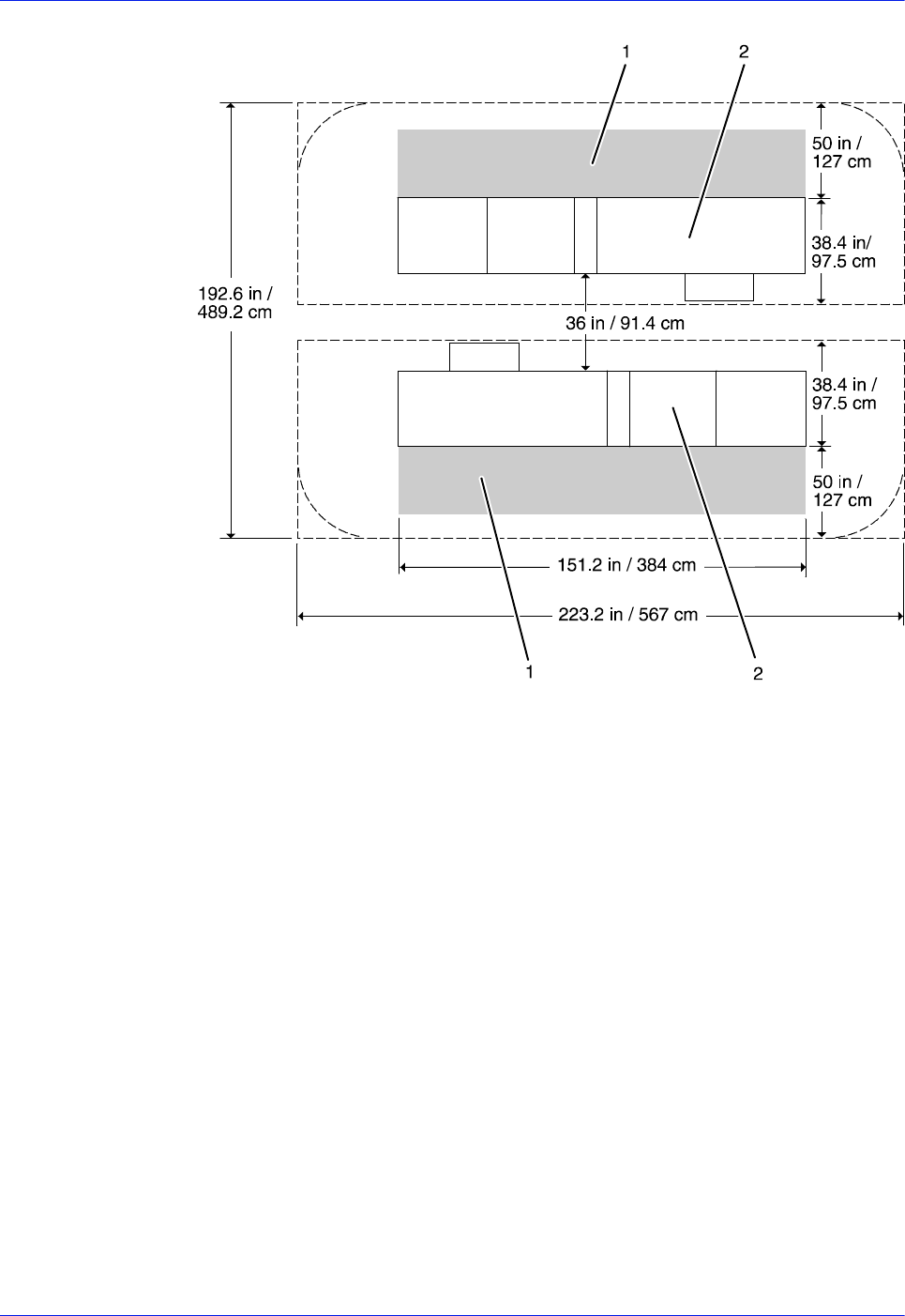
6-16 Installation Planning Guide
Printer requirements and specifications
Figure 6-11 Back-to-back shared service area space
1. Operator area
2. Printer
Face-to-face
shared space The following figure shows the two printers facing each other. The
printers share 26 inches / 30.5 cm of the general service space,
but not the exclusive operator area in front of each printer.
Therefore, the printers should be separated by 24 inches / 61 cm,
plus 24 inches / 61 cm, plus 26 inches / 30.5 cm. This allows for
the entire operator space for each printer, plus the shared general
service area of 26 inches / 30.5 cm.
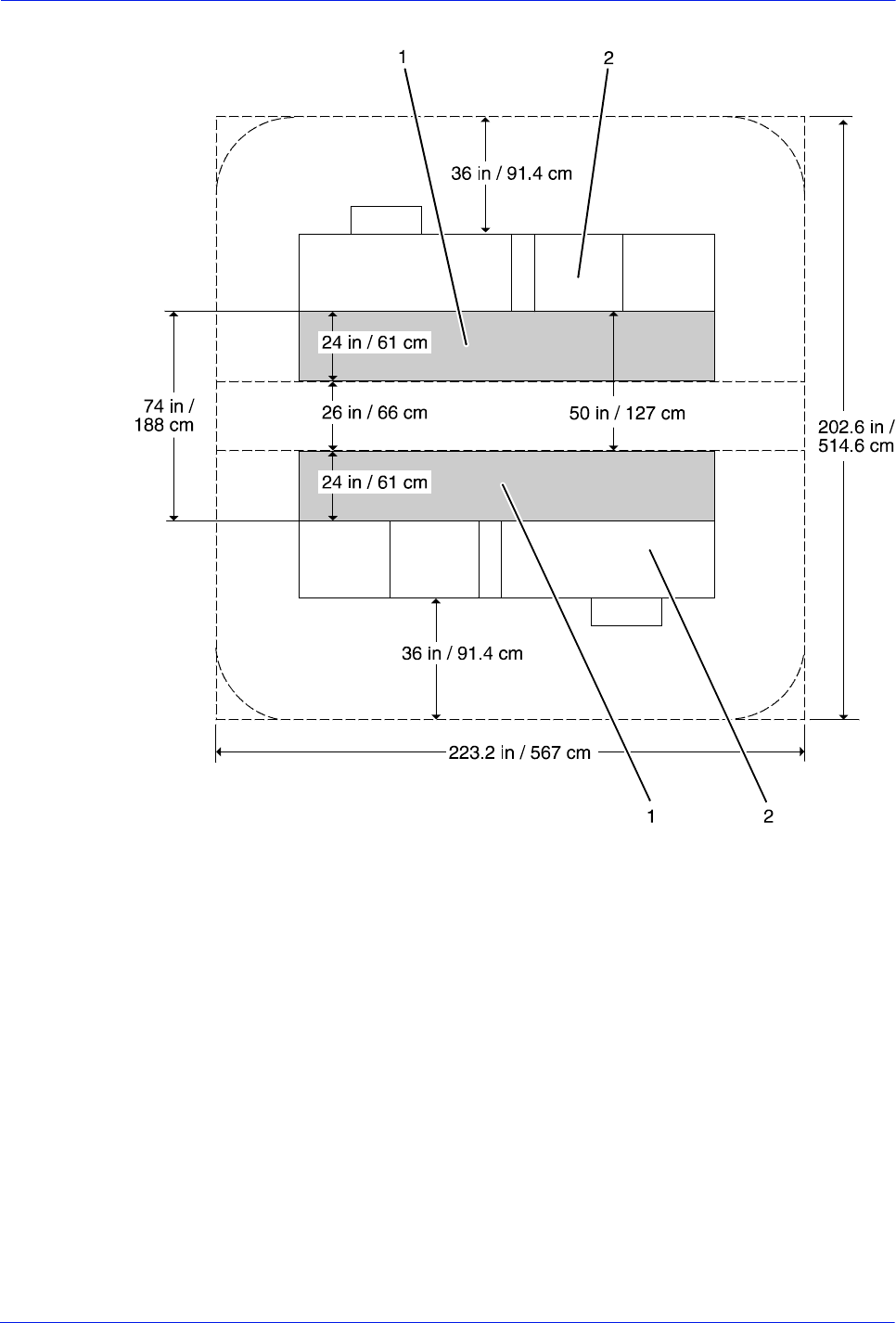
Installation Planning Guide 6-17
Printer requirements and specifications
Figure 6-12 Face-to-face shared service area space
1. Operator area
2. Printer
Face-to-face
shared space The following figure shows the two printers arranged with one
facing the back of the other. Between them is 60 inches / 152.4 cm
of space. This allows for 24 inches / 61 cm of operator space in
front of the printer facing toward the other, plus 36 inches / 91.4
cm of service space behind the printer facing away from the other.
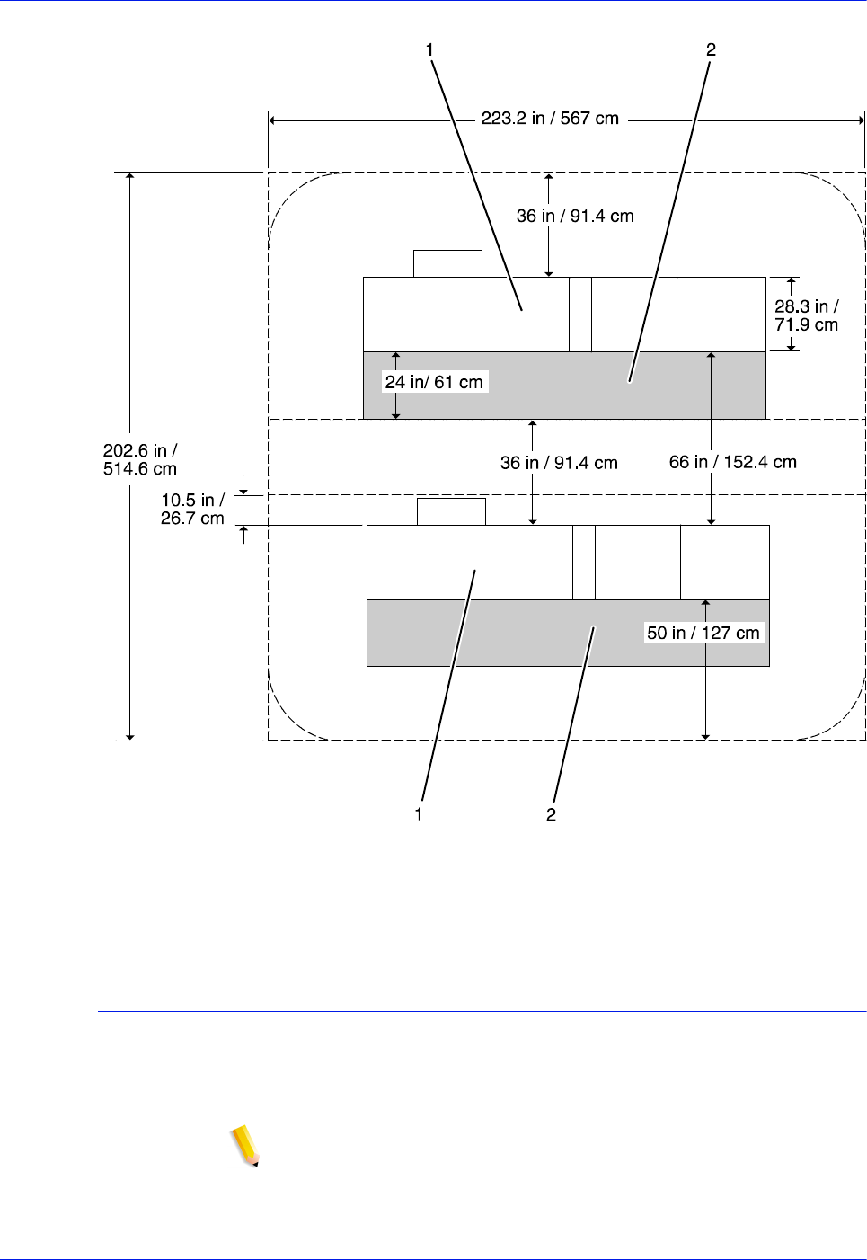
6-18 Installation Planning Guide
Printer requirements and specifications
Figure 6-13 Face-to-back shared space
1. Operator area
2. Printer
Floor leveling
For proper operation, the printer must be perfectly level. On floors
less than two degrees out of level, installation personnel use a
leveling kit to level the machine.
NOTE: The printer will not function properly on floors more than
two degrees out of level.
If the floor is more than two degrees out of level, find another
location for the printer.

Installation Planning Guide 6-19
Printer requirements and specifications
For your reference, two degrees represents a height discrepancy
of approximately 3.8 inches / 9.6 cm measured at the casters with
the printer tilting from left to right, or approximately 0.7 inches / 1.8
cm with the printer tilting from back to front.
If you move the printer after its initial installation, it is your
responsibility to make sure that the printer can be leveled properly.
If you do not have the leveling kit (the printer in its initial location
did not require it), and you need one to level the printer in a new
location, contact your Xerox site representative to
obtain one.
Delivery access requirements
It is easy to overlook the path required to move the equipment
from the truck to the operation site. To determine access, ask the
following questions:
• Does the equipment need to go up or down a stairwell? How
wide is the stairwell?
• Do you have an elevator, if the equipment is to be located
above or below the first floor?
• Is the elevator large enough for the equipment?
• How wide are the hallways and doorways?
• Do you have a loading dock or a specific door to which the
equipment should be delivered?
You need to review these issues before or during the site
inspection conducted by your service representative.
The equipment dimensions are specified earlier in this chapter, so
it is easy to determine whether your hallways and doorways are
wide enough to permit access.
Turning radius
You must also consider the width of the passageway when the
equipment must negotiate a corner, whether into a room, an
elevator, or another passageway.
There are L-shaped turns and T-shaped turns. The diagrams and
the tables that follow show the minimum space required to
maneuver through the turns.
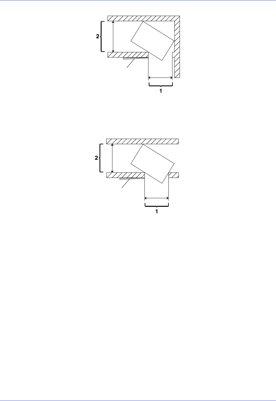
6-20 Installation Planning Guide
Printer requirements and specifications
Figure 6-14 L-shaped turn
Passage 1
Passage 2
Figure 6-15 T-shaped turn
Passage 1
Passage 2
Using the turning
radius tables To use the tables:
1. Measure the minimum width of the passage or doorway you
need to use. This is Passage 1.
2. Find that number (or the next higher number) in the turning
radius table and read across to the corresponding minimum
value for Passage 2, depending on the type of turn the
equipment must negotiate.
Turning radius for
printer with
separated
components
The printing system is delivered with the printer, inverter feeder/
stacker, and each feeder/stacker as separate modules. If
necessary, the printer can be separated into two pieces for ease in
moving. The larger of the two parts contains the xerographic
system; the smaller of the parts (the paper handling module, or
PHM) contains paper trays 1 and 2. Do not confuse these two
parts of the printer with the inverter and feeder/stacker modules,
which have their own turning requirements.
The following table lists the turning requirements for the printer
without the PHM (separated)

Installation Planning Guide 6-21
Printer requirements and specifications
Table 6-6 Turning radius for printer
The following table lists the turning requirements for the printer if it
is upended for easier moving or stair-climbing. This table reflects
requirements for the printer separated from the PHM
Table 6-7 Turning radius for printer (separated and upended on
dolly)
Turning radius for
unseparated
printer components
The following table lists the turning requirements for the printer
when attached to the paper handling module (not separated).
Passage or doorway 1 width Minimum passage 2 width
29 inches / 73.7 cm 74.5 inches / 189.2 cm
30 inches / 76.2 cm 64.5 inches / 163.8 cm
31 inches / 78.7 cm 62 inches / 157.5 cm
32 inches / 81.3 cm 59.5 inches / 151.1 cm
34 inches / 86.4 cm 56 inches / 142.2 cm
36 inches / 91.4 cm 53 inches / 134.6 cm
38 inches / 96.5 cm 50 inches / 127 cm
40 inches / 101.6 cm 48 inches / 121.9 cm
42 inches / 106.7 cm 45.5 inches / 115.6 cm
Passage or doorway 1 width Minimum passage 2 width
30 inches / 76.2 cm 49 inches / 124.5 cm
31 inches / 78.7 cm 43 inches / 109.2 cm
32 inches / 81.3 cm 41 inches / 104.1 cm
34 inches / 86.4 cm 37.5 inches / 95.3 cm
36 inches / 91.4 cm 35 inches / 88.9 cm
38 inches / 96.5 cm 33.5 inches / 85.1 cm
40 inches / 101.6 cm 32 inches / 81.3 cm
42 inches / 106.7 cm 31 inches / 78.7 cm

6-22 Installation Planning Guide
Printer requirements and specifications
Table 6-8 Turning radius for printer (not separated)
Turning radii for
feeder/stacker
modules
The following table lists the turning requirements for the inverter
feeder/stacker module.
Table 6-9 Turning radius for inverter feeder/stacker module
NOTE: These figures are based on inverter/feeder/stacker
dimensions of 28 inches / 711 mm by 42 inches / 1,067 mm.
Passage or doorway 1 width Minimum passage 2 width
29 inches / 73.7 cm 83 inches / 210.8 cm
30 inches / 76.2 cm 76 inches / 193 cm
31 inches / 78.7 cm 73 inches / 185.4 cm
32 inches / 81.3 cm 70.5 inches / 179.1 cm
34 inches / 86.4 cm 66.5 inches / 169 cm
36 inches / 91.4 cm 63.5 inches / 161.3 cm
38 inches / 96.5 cm 61.5 inches / 156.2 cm
40 inches / 101.6 cm 58 inches / 147.3 cm
42 inches / 106.7 cm 55 inches / 139.7 cm
Passage or doorway 1 width Minimum passage 2 width
29 inches / 73.7 cm 43 inches / 109.2 cm
30 inches / 76.2 cm 41 inches / 104.1 cm
31 inches / 78.7 cm 40 inches / 101.6 cm
32 inches / 81.3 cm 38 inches / 96.5 cm
33 inches / 83.8 cm 37 inches / 94 cm
34 inches / 86.4 cm 36 inches / 91.4 cm
35 inches / 88.9 cm 35 inches / 88.9 cm
36 inches / 91.4 cm 34 inches / 86.4 cm
37 inches / 94 cm 33 inches / 83.8 cm
38 inches / 96.5 cm 32 inches / 81.3 cm
39 inches / 99.1 cm 31 inches / 78.7 cm
40 inches / 101.6 cm 31 inches / 78.7 cm
41 inches / 104.1 cm 30 inches / 76.2 cm
42 inches / 106.7 cm 29 inches / 73.7 cm
43 inches / 109.2 cm 29 inches / 73.7 cm

Installation Planning Guide 6-23
Printer requirements and specifications
The following table lists the turning requirements for the feeder/
stacker module.
Table 6-10 Turning radius for feeder/stacker module
NOTE: These turning figures are based on inverter/feeder/stacker
dimensions of 28 inches / 71.1 cm by 32.25 inches / 81.9 cm.
Printer hardware specifications and requirements summary
The following table summarizes the specifications and electrical
requirements of your printer hardware components.
Passage or doorway 1 width Minimum passage 2 width
29 inches / 73.7 cm 33 inches / 83.8 cm
30 inches / 76.2 cm 32 inches / 81.3 cm
31 inches / 78.7 cm 31 inches / 78.7 cm
32 inches / 81.3 cm 30 inches / 76.2 cm
33 inches / 83.8 cm 29 inches / 73.7 cm

6-24 Installation Planning Guide
Printer requirements and specifications
Table 6-11 Printer specifications and power requirements
Device Dimensions (width,
depth, height) Total Weight Heat dissipation Power
requirements
Printer with
inverter feeder/
stacker and one
feeder/stacker
W=151.2 in / 384 cm
H=59.6 in / 151.3 cm
D=38.8 in / 98.6 cm
Total space required
(+ access):
223.25 in W by 114 in D
/ 567 cm W by 290.3 cm
D
2,588 lbs/
1,174.9 kg. DP 100, 115, and
135:
Operating:
28,140 BTU per hr
Standby:
4,454 BTU per hr
Energy Saver:
2,700 BTU per hr
DP 155 and 180:
Operating:
32,770 BTU per hr
Standby:
4,454 BTU per hr
Energy Saver:
2,700 BTU per hr
60 Hz:
DP 100, 115,
and 135:
120/240 VAC
or
120/208 VAC;
50 amp
service;
NEMA L14-
50R;
KVA 7.3
(operating)
DP 155 and
180:
120/208 VAC
(182 V to 220
V),
KVA 7.3
(operating)
Cord 1: 50
amp,
NEMA 14-50R
Cord 2: 30
amp,
NEMA 14-30R
50 Hz:
Consult your
local service
representative.

Installation Planning Guide 6-25
Printer requirements and specifications
Printer with
inverter feeder/
stacker and two
feeder/stackers
W=183.5 in / 466.1 cm
H=59.6. in / 151.3 cm
D=38.8 in / 98.6 cm
Total space required
(+ access):
256.5 in W by 114 in D /
648.9 cm W by 290.3
cm D
3,109 lbs /
1,411.9 kg DP 135:
Operating:
28,140 BTU per hr
Standby:
4,454 BTU per hr
Energy Saver:
2,700 BTU per hr
DP 155 and 180:
Operating:
32,770 BTU per hr
Standby:
4,454 BTU per hr
Energy Saver:
2,700 BTU per hr
60 Hz:
DP 135:
120/240 VAC
or
120/208 VAC;
50 amp
service;
NEMA 14-50R,
KVA
8.1(operating)
DP 155 and
180:
120/208 VAC
(182 V to 220
V),
KVA
8.1(operating)
Cord 1: 50
amp,
NEMA 14-50R
Cord 2: 30
amp,
NEMA 14-30R
50 Hz:
Consult your
local service
representative
Device Dimensions (width,
depth, height) Total Weight Heat dissipation Power
requirements

6-26 Installation Planning Guide
Printer requirements and specifications
Space planning templates
The dimensions and space requirements for your printer
components are provided earlier in this chapter. The space
planning templates are designed to simplify the space planning
process by helping you to create a floor plan for your base
components, particularly if you have shared clearance space.
The easiest way to use the space planning templates is to move
the templates around on the grid located at the end of this section
and determine the optimum placement for your printer
components. Make sure to consider other pieces of equipment,
Printer with
inverter feeder/
stacker and
three feeder/
stackers
W=216 in / 730.8 cm
H=59.6 in / 151.3 cm
D=38.8 in / 98.6 cm
Total space required
(+ access):
288 in W by 114 in D /
730.8 cm W by 290.3
cm D
3,630 lbs /
1,648.9 kg DP 135:
Operating:
28,140 BTU per hr
Standby:
4,454 BTU per hr
Energy Saver:
2,700 BTU per hr
DP 155 and 180:
Operating:
32,770 BTU per hr
Standby:
4,454 BTU per hr
Energy Saver:
2,700 BTU per hr
60 Hz:
DP 135:
120/240 VAC
or
120/208 VAC;
50 amp
service;
NEMA 14-50R,
KVA
8.1(operating)
DP 155 and
180:
120/208 VAC
(182 V to 220
V),
KVA
8.1(operating)
Cord 1: 50
amp,
NEMA 14-50R
Cord 2: 30
amp,
NEMA 14-30R
50 Hz:
Consult your
local service
representative
Bypass
transport W=20.4 in / 51.9 cm
H=56.1 in / 142.5 cm
D=28.3 in / 71.9 cm
176 lbs /
80 kg --- ---
Device Dimensions (width,
depth, height) Total Weight Heat dissipation Power
requirements

Installation Planning Guide 6-27
Printer requirements and specifications
such as cabinets, tables, and optional equipment when planning
your space. Your customer support representative can help you
plan space for additional components.
The templates are to scale with the grid; each square is equal to
12 by 12 inches / 30.5 by 30.5 cm. The curved dotted lines in the
corners of the space perimeters indicate the corners that may be
rounded off while still maintaining the required clearance space.
There are a number of factors to keep in mind when planning your
site, including the following:
• Clearance space requirements
• Cable length
Refer to these sections in this manual when considering the
various factors involved in planning the appropriate location for
your printing system.
When determining your space requirements, remember to
consider all of the components you plan to have installed. If you
have a bypass transport or input enablement device option on
your printing system, you should contact the sales representatives
for the company from which you purchased your finishers and
feeders, as well as your Xerox representative, to ensure that all of
your space requirements are met.

6-28 Installation Planning Guide
Printer requirements and specifications
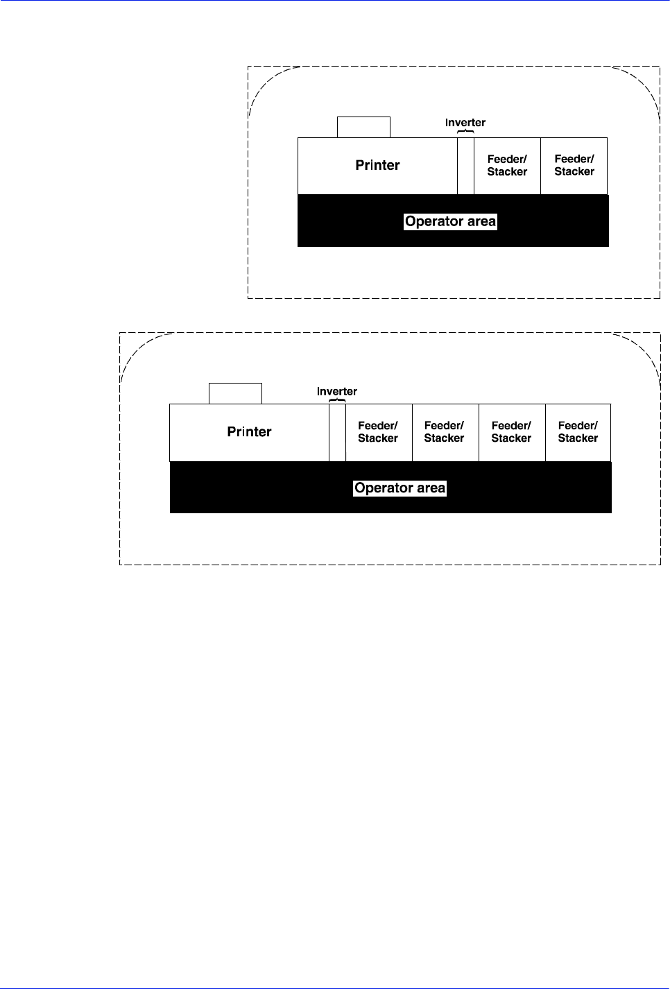
Installation Planning Guide 6-29
Printer requirements and specifications

6-30 Installation Planning Guide
Printer requirements and specifications
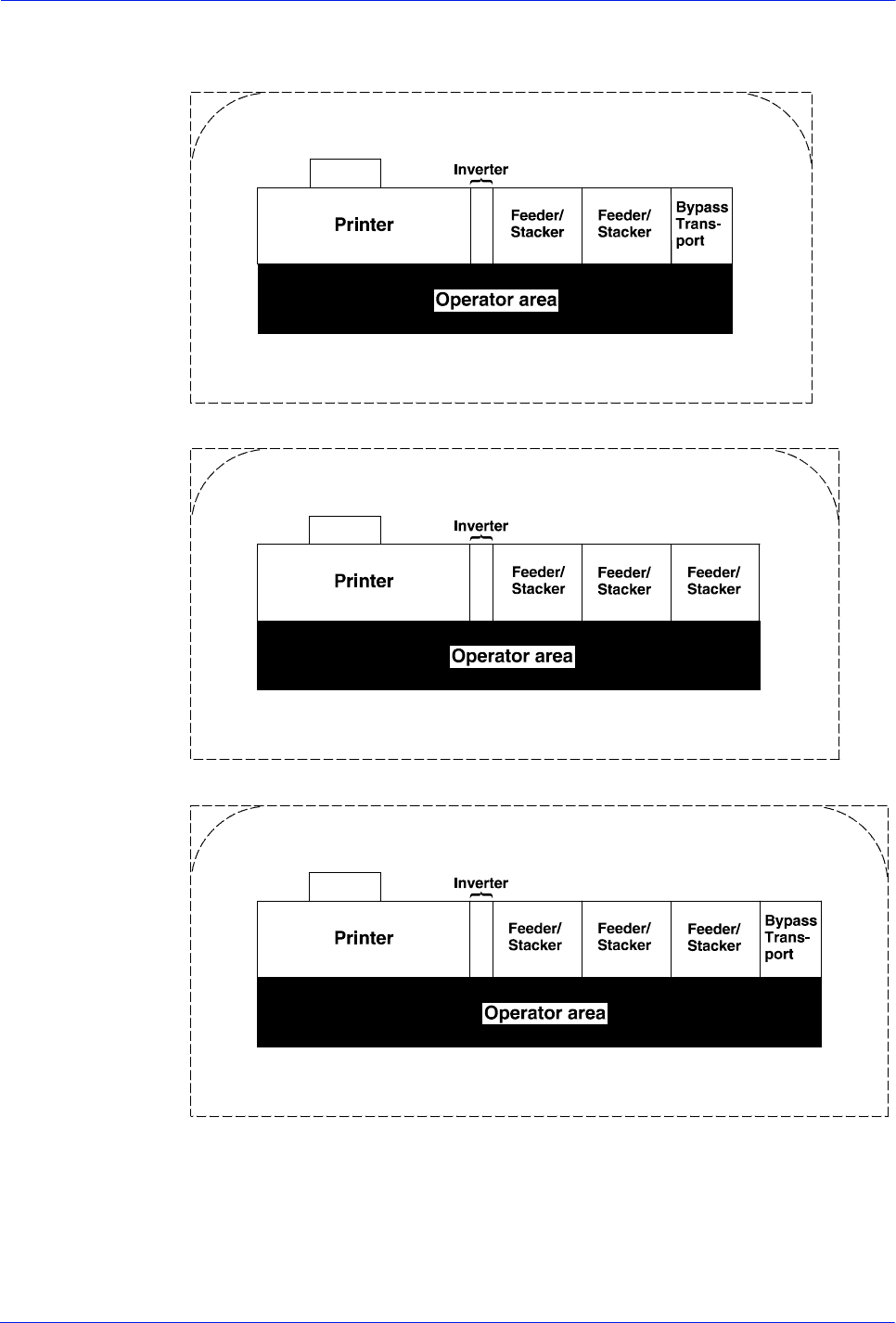
Installation Planning Guide 6-31
Printer requirements and specifications

6-32 Installation Planning Guide
Printer requirements and specifications
Installation Planning Guide 6-33
Printer requirements and specifications
1
1
2
3
4
5
6
7
8
9
10
11
12
13
14
15
16
17
18
19
20
21
22
23
24
25
26
27
28
29
30
31
32
33
34
35
36
37
38
39
40
234567891011121314
15 16 17 18 19 20 21 22 23 24 25 26 27 28
C
O
D
o
e
d
L
n
e
GRID PATTERN
1/4 inch represents one foot
u
t
n
t
t
i

6-34 Installation Planning Guide
Printer requirements and specifications
Installation Planning Guide 7-1
7 System connections
This chapter provides cable requirements for your Xerox
DocuPrint 100/115/135/155/180 EPS. It also provides information
about channel-attaching your printer. To ensure all of your cable
requirements are met, work with your Xerox representative.
Cable lengths
Cable lengths are important considerations in planning your
layout, as components can be separated only up to the length of
the data interface cables that connect them.
Cables supplied with the printer are long enough to meet the
needs of most installations. Some of these cables are specific
lengths to conform to engineering and safety standards.
Interface cable The printer and controller can be separated up to the length of the
interface cables that connect them. The printer and controller are
connected by a 20 foot / 6.1 meter cable, or an optional 50 foot /
15.2 meter cable.
Power cables The printing system power cable lengths are as follows:
Table 7-1 Power cable lengths
WARNING: Using an inappropriate alternate cable may degrade
the performance of your equipment and may also be hazardous.
NOTE: Cable length loss must be factored in if equipment is
installed in a raised-floor environment. You should also consider
that part of the length of a cable is routed inside the equipment to
connect with interior power or data receptacles.
Cable locations
To run the cables beneath the flooring, you must know where the
cables enter and exit the printer. The following diagrams shows
that location marked with an X.
Power cable Length
Controller 8 feet / 2.4 m
Printer 15 feet / 4.5 m
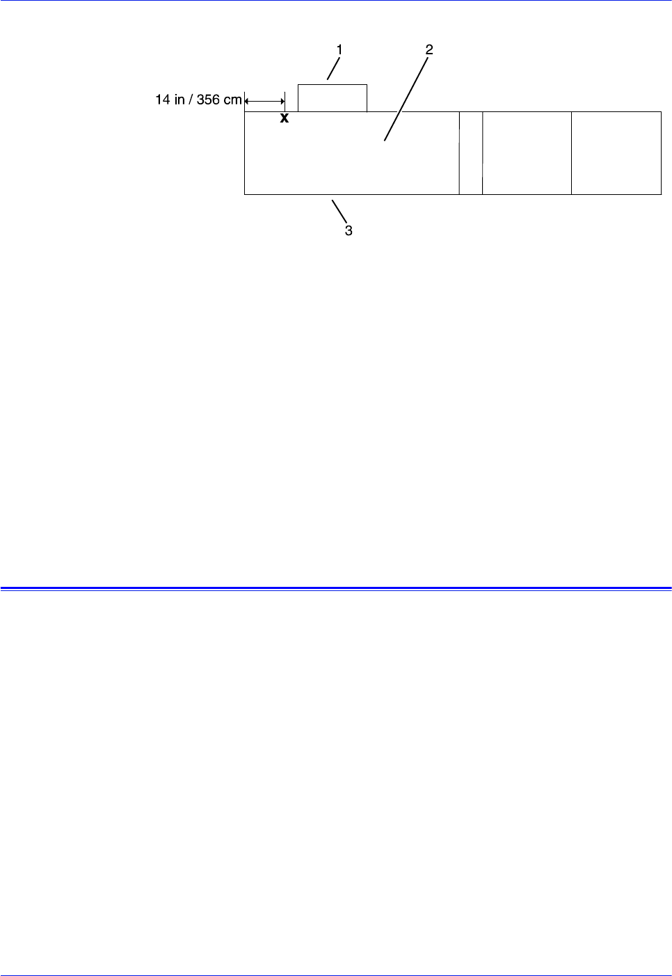
7-2 Installation Planning Guide
System connections
Figure 7-1 Cable enter/exit location (top view)
1. Back of printer area
2. Printer with feeder/stacker modules
3. Front of printer area
All power cords attach to the back of the printer. Power cord
distances from the left end of the printer (as you face it) are:
•DP 100, 115, and 135–distance from end of printer:
• 14 inches / 356 mm
•DP 155 and 180–distance from end of printer:
–Cord 1: 36 inches / 914 mm (with ELCI)
–Cord 2: 23 inches / 584 mm (with ELCI)
Channel attachments
The Xerox DocuPrint 100/115/135/155/180 EPS conforms to IBM
standards and requirements for any channel-attached printer.
When you channel-attach your printing system, keep the following
in mind:
• Channel length is usually determined by the length of the
cables, the number of devices on the channel, and the number
of connections in the cable itself (for example, connecting two
cables to each other).
• Subtract 15 feet / 3.8 m from the total allowable cable length
for any device attached to the channel or for any connection of
two cables.
• IBM channel cable lengths are as follows:
– Gray: 200 feet / 61 m (with one device, 185 feet / 56 m)
– Blue: 400 feet / 122 m (with one device, 385 feet / 117 m)

Installation Planning Guide 7-3
System connections
For further information, refer to the following IBM manuals:
• IBM System 360 and System 370 Input-output Interface
Channel to Control Unit OEM Information (#GA22-6974-3825)
• Page Printer Product Description (#G544-3482)
• 3825 Introduction and Planning Guide (#G544-3480)

7-4 Installation Planning Guide
System connections

Installation Planning Guide 8-1
8 Installation
This chapter describes the activities performed by you and Xerox
personnel during the installation of the Xerox DocuPrint 100/115/
135/155/180 EPS hardware and software components. Before
installation can begin, you must complete the tasks described in
the “Preparing for installation” chapter of this guide.
Installation process
Xerox personnel are responsible for the physical installation of the
printing system hardware components and the software.
NOTE: For customers outside the United States, contact your
local Xerox operating company for your specific installation
process.
The installation process can take one or several days to complete.
Equipment, software kits, and documentation kits may arrive in
one day, or over the course of several days. When all of the
necessary items are in place, Xerox personnel will complete the
installation of the printer components.
In the United States, the steps in the installation process typically
occur in the following order:
1. Xerox personnel install all printer hardware and connects the
controller to your site’s network through the Ethernet
connector you supply. This process takes approximately four
hours if all the necessary network and electrical connectors
are in place.
2. Xerox personnel load software on the controller
(approximately 1.5 hours).
3. Xerox personnel download Xerox client software, if applicable,
on one client workstation to validate the installation (15
minutes). Software is downloaded on another client
workstation as part of training conducted by your systems
analyst. All other client software installations are your
responsibility.
4. Xerox personnel test the system and run sample jobs (30
minutes).
5. Xerox personnel conduct initial operations training (four to six
hours).
6. Xerox personnel review preventive maintenance schedules
and service call procedures.

8-2 Installation Planning Guide
Installation
Your responsibilities
Xerox personnel are responsible for the physical installation of the
printer components and for loading the software and applications.
You have the general site responsibility of ensuring that the right
personnel, supplies, and network information are available.
At the time of installation, you should do the following:
• Make sure that your system administrator is available during
the loading of software.
• For software loading purposes, be prepared to provide Xerox
personnel with network information from the preinstallation
worksheets. Refer to the Getting Ready for Installation manual
for specifics regarding network information.
• Designate two client workstations for downloading Xerox client
software if applicable: one for initial system validation and
another for use in operator training provided by your systems
analyst.
• If your system will be connected to an IBM host through a
channel, provide the host channel address, channel unit
address, and data transfer mode.
• If your system will be connected to an IBM host through
Socket TCP/IP, provide the host IP address and port number.
• Check the documentation and software kits with their packing
lists for completeness.
• Load Xerox client software on any additional client
workstations.
Remember that you are responsible for supplying, installing,
and maintaining your client workstations and the Ethernet local
area network (LAN) that connects them with the printing
system.
• Have test jobs ready to run.
• Have your operators available for training.
Refer to the installation planning checklist in the “Preparing for
installation” chapter of this guide for a complete list of
responsibilities.
Defining the printer to the host
Prior to installation of the printing system, your host system must
be configured to communicate with the Xerox DocuPrint 100/115/
135/155/180 EPS. This requires defining several parameters to
your host. The required information and configuration procedures
differ according to your connectivity type (channel or TCP/IP), and

Installation Planning Guide 8-3
Installation
your host environment. You will need to provide these parameters
to your Xerox representative on installation day.
Software licensing
When you purchase a Xerox DocuPrint 100/115/135/155/180
EPS, you receive a license to use the operating system software.
This license is enabled by entering a 20-character alphanumeric
string at the controller. Your Xerox or service representative
obtains this license string for you and enters it when your printing
system is installed.
Ongoing maintenance
After the installation of your printing system, there are a few
ongoing tasks that must be performed. These tasks may include
the following:
• Maintaining an adequate inventory of consumable supplies
• Overseeing routine maintenance and meter reporting
• Arranging for additional operator training
• Ordering additional fonts
• Ordering additional documentation
• Placing service calls for hardware problems
• Obtaining assistance in solving software-related problems
As installation coordinator, it is your responsibility to designate the
staff members responsible for these tasks.
Routine maintenance
A number of routine maintenance tasks must be performed to
ensure maximum efficiency of your printer. These tasks include:
• Adding standard dry ink to your printer
• Adding fuser agent
• Replacing the dry ink waste container
• Cleaning sensors in the printer
• Cleaning the exterior surfaces of the system
Step-by-step instructions on performing these routine
maintenance tasks are contained in the Operator Guide. You need
to decide how many operators will be responsible for performing
these maintenance tasks. Most maintenance procedures are

8-4 Installation Planning Guide
Installation
covered in the initial operator training provided shortly after
installation.
Meter reading and reporting
As print jobs are processed, the printing system accumulates,
saves, and maintains usage data.
During the last five working days of each month, you need to
review and transmit the data to Xerox for billing purposes. Refer to
your DocuPrint 100/115/135/155/180 EPS Operator Guide for
complete instructions on how to report meter readings.

Installation Planning Guide A-1
A Supplies
This appendix provides information and specifications for media
used with your Xerox DocuPrint 100/115/135/155/180 EPS
printer. Instructions for ordering supplies are also provided.
Consumable supplies (those that are depleted during operation of
the system), such as paper, dry ink, developer, fuser agent, etc.,
must be ordered for your printer. It is important that an adequate
supply of these items be on hand for installation, and that your
supply be maintained afterwards.
Paper and other throughput stocks
The success of any print run is greatly dependent on the proper
selection, care, and handling of the stock used.
Selecting paper
Select your paper carefully. If you do not use the proper paper,
you increase the probability of paper jams and misfeeds. The
stocks you use must meet the specifications set forth by Xerox for
operability in the printer. For additional information about paper
specifications, refer to Helpful Facts about Paper, delivered with
your printer.
Acceptable paper
stocks and sizes The printer accepts the following standard size cut-sheet papers:
• 7 by 10 inches / 178 by 254 mm (with 7-inch kit option)
• B5: 7.17 by 10.12 inches / 182 by 257 mm (with 7-inch option)
• US Letter: 8.5 by 11 inches / 216 by 279 mm
• US Legal: 8.5 by 14 inches / 216 by 356 mm
• A4: 8.27 by 11.69 inches / 210 by 297 mm
• B4 (European): 9.84 by 13.89 inches / 250 by 353 mm
• JIS B4 (Japanese): 10.12 by 14.33 inches / 257 by 364 mm
• US Ledger/US Tabloid: 11 by 17 inches / 279 by 432 mm
• A3: 11.69 by 16.54 inches / 297 by 420 mm
Recommended
weight and grade Use a good quality, xerographic-grade paper. For best results,
use paper that is 20-pound or 80 gsm (grams per square meter)
bond, xerographic grade. Xerox 4024 Dual Purpose Paper
provides optimal performance in the printer. (Refer to the
consumable supplies table later in this appendix.)

A-2 Installation Planning Guide
Supplies
Use paper within these parameters:
• Lightest: 16-pound (65 gsm) bond
• Heaviest: 110-pound (200 gsm) index
Characteristics The paper stock should have the following characteristics:
• Low moisture content (a paper-to-moisture ratio below 5.7
percent). Paper with higher moisture content may curl and
jam.
• Smooth surface
• Moisture-resistant wrapping
• No defects (bent edges, uneven surfaces)
• Grain long (parallel with the long side of paper)
Paper is usually fed into the printer with the long side as the
leading edge (except 11 by 17-inch or A3 paper). When you
purchase paper, buy long-grain paper. Make sure the grain is
parallel with the long side (long-grain) for the most reliable
feeding and stacking.
Special stocks Following are some guidelines for choosing and using special
materials:
Guidelines for
choosing and using
special materials:
•Labels: Must be the type designed for high-speed printers
and must meet the specifications described in the section
above. Loading instructions are printed on all paper trays.
Use only the processor feeding trays (trays 1 and 2) for labels.
Load labels in the tray with the label side up.
You can direct printed labels to any output tray. Be sure the
printed labels are stacked face up in the output tray, to avoid
ink offsetting and jams due to delamination.
•Transparencies: Must be the type designed for high-speed
printers and must meet the specifications described in the
section above. Loading instructions are printed on all paper
trays.
Load transparencies with the opaque strip to the right. All
printed transparencies are delivered to the sample tray.
As long as they meet your printer’s paper specifications, you
can also use:
•Tinted paper: Available in a variety of colors, it has many
uses, including calling attention to certain printed material,
separating special sections, or dividing chapters of a report.
•Preprinted paper: May be letterhead, forms, or logos.
•Predrilled paper: Has a varying number of holes for use in
binders or binder rings. Before loading predrilled paper, fan it
to remove loose plugs that could cause paper jams. Load
predrilled paper in the printer with holes to the right.
•Perforated paper
•Pre-cut or full tabs

Installation Planning Guide A-3
Supplies
•Carbonless paper
NOTE: The printer can print on precollated or ordered stocks,
including ordered tabs. However, jam recovery is not supported
with these stocks.
Paper sizing and print speed
The printer paper trays have edge guide sensors that detect paper
length and width. The system selects correct paper trays for the
print job based on the paper size specified in the job, as follows:
• If an exact match is found, the print job continues.
• If an exact match is not found, the programmer can specify in
the job for the printer to either:
– Stop printing the job and print an error sheet
– Print the data on an oversized sheet.
If you encounter any problems related to paper sizing, contact
your lead operator, systems specialist, or service representative.
Paper width and throughput speed (LCDS printing only)
The width of the paper you use for your LCDS print job is directly
related to the rate at which the printer can print the job. The rate at
which a job prints is called the “throughput speed” and is
measured in pages per minute (ppm).
NOTE: “Pages per minute” actually means “impressions per
minute,” referring to one side of a printed sheet.
A pitch is the amount time the printer takes to image a page on the
photoreceptor belt. The term “pitch mode” refers to the number of
pitches that can occur during one complete photoreceptor
revolution. The pitch mode in which a specific job prints is based
on the paper size used for that job.
The following tables list the pitch mode boundary values, paper
widths, and related printing speeds for the system. Notice that the
shorter the paper width, the higher the pitch mode and the faster
the throughput speed (higher page per minute rate).
A-4 Installation Planning Guide
Supplies
Table A-1 Throughput data DP100
Table A-2 Throughput data DP115
Table A-3 Throughput data DP135
Table A-4 Throughput data DP155
Table A-5 Throughput data DP180
Pitch Paper width Speed
57 to 12.12 in / 178 to 308 mm 100 ppm
412.12 to 15.31 in / 308 to 389 mm 77 ppm
315.31 to 17 in / 389 to 432 mm 58 ppm
Pitch Paper width Speed
67 to 10.19 in / 178 to 259 mm 116 ppm
510.19 to 12.12 in / 259 to 308 mm 96 ppm
412.12 to 15.31 in / 308 to 389 mm 77 ppm
315.31 to 17 in / 389 to 432 mm 58 ppm
Pitch Paper width Speed
87 to 7.4 in / 178 to 188 mm 154 ppm
77.4 to 9.01 in / 188 to 229 mm 135 ppm
69.01 to 10.19 in / 229 to 259 mm 116 ppm
510.19 to 12.12 in / 259 to 308 mm 96 ppm
412.12 to 15.31 in / 308 to 389 mm 77 ppm
315.31 to 17 in / 389 to 432 mm 58 ppm
Pitch Paper width Speed
67 to 10.19 in / 178 to 259 mm 154 ppm
510.19 to 12.12 in / 259 to 308 mm 128 ppm
412.12 to 15.31 in / 308 to 389 mm 103 ppm
315.31 to 17 in / 389 to 432 mm 77 ppm
Pitch Paper width Speed
87 to 7.4 in / 178 to 188 mm 206 ppm
77.4 to 9.01 in / 188 to 229 mm 180 ppm
69.01 to 10.19 in / 229 to 259 mm 154 ppm
510.19 to 12.12 in / 259 to 308 mm 128 ppm

Installation Planning Guide A-5
Supplies
Each time a job requires a different paper size that changes
across a pitch boundary, the system performs a time-consuming
xerographic quality adjustment. When the printing speed of an
LCDS job appears to degrade due to the use of mixed stock sizes,
you may be able to improve the speed by using the LCDS
OUTPUT command TMODE parameter in the JSL to run the print
job in a lower pitch mode. Refer to the OUTPUT TMODE
parameter in Using LCDS Print Description Language for
information on using this LCDS command.
Similarly, if the system cycles down frequently because your
external finishing equipment has a slower throughput rate than the
printing system, you can use the TMODE parameter of the LCDS
OUTPUT command to lower the pitch mode to match the speed of
the finishing equipment. This can improve overall throughput by
avoiding time-consuming cycle downs.
NOTE: “Pages per minute” actually means “impressions per
minute,” referring to one side of a printed sheet.
Paper size and pitch mode minimum and maximum
The illustrations in this section show the pitch modes in which you
can operate with the smallest and largest size papers supported
by the printing system.
Using small paper
sizes in 8 pitch
mode
Printing in 8 pitch mode provides the highest throughput speed
available —up to 154 ppm for the DP135 printer and up to 206
ppm for the DP180 printer. (The DP100 printer does not support 8-
pitch mode.) However, you should keep the following in mind
when you select the paper you want to use for this mode:
• Paper sizes smaller than 8 inches / 203 mm in width are
supported only when the optional 7 inch Paper Kit is installed
on the printer.
• The leading edge of any paper used in the printer cannot be
less than 10 inches / 254 mm long.
The following figure illustrates the maximum and minimum paper
sizes supported in 8 pitch mode.
412.12 to 15.31 in / 308 to 389 mm 103 ppm
315.31 to 17 in / 389 to 432 mm 77 ppm
Pitch Paper width Speed
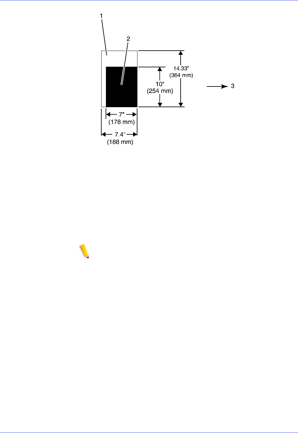
A-6 Installation Planning Guide
Supplies
Figure A-1 8 pitch mode paper sizes
1. Maximum paper size for 8 pitch mode
2. Minimum paper size for 8 pitch mode
3. Travel direction of sheets out of paper tray
Using large paper
sizes in 3 pitch
mode
Large paper sizes with widths of 15.31 to 17 inches / 389 to 432
mm are supported only in 3 pitch mode and must feed short edge
first. These paper sizes slow down the throughput speed.
Therefore, a short edge feed job takes longer to print than a long
edge feed job.
NOTE: The system can support 14 by 17 inch / 356 by 432 mm,
20 pound or 80 gsm paper stock in 3 pitch mode. However,
printing performance is not guaranteed for all types of paper of this
size. Heavy (110 pound / 200 gsm) and light (16 pound / 60 gsm)
weight papers can cause jams throughout the system, and are not
recommended.
The following figure illustrates the maximum and minimum paper
sizes supported in 3 pitch mode.
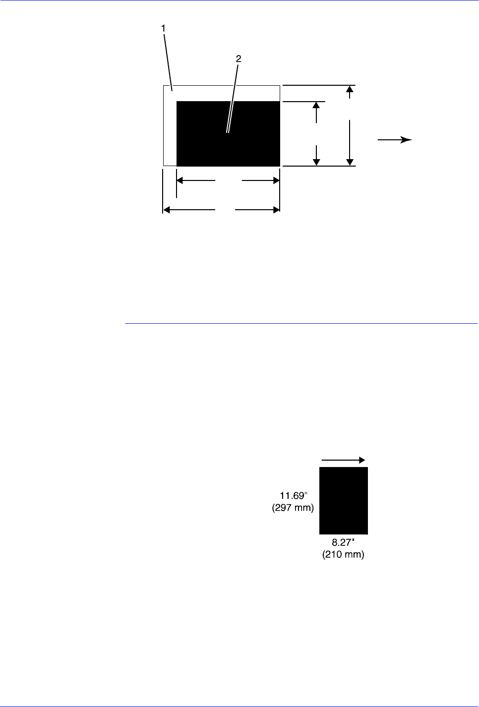
Installation Planning Guide A-7
Supplies
Figure A-2 3 pitch mode paper sizes
1. Maximum paper size for 3 pitch mode
2. Minimum paper size for 3 pitch mode
3. Travel direction of sheets out of paper tray
Feed direction for standard paper sizes
Currently, 14.33 inches / 364 mm is the maximum paper length for
which the system supports long edge feeding (5 to 8 pitch mode).
Any papers with long edges greater than this (such as 11 by 17
inch / 279 by 432 mm paper) must be loaded for short edge
feeding (3 or 4 pitch mode).
European papers The following figures show how European paper sizes feed
through the printer in various pitch modes.
Figure A-3 A4 / 210 by 297 mm paper feeding (long edge feed)
14.33 in
(364 mm)
10 in
(254 mm)
15.31 in
(389 mm)
17 in
(432 mm)
3
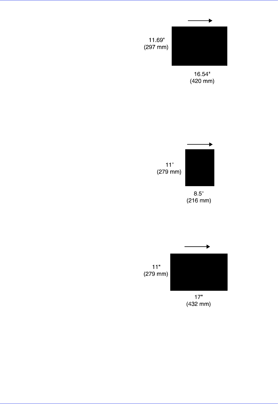
A-8 Installation Planning Guide
Supplies
Figure A-4 A3 / 297 by 420 mm paper feeding (short edge
feed)
US papers The following figures show how some US paper sizes feed
through the printer in the different pitch modes.
Figure A-5 US Letter / 8.5 by 11 inch paper feeding (long edge
feed)
Figure A-6 US Ledger or US Tabloid / 11 by 17 inch paper
feeding (short edge feed)
B4 papers There are two versions of B4 paper: European (ISO B4: 9.84 by
13.89 inches / 250 by 353 mm) and Japanese (JIS B4: 14.33 by
10.12 inches / 364 by 257 mm). European B4 feeds long edge
first, while JIS B4 must feed short edge first because its length is
greater than 14 inches or 356 mm.
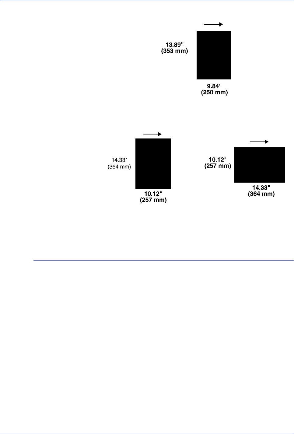
Installation Planning Guide A-9
Supplies
Figure A-7 B4 / 250 by 353 mm paper feeding (long edge feed)
Figure A-8 JIS B4 / 257 by 364 mm paper feeding (may be long
or short edge feed)
Paper care
Once you have purchased your paper, you must be sure it is
stored and conditioned properly, so that it performs optimally in
the printer with a minimum of jams.
Storing paper Paper has a tendency to curl under the heat that is present inside
xerographic equipment. To minimize the amount of curling, use
paper with low moisture content. Paper with excessive moisture
content has a tendency to jam because of the greater curl. The
maximum recommended moisture content is 5.7 percent.
Keep these points in mind when preparing your paper storage
area:
• Store paper in its own wrapper; do not leave it unwrapped or
where it can be damaged by dampness or heat.
• Store paper on a flat surface and not on its side or edge.
• Store reams of paper in a closed cabinet.
• Always store paper in a cool, dry area. Store on pallets or
shelves, not on the floor.
• Plan ahead and keep at least a day’s supply of paper in the
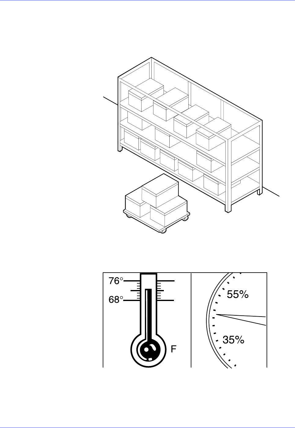
A-10 Installation Planning Guide
Supplies
same area as the printer to allow environmental stabilization
prior to printing.
For more detailed information on paper for Xerox printers, refer to
Helpful Facts about Paper, provided with your printer.
Figure A-9 Storing paper correctly
Figure A-10 Recommended temperature and humidity for
paper storage
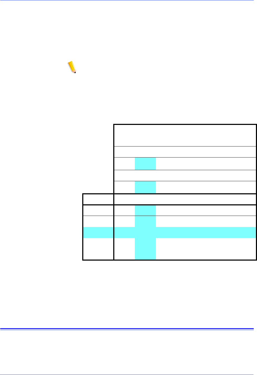
Installation Planning Guide A-11
Supplies
Conditioning paper Because temperature and humidity affect paper performance in
the printer, you need to condition paper before using it. To do this,
store paper for a specified length of time in the same type of
environment as your printer.
The length of time you should condition your paper depends on
the amount of paper and the difference between the storage and
operating temperatures.
NOTE: The numbers in the top two rows indicate the temperature
difference between the storage area and the operating
environment, not actual room temperatures.
Use the following chart to determine the length of time needed to
condition stacked cartons of paper.
Table A-1 Time required for paper conditioning
Example: (See the shaded rows in the table above.) If you want to
move ten cartons of paper from a storage area with a temperature
of 90 oF to an operating area with a temperature of 75 oF (a 15o
difference), you should do so at least 14 hours before using the
paper.
Other supplies
This section describes the supplies other than paper that are
necessary for installation and afterward. Your sales representative
will help you place your initial supply order.
Temperature differences between storage
and
operating areas
Fahrenheit
10o15o20o25o30o40o50o
Centigrade
5.5o8.5o11o13o17o22o28o
Cartons Hours
1 4811 14 17 24 34
5 5912 15 18 25 35
10 814 18 22 27 38 51
20 11 16 23 28 35 48 67
40 14 19 26 32 38 54 75

A-12 Installation Planning Guide
Supplies
Dry ink
Dry ink (also called toner) is the black powder that forms the
image on the printed page. There are three cartridges of dry ink in
each carton. You should keep at least one extra cartridge on hand
at all times. The disposable cartridges are easily changed with no
mess. The consumption rate of Xerox dry ink is approximately one
cartridge per 60,000 pages. Use only dry ink that is specified for
use in the printer, as described in the consumable supplies table.
MICR dry ink MICR dry ink is the magnetic black powder which forms the image
on the printed MICR document. There are three cartridges of
MICR dry ink in each carton. The consumption rate of Xerox MICR
dry ink is approximately one cartridge per 60,000 pages. Use only
MICR dry ink in your MICR printer.
The dry ink that is used with the DP 100/115/135/155/180 MICR
EPS is designed for MICR printing and does not function well
when used in non-MICR systems. The same procedure used for
non-MICR printing systems is used to add the dry ink to the 96/
4635/180 MICR printer.
NOTE: Dry ink (toner) yields are based on 7% area coverage.
Your yield may vary, depending on coverage.
CAUTION: Use only MICR dry ink in the DP 100/115/135/155/
180 MICR EPS printers. Do not use standard dry ink. MICR dry
ink cannot be reused.
Fuser agent
Fuser agent (the lubricant for the printer fuser) is a consumable
item required by the printer. The consumption rate of Xerox fuser
agent is approximately one bottle per 250,000 pages. For product
information, refer to the consumable supplies table in this
appendix.
US only: You should keep at least two boxes (each box contains
one bottle) on hand for installation by the service representative.
Developer
Developer is not consumed by the printer but does have an
effective life of approximately 1,000,000 pages per carton
(600,000 per carton for MICR developer). Both kinds of developer
are guaranteed by Xerox for 600,000 pages per carton. Developer
is a required item and must be kept on hand.
Use only the developer specified for use in your printer.

Installation Planning Guide A-13
Supplies
CAUTION: The DP 100/115/135/155/180 MICR EPS printers
require a different developer, with a different part number, from
the developer used in the standard DP EPS printer. Be sure you
use only designated MICR developer in the MICR printers.
The developer is changed by your service representative. For
product information, refer to the consumable supplies table in this
appendix.
Diskettes
Diskettes are optional items that provide loading and backup of
fonts, forms, and user files to and from the printing system. The
processor accepts 3.5-inch, 1.44 MB, double-sided, high density
diskettes.
Cartridge tapes
The quarter-inch cartridge (QIC) tape drive uses 150 MB and 8GB
cartridge tapes.
Stacker containers and pallets (optional)
Stacker containers can be placed inside the stacker bins to
receive and neatly stack large amounts of output. These optional
containers are available in a variety of sizes, accommodating
various standard U. S. and international paper sizes. Different
sized pallets for containerless stacking can also be ordered.
Fonts
Data can be printed on DocuPrint printers in many sizes and type
styles called fonts. A font is a character set which has unique
characteristics, such as type style, size, weight, orientation
(portrait, landscape, inverse portrait, and inverse landscape),
character spacing (fixed and proportional), line spacing, and
postures (Roman, italic, and so forth).
There are three classifications of fonts:
• Standard fonts
• Licensed fonts
• Custom fonts
Standard fonts For PostScript printing, a library of PostScript fonts is provided
with your printer’s operating system software.

A-14 Installation Planning Guide
Supplies
For LCDS printing, over 250 standard 300 dpi fonts, referred to as
the AR03 font family is provided with your printer’s operating
system software.
Licensed fonts Additional fonts may be ordered from your local Xerox Font
Center.
Custom fonts Custom fonts and graphic images such as company logos and
signatures can be digitized by the Xerox Font Center for use on
your printer.
Receiving fonts Fonts can be received on a diskette, various tape formats, or CD-
ROM from your local Xerox Font Center.
LCDS fonts may also be sent to your system from an online host
computer through an IBM-compatible channel.
Consumable supplies tables
A number of supplies are available from Xerox for your printer.
Use the following tables to help determine your supply needs.
NOTE: Customers in the U. S. may use the part numbers in these
tables to order supplies. Customers outside the U. S. should
contact their local service organization for part numbers.
Paper and special stocks tables
The following tables list all throughput stocks available for the
printer, with size, order number, and a brief description for each.
Table A-6 Printer stocks list
Item Description Part number
Paper Xerox paper quantities are 10 reams (5,000 sheets) to a
carton unless otherwise noted below.
8.5 x 11 inch 4024 Dual Purpose Paper 3R721
A4 4024 Dual Purpose Paper 3R2594
8.5 x 14 inch 4024 Dual Purpose Paper 3R727
8.5 x 11 inch 4024 Dual Purpose Paper, 3-hole 3R723
8.5 x 11 inch 4024 Dual Purpose Paper, 3-hole* 3R2193
8.5 x 11 inch 4024 Dual Purpose Paper, 4-hole 3R1983
* 5/16-inch drilled holes
** Rainbow pack contains 750 sheets each of blue and yellow, 500 sheets each
of green and pink; and 250 sheets each of buff, gray, goldenrod, and ivory.

Installation Planning Guide A-15
Supplies
8.5 x 11 inch 4024 Dual Purpose Paper, 4-hole* 3R3008
8.5 x 11 inch 4024 Dual Purpose Paper, 7-hole 3R1984
8.5 x 11 inch 4024 Dual Purpose Paper, 7-hole* 3R3010
8.5 x 11 inch 4024 Smooth 3R2675
8.5 x 14 inch 4200 Dual Purpose Paper 3R2047
8.5 x 14 inch 4200 Dual Purpose Paper 3R2051
8.5 x 11 inch 4200 Dual Purpose Paper, 3-hole 3R2641
8.5 x 11 inch 4200 Dual Purpose Paper, 4- hole 3R3012
8.5 x 11 inch 4200 Dual Purpose Paper, 7-hole 3R3014
8.5 x 11 inch Dual Purpose Colors—Blue 3R3052
8.5 x 11 inch Dual Purpose Colors—Blue, 3-hole 3R3068
8.5 x 14 inch Dual Purpose Colors—Blue, 3-hole 3R3084
8.5 x 11 inch Dual Purpose Colors—Green 3R3056
8.5 x 11 inch Dual Purpose Colors—Green, 3-hole 3R3072
8.5 x 14 inch Dual Purpose Colors—Green 3R3088
8.5 x 11 inch Dual Purpose Colors—Pink 3R3058
8.5 x 11 inch Dual Purpose Colors—Pink, 3-hole 3R3074
8.5 x 14 inch Dual Purpose Colors—Pink 3R3090
8.5 x 11 inch Dual Purpose Colors—Yellow 3R3054
8.5 x 11 inch Dual Purpose Colors—Yellow, 3-hole 3R3070
8.5 x 14 inch Dual Purpose Colors—Yellow 3R3086
8.5 x 11 inch Dual Purpose Colors—Buff 3R3060
8.5 x 11 inch Dual Purpose Colors—Buff, 3-hole 3R3076
8.5 x 14 inch Dual Purpose Colors—Buff 3R3092
8.5 x 11 inch Dual Purpose Colors—Goldenrod 3R3062
8.5 x 11 inch Dual Purpose Colors—Goldenrod, 3-hole 3R3078
8.5 x 14 inch Dual Purpose Colors—Goldenrod 3R3094
8.5 x 11 inch Dual Purpose Colors—Ivory 3R3064
8.5 x 11 inch Dual Purpose Colors—Ivory, 3-hole 3R3080
Item Description Part number
* 5/16-inch drilled holes
** Rainbow pack contains 750 sheets each of blue and yellow, 500 sheets each
of green and pink; and 250 sheets each of buff, gray, goldenrod, and ivory.

A-16 Installation Planning Guide
Supplies
8.5 x 14 inch Dual Purpose Colors—Ivory 3R3096
8.5 x 11 inch Dual Purpose Colors—Gray 3R3066
8.5 x 11 inch Dual Purpose Colors—Gray, 3-hole 3R3802
8.5 x 14 inch Dual Purpose Colors—Gray 3R3098
8.5 x 11 inch** Dual Purpose Colors, Rainbow Pack—
35,000 sheets per carton** 3R3107
8.5 x 11 inch 10 Series Dual Purpose paper 3R2950
8.5 x 11 inch 10 Series Dual Purpose paper, 3-hole 3R2952
8.5 x 11 inch 10 Series Dual Purpose paper, 7-hole * 3R3016
8.5 x 14 inch 10 Series Dual Purpose paper 3R2954
8.5 x 11 inch 10 Series Smooth 3R54
8.5 x 14 inch 10 Series Smooth 3R83
8.5 x 11 inch 4024 Dual Purpose, reinforced 3-hole * 3R2057
A3 4024 Dual Purpose Paper 3R91721
A3 4024 Dual Purpose Paper 3R2594
9.5 x 11 inch 65-pound divider white
2,500 sheets per carton 3R3428
11 x 17 inch 4024 Dual Purpose Paper
2,500 sheets per carton 3R729
11 x 17 inch 4024 Dual Purpose Paper, 7-hole * 3R3074
Transparencies Xerox transparencies are packaged 100 sheets to a box.
text
8.5 x 11 inch Clear, with a white strip on the edge 3R2780
8.5 x 11 inch Clear, with removable strip 3R3108
8.5 x 11 inch Clear, high speed, with paper backing 3R3028
Labels
(Gummed) Xerox labels are packaged 100 sheets to a box.
8.5 x 11 inch 33 labels per sheet 3R3139
8.5 x 11 inch 6 labels per sheet 3R3146
Item Description Part number
* 5/16-inch drilled holes
** Rainbow pack contains 750 sheets each of blue and yellow, 500 sheets each
of green and pink; and 250 sheets each of buff, gray, goldenrod, and ivory.

Installation Planning Guide A-17
Supplies
8.5 x 11 inch Custom form (uncut) Contact Xerox
Supplies
Order Service
8.5 x 11 inch 1-up label 3R4476
8.5 x 11 inch 1-up label 3R4475
8.5 x 11 inch 1-up label 3R4474
Tab stock Xerox tab stock is packaged in 5-tab sets, 250 sheets per
carton.
Straight collated singles (forward, top
down):
Non-drilled 90-pound, Index white
Non-drilled 90-pound, blue
Three-hole 90-pound, Index white
Three-hole 90-pound, blue
3R4417
3R4425
3R4418
3R4426
Reversed collated singles (bottom up):
Non-drilled 90-pound, Index white
Three-hole 90-pound, Index white 3R4415
3R4416
Cover stock Xerox cover stock is packaged 2,500 sheets per carton.
8.5" x 11" 65-pound, blue 3R3044
8.5" x 11" 65-pound, white 3R3041
Item Description Part number
* 5/16-inch drilled holes
** Rainbow pack contains 750 sheets each of blue and yellow, 500 sheets each
of green and pink; and 250 sheets each of buff, gray, goldenrod, and ivory.

A-18 Installation Planning Guide
Supplies
Table A-7 Carbonless stocks for the printer
Pitch Parts Sequence Sheets Sheets
per carton Sets per
carton Cartons
per pallet Part number
8.5 in. x
11 in. *2
2
2
3
3
4
N/A
N/A
N/A
N/A
N/A
N/A
N/A
N/A
Reverse/
Straight
Straight/
Double
Reverse/
Straight
Straight
Straight/
Double
Straight
N/A
N/A
N/A
N/A
N/A
N/A
N/A
N/A
Alternating
CB-White
CF-Canary
Alternating
CB-White
CB-White
CF-Canary
CF-Canary
Alternating
CB-White
CF-Pink
Alternating
CB-White
CFB-Canary
Alternating
CB-White
CB-White
CFB-Canary
CFB-Canary
CF-Pink
CF-Pink
Alternating
CB-White
CFB-Canary
CFB-Pink
CF-Goldenrod
CB-White
CFB-White
CFB-Canary
CFB-Pink
CF-White
CF-Canary
CF-Pink
CF-Goldenrod
5000
5000
5000
5010
5010
5000
5000
5000
5000
5000
5000
5000
5000
5000
2500
2500
2500
1670
1670
1250
N/A
N/A
N/A
N/A
N/A
N/A
N/A
N/A
40
40
40
40
40
40
40
40
40
40
40
40
40
40
3R4225
3R4226
3R4227
3R4230
3R4231
3R4235
3R4236
3R4238
3R4239
3R4240
3R4242
3R4243
3R4244
3R4245
* All papers are packaged 500 sheets per ream, with 10 reams per carton. Each ream contains only
complete carbonless sets (i.e., 501 sheets in a three-part ream for 167 sets).
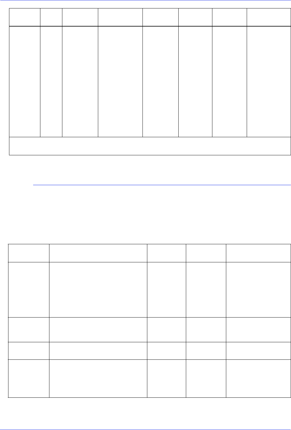
Installation Planning Guide A-19
Supplies
Complete supplies list for the printer
The following table lists the supplies in addition to paper that are
available for your printer. Use this table to help you determine your
supplies needs.
Table A-8 Complete supplies list for the printer
8.5 in. x
14 in. *2
3
N/A
N/A
N/A
N/A
Reverse/
Straight
Straight
N/A
N/A
N/A
N/A
Alternating
CB-White
CF-Canary
Alternating
CB-White
CFB-Canary
CF-Pink
CB-White
CFB-Canary
CF-Canary
CF-Pink
5000
5010
5000
5000
5000
5000
2500
1670
N/A
N/A
N/A
N/A
30
30
30
30
30
30
3R4228
3R4233
3R4237
3R4241
3R4246
3R4247
Pitch Parts Sequence Sheets Sheets
per carton Sets per
carton Cartons
per pallet Part number
* All papers are packaged 500 sheets per ream, with 10 reams per carton. Each ream contains only
complete carbonless sets (i.e., 501 sheets in a three-part ream for 167 sets).
Item Description Part
number Items /
carton Expected yield /
carton
Dry ink Consumption rate is approximately
one cartridge per 60,000 pages. 6R206 3/carton 180,000 pages/carton
NOTE: Dry ink
(toner) yields are
based on 7% area
coverage. Your yield
may vary, depending
on coverage.
Dry ink,
MICR Packaged 3 cartridges per carton.
Consumption rate is approximately
one cartridge per 60,000 pages.
6R819 3/carton 180,000 pages/carton
Dry ink
waste bottle 93K460
Developer Packaged 2 bottles per carton.
Effective life is approximately one
carton per 1,000,000 pages.
(2 bottles required for
replacement.)
5R161 2/carton 1,000,000 pages/
carton

A-20 Installation Planning Guide
Supplies
Ordering supplies
To avoid unnecessary downtime, always have an adequate
amount of the necessary supplies. To do this, you need to
establish a procedure for checking and ordering supplies. A
supplies checklist is provided at the end of this chapter to help you
with this task. It lists the supplies needed for the printer and
contains a column for you to enter the date when you want to
place the order and a column to record the date of the actual
order. The preceding consumable supplies table contains a list of
Xerox supplies available for the printer.
It is important that you check your supplies regularly and order
before you run out. Plan on approximately five working days for
delivery after placing the order. You can make arrangements to
receive them sooner in emergency situations.
Your Xerox sales representative can help you submit the initial
order of supplies needed for installation. These items include
paper, dry ink, fuser agent, and developer.
Once printer volume is established, planning ahead and buying
Xerox supplies in quantity can save you money. The following
Developer,
MICR Packaged 2 bottles per carton.
Effective life is approximately one
carton per 600,000 pages.
(2 bottles required for
replacement.)
5R573 2/carton 600,000 pages/carton
Fuser agent Packaged 1 bottle per carton.
Consumption rate is approximately
one bottle per 250,000 pages.
8R2955 1/carton 250,000 pages/bottle
Cleaning
supplies Foam-tipped swabs 99P87256
Lint-free towels 35P2163
Magnetic head cleaning kit.
Packaged 2 diskettes per box. 8R3811
1/4-inch (QIC) cartridge head
cleaning kit 9R88432
Hub and Transport Cleaner 99P87486
Diskettes 3.5-inch, double-sided, dual
density, 1.44 MB, unformatted.
Packaged 10 diskettes per box.
8R3704 10/box
1/4-inch
(QIC)
Cartridge
tapes
150 MB blank cartridge tape
8 GB blank cartridge tape
9R84168
109R00510
Item Description Part
number Items /
carton Expected yield /
carton

Installation Planning Guide A-21
Supplies
table is a checklist you can use to keep track of the supplies you
order.
When placing an order, please provide the following information:
• Your customer number (provided by your Xerox
representative)
• Your printer model
• Your supply order, including the following information:
– Item name
– Part number
– Quantity desired
– If your company requires a purchase order for payment of
an invoice, you need to provide the purchase order
number to Xerox at the time you place the order.
To order Xerox paper, transparencies, labels, dry ink, developer,
fuser agent, cartridge tapes, and diskettes, call the Xerox Supply
Center at 1-800-822-2200, weekdays between 7:30 a.m. and 6:00
p.m., Pacific time.
If you prefer, you may mail orders to:
Xerox Corporation
P. O. Box 25075
Santa Ana, CA 92799-5075
To order cleaning supplies, call the Xerox Customer Parts and
Product Support Center at 1-800-828-5881, weekdays between
5:30 a.m. and 5:00 p.m., Pacific time, (U.S. only).
You may also mail cleaning supply orders to:
Xerox Corporation
Parts Marketing Center
Building 214-07S
P. O. Box 1020
Webster, NY 14580
In Canada, call telemarketing for consumable supplies (non-
paper):
• (English) 1-800-668-0199
• (French) 1-800-668-0133
• (Fax) 1-416-733-3086
• (Toronto only) 733-9400
In Europe and other countries, contact your local Xerox
representative.

A-22 Installation Planning Guide
Supplies
Table A-9 Supplies checklist
Use this checklist to help record the supplies and accessories you need, the date you plan to
place the order, and the actual date of the order.
Item Description and part number Quantity Date to
order Date
ordered
Paper
Transparencies
Labels
Dry ink
Developer
Fuser agent

Installation Planning Guide A-23
Supplies
Diskettes
Cleaning supplies
Use this checklist to help record the supplies and accessories you need, the date you plan to
place the order, and the actual date of the order.
Item Description and part number Quantity Date to
order Date
ordered

A-24 Installation Planning Guide
Supplies

Installation Planning Guide B-1
B Xerox support services
Xerox provides many services in support of your printing system.
This appendix contains information on the following services:
• Xerox Customer Service Support Center
• Xerox Printing Systems Customer Support Center (U.S.)
• Xerox Documentation and Software Services (XDSS)
• Operator training
• Xerox Customer Education
• Xerox Font Services
Prior to installation, your sales representative is available to
answer your questions about products, services, or billing. If you
need assistance in resolving application-related problems or
questions, contact your local Xerox representative.
In the U. S., you may call the Xerox Printing Systems Customer
Support Center (described later in this chapter). Your system
analyst is also available to assist you with applications
development.
Xerox Customer Service Support Center
The Xerox Customer Service Support Center provides regular
maintenance care for your printer as well as any necessary
repairs. Call the Service Support Center if your printer has a
hardware-related problem such as poor print quality, repeated
paper jams, or connectivity problems.
Before calling your Customer Service Support Center, make sure
you have tried the corrective actions described in the Operator
Guide. If a problem persists, gather the necessary information and
call your customer service support center.
To report printing system hardware or software problems, contact
your local Xerox representative.
NOTE: This phone number is attached to your printer at
installation time.
In the United States, call 1-800-822-2979 to report printing system
hardware or software problems.
Before contacting service, make note of the following:
• Status code numbers and messages that appear on the user
interface or printer control console

B-2 Installation Planning Guide
Xerox support services
• Indicator lights that are lit
Your call is answered by a representative, who asks you for the
model number of your printing system, and for the following:
• Machine serial number
• Your name
• Company name
• Condition or status of the printing system
The Customer Service Support representative will give this
information to a Customer Service representative, who will call
you back to help you resolve the problem over the phone, or to
give you an estimated time of arrival.
Xerox Printing Systems Customer Support Center (U. S.)
The Xerox Printing Systems Customer Support Center is available
to address your application problems or to direct you to the
appropriate documentation.
The key to effective use of the Xerox Printing Systems Customer
Support Center is correct identification of the problem. Before
calling the center, it is helpful to have the following information
available:
• The correct name of your printing system, such as the Xerox
DocuPrint 2000 Series 180 EPS.
• A list of any error messages
• An explanation of how output is different from what was
expected
• An assessment of whether the symptoms follow a pattern or
occur randomly.
• A list of special conditions that may have caused the problem:
– New applications
– Changes made to the software
– Recent service performed
– Previous conditions under which the application has
printed properly
U. S. only: To contact the Xerox Customer Support Center, call: 1-
800-821-2797, between the hours of 5:00 a.m. and 5:00 p.m.,
Pacific time.

Installation Planning Guide B-3
Xerox support services
Xerox Documentation and Software Services (U. S.)
Xerox Documentation and Software Services (XDSS) offers a
variety of services that can be customized to meet your
documentation needs.
XDSS distributes the documents you need to facilitate the
installation and use of the Xerox DocuPrint 2000 Series 100/115/
135/155/180 EPS, other Xerox printers, and associated software.
To order documents, contact your local Xerox representative or
call XDSS at 1-800-327-9753, between the hours of 6:00 a.m. and
5:00 p.m., Pacific time.
XDSS representatives will explain the services available, answer
your questions, and take orders for documentation.
XDSS also has a web site from which you can order customer
documentation. The web site address is:
http://www.xdss.com
Operator training
Operator training is conducted at your location by your Xerox
system analyst or other identified representative, shortly after the
printing system is installed. Training takes two to four hours,
depending on the system configuration. It includes hands-on
practice running basic jobs, performing routine maintenance, and
solving problems. Determine the number of operators you want to
attend the initial training and schedule training dates and times
through your Xerox sales representative.
Additional training classes, such as Advanced Customer Training
(ACT) for operators, teach advanced service and maintenance
skills. Your sales representative can give you information on
availability of ACT training.
A variety of classes and workshops are available through Xerox
Customer Education (refer to the following section).
Xerox Customer Education
Xerox offers classes and tutorial documents on various topics
relating to printing systems and document production. For
information about Xerox training courses, contact your local Xerox
representative. In the U. S., call Xerox Customer Education at 1-
800-445-5554. Customer Education has a web site where you can
obtain additional information. The web site address is:
http://www.xerox.com/go/xrx/customer_education_services/
cust_edu.jsp

B-4 Installation Planning Guide
Xerox support services
Xerox Font Services
The Xerox Font Center can send you samples and catalogs of the
fonts available for your printing system.
To receive font samples, obtain price information, obtain technical
support, or order licensed or custom fonts, contact your local
Xerox representative.
In the U. S., call 1-800-445-FONT (-3668) between 8:30 a.m and
5:00 p.m. Pacific time to receive font samples, obtain price
information, or order licensed or custom fonts. For technical
support regarding fonts (such as installing fonts or solving font
usage problems), call 1-800-521-8324.
Xerox Font Services has a web site where you can obtain
additional information or order fonts. The web site address is:
http://www.font.net

Installation Planning Guide C-1
C Related publications
The Xerox DocuPrint 100/115/135/155/180 EPS documentation
set includes the publications that are listed in the following
sections. Refer to the “Xerox support services” appendix of this
guide for information on how to order these and other
publications.
DocuPrint 100/115/135/155/180 EPS documentation
The following documents contain information on the Xerox
DocuPrint 100/115/135/155/180 EPS:
• Xerox DocuPrint 100/115/135/155/180 EPS Customer
Documentation CD
• Xerox DocuPrint 100/115/135/155/180 EPS Operator Guide
• Xerox Document Services Platform Using LCDS Print
Description Language
• Xerox DocuPrint 100/115/135/155/180 EPS Installation
Planning Guide
• Xerox DocuPrint 100/115/135/155/180 EPS NPS/IPS
Extension Operations Guide
• Xerox DocuPrint EPS Font Reference Manual
• Xerox DocuPrint 100/115/135/155/180 EPS Operator Quick
Reference Card
• Xerox DocuPrint 100/115/135/155/180 EPS Customer
Information Quick Reference Card
• Xerox DocuPrint 100/115/135/155/180 EPS Job Submission
Quick Reference Card
• Generic MICR Fundamentals Guide
• Xerox Document Services Platform System Guide
NPS/IPS publications
For customers who have the NPS/IPS Extension configuration
and are using the Network Printer Series software, the following
related publications are available:
•Xerox DocuPrint 96/4635/180 NPS/IPS V8.0 Interactive
Customer Documentation CD

C-2 Installation Planning Guide
Related publications
•Xerox DocuPrint 96/4635/180 NPS/IPS System Overview
Guide
•Xerox DocuPrint 96/4635/180 NPS/IPS Guide to Performing
Routine Maintenance
•Xerox DocuPrint 96/4635/180 NPS/IPS Troubleshooting Guide
•Xerox DocuPrint 96/4635/180 NPS/IPS Master Index
•Xerox DocuPrint 96/4635/180 NPS/IPS Installation Planning
Guide
•Xerox DocuPrint 96/4635/180 NPS/IPS Customer Information
Quick Reference Card
•Xerox DocuPrint NPS/IPS Guide to Configuring and Managing
the System
•Xerox DocuPrint NPS/IPS Guide to Submitting Jobs from the
Client
•Xerox DocuPrint NPS/IPS Guide to Managing Print Jobs
•Xerox DocuPrint NPS/IPS Guide to Using Page Description
Languages
•Xerox DocuPrint NPS/IPS Solutions Guide for IPDS Printing
•Xerox DocuPrint NPS/IPS Decomposition Service and Tools
Guide
•Xerox DocuPrint NPS/IPS Glossary

Installation Planning Guide I-1
Index
B
back panel, controller
Sun Blade 1000/2000 7
Sun Blade 2500 8
Sun W1100z 8
bypass transport 3, 9
C
cable
lengths 1
locations 1
cartridge tapes 13
CE mark viii
channel-attached connectivity 6
channel-attachments 2
client hardware 4
client networking software 5
components
controller 1
Sun Blade 1000/2000 2
Sun Blade 2500 4
Sun W1100z 4
printer 1
system 2
configurations 2
printer 6
connections 3, 1
connectivity 7, 5
channel-attached 6
Ethernet 5
Token Ring 5
control console 3, 1
controller 3
back panel
Sun Blade 1000/2000 7
Sun Blade 2500 8
Sun W1100z 8
components 1
Sun Blade 1000/2000 2
Sun Blade 2500 4, 6
Sun W1100z 4, 6
environmental specifications 3
interface options 9
outlet configurations 1
overview 1
power requirements 1
space requirements 3
specifications 1, 4
conventions xii
Customer Service Support 1
D
data formats 3
data streams 1
developer 12
diagnostics, remote 8
diskette drive
external 4, 5, 9
diskettes 13
documentation
available 1
NPS/IPS, available 1
DocuSP, remote console GUI 1
dry ink 12
E
environmental specifications
printer 5
Ethernet 5
F
fonts 13
custom 14
licensed 14
MICR, IPS/NPS 6
MICR, LCDS 7
receiving 14
standard 13
fuser agent 12
H
hardware, supported 5

Installation Planning Guide
I-2
Index
I
installation 1
connectivity 5
planning, checklist 3
preparing for 1
process 1
responsibilities 1, 2
interface options
controller 9
online 9
tape drive 10
L
labels 2
laser safety v
licensing, software 3
M
Magnetic Ink Character Recognition, see MICR
maintenance 3
meter reading and reporting 4
routine 3
meter, reading and reporting 4
MICR
dry ink 12
fonts 6
printing features 5
unsupported features 7
O
online interface 9
operating systems, supported 5
operation safety, Europe vii–viii
operation safety, U. S. vi
operator training 3
outlet configurations
printer 2
overview
controller 1
system 1
ozone production information v
P
paper
acceptable stocks, sizes 1
care 9
characteristics 2
conditioning 11
predrilled 2
preprinted 2
recommended weight, grade 1
selecting 1
sizing 3
storing 9
supplies 14
power requirements
controller 1
printer 1
printer 3
bypass transport 3, 9
components 1
configurations 2, 6
control console 3, 1
defining to host 2
outlet configurations 2
power requirements 1
space planning guidelines 14
space planning, templates 26
space requirements 5
specifications 1, 23
specifications, environmental 5
speed 4
publications
available 1
NPS/IPS, available 1
R
remote diagnostics 8
roll feeder support 4
S
safety
hotline numbers vi
laser v
operation vi–viii
ozone v

Installation Planning Guide I-3
Index
software, licensing 3
space
controller 3
planning guidelines 14
requirements, printer 5
specifications
controller 1, 4
controller, environmental 3
printer 1, 23
speed 4, 3
stacker containers 13
Sun Workstation 2
Sun Blade 1000/2000 configuration 2
Sun Blade 2500 configuration 4
Sun W1100z configuration 4
supplies 1
consumable 14
ordering 20
system
components 2
connections 1
overview 1
T
tape drive 10
Token Ring 5
toner 12
training, operator 3
transparencies 2
W
WYE (Star) configurations 3
X
XDSS-Xerox Documentation and Software
Services 3
Xerox Customer Education 3
Xerox Customer Service Support Center 1
Xerox Documentation and Software Services
(XDSS) 3
Xerox Font Services 4
Xerox Printing Systems Customer Support
Center 2
Xerox support services 1

Installation Planning Guide
I-4
Index
