Xerox 4450 Users Manual 4050/4090/4450/4650 Laser Printing Systems Forms Creation Guide XDDI
4650 to the manual b7031d55-1375-ae04-3151-8a6055e860e2
2015-01-23
: Xerox Xerox-4450-Users-Manual-308878 xerox-4450-users-manual-308878 xerox pdf
Open the PDF directly: View PDF ![]() .
.
Page Count: 108 [warning: Documents this large are best viewed by clicking the View PDF Link!]
- Table of contents
- Introduction
- Basic concepts
- Forms Description Language
- Compiling and printing forms
- Troubleshooting
- A. FDL command syntax summary
- B. System default summary
- C. Sample form creation
- D. FDL capacity limits
- E. Standard print formats
- F. Support tools and measurements
- G. Command examples
- Glossary
- Index

Xerox 4050/4090/4450/4650
Laser Printing Systems
Forms Creation Guide
April 1995
720P93990

Xerox Corporation
701 S. Aviation Boulevard
El Segundo, CA 90245
© 1991, 1992, 1993, 1994, 1995 by Xerox Corporation. All rights
reserved.
Copyright protection claimed includes all forms and matters of
copyrightable material and information now allowed by statutory
or judicial law or hereinafter granted, including without limitation,
material generated from the software programs which are
displayed on the screen, such as icons, screen displays, looks,
etc.
Printed in the United States of America
Publication number: 720P93990
Xerox® and all Xerox products mentioned in this publication are
trademarks of Xerox Corporation. Products and trademarks of
other companies are also acknowledged.
Changes are periodically made to this document. Changes,
technical inaccuracies, and typographic errors will be corrected in
subsequent editions.
This document was created on the Xerox 6085 Professional
Computer System using GlobalView software. The typeface is
Optima.
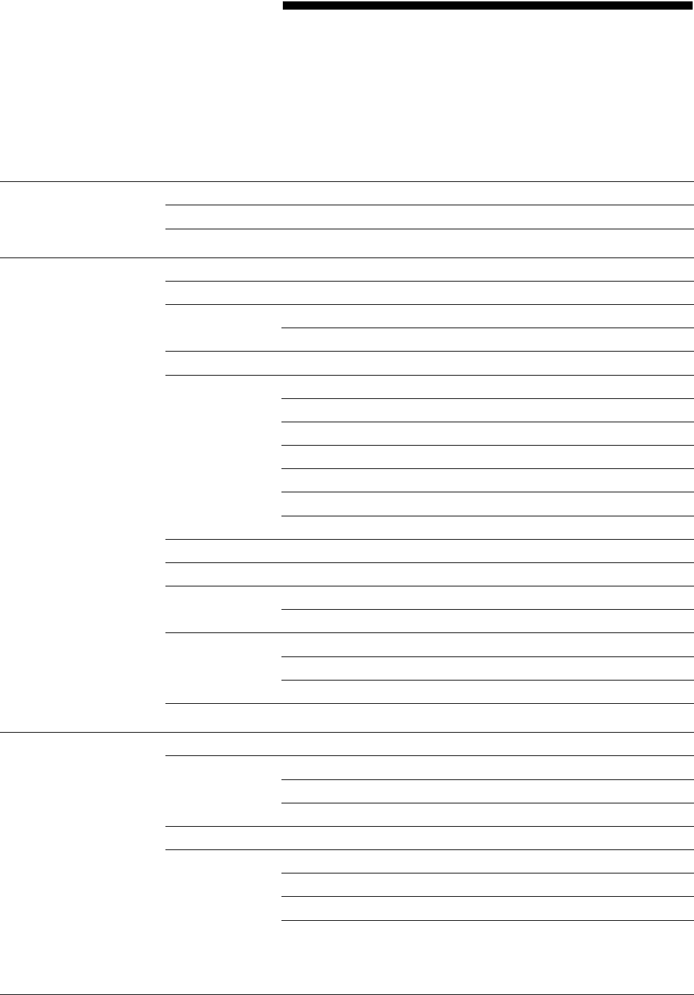
Table of contents
Introduction vii
Document conventions vii
Related publications viii
1. Basic concepts 1-1
Page orientation 1-2
Fonts 1-2
Font memory 1-4
Paper 1-4
Image size considerations 1-4
System page 1-4
Physical page 1-5
Virtual page 1-5
Edgemarking 1-6
Non-imaged elements 1-7
Imaging error messages 1-7
Registration shift and skew 1-7
Output performance considerations 1-9
Form origin 1-10
Positioning form elements 1-11
Grids 1-12
x and y coordinates 1-12
Predefined formats 1-13
Data types 1-14
2. Forms Description Language 2-1
FDL command overview 2-1
Command format 2-1
Command summary 2-2
Form creation process 2-3
Setup commands 2-3
FORM/RESOLUTION 2-4
PAPER 2-5
LANDSCAPE/PORTRAIT 2-6
XEROX 4050/4090/4450/4650 LPS FORMS CREATION GUIDE iii
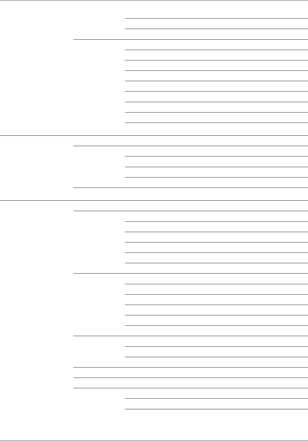
TABLE OF CONTENTS
GRID 2-7
FONT 2-8
Description commands 2-9
LINE 2-10
BOX 2-11
TEXT 2-13
LOGO 2-17
GRAPHIC 2-18
SECTION 2-19
COMMENT 2-21
END 2-22
3. Compiling and printing forms 3-1
Form printing process 3-1
FSL data transfer 3-1
Compiling a form 3-2
Using the compilation options 3-4
Printing a compiled form 3-6
4. Troubleshooting 4-1
Suggested coding techniques 4-1
Converting preprinted forms 4-1
Designing new forms 4-1
Recommended coding sequence 4-2
Syntax ambiguities 4-2
Hints and tips 4-3
Image complexity factors 4-4
Line tables 4-4
Scan line density 4-6
Superimposed lines 4-8
Page generation errors 4-8
Local density and page setup errors 4-8
Using boxes 4-9
Text in boxes 4-10
Locating the closest box 4-10
Shading factors 4-12
Section factors 4-13
Rounding measurement factors 4-14
Converting other unit values to dots 4-14
Rounding variable data 4-15
iv XEROX 4050/4090/4450/4650 LPS FORMS CREATION GUIDE

TABLE OF CONTENTS
FDL statistics 4-16
Grid unit scaling 4-16
Appendices A. FDL command syntax summary A-1
B. System default summary B-1
C. Sample form creation C-1
D. FDL capacity limits D-1
E. Standard print formats E-1
F. Support tools and measurements F-1
G. Command examples G-1
Glossary GLOSSARY-1
Index INDEX-1
XEROX 4050/4090/4450/4650 LPS FORMS CREATION GUIDE v

Introduction
The Xerox 4050/4090/4450/4650 LPS Forms Creation Guide
describes the use of Forms Description Language (FDL)
commands you use to create forms for merging with variable
data to print on a laser printing system (LPS). Descriptions
include the following:
• FDL commands necessary to create any desired form with the
correct page orientation, fonts, line widths, and positioning
of captions and logos
• Fundamental printing terms, techniques, and troubleshooting
• Support tools used to simplify the creation of forms
• Command and default summaries, examples, limitations, and
capacities.
Document conventions
This guide uses the following conventions:
UPPERCASE BOLD BLUE Uppercase bold blue text indicates required characters or
command keywords.
UPPERCASE BLUE ITALICS Uppercase blue italics indicate optional parameter keywords,
characters, or values.
Lowercase black italics Lowercase black italics indicate variable parameter options,
(word, character, phrase, or value).
... Ellipses indicate that you can repeat a parameter option, or list a
series of parameter options.
<> Angle brackets indicate keys on the system controller keyboard.
The carat character represents a required space.
TERMINAL FONT Terminal or monospace fonts are used to represent LPS screen
responses.
UPPERCASE Uppercase letters indicate command names and parameter
keywords.
CAUTION: Cautions appear immediately before any action or omission that
may result in damage to your equipment, software, or data.
WARNING: Warnings are associated with the safety of people.
XEROX 4050/4090/4450/4650 LPS FORMS CREATION GUIDE vii

INTRODUCTION
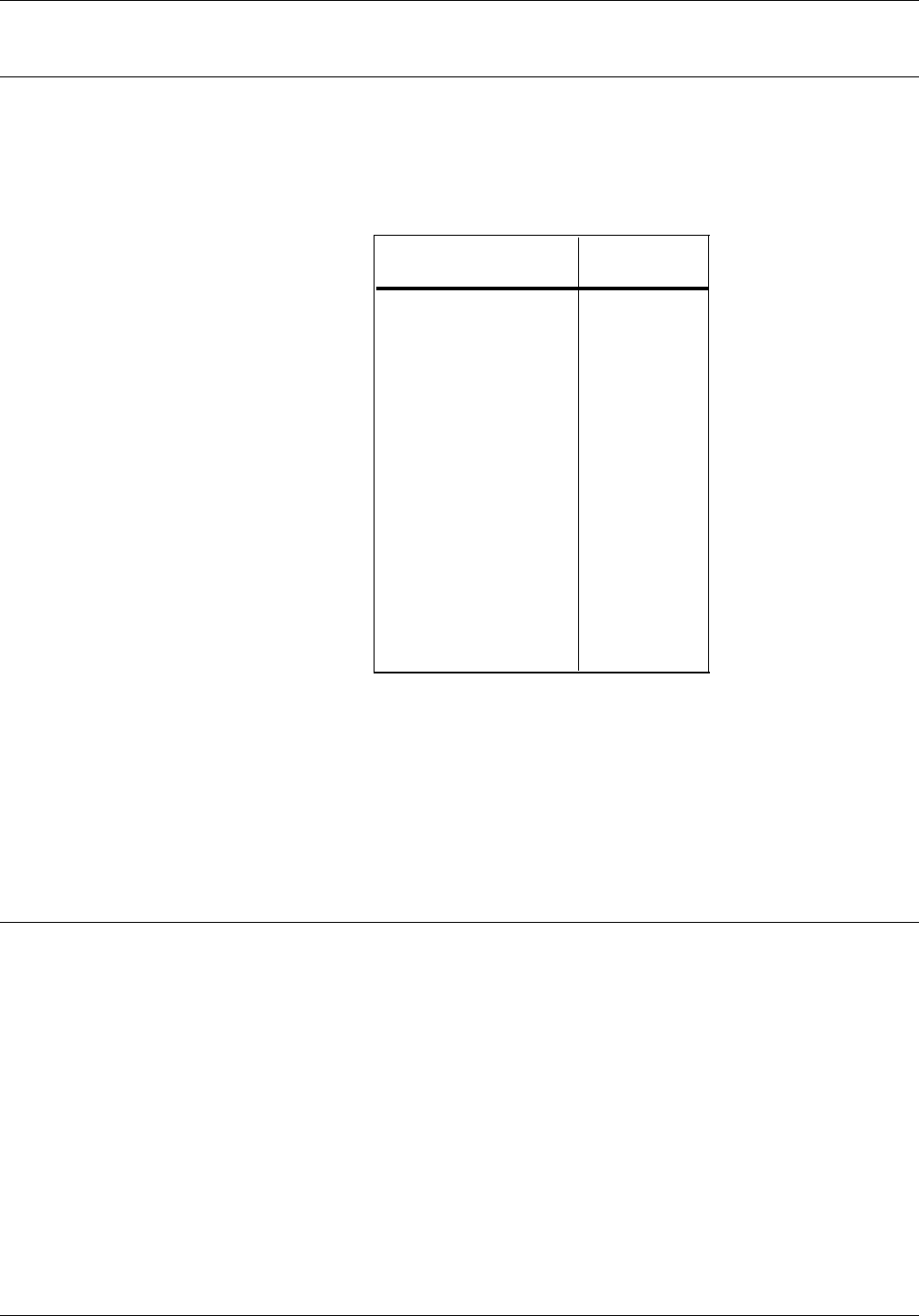
Related publications
You can find additional information related to the
4050/4090/4450/4650 LPS in the following publications.
Publication Number
Xerox 4050/4090/4450/4650 LPS Master Index 720P94030
Xerox 4050/4090/4450/4650 LPS Bypass
Transport Instructions, V3.5/3.8 720P22320
Xerox 4050/4090/4450/4650 LPS Bypass
Transport Operator Training Guide Flipcharts
Supplement
720P22340
Xerox 4050/4090/4450/4650 LPS Bypass
Transport Operator Training Guide
Supplement
720P22330
Xerox 4050/4090/4450/4650 LPS Command
Reference 720P94020
Xerox 4050/4090/4450/4650 LPS Forms
Creation Quick Reference Card 720P93100
Xerox 4050/4090/4450/4650 LPS Installation
Planning 720P92990
Xerox 4050/4090/4450/4650 LPS Message
Guide 720P93980
Xerox 4050/4090/4450/4650 LPS Operator
Guide 720P94000
Xerox 4050/4090/4450/4650 LPS Operator
Instructor Training Flipcharts 720P22080
Xerox 4050/4090/4450/4650 LPS Operator
Instructor Training Guide 720P22070
Xerox 4050/4090/4450/4650 LPS Operator
Quick Reference 720P93050
Xerox 4050/4090/4450/4650 LPS Print
Description Language (PDL) Quick Ref. Card 720P93090
Xerox 4050/4090/4450/4650 LPS Print
Description Language (PDL) Reference 720P94090
Xerox 4050/4090/4450/4650 LPS Product
Reference 720P94060
Xerox 4050/4090/4450/4650 LPS System
Administration Guide 720P94010
Xerox 4050/4090/4450/4650 LPS System
Administration Quick Reference Card 720P93090
Xerox Standard Font Library Font User Guide 600P86174
Xerox Tape Formats Manual 600P86175
Helpful Facts About Paper 610P50497
Xerox Dynamic Document Interface
Command Summary 720P13680
Xerox Dynamic Document Interface
Operator Guide 720P13670
viii XEROX 4050/4090/4450/4650 LPS FORMS CREATION GUIDE

1. Basic concepts
The laser printing system (LPS) provides the capability to create
electronic forms tailored to meet your individual requirements.
You create electronic forms using the Forms Description
Language (FDL). This simple-to-learn, easy-to-use language
enables you to design and alter forms in minutes.
FDL-defined forms are input to the printer as data, using the LPS
keyboard and display, or a host computer terminal. To define a
form, FDL uses lines, logos, images, signatures, shading, and
different font styles and sizes to make full use of laser printing
system features and capabilities.
Advantages of FDL • Lines can be drawn at specified intervals without being
redefined each time.
• You state the origin and the dimensions of a box to have it
drawn at any specified location on the page.
• An entire section of a form, once defined, can be repeated
anywhere on the same form.
• In defining a location on a page, you are not restricted to
lines and character positions. You can specify coordinates in
inches, centimeters, or dots with a resolution of 1/300 inch in
either direction.
Note: An xdot is a 1/600 inch unit of measure that is
provided with version 3 software. A form specifying xdots
may be created, edited, and compiled on any V3-based LPS.
However, results are unpredictable if you attempt to print a
600 spots per inch (spi) form on a 300-spi LPS.
• Once you create a form, it can be stored on the system and
printed as many times and as often as you need.
• You can use three types of lines (solid, broken, and dotted)
in four thicknesses: invisible [0], hairline, medium [1], or
bold [2]. You can also mix fonts and arrange text in many
ways.
Certain basic concepts are required to understand the forms
creation process on laser printing systems. These include the
size, shape, and location of the overall image on the page of a
document, the orientation of the text or graphics on the page,
the size and style of the characters to be used, and the type of
data to be entered.
This chapter discusses fonts and font memory, registration and
skew, and output information for the jobs you create on your
LPS.
XEROX 4050/4090/4450/4650 LPS FORMS CREATION GUIDE 1-1
BASIC CONCEPTS
Page orientation
There are two types of page, or text, orientation:
• Portrait
• Landscape.
In portrait orientation, the vertical side of the page is longer than
the horizontal side. In landscape orientation, the horizontal side
of the page is longer than the vertical side. Portrait and
landscape orientations are illustrated in figure 1-1.
Figure 1-1. Page orientation
PORTRAITLANDSCAPE
Landscape is the usual orientation for computer reports. Portrait
is the usual orientation for letters, manuals, and other text
printing. On a laser printing system, you can change page
orientation from page to page without interrupting the printing
operation. This capability, coupled with variable character size,
permits maximum flexibility for the effective presentation of
information.
Fonts
A font is a character set which has a unique type style, type size,
and orientation.
Fixed and proportional fonts Both fixed and proportionally spaced fonts are available for use
on the 4050/4090/4450/4650 LPS. Each font character occupies
an area called a character cell. All character cells in a fixed font
are the same width. Character cells in a proportional font vary in
width.
Figure 1-2. Character spacing
1-2 XEROX 4050/5090/4450/4650 LPS FORMS CREATION GUIDE

BASIC CONCEPTS
Because the length of a line printed with a proportional font is
unpredictable, the system uses fixed fonts for variable data on a
report to avoid overprinting of forms by variable data. The
system uses proportional fonts for forms data such as titles,
headings, and so forth. A business letter is an example of the
use of proportional fonts for variable data. Figure 1-3 shows an
example of the difference in line length.
Figure 1-3. Character spacing/line length examples
Font typefaces Fonts are available in various typefaces (such as OCR and Titan),
sizes, styles (such as serif and sans serif), and weights (such as
medium and bold). The Xerox LPS Standard Font Library Font
User Guide lists the standard fixed and proportional fonts.
Font orientation In addition to typeface, style, and size, a font can be defined by
its orientation:
• Landscape
• Portrait
• Inverse landscape
• Inverse portrait.
Font orientation is relative to the physical page.
Figure 1-4. Font orientation
Refer to the Xerox Laser Printing Systems Standard Font Library
Font User Guide for specific font information and the Xerox
4050/4090/4450/4650 LPS System Administration Guide for
information on using Font Editor keyword commands to create
source font files from existing licensed and nonlicensed font
files.
XEROX 4050/5090/4450/4650 LPS FORMS CREATION GUIDE 1-3

BASIC CONCEPTS
Font memory
Increasing font memory improves processing time for
applications that require large fonts or a large number of
different fonts on a single page. In the pass through mode, the
LPS prints up to 128 fonts on a single page. In normal mode,
the amount of fonts per page that the LPS prints depends on the
font definitions for the emulated line printer. When processing
the page data, the controller stores font information in a special
memory cache called font memory. The amount of memory
required to store font data depends on the size of the fonts and
the number of different fonts on a single page.
If your applications call for either large fonts, or a variety of fonts
on a single page, the increased font memory option can greatly
improve the processing time required to print these documents.
Custom fonts, logos, and signature font data also consume font
memory during processing.
Paper
Paper sizes Laser printing systems print on the following paper sizes:
• 8.5 by 11 inch (216 by 279 mm)
• A4 (8.27 by 11.69 inch, 210 by 297 mm)
• 8.5 by 14 inch (216 by 356 mm).
Paper types A large variety of paper types can also be used on the LPS:
• Label stock
• Transparencies
• Predrilled
• Perforated
• Colored.
Paper weights and printing speed vary with each printer.
Image size considerations
Your LPS can print on a variety of paper sizes. You can
manipulate the size of the image with some limitations.
Understanding the terms system page, physical page and virtual
page helps to define these limitations.
System page
This refers to the maximum image area, which is 8.6 by 14.00
inches. Elements which do not print may originate off the
leading edge of the system page.
Refer to the “Non-imaged elements” subsection later in this
chapter for more information.
1-4 XEROX 4050/5090/4450/4650 LPS FORMS CREATION GUIDE
BASIC CONCEPTS
Physical page
This refers to the size of the paper itself. You can use any page
dimension as long as the paper physically fits in the feeder trays
and you can preselect the following paper sizes at system
generation (sysgen), as shown in table 1-1.
Table 1-1. Physical page sizes
Inches Millimeters
8.0 x 10.0 203 x 254
8.0 x 10.5 203 x 267
8.0 x 13.0 203 x 330
8.27 x 10.63 210 x 270
8.27 x 11.69/A4 210 x 297
8.27 x 13.0 210 x 330
8.37 x 10.78 213 x 274
8.46 x 10.83 215 x 275
8.46 x 12.4 215 x 315
8.46 x 14.02 215 x 356
8.5 x 10.75 216 x 273
8.5 x 11.0/USLETTER 216 x 279
8.5 x 13.0 216 x 330
8.5 x 14.0/USLEGAL 216 x 356
Use the PAPERSIZE command in the Print Description Language
(PDL) and the PAPER command in the Forms Description
Language (FDL) to allow form compilation and job printing on a
size of paper other than the paper size you select at sysgen. This
allows you to specify nonstandard paper size for specific jobs.
Refer to the “Forms Description Language” chapter and the
Xerox 4050/4090/4450/4650 LPS Print Description Language (PDL)
Reference for more information about commands.
Virtual page
The virtual page refers to the dimensions of the page as specified
in the software. The dimensions of the virtual page may be less
than or equal to the dimensions of the physical page size, but
not larger. The printer truncates larger values.
If you explicitly define virtual page size (using the
LANDSCAPE/PORTRAIT command PAGE SIZE parameter), the
defined area is centered relative to the physical page dimensions.
You can specify an orientation for the virtual page either with the
LANDSCAPE/PORTRAIT command or by using the FMTn option of
the GRID command. If an orientation is not specified, the virtual
page is assigned a landscape orientation by default.
XEROX 4050/5090/4450/4650 LPS FORMS CREATION GUIDE 1-5
BASIC CONCEPTS
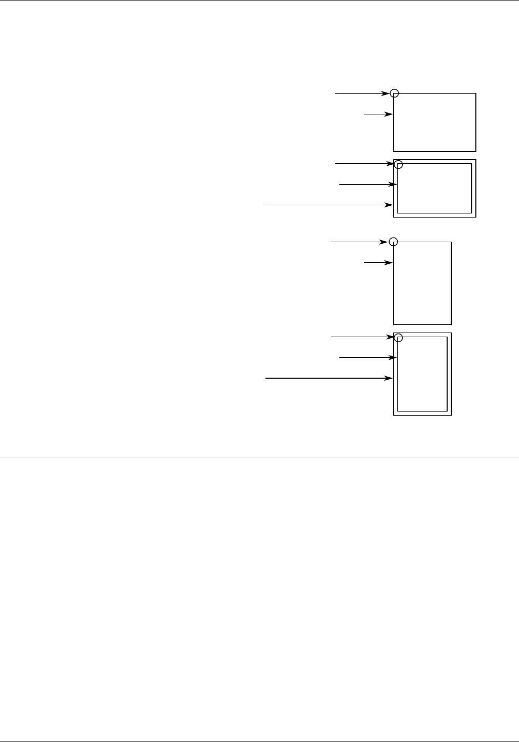
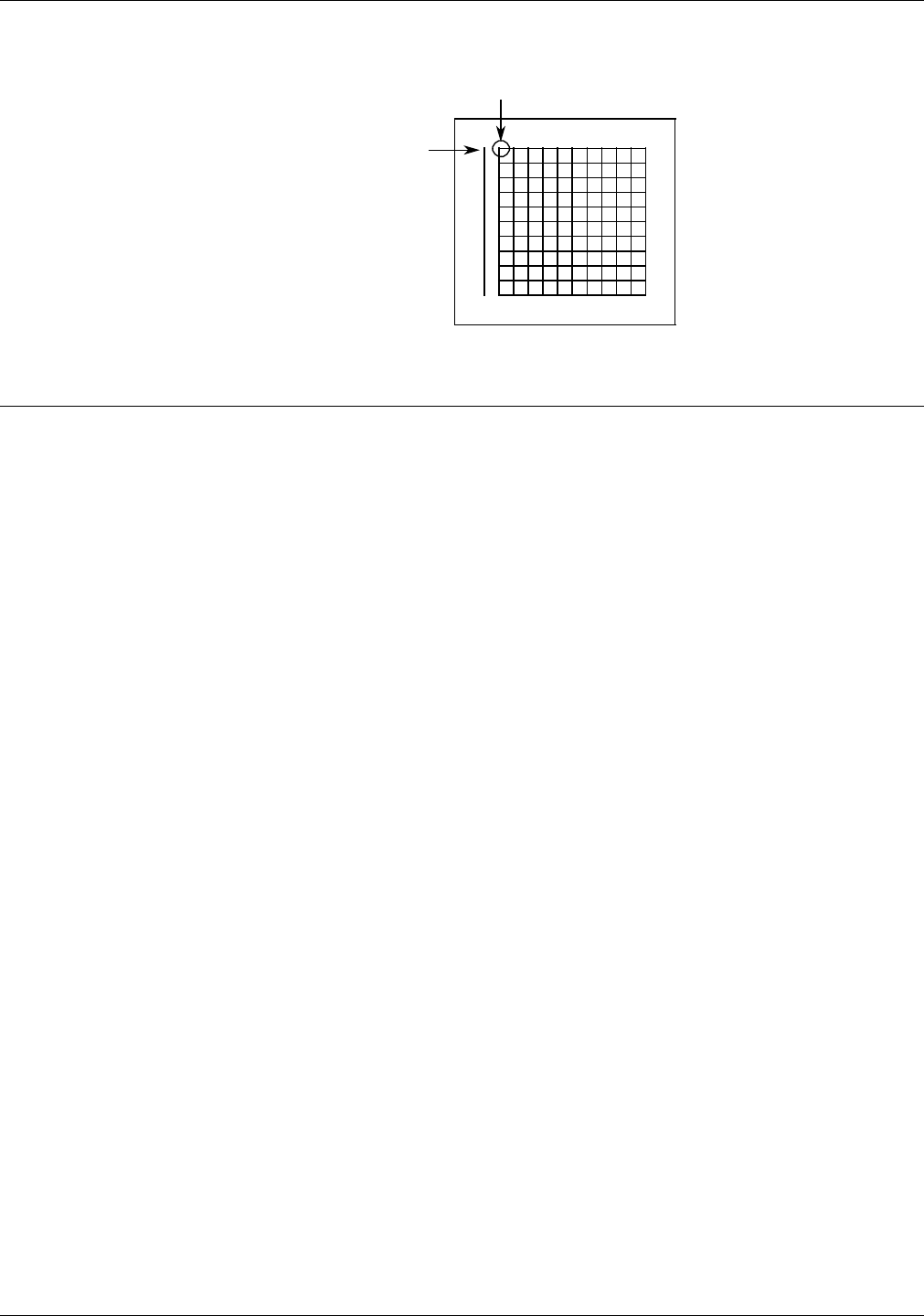
The upper left corner of the virtual page is called the “virtual
page origin,” as shown in figure 1-5. The virtual page origin is
also used to establish a form origin.
Figure 1-5. Virtual page origin
LANDSCAPE virtual page origin
Virtual page (default size=paper size)
LANDSCAPE virtual page origin
Virtual page (user-defined size)
Physical page
PORTRAIT virtual page origin
Virtual page (default size=paper size)
PORTRAIT virtual page origin
Virtual page (user-defined size)
Physical page
Edgemarking
The same coordinate system is used for printing on all Xerox
printers. This limits the printing area in some cases and can
cause you to lose data which begins near, or off, the edge of the
physical page.
Edgemarking is the placement of marks along the edge of the
page. These marks consist of graphic elements that bleed off the
paper, tabs for section reference, or marks that denote changes
made in redline drafts.
To accommodate edgemarking, the system page must be larger
than the physical page. Edgemarking capability is limited on the
LPS because the system page boundaries (such as the 8.6 by 14
inch maximum image size printing area) correspond to the
physical page on at least two edges for all paper sizes.
CAUTION: Be careful when edgemarking. Printing a solid band
on the leading edge of the paper may cause fuser jams.
1-6 XEROX 4050/5090/4450/4650 LPS FORMS CREATION GUIDE

BASIC CONCEPTS
Non-imaged elements
Elements, such as text and graphics, may begin at the edge of
the physical page on two sides, and off the physical page on the
top and on the left side (except with 8.5 by 14 inch paper).
However, if any part of a printed element begins off the system
page, no part of the element images.
• If a line of variable data begins off the system page, no part
of the line prints.
• If a ruled line begins off the system page, no part of the
ruled line prints.
• A ruled line near the edge of the system page must hold a
position of at least one-half the line thickness inside the
system page to print. For example, a bold line is eight dots
thick and, therefore, it must hold a position of at least four
dots inside the system page leading edge.
One common cause of print elements accidentally beginning off
the system page is the improper use of the OUTPUT SHIFT
command. This command shifts the entire page contents relative
to the boundaries of the system page. When you enter a
negative shift value (as is often the case for the back side of
duplex pages), and that value exceeds the left margin, no text
element prints. When using a negative value for the SHIFT
command, be sure that it is less than the value of the left margin.
Imaging error messages
If any part of a print line originates off the system page, the
following message displays:
OS6905 DATA ORIGIN OFF PAGE -- CHECK OUTPUT
This message line appears only once during a print job. It
indicates that a print line origin problem exists within the form
description, or that an excessive SHIFT value has been specified.
Registration shift and skew
The registration of a printed image can appear shifted or skewed
on a page if the sheet of paper is misaligned as it enters the
printer. Because of the design of the LPS feeder, the image
registration on each page can vary slightly both horizontally and
vertically by up to .05 inches (1.0 mm). The image can also slant
or skew slightly by up to .05 inches (1.0 mm) in opposite
directions, for a maximum skew of 0.1 inches (2.0 mm).
Note that the following figures are the same specifications which
have been rotated to show portrait and landscape orientations.
The shift and skew variances described here are within allowable
specifications. However, as this can affect the registration of
variable data in preprinted forms and the placement of images
close to the edge of the page, it is important to make allowances
for this condition.
XEROX 4050/5090/4450/4650 LPS FORMS CREATION GUIDE 1-7
BASIC CONCEPTS
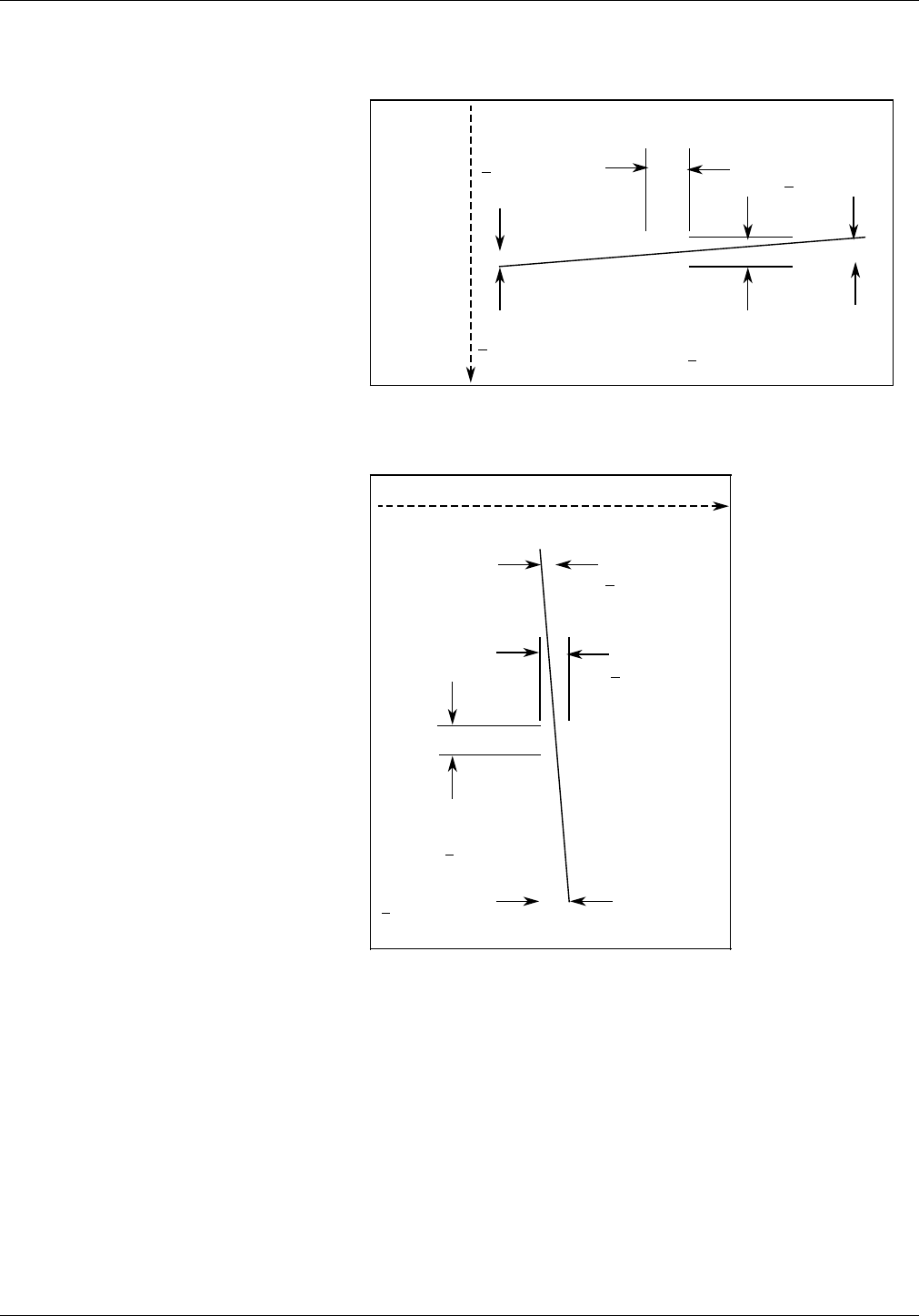
Figure 1-6. Landscape orientation shift and skew
(11 x 8.5 inches)
Lead edge
Registration variance
+ .05“/1.0 mm
Skew
+ .05“/1.0 mm
Direction of
paper feed
Trail edge
Skew
+ .05“/1.0 mm
Registration
variance
+ .05“/1.0 mm
Figure 1-7. Portrait orientation shift and skew
(8.5 x 11 inches)
Inboardside
Skew
+ .05“/1.0 mm
Skew
+ .05“/1.0 mm
Direction of paper feed
Outboardside
Registration
variance
+ .05“/1.0 mm
Registration
variance
+ .05“/1.0 mm
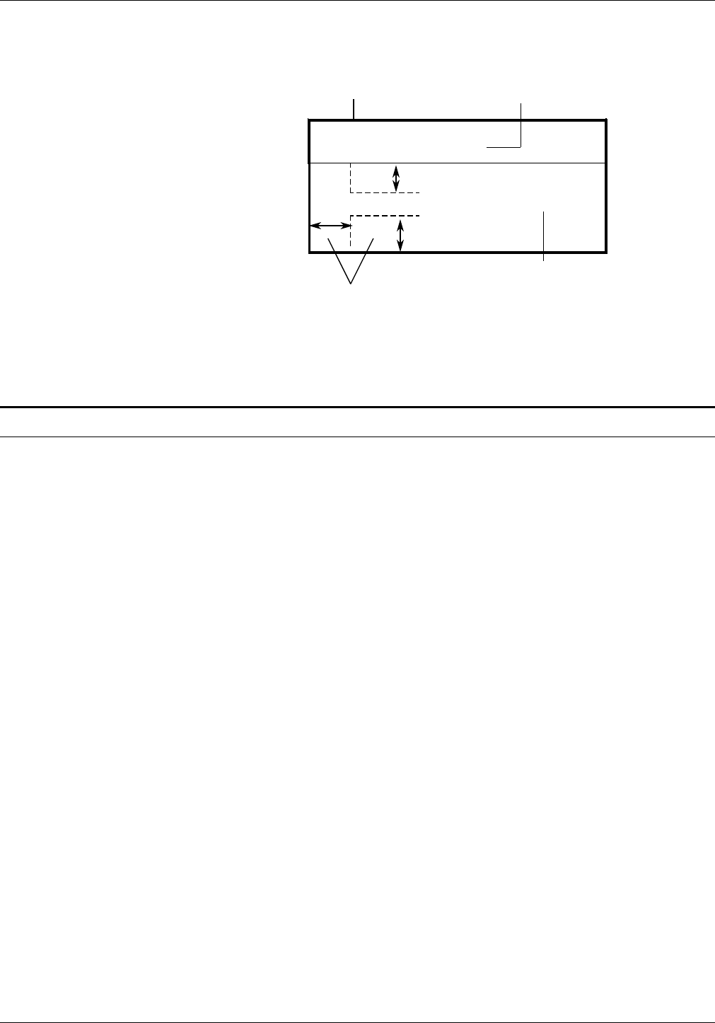
For best results when designing preprinted forms, allow
approximately .1 inches or 2.0 mm of space on all sides of any
boxes, or above and below any lines onto which variable data is
to be printed, as shown in figure 1-8.
1-8 XEROX 4050/5090/4450/4650 LPS FORMS CREATION GUIDE
BASIC CONCEPTS
Figure 1-8. Maintaining margins in preprinted boxes to
allow for registration and skew variations
PATIENT NAME
Preprinted lines
Variable data
Preprinted form data
•
Maintain at least .1“ or 2 mm on all sides around variable data
••
Note: Figure 1-8 is enlarged for the purpose of illustration, and
is not to scale.
Output performance considerations
The LPS has a rated speed of up to 50 (4050, 4450, and 4650) or
up to 92 (4090) impressions per minute (an impression refers to
one printed side of a sheet of paper). The actual output
performance you experience depends greatly on the processing
features invoked in the job and the print density of each page.
Actual output also varies according to the configuration of the
LPS, such as the type of connection (offline, online, remote
communication, and front end processor).
This section provides information on expected output
performance when printing various types of jobs, applications,
and hardware configurations. For more detailed information,
consult your service representative.
Note: The term throughput refers to the print speed once pages
start printing. The processing that occurs prior to the actual
printing of the pages depends greatly on the complexity of the
job.
Interpress Interpress masters sent to the LPS must be processed by the
Interpress decomposer function of the Operating System
Software (OSS). The time required to print an Interpress job
depends on the complexity of the image from page to page.
PostScript PostScript masters sent to the LPS must first be converted to
.IMG files in the front end processor. The time required to print
a PostScript job depends on the complexity of the image from
page to page.
Dynamic Job Descriptor Entries (DJDE) The use of DJDEs adds processing time and slows the output.
To maximize performance, restrict the use of DJDEs to the
following commands: GRAPHIC, FORMAT, MODIFY, and FORM.
XEROX 4050/5090/4450/4650 LPS FORMS CREATION GUIDE 1-9
BASIC CONCEPTS
Print density Full throughput estimates are based on pages with an average
print density of approximately seven percent of the page. Pages
which are very dense require more time to image and to print.
Highlight color The LPS running V3.8 Color Compatibility Release or XDDI
software is compatible with the 4850/4890 printer running V3.7,
V4.0, or V5.0 highlight color software. Highlight color
applications can be printed when using V3.8 or XDDI software on
the LPS. Highlight color datastreams are fully supported and
translate to black and shades of gray.
Color text printed over a solid black background or vice versa,
disappear when printed on the LPS. There is no error message
when this occurs. Light tints with isolated single pixels may not
print on the LPS.
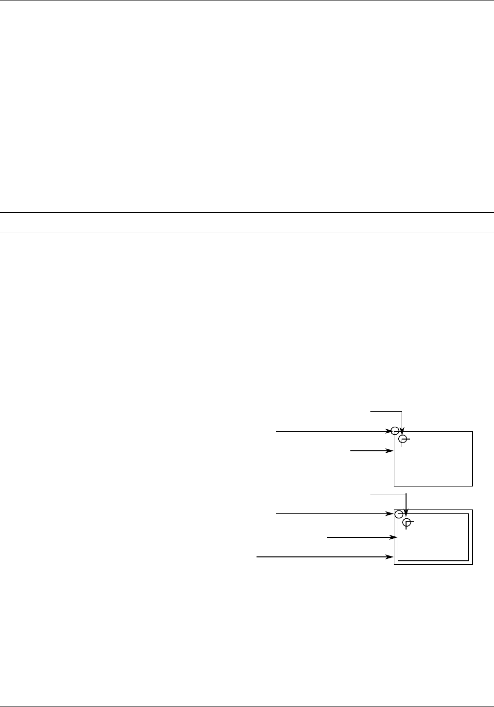
Form origin
All forms data described by FDL commands is positioned relative
to a point called the “form origin,” as shown in figure 1-9. This
point offsets from the virtual page corner by horizontal and
vertical displacement values, which you specify using the GRID
command. If none are specified, standard default values are
used to establish the form origin.
If variable data is merged with the form, set the form origin to
coincide with the beginning position of the variable data so that
the form and variable data coordinate accurately. Standard
computer printing formats are stored on the system. Refer to
the “Predefined formats” section, later in this chapter.
Figure 1-9. Form origin
Virtual page origin
Virtual page (default size=paper size)
Virtual page origin
Virtual page (user-defined size)
Physical page
Form origin (offset from virtual page origin)
Form origin (offset from virtual page origin)
1-10 XEROX 4050/5090/4450/4650 LPS FORMS CREATION GUIDE
BASIC CONCEPTS
Positioning form elements
The following elements may be placed on a form with FDL
commands:
• Lines
• Boxes
• Fixed text
• Logos and signatures
• Images
• Sections.
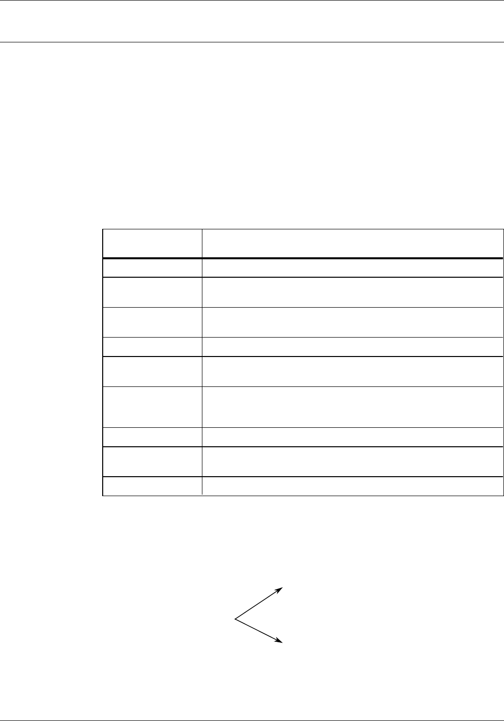
All of these elements are located in relation to the form origin at
the upper left corner of the form. Each form element has an
origin, a point used to position it relative to the form origin, as
shown in table 1-2.
Table 1-2. Form elements and corresponding origins
Form element Element origin
Vertical ruled line Top of the line at the midpoint of the line thickness
Horizontal ruled
line Left end of the line at the midpoint of the line thickness
Box (outlined) Upper left corner of the box at the midpoint of the outline
thickness
Box (shaded) Upper left corner of the box
Fixed text (single
line) Upper left corner of the first character cell
when the line appears upright to the viewer
Fixed text (multiple
lines) Upper edge of the topmost character cell and the leftmost
edge of the leftmost character cell when viewed in an upright
position (illustrated in figure 1-10)
Graphics Upper left corner of the image
Logos and
signatures Upper left corner of the first (or only) character cell (with a few
exceptions)
Sections (of a form) Upper left corner of the section
Figure 1-10 shows two text blocks, one using a portrait font and
one using a landscape font. The text block origin is used to
position the text block relative to the form origin.
Figure 1-10. Text block origin
Origin
XEROX 4050/5090/4450/4650 LPS FORMS CREATION GUIDE 1-11
BASIC CONCEPTS
Grids
The location of a form element on a page is specified in terms of
its horizontal and vertical displacement from the form origin. The
units of measurement used to define this displacement can be
any of the following:
• Linear units—inches or centimeters
• Dots—300 per inch
• Xdots—600 per inch
• cpi and lpi—characters per inch horizontally and lines per
inch vertically.
x and y coordinates
The y coordinate describes the vertical position on a grid. The x
coordinate describes the horizontal position. When both
coordinates are given together, the y coordinate is always
specified first.
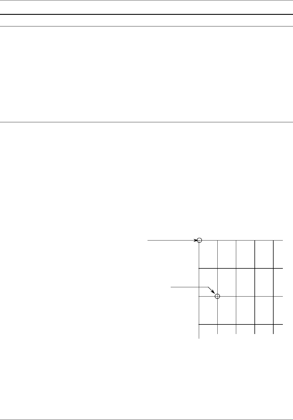
If you draw a horizontal and a vertical line through the form
origin to create x and y coordinates, you would express the
location of the form origin as y=0, x=0.
If you draw more lines to mark horizontal and vertical
measurements away from the form origin so that the lines were
one unit of measurement apart, you create a grid like the one
shown in figure 1-11. You can then position form elements
(lines, boxes, and so on) by specifying a grid location.
Figure 1-11. Form grid
1 3
3
1
2
A
42
Form origin
(y=0,x=0)
Y
Character cell origin at
(y=2,x=1)
X
1-12 XEROX 4050/5090/4450/4650 LPS FORMS CREATION GUIDE

BASIC CONCEPTS
Example You placed the letter “A” at location (2,1). If you are measuring
grid units in inches, the origin of the “A” character cell is located
two inches down and one inch to the right of the form origin. If
you are measuring the grid in cpi and lpi units, the origin of the
“A” character cell is located two lines down and one character
width to the right of the form origin. At 10 cpi and 6 lpi, the “A”
is .33 inches down from the form origin and .10 inches to the
right.
Negative coordinates Negative x and y values also may be used to place form elements
above and/or to the left of the form origin, as long as the values
are within system page boundaries.
UNIT value The unit value of the GRID command specifies the unit of
measurement that the FDL commands use to position form
elements on the page. Optionally, you can select a predefined
format that automatically provides grid unit values. Individual
FDL commands may override GRID unit values.
Predefined formats
A set of predefined print description entries or formats, having
standard format specifications, is provided on the Operating
System Software (OSS) tapes. You may use the standard formats
or define your own to suit your specific needs.
Reference Refer to the “Standard print formats” appendix for a list of the
standard LPS print formats.
These standard formats provide commonly used impact printer
conversion formats for use with specific page sizes and
orientations. Use the Xerox design ruler to assist you in
measuring character and line spacing. The ruler has eight scales
that conform to the standard format grid.
Reference Refer to the “Support tools and measurements” appendix for
more information on the forms design ruler.
FMT1 (landscape) or FMT6 (portrait) is used by FDL to provide
default values for page orientation, form origin, and grid unit
dimensions, provided there are no explicit overriding parameters.
Unless overridden by an explicit orientation PAGE SIZE
parameter, the virtual page size in a predefined format is always
the sysgen-specified paper size. The virtual page origin is located
at the upper left corner of the physical page.
XEROX 4050/5090/4450/4650 LPS FORMS CREATION GUIDE 1-13
BASIC CONCEPTS
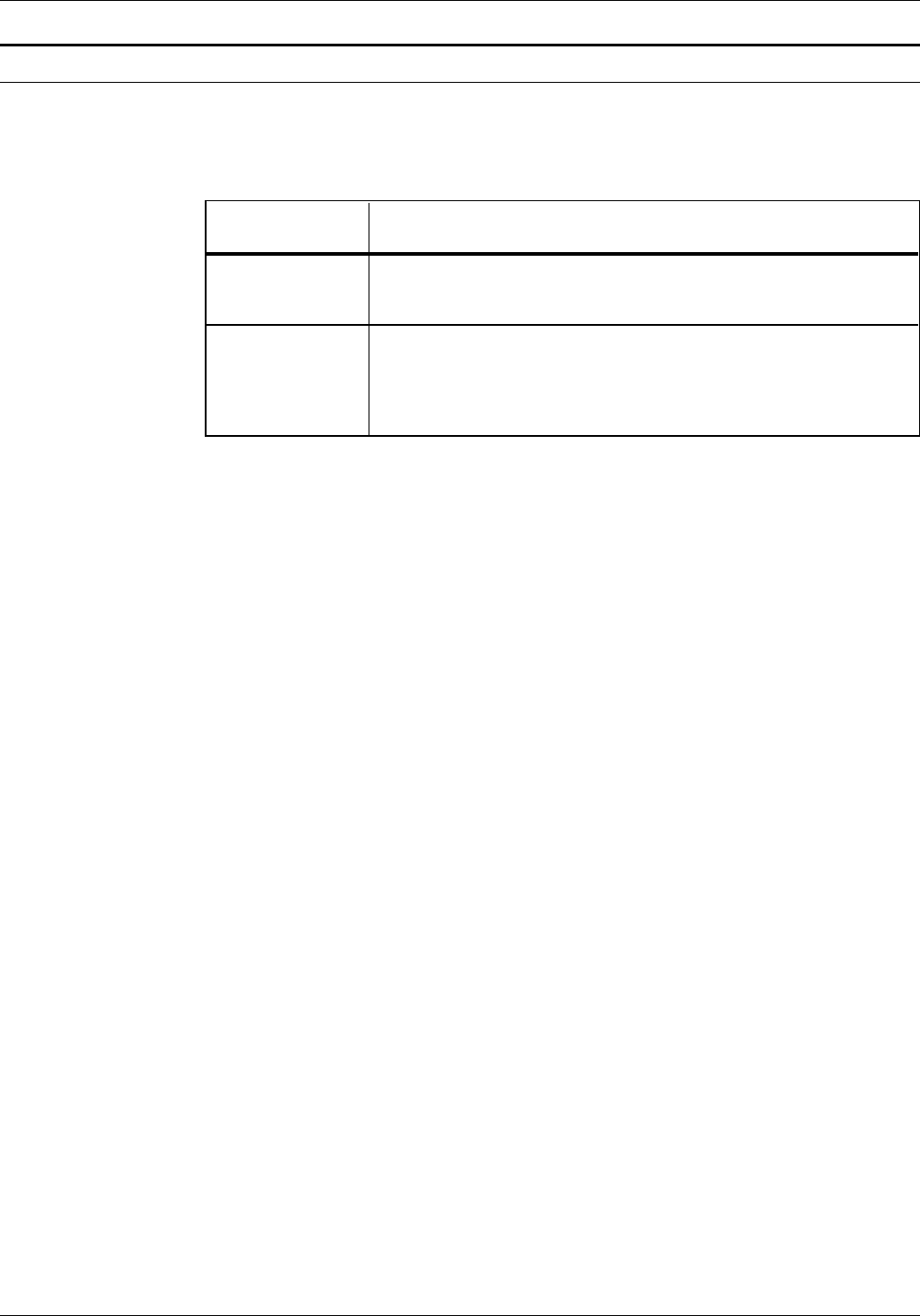
Data types
Two types of data are used in creating and printing LPS forms, as
shown in table 1-3.
Table 1-3. Data types
Data type Description
Variable Generally refers to computer-produced information that the LPS
merges with a form. Typically this data varies from page to
page.
Forms Refers to information that is used to print the form, such as
lines between columns and rows, boxes, and shading. Forms
data also refers to information that is part of the form, such as
titles, headings, captions, logos, and signatures. Forms data
typically does not vary from page to page.
1-14 XEROX 4050/5090/4450/4650 LPS FORMS CREATION GUIDE

2. Forms Description Language
This chapter describes the function and use of each Forms
Description Language (FDL) command in generating a form
electronically.
The FDL commands discussed throughout this guide apply to all
version 3 laser printing systems.
Reference Refer to the “FDL command syntax summary” appendix for a
summary of all FDL commands and their syntax. The conventions
used to present command syntax are listed in the “Introduction”
and in the “FDL command syntax summary” appendix.
FDL command overview
FDL is a set of keyword commands that you use to generate an
electronic form.
You first create a source file of FDL commands that describes the
characteristics of your form. You then compile the file and store
it as an electronic form file on the LPS.
The form can contain a variety of fonts, logos, and graphics, and
it can be merged with variable data during printing. You can
select any stored form for printing.
Command format
The following is true for each FDL command:
• Commands consist of a command identifier and various
parameters and keywords associated with the function.
• Spaces and/or commas separate keywords and parameters.
• Commands are terminated by a semicolon.
• Command information is placed within the first 72 columns
of each record.
• Multiple commands may appear in one record if separated by
a semicolon.
• Commands can be continued on multiple lines before ending
with a semicolon, with the exception of the LINE and BOX
commands. For both of these commands, the following
string must reside on one line:
AT . . . IN unit
Lines containing all blanks are ignored and may be used for
separation.
XEROX 4050/4090/4450/4650 LPS FORMS CREATION GUIDE 2-1
FORMS DESCRIPTION LANGUAGE
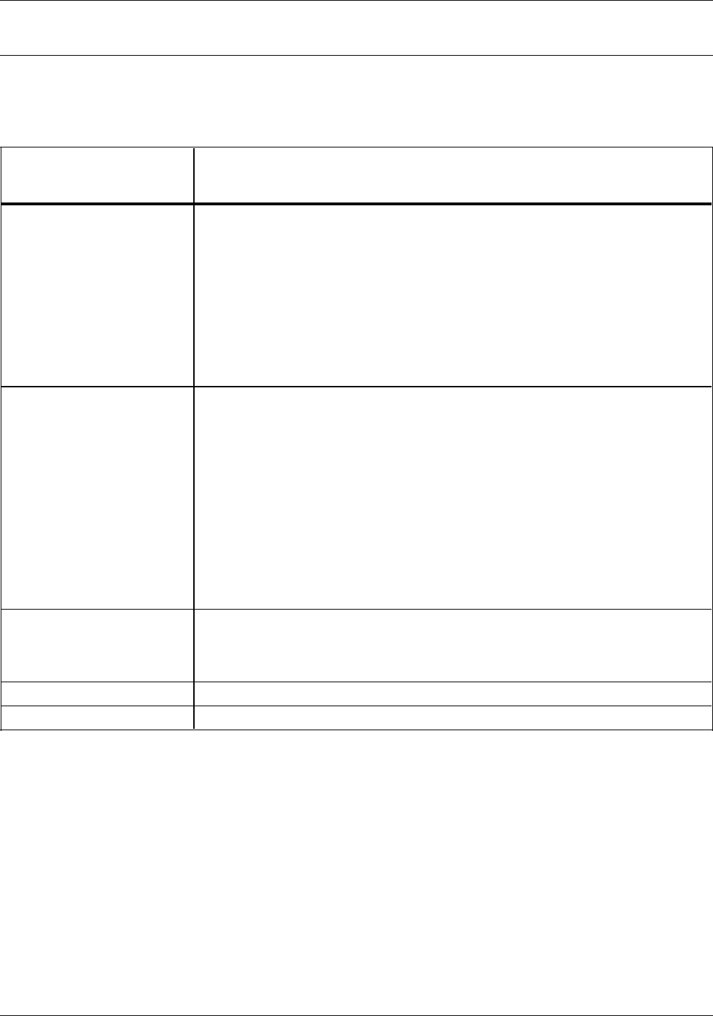
Command summary
The five types of commands and the associated FDL commands
are described in table 2-1.
Table 2-1. FDL command summary
Command types and
commands Command function
FORM/RESOLUTION Identifies the name of a form in the forms library and the resolution at which
the form should be compiled for printing.
PAPER Identifies the paper size for which the form is designed.
LANDSCAPE/PORTRAIT Specifies the page orientation and virtual page size.
GRID Specifies the grid units used in describing the form and the origin of the form
relative to the virtual page origin. In most cases, a standard format
specification can be entered, which provides standard character and line
spacing, page orientation, and form origin.
FONT Specifies which fonts to use when creating a form.
LINE Specifies the length, position, direction, and thickness (hairline, 0, 1, or 2) of
lines.
BOX Specifies the location of the upper left corner and the dimensions of square
or rectangular boxes. All boxes in FDL are fixed-size. Backgrounds for text
must use the BOX command.
TEXT AT Specifies the positioning of text (written matter) such as form titles, headings,
and labels in specific locations.
TEXT IN BOX Specifies the positioning of text in a box.
LOGO Specifies the positioning of logos and signatures.
GRAPHIC Specifies a graphic image to be merged with the form and its placement and
relative scale.
SECTION Defines a portion of a form as a relocatable section.
END SECTION Terminates a section.
DO SECTION Invokes and places a previously defined section of a form.
COMMENT Inserts comments.
END Terminates a form description.
2-2 XEROX 4050/4090/4450/4650 LPS FORMS CREATION GUIDE

FORMS DESCRIPTION LANGUAGE
Form creation process
The following three basic steps are required to produce an
electronic form:
1. Initiate an editing session.
2. Enter the FDL commands.
3. Compile and print the form.
Initiating an editing session Use the editor utility to create and modify your Forms Source
Library (.FSL) source files.
If you use your host editor utility, follow the instructions
provided in your host documentation.
References If you use the LPS editor, refer to your Xerox
4050/4090/4450/4650 LPS Command Reference for more
information on editor commands.
Refer to the “FDL command syntax summary” appendix for an
alphabetical list of each command and syntax.
All of the FDL commands are described in detail later in this
chapter and are presented in the following order:
• Command
• Syntax
• Parameter options
• Default
• Considerations
• Example.
Compiling and printing forms After you have entered all the FDL commands needed to
describe your form, exit the editing session and invoke the forms
compiler.
Refer to the “Compiling and printing forms” chapter for
information on how to compile and print your form.
Setup commands
Before entering commands to describe a form, enter the setup
commands in the following order:
FORM
PAPER
LANDSCAPE/PORTRAIT
GRID
FONT.
The FORM setup command is always required. If the other setup
commands are not defined, the defaults are used.
The FONT command is required if text is to be included on the
form.
Note: The commands IRESULT, ICATALOG, PALETTE, and INK
are not included in this section, as they are meaningless on a
black and white system. However, XDDI will accept .FSLs that
are written on a color printer.
XEROX 4050/4090/4450/4650 LPS FORMS CREATION GUIDE 2-3

FORMS DESCRIPTION LANGUAGE
FORM/RESOLUTION
Defines the name and resolution of the form.
Naming the form
Defines the name of the form. Once the form is compiled and
stored on the system disk, this is the name used by the LPS
software to reference the form.
Syntax FORM name;
Parameter options name
A one- to six-character identifier that references the form.
Default None. A form name is mandatory.
Example FORM BLUBOX;
Considerations The FORM command must be the first command in the form
definition and must be completely contained in the first record
of the form definition.
Reserved words (such as FORM, GRID, FONT, TEXT, BOX, LOGO,
and so on) cannot be used for the name. However, reserved
words can be modified and used (for example, FORM1, FORM2,
and so on).
Specifying resolution
The RESOLUTION parameter is an optional part of the FORM
command that allows you to specify whether the form is created
at 300 or 600 spots per inch (spi).
Syntax FORM name RESOLUTION IS value SPI;
Parameter options name
A one- to six-character identifier that references the form.
value
Specifies whether the form is created at 300 or 600 spi.
Default None.
Example FORM BLUBOX RESOLUTION IS 300 SPI;
2-4 XEROX 4050/4090/4450/4650 LPS FORMS CREATION GUIDE

FORMS DESCRIPTION LANGUAGE
PAPER
Identifies the paper size for which the form is designed. It is an
optional command that enables you to select a paper size that is
different than the sysgen-defined paper size.
Syntax PAPER SIZE IS value;
Parameter options value
USLETTER
8.5 by 11 inches/216 by 279 mm.
A4 8.27 by 11.69 inches/210 by 297 mm.
USLEGAL
8.5 by 14 inches/216 by 356 mm.
x unit BY y unit
Specifies nonstandard sizes. The x represents the virtual
page width and the y represents the virtual page height.
Units are optional and can be expressed in INCH or
INCHES, CM or CENTIMETERS, DOTS, or XDOTS. The
default is INCHES.
The x and y values must be positive numbers and may
contain two decimal places for all units except DOTS.
Default If a PAPER command is not present, and a predefined format is
not specified, the sysgen-defined paper size in effect at run time
is used as the paper size value.
Example nonstandard sizes PAPER SIZE IS 16.54 INCHES BY 11.69 INCHES;
Example standard sizes PAPER SIZE IS USLETTER;
Considerations USLETTER and USLEGAL cannot be abbreviated.
You can specify paper size in a Job Source Library (JSL). When
the JSL specifies PAPERSIZE using the keyword method, for
example, USLETTER, A4, or USLEGAL, the .FSL must also use the
same method. If the JSL specifies PAPERSIZE=8.5 by 14 and
your .FSL specifies PAPER SIZE IS USLEGAL, one of the following
error messages is displayed:
OS6670 Form paper size too small. Form will not be printed.
OS6680 Form paper size too large. Form will not be printed.
These errors appear only when you print the form. The
messages do not appear when you compile the form without
printing it.
Reference The PDL PAPERSIZE command is explained in more detail in your
Xerox 4050/4090/4450/4650 LPS Print Description Language (PDL)
Reference.
Due to edgemarking considerations, the form created by
specifying a paper size of USLEGAL is different from one
specifying 8.5 by 14 inches.
XEROX 4050/4090/4450/4650 LPS FORMS CREATION GUIDE 2-5

FORMS DESCRIPTION LANGUAGE
The forms compiler is capable of compiling a number of paper
sizes. Although a form file may be compiled without an error, it
may not be printable on a particular system if the paper size
exceeds the maximum feeder capacity of that system. Examples
of these are A3, B4, and 11 by 17 inch paper sizes. If you
attempt to print a form with an incompatible paper size, the
following message is displayed on the system controller:
Paper size in cluster AUTO is too small
When coding .FSL applications, the PAPER command must
precede the LANDSCAPE/PORTRAIT statement.
If a predefined format is specified in the GRID command, paper
size is determined automatically, and the PAPER command is
unnecessary. The PAPER command is required, however, any
time the paper size is different from the sysgen default.
Note: The correct size paper must be loaded in the feeder. A
paper size mismatch at run time causes an error message to be
displayed. The form does not print, and the job may be aborted.
LANDSCAPE/PORTRAIT
Specifies the origin of the form and the virtual page size.
Syntax orientation PAGE SIZE IS n WIDE BY m HIGH;
Parameter options orientation
LANDSCAPE
The form is oriented horizontally (like most paintings or
photographs of landscape scenes).
PORTRAIT
The form is oriented vertically (like most portraits of
people).
nSpecifies the virtual page width in DOTS, XDOTS, INCHES
(IN), or centimeters (CM).
mSpecifies the virtual page height in DOTS, XDOTS, INCHES
(IN), or centimeters (CM).
Default LANDSCAPE is the default orientation, and the default units is
INCHES.
Example PORTRAIT;
Considerations When coding .FSL applications, the PAPER command must
precede the LANDSCAPE/PORTRAIT command.
If a PAGE SIZE parameter is specified, a virtual page of that size is
centered relative to the paper. The virtual page origin is at the
upper left corner of the centered virtual page.
If no PAGE SIZE parameter is specified, the virtual page size
defaults to the paper size specified in the PAPER command;
otherwise it defaults to the sysgen-defined paper size.
Only one LANDSCAPE or PORTRAIT command is allowed in a
form description. If specified, the command must precede the
GRID, BOX, LINE, LOGO, and TEXT commands, described later in
this chapter.
Page width and height values must be positive numbers and may
contain two decimal places for all units except DOTS.
2-6 XEROX 4050/4090/4450/4650 LPS FORMS CREATION GUIDE

FORMS DESCRIPTION LANGUAGE
GRID
Specifies how far apart to space the horizontal and vertical grid
lines. This command also specifies the location of the form
origin with respect to the virtual page origin. All FDL commands
create and place form elements (lines, boxes, and so on) relative
to the form origin.
Syntax GRID UNIT IS format id ORIGIN y unit x unit;
or
GRID UNIT IS value ORIGIN y unit x unit;
Parameter options format id
Name of a predefined format. The format may be one of the
standard formats listed in the “Standard print formats”
appendix or a user-defined format.
When a format is specified, it automatically provides page
orientation, form origin, and grid unit dimensions. All
predefined formats specify the grid units in lines and
characters per inch. The BEGIN values of the predefined
format are used to place the form origin, unless overridden
by an ORIGIN parameter.
value
If a predefined format is not specified, value is used to
indicate the number of inches (INCH or INCHES),
centimeters (CM or CENTIMETERS), dots (DOTS or XDOTS),
or characters per inch or lines per inch (CPI or LPI) that
specify the size of a grid unit. Size in inches or centimeters
represents the length of one side of a square grid unit.
If the value is omitted when DOTS are specified, 1 is
assumed. If only one DOTS parameter is specified, the grid
unit is the same number of dots in both the horizontal and
vertical dimensions.
y Specifies the offset value used to offset downward from the
top of the virtual page. If y is not specified, the top edge of
the form is located at the top edge of the virtual page.
unitSpecifies the measurement, in INCH or INCHES, CM or
CENTIMETERS, DOTS or XDOTS, that the form origin is offset
downward from the top of the virtual page. If inches,
centimeters, or dots are not specified in this parameter,
inches are assumed.
xSpecifies the offset value used to offset the form to the right
of the left edge of the virtual page. The coordinate x=0
represents the left edge of the virtual page. If x is not
specified, the left edge of the form is located at the left edge
of the virtual page.
Default If no grid units or predefined format is specified, FMT1
(landscape) or FMT6 (portrait) values are used. If no units value
is specified, INCHES is the default.
Example GRID UNIT IS 1 INCH;
Considerations Inches and centimeters may have two decimal places. Dots must
be expressed in integers only. The values value, y, and x must
be positive numbers.
XEROX 4050/4090/4450/4650 LPS FORMS CREATION GUIDE 2-7

FORMS DESCRIPTION LANGUAGE
The GRID command, when specified in number of dots, allows a
greater flexibility than more conventional methods of specifying
the grid. For example, instead of being limited to two decimal
places of accuracy when specifying inches or centimeters, the
grid can be specified to the dot. This feature also eliminates any
errors caused by rounding.
If the GRID command specifies explicit unit parameters and no
ORIGIN is specified, the form origin coincides with the virtual
page origin.
Grid unit dimensions may be overridden by the BOX, LINE,
LOGO, and TEXT commands. Multiple GRID commands may be
used within a set of FDL commands. A GRID command remains
in effect until another is encountered.
Reference For illustrations of how virtual page and form origin are
determined, see the “Command examples” appendix.
FONT
Identifies the character sets used when creating and printing
forms data and variable data.
Syntax FONTS id1 id2 id3...id32j;
Parameter options id Identifier of the standard or custom font you want to use.
Multiple ids are separated by either a blank or a comma.
Example FONTS UN106A,UN104C,UN114A;
Considerations Fonts must be selected using the FONT command before text
can be specified. FONT can be used only once.
When specifying multiple fonts, make sure that you enter the
correct font in the font list. When an invalid font is encountered,
compilation is suspended, and an FRM file is not produced.
There are three possible cases for a “font not found” error:
• The font does not exist on the system disk, and the message
***USER SPECIFIED FONT NAME IS MISSING is generated. No
.FRM file is created.
• There is no such font index. For example, the FONTS
command contains two font IDs and the user specifies TEXT
USI FON 3... This generates an ***INVALID FONT INDEX
message, and an .FRM file is created with the text printed
using FONT 1.
• No font index is specified in the TEXT command. For
example, TEXT AT 1 1 TEXT MESSAGE will print with the last
used font. If this is the first time the text has been used, FDL
will default to FONT 1.
The number of fonts that can be specified depends on their size,
the number of fonts used in the variable data, and the size of
font memory in your system. However, the maximum number of
fonts and logos allowed per form by the forms compiler is 32.
2-8 XEROX 4050/4090/4450/4650 LPS FORMS CREATION GUIDE

FORMS DESCRIPTION LANGUAGE
Description commands
Description commands specify the location, size, and
characteristics of the following form elements: lines, boxes,
logos, graphics, form sections, and text.
The following commands are used for entering descriptive form
data:
• LINE
• BOX
• TEXT AT
• TEXT IN BOX
• LOGO
• GRAPHIC.
You can enter these commands in any sequence. For a
discussion of the problems you may encounter when entering
these commands, refer to the “Troubleshooting” chapter.
Location coordinates Specify the locations in terms of the y and x axis coordinates,
measured from the form origin specified in the GRID command.
The form origin is generally set to coincide with the variable data
origin, and the grid units correspond to the character and line
spacing of the variable data. The form origin coordinates are
specified as y=0, x=0.
You can specify both x and y coordinates, or just one coordinate
along the y or x axis. If only one coordinate is given, the axis is
implied in the command.
Symbols for coordinates The following five symbols are used in the description commands
to symbolize different coordinates:
•coOrigin coordinate
•csStart coordinate
•ceEnd coordinate
•ca Absolute coordinate
•ciIncremental coordinate.
The coordinate parameter may be followed by the unit of
measurement: inches (IN), centimeters (CM), or DOTS. If units
of measurement are not given in the command, the coordinates
are in grid units.
Negative coordinates Negative coordinates may also be used. A negative y coordinate
is measured upward from the form origin. A negative x
coordinate is measured to the left of the form origin. For
example, a vertical line starting at x=-1 would appear to the left
of the form grid, as shown in figure 2-1. When you use negative
numbers, be sure to stay within the boundaries of the system
page.
XEROX 4050/4090/4450/4650 LPS FORMS CREATION GUIDE 2-9
FORMS DESCRIPTION LANGUAGE
Figure 2-1. Use of a negative coordinate
Form origin
x= -1
LINE
Specifies that one or more lines are to be drawn in the same
direction. A LINE command defines the following:
• Point at which the line begins
• Direction of the line
• Length of the line
• Type of line
• Thickness of the line
• Number of times the same line is to be drawn, either from
different origins or at specified intervals from the initial
origin.
Syntax AT co unit DRAW n direction LINES IN unit FROM cs unit
TO ce unit USING type thickness AND REPEAT repeat
direction AT ca unit ca unit ... EVERY ci unit;
Parameter options co The number representing the displacement from the form
origin of the first or only point of origin, expressed in grid
units or linear units. The remainder of the line command
specifies the length and characteristics of a line to be drawn
at this location.
If a horizontal line is to be drawn, the co displacement is
measured on the y axis. If a vertical line is to be drawn, the
co displacement is measured on the x axis. For example, if
co is 6, a horizontal line is drawn under the sixth character
row.
n Number of lines to be drawn.
unit Unit of linear measurement, expressed as inches (IN),
centimeters (CM), or DOTS. If a linear unit is specified
following IN, the co parameter is assumed to be in the same
units, unless specified after co. If units are not specified, the
measurement is in grid units.
direction
HORIZONTAL or VERTICAL.
2-10 XEROX 4050/4090/4450/4650 LPS FORMS CREATION GUIDE

FORMS DESCRIPTION LANGUAGE
cs The coordinate of the start of the line, measured on the x or
y axis, depending on the direction of the line.
ce The coordinate of the end of the line, measured on the x or
y axis, depending on the direction of the line.
typeSOLID An unbroken, straight line.
BROKEN The line is divided into many equal sections,
separated by small amounts of space.
DOTTED The line consists of dots of equal size and spaced
equally apart.
thickness
0 (invisible)
HAIRLINE
1
2
repeat direction
HORIZONTALLY or VERTICALLY.
ca Absolute x or y coordinate at which to start repetitive lines in
a horizontal or vertical direction. Multiple ca parameters can
be specified. Whether ca is measured on the y or x axis
depends on the horizontal or vertical direction of the line.
ci An incremental number representing the grid units or linear
units between repeated lines.
Default The system defaults for direction and type of line are horizontal
and solid. The default option of REPEAT is used to repeat a
horizontal line vertically and a vertical line horizontally to produce
parallel lines. The default number of lines to be drawn is 1.
Example AT 3 DRAW LINE FROM 4 TO 10;
Reference Refer to the “Command examples” appendix for examples and
illustrations about drawing lines.
BOX
Describes the size and shape of a square or rectangular box. The
BOX command is similar to the LINE command. Like lines, boxes
may be repeated either at fixed intervals or at specified locations.
The origin of a box is its upper left corner at the midpoint of the
outline thickness. The BOX command provides an option that
allows you to draw the outline of a box (frame) and to fill in a
box with shading.
Syntax AT y unit x unit DRAW n BOXES IN unit p unit WIDE BY q
unit HIGH USING type thickness SHADING density AND
REPEAT direction AT ca unit ca unit ... EVERY ci unit;
Parameter options yCoordinate on the y axis of the upper left corner of the box.
xCoordinate on the x axis of the upper left corner of the box.
XEROX 4050/4090/4450/4650 LPS FORMS CREATION GUIDE 2-11

FORMS DESCRIPTION LANGUAGE
unitUnit of linear measurement, expressed as inches (IN),
centimeters (CM), or DOTS. If units are not specified, the
measurement is in grid units.
nNumber of boxes to be drawn. the default is 1.
pWidth of the box.
qHeight of the box.
typeLine style making up the border of the box.
SOLID An unbroken, straight line.
BROKEN The line is divided into many equal sections,
separated by small amounts of space.
DOTTED The line consists of dots of equal size and spaced
equally apart.
thickness
Thickness of the border of the box.
0 (invisible)
HAIRLINE
1
2
density
Relative intensity of the shading.
LIGHT
MEDIUM
HEAVY.
direction
HORIZONTALLY
VERTICALLY.
ca Absolute x or y coordinate at which to start repetitive lines.
Multiple ca parameters can be specified.
ci An incremental number representing the grid units or linear
units between repeated lines.
Default The default for LINES is SOLID 1; the default for REPEAT is
HORIZONTALLY.
Considerations Specifying a line thickness of 0 is useful for positioning text in an
invisible box. When using this technique, however, remember
that 0 lines, although they are not printed, appear as lines
internally.
A single BOX command can specify either an outlined box or a
shaded box, but not both; that combination requires a second
BOX command.
Example AT 4, 6 BOX 14 WIDE BY 4 HIGH;
Reference Refer to the “Command examples” appendix for examples and
illustrations about drawing boxes.
2-12 XEROX 4050/4090/4450/4650 LPS FORMS CREATION GUIDE

FORMS DESCRIPTION LANGUAGE
TEXT
Two methods are available for specifying the text that is to be
placed on forms. The TEXT AT command places the text at a
specified location anywhere on the form; the TEXT IN BOX
command places text inside a box.
TEXT AT
Allows you to print text in specific locations.
Syntax direction TEXT SPACED d units PER LINE ALIGNED alignment
USING FONT n AT y units x units ‘text’ ‘text’ ...;
Parameter options direction
HORIZONTAL
VERTICAL
d Amount of vertical space occupied by a line of text. All
specifications except lpi are actual line height measurements.
An lpi value specifies line height in terms of lines per inch.
The number must be positive and may have two decimal
places for all units except DOTS. The default unit is DOTS.
units
Units of linear measurement, expressed as inches (IN),
centimeters (CM), DOTS, XDOTS, POINTS (PTS), or lines per
inch (LPI). If units are not specified, the measurement is in
grid units.
alignment
LEFT
RIGHT
CENTER
TOP
BOTTOM
n Index number of the font to be used. If omitted, the system
uses the last font index specified in a TEXT command. If the
font was omitted in all previous TEXT commands, the system
uses the first font specified in the FONT command.
y Coordinate on the y axis where the text origin is to be
located.
x Coordinate on the x axis where the text origin is to be
located.
text Text characters that are printed at the specified location.
Multiple text strings can be specified by enclosing each text
string in single quotation marks. Separate each text string
with one or more spaces. (A string is a series of characters.)
Each string is printed as one physical line of text. Text strings
enclosed by single quotes (such as 'abcde') can be broken
and continued onto the next input record; the FDL compiler
skips all embedded spaces until it finds the first character of
the next record.
XEROX 4050/4090/4450/4650 LPS FORMS CREATION GUIDE 2-13

FORMS DESCRIPTION LANGUAGE
Default If direction and alignment are not specified, the defaults are
HORIZONTAL and CENTER.
Considerations FDL gives you control over vertical line spacings and horizontal
character placement. The SPACED parameter in the TEXT
command is used to control the amount of vertical space
between two lines of text. Character spacing cannot be
overridden. However, each proportionally spaced font contains
six space characters of various widths to facilitate adjusting the
line length for text applications.
At least one font must be specified before any text can be
specified. The FONT command is used, and only one such
command can be given for any one form. After the fonts are
specified, they are referenced in the form description by an index
number, beginning with 1 for the first font specified, 2 for the
second, and so forth.
The number of fonts that may be specified depends on their size,
the number of fonts used in the variable data, and the size of
font memory. Once a font number is specified in a TEXT
command, it remains in effect until a new font index is specified.
If no font number is specified in any TEXT command, the system
uses FONT 1 as the default.
Text line origins The origin of a single line of text is the upper left corner of the
first character cell when the line appears upright to the viewer.
The origin of multiple lines of text is the upper edge of the
topmost character cell and leftmost edge of the leftmost
character cell when viewed in an upright position.
Text buffer capacity limits vary depending on the application.
The buffer is 968 bytes in size. However, 968 bytes of text
cannot be included in a line of text. There are a number of
factors involved:
• Approximately 30 bytes are consumed for the processing of
the command.
• Approximately 12 bytes are used for each individual text
string that is specified in a command.
• One byte is consumed for each byte of the text string.
Therefore, it takes fewer bytes to process ’1234567890’ than
to process ’12’ ’3456’ ’678’ ’90’ in a TEXT command.
Using toggles Text originally entered at a 9700/8700 keyboard may contain
number signs (#). The number sign acted as a toggle to enable
the user to alternate between lower and uppercase characters.
Previously, this was the only way to specify a change from
uppercase to lowercase and vice versa. The following is an
example of the lowercase in a text string.
Entering:
'R#ETAIL #D#ISTRIBUTION'
produces:
Retail Distribution
Although the current keyboards provide lowercase capability, it is
important to note that a form previously created on a 9700/8700
using toggles will compile successfully on a 4050, 4450, 4650, or
4090 LPS.
Examples of aligned text Text in forms may be left-aligned, right-aligned, or centered.
Reference Refer to the “Command examples” appendix for command
syntax and illustrations for aligned text.
2-14 XEROX 4050/4090/4450/4650 LPS FORMS CREATION GUIDE

FORMS DESCRIPTION LANGUAGE
Other character-block orientations are shown in the “Command
examples” appendix.
TEXT IN BOX
Allows you to place text within a box.
Syntax direction TEXT SPACED d units PER LINE ALIGNED alignment
USING FONT n IN position BOX y unit x unit ‘text’ ‘text’ ...
IN NEXT direction BOX ‘text’ ‘text’ ...;
Parameter options direction
HORIZONTAL
VERTICAL
d Amount of vertical space occupied by a line of text. All
specifications except lpi are actual line height measurements.
An lpi value specifies line height in terms of lines per inch.
The number must be positive and may have two decimal
places for all units except DOTS. The default unit is DOTS.
units
Units of linear measurement, expressed as inches (IN),
centimeters (CM), DOTS, XDOTS, points (PTS), or lines per
inch (LPI). If units are not specified, the measurement is in
grid units.
alignment
LEFT
RIGHT
CENTER
TOP
BOTTOM
n Index number of the font to be used. If omitted, the system
uses the last font index specified in a TEXT command. If the
font was omitted in all previous TEXT commands, the system
uses the first font specified in the FONT command.
position
TOP LEFT or LEFT TOP
TOP CENTER or CENTER TOP
TOP RIGHT or RIGHT TOP
LEFT CENTER or CENTER LEFT
CENTER CENTER or CENTER
RIGHT CENTER or CENTER RIGHT
BOTTOM LEFT or LEFT BOTTOM
BOTTOM CENTER or CENTER BOTTOM
BOTTOM RIGHT or RIGHT BOTTOM
y Coordinate on the y axis where the box origin is to be
located.
x Coordinate on the x axis where the box origin is to be
located.
XEROX 4050/4090/4450/4650 LPS FORMS CREATION GUIDE 2-15
FORMS DESCRIPTION LANGUAGE
text Text characters that are printed at the specified location.
Multiple text strings can be specified by enclosing each text
string in single quotation marks. Separate each text string
with one or more spaces. (A string is a series of characters.)
Each string is printed as one physical line of text. Text strings
enclosed by single quotes (for example, 'abcde') can be
broken and continued onto the next input record; the FDL
compiler skips all embedded spaces until it finds the first
character of the next record.
Default If direction and alignment are not specified, the defaults are
HORIZONTAL and CENTER. The default for units is DOTS.
Considerations A box with matching coordinate values must be defined before
the TEXT IN BOX command can reference it. Thus, the statement
allows nine options for the position in a box where the text is to
be placed.
Reference Refer to the position parameters and to the “Command
examples” appendix for illustrations regarding text positioning.
Figure 2-2. Text positioning
1
4
7
2 3
5 6
8 9
Note that except for CENTER, two keywords are required. If a
location is not specified, the default is to place text in the center
of the box. If the selected font causes the text to overflow the
box or overflow the page, the system prints the form as specified
and generates a message indicating the maximum size font, in
points, that will fit in the allotted space.
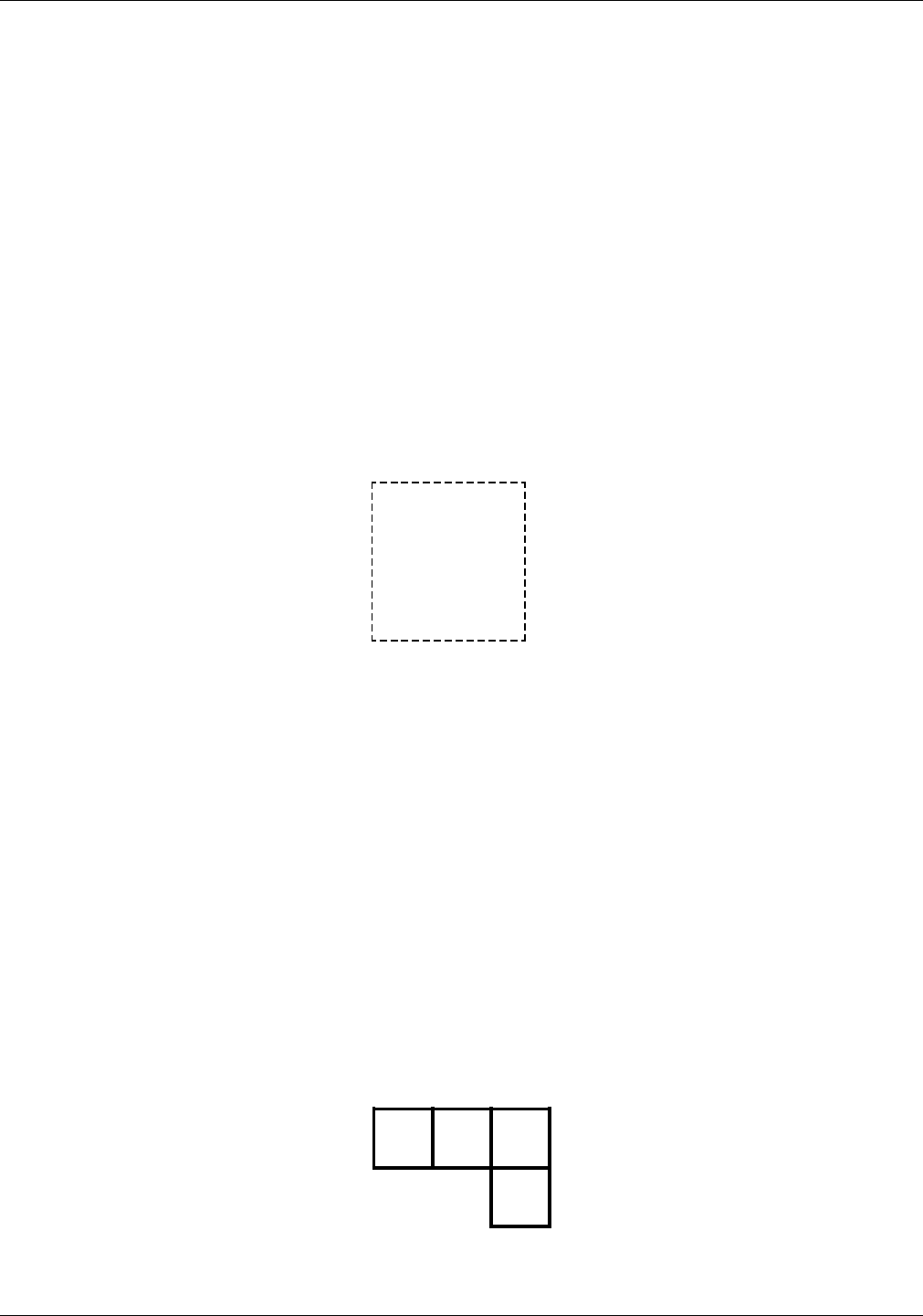
Adjacent boxes The BOX position is specified by the coordinates of the upper
left corner of the box in which the text string is to be placed. If
text is to be placed in an adjacent box (either vertically or
horizontally adjacent), this can be specified by an IN NEXT BOX
parameter, in the following format:
IN NEXT HORIZONTAL BOX ‘text’ ‘text’ ...;
Adjacent boxes must have a common side. The keywords IN
NEXT HORIZONTAL BOX specify the next horizontal box to the
right of the current box. The keywords IN NEXT VERTICAL BOX
specify the box beneath the current box. These adjacent boxes
are shown in figure 2-3. The default is HORIZONTAL.
Figure 2-3. Adjacent boxes
2-16 XEROX 4050/4090/4450/4650 LPS FORMS CREATION GUIDE
FORMS DESCRIPTION LANGUAGE
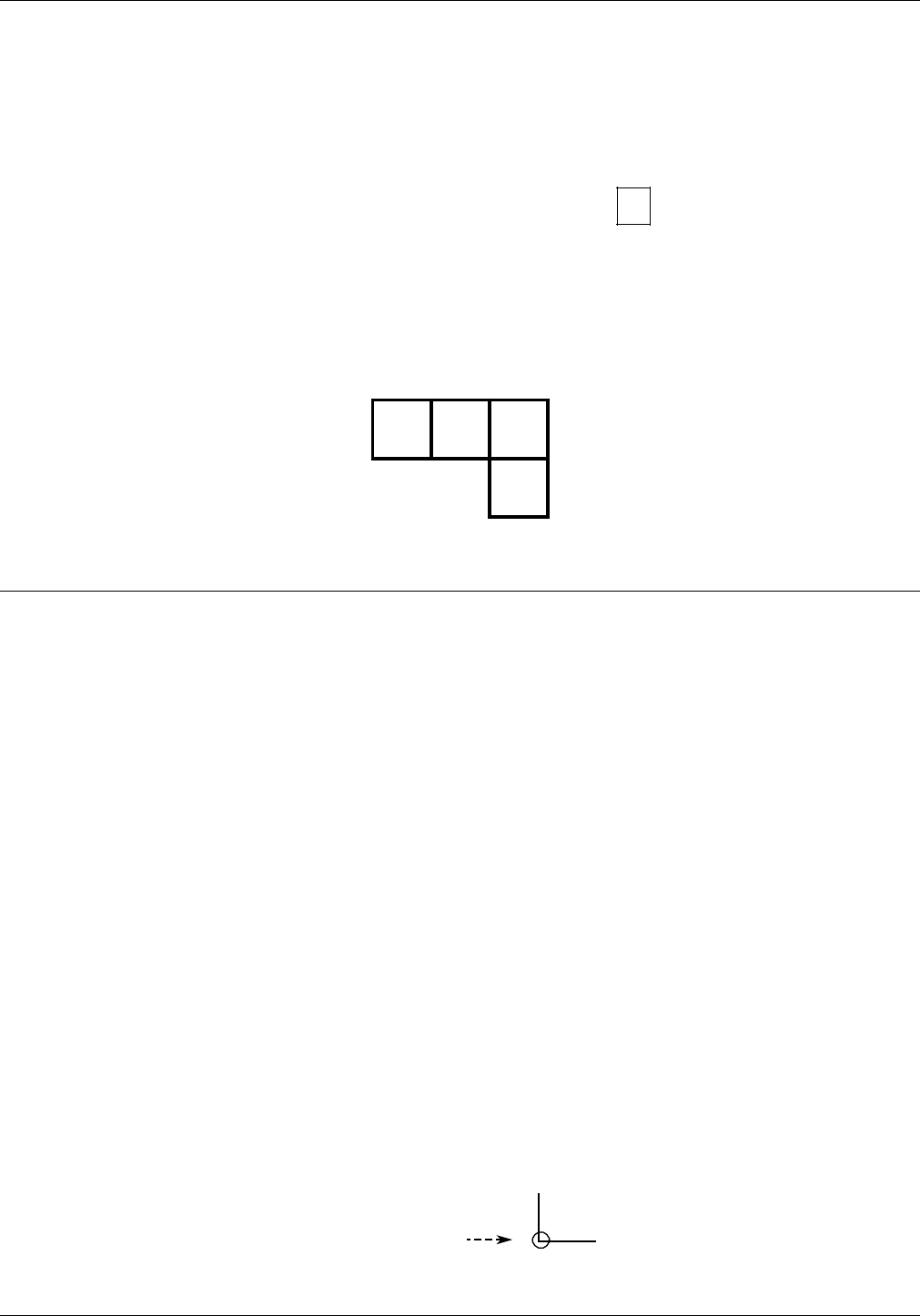
Assuming that the upper left corner of the first box above is
located two grid units down from the form origin and one grid
unit to the right of the form origin, you would use the following
statements:
TEXT IN BOX 2,1 ‘A‘
BOX ‘B‘
BOX ’C’
VERTICAL BOX ’D’;
TEXT IN BOX 2,1 ‘A:
IN NEXT BOX ‘B‘
IN NEXT BOX ’C’
IN NEXT VERTICAL BOX ’D’;
or
The results of either statement are shown in figure 2-4.
Figure 2-4. Placing text in adjacent boxes
D
CBA
LOGO
Use this command to place .LGO files. A complex figure called a
logo up to two square inches in size can be digitized to order by
the Xerox Font Center or Rank Xerox. This logo is a special font
of one or more characters, which carries with it the relative
position of the characters that make up the logo. Thus, while a
logo may be made up of many characters, it is positioned as a
single unit. For additional flexibility, a signature may be digitized
and stored on the system as a logo.
Syntax LOGO id AT y unit x unit;
Parameter options id The logo identifier (one to six characters).
y Coordinate on the y axis where the logo origin is to be
located.
unitUnit of linear measurement, expressed as inches (IN),
centimeters (CM), or DOTS. If units are not specified, the
measurement is in grid units.
x Coordinate on the x axis where the logo origin is to be
located.
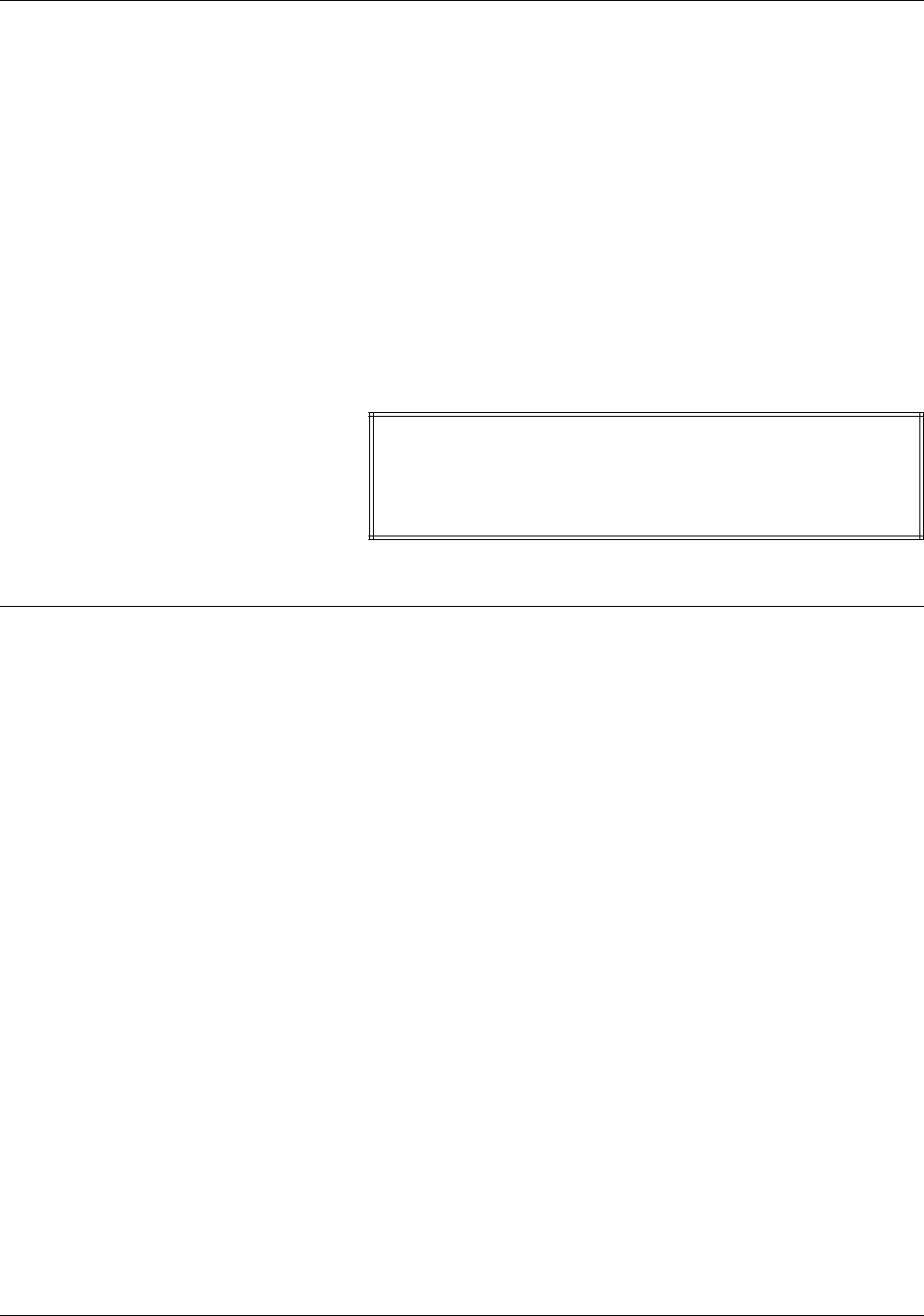
Example LOGO EAGLE AT 10,12;
Logo origin
XEROX 4050/4090/4450/4650 LPS FORMS CREATION GUIDE 2-17
FORMS DESCRIPTION LANGUAGE
LOGO
Keyword LOGO
EAGLE
The name of the logo, a one- to six-character alphanumeric
label, is given to the logo when it is digitized by the Xerox
Font Center or Rank Xerox.
AT 10,12
The keyword AT and the coordinates (y,x) indicating where
the logo is to be placed.
Considerations Be sure that font memory capacity is not exceeded. Logos larger
than two square inches may be used if they are the result of
using smaller components of the logo to gain the desired effect.
Sample .FSL The LOGO command is typically inserted near the end of the
.FSL, as illustrated in figure 2-5.
Figure 2-5. Placing a logo
HORIZONTAL TEXT USING FONT 2 IN CENTER CENTER
BOX 6,1 ’DATE’;
COMMENT *** PLACE LOGO ***;
LOGO EAGLE AT 1,26;
END;
GRAPHIC
You can use the GRAPHIC command to place your images at any
location on the page. A form may consist solely of graphics
(images). Each graphic to be associated with a form must be
specified in the .FSL file.
Syntax GRAPHIC name AT vpos unit hpos unit SCALE IS n/d;
Parameter options name
Name of a graphic (.IMG) file, found on the system disk.
vpos
Specifies the vertical position of the top edge of the graphic
relative to the virtual page origin. This parameter is a decimal
number with up to two decimal places (except for DOTS,
which must be an integer). If no unit is specified, grid unit
dimensions are used as the default.
unit Unit of linear measurement, expressed as inches (IN),
centimeters (CM), or DOTS. If units are not specified, grid
unit dimensions are used.
hpos
Specifies the horizontal position of the left edge of the
graphic, relative to the virtual page origin. The format of the
specification is the same as for vpos.
2-18 XEROX 4050/4090/4450/4650 LPS FORMS CREATION GUIDE

FORMS DESCRIPTION LANGUAGE
n/d Specifies the reference scale factor. Each parameter, n and
d, must be an integer in the range of 1 to 8 to allow a
reference scale factor in the range of 1/8 to 8. The reference
scale factor is multiplied by that specified at the time the
graphic was digitized, and the product is rounded to the
nearest integer in the range of 1 to 8. That integer becomes
the effective scale factor with which the graphic is imaged.
Default If no unit is specified, grid unit dimensions are used as the
default.
Example GRAPHIC AFJ AT 10, 12;
Sample .FSL A GRAPHIC command is illustrated in figure 2-6.
Figure 2-6. Placing a graphic
AT 31.6,31.6 DRAW BOX 46.8 WIDE BY 21.8 HIGH
USING SOLID 2;
AT 31.9, 31.9 DRAW BOX 46.2 WIDE BY 21.2 HIGH
USING SOLID 2;
AT 32.2,32.2 DRAW BOX 45.6 WIDE BY 20.6 HIGH
USING SOLID 2;
GRAPHIC UNICRN AT 31.5,42;
TEXT USING FONT 1 AT 83.5,2.5'FORM SM105';
Considerations Up to 16 images per page are permitted. The Raster Image
Processor (RIP), Interpress, and graphics capability (GVG2),
enable the printing of more than 16 images per page as well as
vector graphics.
SECTION
When a form consists of several identical sections, you can save
time by defining only one section and treating it as a module,
that is, having it repeated at desired locations.
Syntax BEGIN SECTION id;
or
DO SECTION id AT y unit x unit;
END SECTION;
Parameter options id An identifier (one to six characters) that is invoked when a
section is to be defined.
y Coordinate of the origin on the y axis of the section in
relation to the origin of the form.
unitUnit of linear measurement, expressed as inches (IN),
centimeters (CM), or DOTS. If units are not specified, the
measurement is in grid units.
XEROX 4050/4090/4450/4650 LPS FORMS CREATION GUIDE 2-19
FORMS DESCRIPTION LANGUAGE
x Coordinate of the origin on the x axis of the section in
relation to the origin of the form.
Default None.
Considerations SECTION can also be used to define an entire form as a section.
Within the section, any other command, statement, or
specification may be used except another SECTION command,
DO SECTION command, FORM command, or END command.
More than one section may be defined and invoked, but each
section must be terminated with the END SECTION command
before another section can be defined.
To invoke a section that has been defined, invoke the section
with the DO SECTION command. A section must be defined
before it can be invoked.
Example Figure 2-7 illustrates how the SECTION commands are invoked.
Figure 2-7. Specifying a section
FORM SEC 4;
PORTRAIT;
GRID FMT8;
FONT UN207B;
COMMENT *** CREATE PHONE MESSAGE PAD SECTION ***;
BEGIN SECTION PHONE;
AT 7 DRAW 7 HORIZONTAL LINES FROM 4 TO 33 USING SOLID 1 AND
REPEAT VERTICALLY AT 11,17,20,23,26,29;
HORIZONTAL TEXT USING FONT 1 AT 2,4 'PHONE MESSAGES';
HORIZONTAL TEXT USING FONT 1 AT 4,4 'CALLER:';
HORIZONTAL TEXT USING FONT 1 AT 8,4 'TIME:';
HORIZONTAL TEXT USING FONT 1 AT 12,4 'MESSAGE:';
END SECTION;
COMMENT *** PRINT MESSAGE PAD SECTION 4 TIMES ***;
DO SECTION PHONE AT 0,0;
DO SECTION PHONE AT 30,0;
DO SECTION PHONE AT 0,37;
DO SECTION PHONE AT 30,37;
END;
BEGIN SECTION PHONE;
BEGIN SECTION
Keywords
PHONE;
Name of the section. Rules for naming sections are identical
to those for naming forms: one to six alphanumeric
characters.
END SECTION;
Finishing command. Notice that the END SECTION
command does not use the section name. Including a
section name results in an error.
2-20 XEROX 4050/4090/4450/4650 LPS FORMS CREATION GUIDE

FORMS DESCRIPTION LANGUAGE
DO SECTION PHONE AT 0,0;
DO SECTION PHONE AT 30,37;
DO SECTION
Keywords.
PHONE
Section name. The section must previously have been
defined by the BEGIN SECTION and END SECTION
commands.
AT 0,0;
AT 30,37;
Coordinates of the origin of the section in relation to the
origin of the form.
COMMENT
It is often helpful to use comments to include in the source
statements a description of certain FDL commands and their
functions. These comments are useful when debugging your
program and can act as reminders if you or someone else
modifies the .FSL later. When you use comments, they appear
on the source statement only. They are not printed on your
form, and do not affect the execution of your program.
Syntax COMMENT text;
Parameter options text Text to be treated as a comment.
Default None.
Example This sample illustrates a COMMENT that identifies the procedure
that is to follow it:
COMMENT *** PLACE SECTIONS ***;
DO SECTION RSPNSE AT 0,0;
DO SECTION RSPNSE AT 7,0;
DO SECTION RSPNSE AT 14,0;
Comment nesting /* begins a comment and */ ends a comment.
/* THIS IS THE START OF A NESTED COMMENT
/* WHEN TWO ENDING COMBINATIONS ARE FOUND */
THE COMMENT IS TERMINATED */
A syntax error results if /* does not begin a comment and */
does not end a comment. Each comment beginning (/*) and
ending (*/) should be followed by at least one space character.
Considerations A semicolon must be inserted at the end of the comment text;
otherwise all of the following FDL commands are considered part
of the comment text and are not executed. The FDL compiler
ignores all comments up to the first encountered semicolon.
Asterisks or line spacing cause the COMMENT to stand out from
the text.
XEROX 4050/4090/4450/4650 LPS FORMS CREATION GUIDE 2-21

FORMS DESCRIPTION LANGUAGE
END
Use the END command to terminate the description of a form.
Syntax END;
Parameters None.
Default None.
Example An .FSL file can contain more than one file. Therefore, if
additional .FSL files follow an END command, the end of all .FSLs
to be processed is indicated by two consecutive END
commands. The command syntax is:
END;END;
2-22 XEROX 4050/4090/4450/4650 LPS FORMS CREATION GUIDE

3. Compiling and printing forms
Once the Form Source Library (.FSL) file has been created, the
file can be stored on the laser printing system (LPS) system disk.
The next step is to compile the file and print a copy of the form.
Form printing process
Follow these steps to print an electronic form on a Xerox laser
printing system:
1. Enter the editor utility and create a file of FDL commands to
describe the form. This file is called a Forms Source Library
(.FSL) file. Refer to the “Forms Description Language”
chapter for more information.
The .FSL file contains FDL commands such as coordinates for
placing lines, boxes, text, and so forth. You can create the
.FSL file directly at the LPS keyboard and display, at a host
computer input device, or through remote communications.
2. Save the .FSL file to the LPS system disk.
3. Compile the .FSL to create a printable electronic form file
(.FRM).
4. Debug, modify, and recompile the file if necessary.
5. Print the form.
.FSL data transfer
Once you have created the .FSL file, you can send it to the
system disk either offline or online.
Offline
In the offline mode, .FSL files can be transmitted to the system
disk from magnetic tape or by using the LPS Editor.
Using magnetic tape 1. Create the source file at the host computer and store it on a
magnetic tape.
2. Mount the tape on the LPS tape drive and copy the files
electronically to the system disk.
Using the LPS Editor The source code can also be entered directly to the LPS at the
system user interface and transmitted electronically to the system
disk.
XEROX 4050/4090/4450/4650 LPS FORMS CREATION GUIDE 3-1

COMPILING AND PRINTING FORMS
Online
If your LPS is channel-attached to a host computer, enter the
source code at the host terminal through the host editor facility.
The file must be preceded by the necessary control record
identifiers. Refer to your host reference documentation for
details. The LPS HOSTCOPY utility enables you to download files
from the host and store them on the LPS system disk.
Remote communications The LPS can also receive forms data from a remote device on the
Ethernet network.
Compiling a form
Once the file has been created, the next step is to enter the
command that compiles the .FSL to an .FRM.
Multiple .FSLs contained in one file are paginated so that each
new .FSL starts on the front side of a new page.
FDL compilation time
The time it takes to compile a form file depends on the position
of the font file in its directory and the size and number of disks
on the system. If your LPS has a large number of font files
located on several disks, you may notice an increase in
compilation time for forms that perform text handling. To ensure
that your form files compile as quickly as possible, remove any
unnecessary font files and use the COMPRESS utility to
reorganize your files on the disk. This will shorten the font
lookup time and use the disk space efficiently.
Invoking the forms compiler
To invoke the forms compiler, enter the following command at
the LPS keyboard. The entire command must fit on one line.
FDL filename NOPRINT TRAY DEBUG XPAN NOSOURCE PROOF SIMPLEX RES=spi
The FDL compilation command includes any combination of the
following options.
Parameter options filename
Specifies the name of the .FSL to be compiled. The file
extension, .FSL, may be included. No other extension is
allowed. The file name cannot be a keyword option such as
TRAY, DEBUG, XPAN, and so on. These are reserved names
that could cause problems when you use a task outside of
the forms compiler.
NOPRINT
Specifies that the .FSL source statements listing, form
summary, and sample form will not be printed. However, if
an error occurs during form processing, the listing and the
summary are printed.
3-2 XEROX 4050/4090/4450/4650 LPS FORMS CREATION GUIDE

COMPILING AND PRINTING FORMS
TRAY
Specifies that the sample form, source statement, and
summary sheet will go to the sample tray instead of the
currently active output stacker.
DEBUG
Specifies that no attempt to print the sample form will be
made. This ensures that the source statement and summary
sheet are printed even if the sample form cannot be printed.
XPAN
Specifies printing of the source statement of section
expansions.
NOSOURCE
Specifies that disk source file creation will be suppressed
when compiling from magnetic tape or disk when the form
name is the same as the file name given.
PROOF
Specifies that the .FSL will be compiled and the source
statement and/or summary sheet will be printed. No .FRM
file is generated.
SIMPLEX
Specifies that the source statement or summary sheet
generated with each compile is printed in simplex rather than
duplex.
RES=spi
Specifies a 300 or 600 spots per inch (spi) resolution.
If the source file contains multiple form descriptions, the system
does not start printing until all forms have been compiled.
Compiling 600 spi forms A 600 spots per inch (spi) form can be compiled only on a 4650.
It is important, however, that all 600 spi system fonts, logos, and
image files are loaded on that system prior to compilation.
Compiling 4850 color forms and logos V3.5 operating system software does not support any color
references. Color forms created on a 4850 LPS using the
IRESULT, ICATALOG, and PALETTE commands are accepted and
can be printed successfully on the 4050, 4090, or 4650 LPS;
however, problems occur when calling out color format LGOs
and IMGs. A form or logo that was created and compiled on a
4850 can be printed (in monochrome black) only on a 4050,
4090, or 4650 LPS using V3.8 (or higher) operating system
software releases.
When an .FSL is compiled and the name of the source input file
differs from the name in the FORM command, an .FSL is created
using the name from the FORM command. This newly created
.FSL contains only those commands necessary for that form.
However, if the input file has the same name as the one in the
FORM command, the original .FSL file is not affected.
If there are multiple forms in the input source and the source
input file name is used for any of the forms other than the first,
an error occurs during compilation. Therefore, if you wish to use
the source input file name as one of the form names, you must
use it as the first form to be compiled. Typically, forms
contained in a multiple-file .FSL do not have the same name as
the source input file. An example of this is DC20.FSL.
XEROX 4050/4090/4450/4650 LPS FORMS CREATION GUIDE 3-3

COMPILING AND PRINTING FORMS
If an .FSL with multiple forms has one form name which has the
same name as another .FSL, this second .FSL will be overwritten
when the first is compiled. For example, assume that file A.FSL
contains forms X, Y, and Z. When it is compiled, files X.FRM,
Y.FRM, and Z.FRM are produced, as are files X.FSL, Y.FSL, and
Z.FSL. If there already is a file name X.FSL on the system, it is
overwritten by X.FSL from the A.FSL file.
Summary sheet
If the compilation is successful, a summary sheet of statistics is
printed with the following:
• Size of the source output file
• Size of the printable form file
• Size of the form image buffer
• Total amount of font memory used.
The summary sheet is printed duplex by default. If you want it
printed simplex, include the SIMPLEX option in the task
invocation line as follows:
FDL TRYIT SIMPLEX
Multiple .FSLs contained in one file are paginated so that each
new .FSL starts on the front side of a new page.
Error checks
If the compilation fails, a list of error messages is printed. If a
command extends over several lines, an error message may not
appear on the next consecutive line following the error. This
may result in two consecutive error messages at the end of a
command. An example of this is the CANNOT FIND THE BOX
message that may occur for a TEXT IN BOX command.
As the .FSL file is processed, it is automatically checked for the
following errors.
• Unknown, illegal, or missing commands, keywords, or
parameters
• Requests for items to be placed or drawn outside of box or
page boundaries
• Invalid font or logo requests
• Illegal grid units or syntax.
Errors are flagged in the source statement with messages
specifying the type of error. Refer to the Xerox LPS Message
Guide for a description of error messages that may appear while
forms are being compiled.
Using the compilation options
After communicating the .FSL to the LPS disk, you compile,
debug, and modify (if necessary) the .FSL using the following
options.
3-4 XEROX 4050/4090/4450/4650 LPS FORMS CREATION GUIDE

COMPILING AND PRINTING FORMS
File storage
A large number of forms may be stored in the forms source
directory (uncompiled) and form directory (compiled) on the
system disks. Two files with the same name cannot be stored in
the same directory. The number of forms that can be stored
depends on the amount of data required to describe each form
and the total amount of disk space allocated to the libraries.
The forms are filed in the system under their identifying names.
The information stored in the file includes the identifier, the
encoded form, and the list of specified fonts and logos. The
original source statements that created the forms description are
stored separately under the same identifier.
A list of all of the forms stored in the directory, a sample of each,
and the source statement lists can all be obtained using operator
commands.
PROOF
The forms compiler makes it possible to compile a form and
delete the .FRM file after it has been printed. If you use this
option, less disk space is consumed by resident form files. The
PROOF option has the following format:
FDL filename PROOF
If the form is compiled without errors, the .FRM file and the
source statement and/or summary sheet is printed. Since the
PROOF option deletes it, there is no form file on the disk.
When you use the PROOF option, the form file that is created is
given a pseudonym that differs from the one specified in the
.FSL. Therefore, when TRYIT.FSL is compiled, for example, the
form that is created is not automatically named TRYIT.FRM. The
newly created .FRM file is given a different name, and it is this
renamed form that is eventually deleted. Due to this safeguard,
if a file named TRYIT.FRM already exists on the system disk, that
form still exists after the new .FRM file is compiled and deleted.
Secured files
• If you attempt to overwrite a secured file while compiling a
form, a security violation message displays, and the
compilation process is aborted.
• If you attempt to overwrite a secured file having the same
name on both the task invocation line and in the .FSL, a
security violation message is displayed and the form is
aborted.
For example, TRYIT1.FSL is a secured file.
You enter: FDL TRYIT1 TRAY
The .FSL contains: FORM TRYIT1;
GRID IS 1 INCH;
END;END;
In this case, a security violation message displays and
compilation aborts.
XEROX 4050/4090/4450/4650 LPS FORMS CREATION GUIDE 3-5

COMPILING AND PRINTING FORMS
• If the form names on the invocation line and in the .FSL are
different, the compilation is aborted and a single sheet is
printed. The sheet contains the heading for the page and
the portion of the .FSL that was processed before the
security violation was detected.
For example, TRYIT1.FSL is a secured file.
You enter: FDL TRYIT TRAY
The .FSL contains: FORM TRYIT1;
GRID IS 1 INCH;
END;END;
In this case, a security violation message still displays and the
compilation aborts, but a single page is printed containing
the page heading and the .FSL line “FORM TRYIT1;”.
Example 1 FDL TRYIT TRAY
This command compiles the .FSL named “TRYIT” (provided it
does not contain errors), generates the source statement, prints
a copy of the statement and the form, and delivers both to the
SAMPLE tray.
If you do not include the word TRAY in your command, the
printout is delivered to the currently active bin.
Example 2 If you want to compile the form, but you do not want a printout
of the form just yet, enter the following:
FDL TRYIT NOPRINT
The .FSL compiles, but the form and the source statement do not
print.
Printing a compiled form
Once a form has been compiled, the object code is stored on
the system as an .FRM file. To print copies of the form, enter the
SAMPLE command at the LPS keyboard. The format of the
SAMPLE command is:
SAMPLE filename.FRM
For example, to produce five copies of the form, enter the
following:
SAMPLE TRYIT.FRM 5
When an FRM is compiled using FDL software version 2 (or later),
the paper size is defined by the PAPER SIZE IS XX BY YY
statement in the .FSL. If the paper size is not defined, the paper
size defaults to the sysgened paper size. FRMs compiled prior to
version 2 (before the paper size statement of FDL was
implemented) use the sysgened paper size. If there are graphics
in the form, FDL does not guarantee that the image fits on the
page. If necessary, the following message appears:
OS6191 GRAPHIC xxxxxx OFF PAGE AND WILL NOT BE PRINTED
3-6 XEROX 4050/4090/4450/4650 LPS FORMS CREATION GUIDE

4. Troubleshooting
Physical printer constraints and forms compiler methods are
factors that can affect form design. This chapter provides coding
technique suggestions and hints and tips to help you avoid
coding problems. This chapter also covers factors that may
impact the following:
• Image complexity
• Boxes
• Shading
• Sections
• Rounding measurements.
Suggested coding techniques
Converting preprinted forms
Follow these steps to convert preprinted forms:
1. Print data, using an appropriate format, on the laser printing
system.
2. Draw horizontal and vertical lines on the system output.
3. Use the forms design ruler to measure line and character
spacings. Refer to the “Support tools and measurements”
appendix.
4. Code the form.
Designing new forms
Follow these steps to design new forms:
1. Determine the appropriate format.
2. Use the forms design ruler to measure line and character
spacings. Refer to the “Support tools and measurements”
appendix.
3. Draw horizontal and vertical lines on a layout sheet. Use
standard layout sheet forms FLSF1 through FLSF11 that are
provided in the FDL software. Layout sheet forms and
corresponding paper sizes are shown in table 4-1.
4. Define the x and y coordinates.
5. Code the form.
XEROX 4050/4090/4450/4650 LPS FORMS CREATION GUIDE 4-1

TROUBLESHOOTING
Table 4-1. Layout sheet forms and paper sizes
Layout sheet
forms Paper size
FLSF1 through
FLSF11 8.5 x 11 inch/
216 x 279 mm
FLSF1A and
FLSF11A A4
FLSF12 and
FLSF13 8.5 x 14 inch/
216 x 356 mm
Recommended coding sequence
The FDL compiler imposes a number of constraints on the
sequence in which commands are coded. The form name must
come first. Only one form orientation is permitted, and fonts
and boxes must be implicitly or explicitly defined before they are
referenced by TEXT commands. After that point, the sequence is
not significant to the compiler. However, it is worthwhile to
develop a sequence while debugging or making changes to a
form. Use a method of sequencing commands similar to the
following:
• Horizontal and vertical lines
• Boxes (if needed)
• Text
• Logo placement
• Shading.
Syntax ambiguities
Because FDL keywords can be abbreviated to the first three
characters, and because certain two-character keywords can be
interpreted in more than one way, the following known
ambiguities exist:
• IN (preposition) is interpreted as IN (inch). For example:
TEXT 1 IN BOX...;
Also,
TEXT SPACED 1 IN BOX...;
The keyword IN is interpreted as INCH, while the required
keyword IN (preposition) is detected as missing and an error
message results. The solution to this situation is to write the
following:
TEXT 1 IN IN BOX...; or
TEXT 1 INCH IN BOX...; or
TEXT 1 DOTS IN BOX...;
• FMTn cannot be abbreviated.
4-2 XEROX 4050/4090/4450/4650 LPS FORMS CREATION GUIDE
TROUBLESHOOTING
• [DOT\TED is interpreted as [DOT\S. For example:
AT 18 DRAW 5 HORIZONTAL LINES FROM 27.5 TO 37.5 DOT...;
The keyword DOT is interpreted as DOTS, which is valid in
this position. The keyword DOTTED is also valid in this
position, but must be spelled out in full.
• [CEN\TER is interpreted as [CEN\TIMETERS. For example:
TEXT 10 CEN IN BOX.....;
The keyword CEN is interpreted as CENTIMETERS, which is
valid in this position. The keyword CENTER is also valid in
this position but must be spelled out in full.
Hints and tips
You can avoid coding problems by using the coding technique
suggestions, hints, and tips shown in table 4-2.
Table 4-2. Hints and tips
Keywords Hints and tips
Form id • Develop a logical, systematic approach to naming conventions.
• Take care not to choose a previously used form id.
GRID command Choose a format that is compatible with the data.
Coding lines • Use a COMMENT command.
• Code all horizontal lines, then all vertical lines. Precede each set with a comment
statement.
• Code longer lines first. Then follow with the shorter segments that may overlay the
basic long lines.
• Code lighter lines first. Then code shorter segments that are heavier in density.
• Code a SOLID 0 line first whenever you have a set of colinear segments, whether
they are touching or not.
• Use lines rather than characters of the form element font, whenever possible.
• Avoid overlapping (superimposing) lines.
• Avoid using too many dotted or broken lines because they create too much
overhead in the printing process.
• Avoid drawing unneeded lines across the longest side of the physical page.
Coding boxes • Use a COMMENT command.
• Use a BOX command only when the lines generated by that command are not
duplicated by another command.
• Do not use a REPEAT command when drawing lines that create boxes if you need to
find the coordinates of those boxes later.
• Use boxes rather than characters of the form element font, whenever possible.
• Avoid overlapping (superimposing) boxes.
Use of shading • Use a COMMENT command.
• Avoid overlapping the boundary line of a box with shading. Set shading back from
borders by three to five dots (or about 0.1 units for most coordinates). This
conserves memory and results in a cleaner appearance.
• Try to avoid shading on portrait forms.
XEROX 4050/4090/4450/4650 LPS FORMS CREATION GUIDE 4-3
TROUBLESHOOTING
Table 4-2. Hints and tips (continued)
Keywords Hints and tips
Coding text • Use a COMMENT command. Remember that different fonts of a given point size are
not necessarily the same physical size.
• Be aware that vertical error messages, generated when the system calculates that too
much text has been specified for placement in a box, are an approximation.
• Use the TEXT SPACED AT command to force exact text placement.
• Avoid placing too many small characters in one area of the page.
• Avoid overlapping characters to achieve bolding or other effects. Use the correct
font whenever possible.
• Avoid too many font switches on the same text line. This creates overhead in the
printing process.
Coding sections • Use a COMMENT command.
• Use coordinates based at 0,0 when defining a section. Then place the section at the
locations you want.
Source copy If the source filename (.FSL) and the form name (the name that follows the FORM
keyword) do not agree, an .FSL file is created that has the same name as the form name.
Therefore, when you copy X.FSL to Y.FSL and compile Y.FSL without changing the form
name in Y.FSL, the original X.FSL is deleted and a new X.FSL is created from the Y.FSL
source. Furthermore, the form file (.FRM) that is created is X.FRM and not Y.FRM. If you
wish to create a distinct source using another .FSL as a base, you need to change the
form name to the same name as the source name, or to some other name that does not
already exist. Two files with the same name and type cannot reside on the system.
Image complexity factors
Form design is limited by physical restrictions on the amount of
image data (characters and lines) that can be printed on a scan
line and on a page.
Line tables
Forms Description Language (FDL) line tables are internal FDL
data structures that provide a record in memory of the lines to
be drawn on a page. These tables allow the system to find the
corners and edges of boxes when they are referenced later.
Since excessive amounts of memory would be required to store
every line, the FDL compiler retains only the memory of the
longest lines that pass through any given coordinate in a
particular direction. FDL replaces dotted or broken lines with an
invisible line of the same length.
Line table limits The FDL line tables can store 1,999 vertical and 1,999 horizontal
lines in memory. When you exceed either of these line table
limits, the following message is displayed:
TOO MANY HORIZONTAL OR TOO MANY VERTICAL LINES
This message warns you that the new user-specified line cannot
be retained in the table. The message is of no real consequence
to you unless the new line is intended as the side of a box. In
that case, the box is not found and your form may not compile.
4-4 XEROX 4050/4090/4450/4650 LPS FORMS CREATION GUIDE

TROUBLESHOOTING
Generally, the line table limits are reached because the form
contains a large number of short line segments. The most
probable reason for this is a series of vertical lines (for example,
tick marks) or horizontal lines (for example, a series of long
dashes). With either of these conditions, it is possible to reduce
the number of entries in the line table as the form is being
constructed.
Importance of orderly construction
One consideration in determining the orderliness of form
construction is that the algorithm used in loading the line table is
designed to check only the following two criteria before entering
a new line in the line table:
• Is the new line contained within the boundaries of an
existing line?
• Is the new line an extension of one of the existing lines?
If the new line is contained within the boundaries of an existing
line, no change is made to the line table entries. If the new line
is an extension of one of the existing lines, the boundaries of the
first (and only the first) existing line are extended to include the
new line. If neither of the criteria is met, a new entry is made in
the line table.
Examples The procedure of line extension results in an irregularity if lines
are not specified in an orderly manner. For example, draw five
line segments that are each five units in length. If the lines are
drawn in an unreasonable or irregular manner, as shown below,
the result is more entries in the line table than are necessary.
Drawing line segments in the order 0 to 5, 10 to 15, 20 to 25, 5
to 10, and 15 to 20 creates a single visual line that FDL considers
to be three lines. This is because the criterion of the line table
allows the extension of only the first line segment with common
coordinates to the new line. In this case, the three line entries in
the line table would be 0 to 10, 10 to 20, and 20 to 25. Figure
4-1 shows examples of extraneous drawn lines.
Figure 4-1. Example of extraneous drawn lines
It is also possible to have the line table show more than one line
passing in the same direction through a given coordinate. For
example, draw three lines, each of which is five units in length (0
to 5, 10 to 15, and 20 to 25). Then draw two lines, each of
which is nine units in length (3 to 12 and 13 to 22). The result is
a single visual line for which FDL has three entries in the line
table (0 to 12, 10 to 22, and 20 to 25). Figure 4-2 shows lines
entered in unintended locations.
XEROX 4050/4090/4450/4650 LPS FORMS CREATION GUIDE 4-5

TROUBLESHOOTING
Figure 4-2. Lines entered in unintended locations
These two examples of lines entered in the line table result in
lines that are visually contiguous but are not logically contiguous.
As indicated in the following sections that describe problems
with boxes, such conditions can result in a situation where FDL
cannot find a box, or creates a box that has one or both of its
dimensions equal to zero.
Suggested techniques for entering lines To enter lines, draw the longest possible logical line first, then
draw any shorter elements. If the logical line consists of different
types of lines (for example, solid and dotted), draw a SOLID 0
line first, extending over the full range of the logical line. For
example, the above example of five line segments of five units
each might have consisted of alternating solid and dotted lines.
In that case, the following is the most reasonable method of
specifying the total line:
AT 0 LINE 0 TO 25 USING SOLID 0;
AT 0 LINE 0 TO 5 USING SOLID 2 AND AT 10, 20;
AT 0 LINE 5 TO 10 USING DOTTED 1 AND AT 15;
Figure 4-3 shows the resulting line.
Figure 4-3. Line made up of different types of lines
Scan line density
Scan line density depends on printer and imaging speed.
Therefore, it can vary with each product and even with different
configurations of the same product. The basic limitation is linked
to dispatchable items, which become visible in character count
and number of lines.
Line density errors Both characters and lines contribute to the dispatchable item
count. When one dispatchable item is superimposed over
another dispatchable item, the result is considered to be two
dispatchable items by the system. When too many dispatchable
items are present on a scan line on the long axis of the paper,
the LPS operating system displays the following line density error
message:
OS6950 LINE DENSITY EXCEEDED
4-6 XEROX 4050/4090/4450/4650 LPS FORMS CREATION GUIDE

TROUBLESHOOTING
The hardware limitation of 320 dispatchable items per 300 spi
scan line (640 for 600 spi) includes the required overhead of two
dispatchable items. For example, a dispatchable item could be a
maximum of 32 dots wide for 300 spi (64 dots for 600 spi), and
thereby might be a full character (less than point size 8 or 9), a
fraction of a character (greater than point size 8 or 9), or a line
segment that is equal to or smaller than 32 dots in the scan
direction.
Determining line density limitations The following is a guide for determining 300 spi line density
limitations. If printing at 600 spi, the same size character or same
length line has twice as many dots, as follows:
• Every 32 dots (or fraction thereof) of a line drawn on the
long axis of the paper are one dispatchable item.
• Each line drawn on the short axis of the paper is one
dispatchable item.
• Each active character is at least one dispatchable item. (An
active character includes all the space from the top of the
character cell to the bottom of the character cell, even if
there is only white space present on a given scan line.) If the
dimension along the scan line is greater than 32 dots, the
character consists of some multiple dispatchable items.
It is not possible to construct a form with two adjacent lines if
both use the full count of 318 dispatchable items (320 minus the
two required for overhead) resulting from text and lines. The
imaging system requires a rest period of about four scan lines
before it can image the second fully loaded line.
Landscape pages Line density restrictions differ as a function of the mode
(landscape or portrait) of the form. An 8-point or smaller
landscape font is smaller than 32 dots for 300 spi and 64 for 600
spi. A vertical line is a single dispatchable item. A horizontal line
is treated as a series of 32 dots in length, joined end-to-end.
For 300 spi, this means that a form using an 8-point or smaller
font on a landscape page may have up to 318 characters (plus a
two-item overhead, for a total of 320 dispatchable items) on a
scan line. For example, when using a 6-point font, it is possible
to have 132 characters, a line across the page under the text, and
up to 90 vertical lines, without exceeding the line density
limitations.
If a form requires a 9-point or larger font, the number of
characters that may be imaged on a landscape page is reduced to
160 because the characters are generally more than 32 dots
wide. While the dispatchable-item count remains 320 per line,
fonts 9 points and larger use two dispatchable items per
character. Since a character in a large font constitutes two
dispatchable items, only half as many characters in a large font
may be imaged on a scan line as is possible with a smaller font.
Portrait pages Restrictions for a portrait page are significantly different from
those for a landscape page because the system always images in
the landscape direction. Therefore, if a page is formatted in
portrait orientation, the hardware must reorganize the data into
landscape prior to imaging.
XEROX 4050/4090/4450/4650 LPS FORMS CREATION GUIDE 4-7

TROUBLESHOOTING
On a 300 spi portrait page, a 12-point font drops the
dispatchable-item count below the 320-character level. A form
with a 12-point font cannot have more than 160 characters on a
scan line.
When using an 8-point 300 spi font on a portrait page, the
maximum dispatchable item count is approximately 200 per scan
line. This limit falls off to 170 characters for a 6-point font, 150
characters for a 5-point font, and 120 characters for a 4-point
font. (If printing at 600 spi, the same size character or length
line has twice as many dots.)
Superimposed lines
Since lines superimposed over each other count as double the
dispatchable items of a single line, they detract from the system
capabilities. If printing at 600 spi, you see the following
message:
EXCEEDED LINE DENSITY.
Page generation errors
Generally, a form is imaged along with variable data. It is
possible to create a form that prints correctly when sampled but
cannot successfully be overlaid on certain variable data pages.
The LPS may not have enough time to merge a complex form
with a large amount of variable data within the limits of the
throughput environment. In this case, either reduce the amount
of variable data, or simplify the form.
Review the broken page to determine the approximate location
of the failure, and try to reduce the number of characters and
lines in that area. Most imaging problems are local density of
information problems rather than page-wide problems.
Local density and page setup errors
One problem that may occur while a page is being imaged is a
page setup error, displaying the following message:
OS9300 PAGE SET-UP ERROR
This message means that there was not enough time to image a
page. This may be caused by an excessively large amount of
data and forms to be imaged, disk errors, image generation
problems, or a problem known as local density.
Even a form designed to avoid exceeding line density limitations
may cause page setup errors because of local density. However,
such problems are rarely encountered in readable forms. To
have a problem area of local density, a form would have to have
long lines of very closely spaced small text.
A local density problem occurs when the imaging hardware
accepts and dispatches characters at two different rates. If a
form structure imposes a dispatching load that is too heavy, the
hardware may run out of input before the data processing is
finished.
4-8 XEROX 4050/4090/4450/4650 LPS FORMS CREATION GUIDE
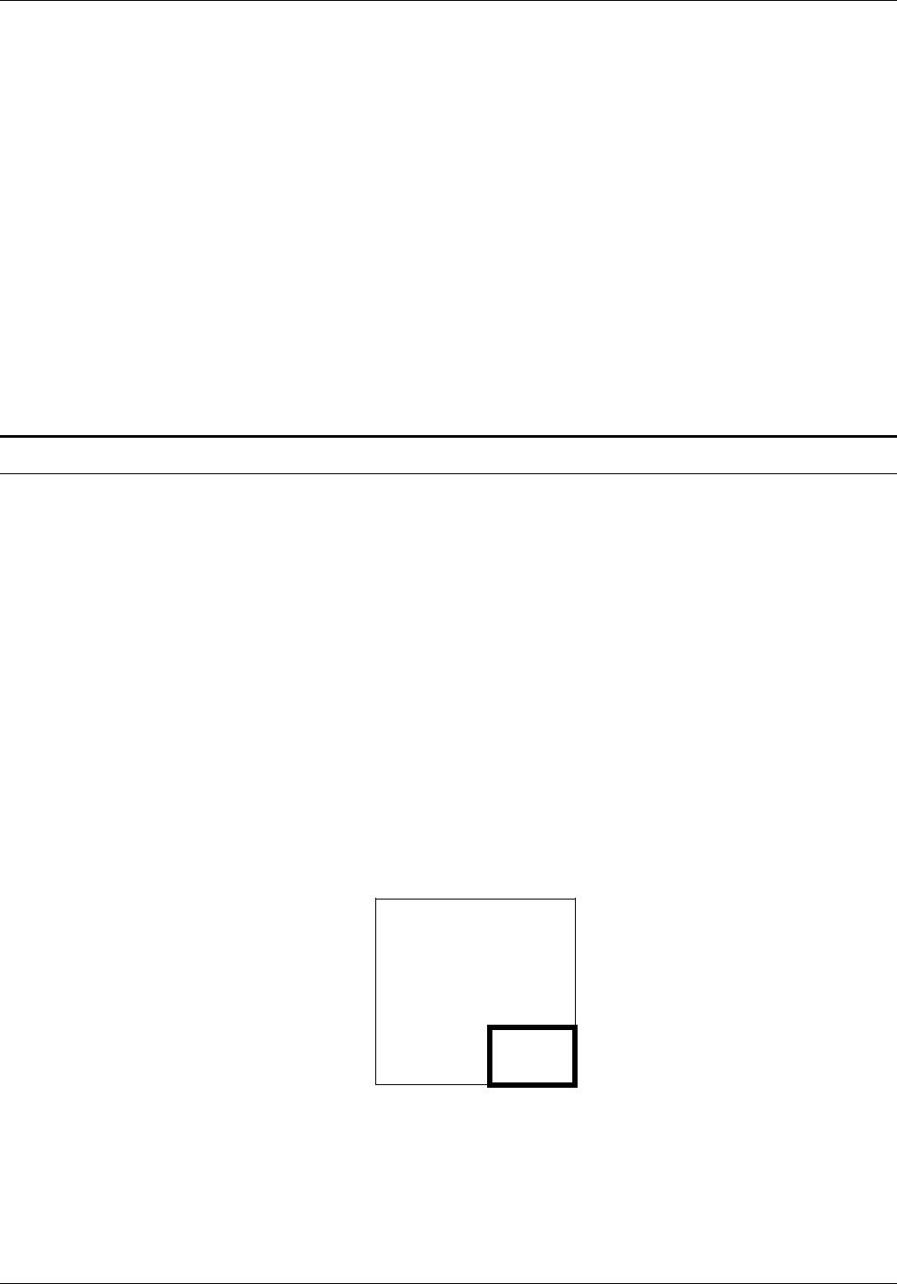
TROUBLESHOOTING
Considerations If a form you described causes page setup errors, examine the
form and variable data to see if there are many lines or a large
amount of text in a small area. If there are, you can reduce the
density of this area by spreading out the material or by deleting
parts of the form.
To determine possible causes of page setup errors due to local
density, look for the following items:
• Large amounts of closely spaced text in a small font; that is,
long lines of solid text with minimum spacing, especially if a
form is portrait.
• Large amounts of text in an orientation different from the
defined form orientation; for example, portrait text in a
landscape form.
• A large number of lines drawn on the short axis of the paper;
that is, vertical lines on a landscape form.
Using boxes
You can draw boxes with a single BOX command or construct
them with commands on a line-by-line basis.
A line density problem can occur if a single BOX command is
used to specify a box that is adjoined to another box by a single
side. When two BOX commands are issued in this manner, one
line of a box is superimposed over another along the adjoined
side. Since two lines are drawn between the same pair of
coordinates, a line density problem may occur.
When to use the BOX command To avoid this situation, use the BOX command only for the
following conditions when designing a form:
• The box is fully isolated from any other lines.
• The line type of a box is different from any other lines that
share its boundaries, for example a SOLID 2 box sharing a
small portion of a SOLID 1 edge, as shown in figure 4-4.
Figure 4-4. SOLID 2 box sharing part of a SOLID 1 box edge
XEROX 4050/4090/4450/4650 LPS FORMS CREATION GUIDE 4-9

TROUBLESHOOTING
Text in boxes
When text is entered for placement within a box, the system
attempts to determine whether the given text exceeds the largest
font size that can fit within the boundaries of the box. If FDL
computations indicate that the entered text may not fit within the
box, the following error message is displayed:
TEXT WILL NOT FIT IN THE BOX
The system checks the horizontal and vertical directions of the
box. If an error is detected in one or both directions, an attempt
is made to indicate an approximate value for the largest font.
Locating the closest box
When you specify text to be placed in a box, the system locates
the closest box within a ten-dot square of the specified point.
Example If text is to be placed in a box located two grid units by two grid
units from the origin of the form, the system selects the box
closest to this point and within ten dots square. The upper left
corner of this box becomes the relative origin for subsequent
text placement.
• If text is to be placed in the next box horizontally, FDL
begins searching at the upper right corner of the box in
which previous text was placed.
• If text is to be placed in the next box vertically, the search
begins at the lower left corner.
Error calculations
Horizontal errors The calculations made for horizontal errors (for example, too
many characters in a line) are usually accurate. FDL uses the
following formula for reporting horizontal errors:
S = P * (B/T)
S target point size
P original font point size
B width of the box in dots
T width of the text in dots.
Vertical errors The calculation made by FDL for vertical errors (for example too
many lines in the box) is a rough approximation of the actual size
of text, and the computation may, in fact, be larger than the font
for which an error message was displayed. This is because the
FDL calculation does not take into account the leading used
within the font or provided by line spacing specifications.
The following formula is used by the error-handling routine to
compute text size when the box is too small in a vertical
direction:
S = (72/300) * (D/N)
S target point size
72 number of points in an inch
300 number of dots in an inch
D distance between top and bottom of the box (in dots)
N number of lines that are involved.
4-10 XEROX 4050/4090/4450/4650 LPS FORMS CREATION GUIDE
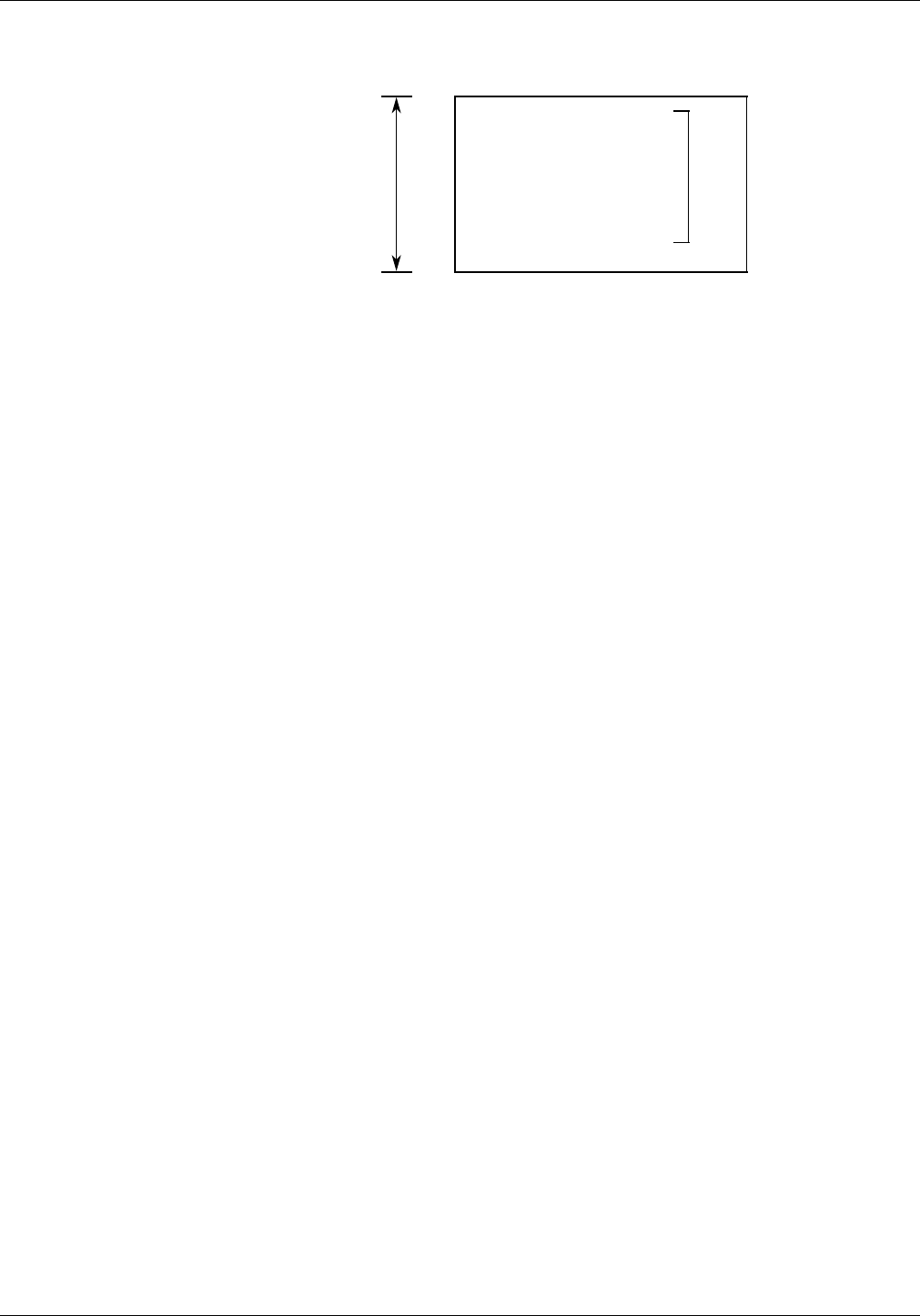
TROUBLESHOOTING
Figure 4-5. Measurements used in computing vertical box
TEXT IN LINE 1
TEXT IN LINE 2
TEXT IN LINE 3
D N
The result of this equation is rounded up and displayed in the
error message. Thus, what the error message actually signifies is
the largest font that could be accommodated within the box if
no leading were involved.
Correcting text-in-box errors If an error is detected, you have the following choices:
• Make the box larger
• Reduce the number of lines
• Use a smaller font
• If text fits visually, use a TEXT AT command rather than a TEXT
IN BOX command.
Centering text in boxes FDL uses line spacing as the vertical unit of size in centering text
within a box. In a small box, text that may not appear to be
properly centered may actually be centered accurately if line
spacing is considered. FDL cannot evaluate the aesthetics of the
final printed product. Therefore, it is up to you to create an
appropriate appearance for centered text.
Specifying line spacing within boxes Most often, it is easiest to allow FDL to position text within
boxes. In cases where the result is not satisfactory, you can do
the following:
• Specify an overriding line spacing value.
• Exercise more control over text placement and assure
satisfying aesthetic requirements with the SPACED AT option,
possibly used with blank lines, or the TEXT AT command (that
is, specifically positioning text).
• If overriding the line spacing does not achieve a satisfactory
appearance in a form, specify a line spacing that is smaller
than the natural spacing of the font. A line spacing smaller
than the height of the characters can be used with blank
lines.
XEROX 4050/4090/4450/4650 LPS FORMS CREATION GUIDE 4-11
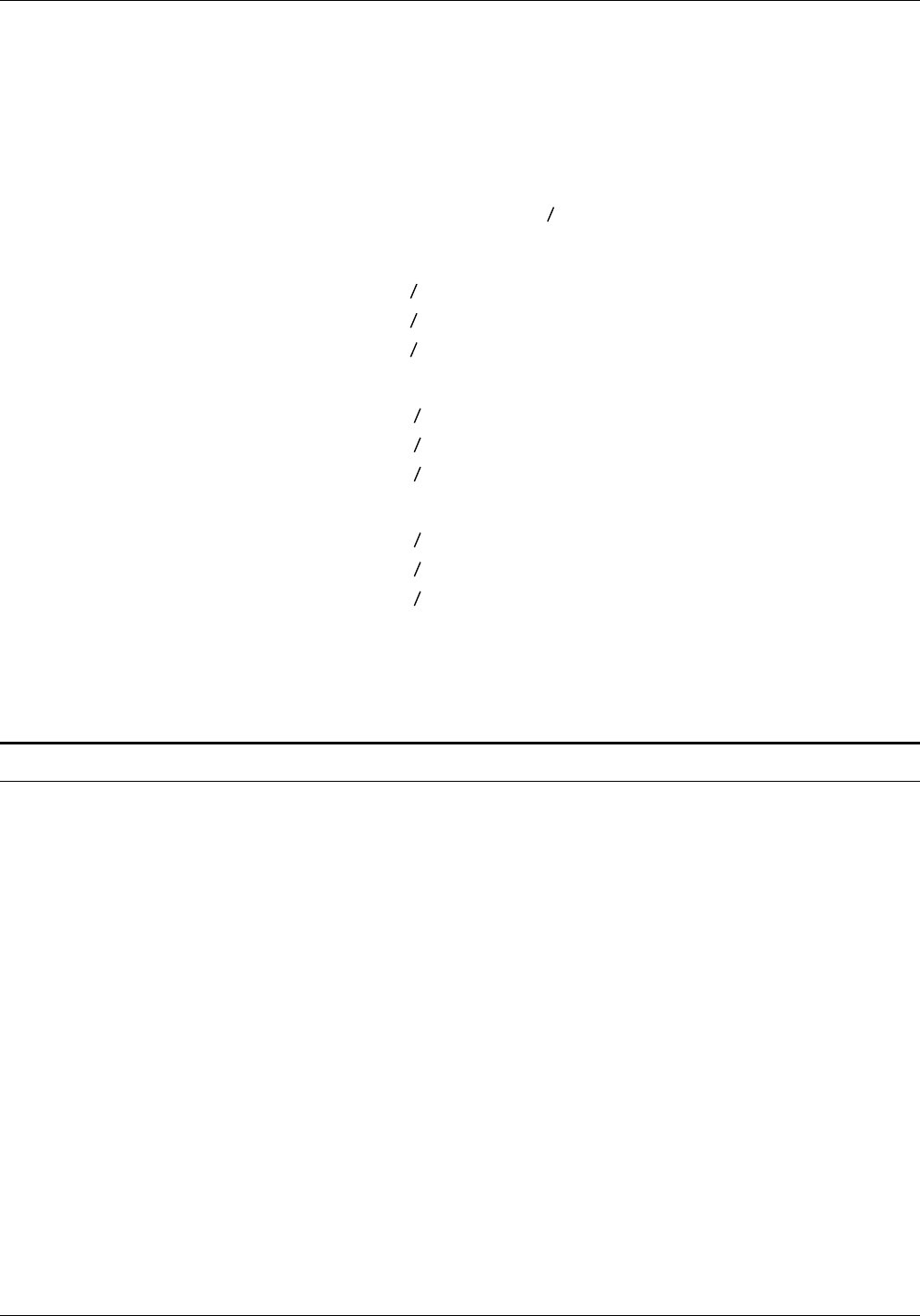
TROUBLESHOOTING
Example Text might be spaced at four dots, while the line spacing is really
59 dots. It seems paradoxical to designate that text be spaced at
four dots and create a form that actually has 59 dots of spacing.
However, you can do this by using blank lines. A small line
spacing along with blank lines allows you to get positioning
control and forces visual centering of text within a box.
b
The following statements provide an example of how this
technique is used ( represents a blank line).
TEXT SPACED AT 4 DOTS IN BOX 10, 10
b
b
b
‘TEXT LINE 1’
b
b
‘TEXT LINE 2’
b
b
b
b
As many blank lines may be used before, between, and after lines
of text as are needed to obtain the desired visual effect.
Shading factors
You may sometimes want to use shading in a form, but it
requires using a large amount of the form image buffer. Also,
the space used increases if portrait rather than landscape shading
is used.
Landscape shading The basic element used in shading is a 32-by-32-dot character for
dots. This character can be repeated in a landscape direction up
to 32 times for dots. This means that in a landscape direction,
the system can shade any area from 0.1 to 3.4 inches wide with
no difference in the space used by the shading.
This facility is not available when shading is done in a portrait
direction. Portrait shading is performed on a character-by-
character basis.
Portrait shading To reduce shading and improve the visual effect of the form, end
shading before the boundary line. Separate the shading from the
surrounding lines by 0.1 to 0.2 line or character units. This makes
the shading 0.2 to 0.4 units smaller than the surrounding box and
is centered in that box. (Units referred to are lpi and cpi units.)
This sets shading back from the borders by 3 to 5 dots.
4-12 XEROX 4050/4090/4450/4650 LPS FORMS CREATION GUIDE
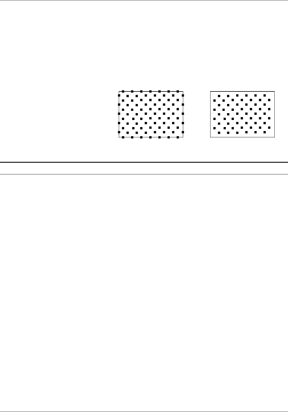
TROUBLESHOOTING
Avoiding boundary line Terminating the shading before reaching the boundary line helps
density problems to avoid line density problems, conserves space in the form file
and in the form image buffer, and enhances the appearance of
the form.
Figure 4-6. Terminating shading to avoid line density
problems
Normal shading using the
same coordinates and
sizes as the box.
Early shading termination
using a smaller box for
shading.
Section factors
You can create sections to duplicate identical information on a
page. However, you should take into account the form image
buffer limitations and potential line density problems whenever
you use this feature.
A form that is made up of many sections often takes up more
space in the form image buffer than a form created without
sections. This occurs because a single long line requires less
buffer space than many short lines. When you create a form by
invoking defined sections, there is a tendency to begin and end
lines at section boundaries, even when they are continuous
through a series of sections. This is a much less efficient way to
create forms than by taking the long lines out of the sections and
drawing them as continuous lines.
A less obvious inefficiency of using the form image buffer may
occur when you have a line that switches from solid to dotted
and vice versa. The common method of creating this type of line
is to draw short segments of solid and dotted lines. This is an
inefficient use of the form image buffer even if a SOLID 0 line is
drawn first. A SOLID 0 line is useful in saving space in the line
tables, but cannot help save buffer space.
To save form image buffer space efficiently, draw a continuous
dotted line and overlay a series of short, solid line segments.
This technique makes best use of the form image buffer space,
but does not reduce the load on the imaging section of the
system. Refer to the “Scan line density” section in this chapter
for more information. In a form where there is a problem with
exceeding both form image buffer and line density restrictions,
you may have to use logos or a specialty form font.
XEROX 4050/4090/4450/4650 LPS FORMS CREATION GUIDE 4-13

TROUBLESHOOTING
Rounding measurement factors
Laser printing systems use only dot units when actually compiling
forms. Therefore, as long as all positioning commands within
FDL are defined in terms of dots or an integral number of dots,
there are no rounding problems.
Converting other unit values to dots
You can define positions in decimal-value inches, in centimeters,
in lines per inch, and in characters per inch. The LPS converts all
of these commands to dots while the form is being compiled.
Many of the possible defined values (lines per inch, centimeters,
and so forth) cannot be reduced to an integral number of dots.
For example, if a coordinate system uses 13.6 characters per inch
(cpi), that number may be translated to approximately 22.058823
dots per character unit. The compiler rounds the converted
number to the nearest whole dot before starting to compile the
form.
Example The following example illustrates the problems encountered
using the 13.6 cpi coordinate system:
AT 4 DRAW 1 HOR LINE FROM -1 TO 132 USING SOLID 1;
AT 5 DRAW 1 HOR LINE FROM -1 TO 132 USING SOLID
HAIRLINE;
AT 8 DRAW 15 VER LINES FROM 4 TO 5 USING HAIRLINE
AND REPEAT HOR EVERY 8;
In theory, this form description technique creates 14 boxes that
can be found simply by addressing the appropriate coordinates.
In fact, the coordinates of the boxes are not exactly those
expected. The boxes can be found by using the IN NEXT BOX
parameter of the TEXT IN BOX command.
The IN NEXT BOX parameter works properly because it specifies
the next adjacent box, but does not specify the coordinates of
that box. The problem in addressing coordinates is that the FDL
statement requires vertical lines every 176.47058 dots, which is
rounded down by the system to 176.00000 dots.
This difference makes it impossible for the LPS to find box 14 at
the coordinates 4, 112. There are two ways to draw the form to
overcome this problem. One way is to draw 13 lines with the
REPEAT parameter and then specify lines at 112 and 120.
Another way is to change the final statement in the following
manner:
AT 8 DRAW VER LINE FROM 4 TO 5 USING HAIRLINE AND
AT 16, 24, 32, 42, 48, 56, 72, 80, 88, 96, 104, 112, 120;
Unless a form is described with a coordinate system of only dots
or an integral number of dots, the REPEAT parameter cannot be
used to draw boxes that must be referenced by their
coordinates.
4-14 XEROX 4050/4090/4450/4650 LPS FORMS CREATION GUIDE

TROUBLESHOOTING
Rounding variable data
Alignment problems Under certain circumstances, a form and variable data do not
align properly, even though it appears that both use the same
line spacing. This may be the result of the effects of rounding
on the line spacing.
As an example, construct a form with a grid unit of 13.6 cpi and
9 lpi. Horizontal lines are specified at 0, 4, 7, 10, 13, 16, 19, 22,
25, 28, 31, 34, 37, 40, 43, 46, 49, 52, 55, 58, 61, 64, and 67. The
data is printed with an override line spacing of “9.”
The natural assumption is that the form and the variable data line
up. However, when the variable data is merged with the form, it
tends to drift up the page. The reason for this is rounding.
Specifying 9 lines per inch for the variable data means that the
LPS is requested to place data at approximately 33.333333 dots.
The system rounds this number down to 33 dots per line.
Meanwhile, in FDL, rounding does not take place until it is time
to resolve specifications for the form to a dot address.
Note that variable data has a line spacing value that is computed
as dots per line, and rounding is done on that value. In FDL, the
rounding takes place only when it is needed to resolve to a dot
address and, therefore, might involve more than one line at a
time.
For example, the line drawn at 43 is assigned to scan line 1433
using the following formula:
(43 * 300) / 9 = 12900 / 9 = 1433.3333 or 1433
The equivalent line positioning for the variable data is computed
with the following method:
43 * (300 / 9) = 43 * 33 = 1419
This yields an error that increases as calculation proceeds down
the page.
Furthermore, in the example form, if we had drawn lines with a
REPEAT EVERY 3 LINES command, the uneven dot value
(33.333333 dots per line) would not have been rounded off
because rounding would not have been performed until it was
time to resolve the specification to a dot address. The dot
address for three lines is an even 100 dots. So, the lines for the
form would be drawn at exactly 100 dots, and the variable data,
on the other hand, would be using a 99-dot spacing.
Avoiding imperfect alignment The best way to ensure that a form and variable data share the
same coordinate system is to define both in terms of an integral
number of dots. It is also important to know when rounding will
affect the alignment of the variable data and the form. In the
example, the only way to make the form match the lines of data
is to set the line spacing for both at 33 dots.
If variable data does not line up properly with a form, and it
appears that both are using the same line spacing, find out what
the dot value is. It is most likely in such cases that the difficulty
is a variation in defining the coordinate system resulting from
rounding, and is not a software problem.
XEROX 4050/4090/4450/4650 LPS FORMS CREATION GUIDE 4-15
TROUBLESHOOTING
FDL statistics
If a form is compiled successfully, the following FDL statistics are
displayed on the summary sheet.
• Size of the source output file (FSL)
• Size of the printable form file (FRM)
• Size of the form image buffer
• Amount of font memory used by the form.
Grid unit scaling
Table 4-3 shows grid unit scaling specifications when the grid
parameters are omitted or specified.
Table 4-3 Grid unit scaling specifications
Grid unit specification System response
Omitted: default scaling When the system receives the FORM id command, it sets grid
scaling to that of FMT1; if it subsequently receives the
PORTRAIT command, it sets the scale to that of FMT6.
Specified in GRID command Replaces default scaling.
Specified in BOX or LINE
command (IN unit) Replaces GRID command scaling for that command only
(becomes the default scaling).
Specified for a parameter Overrides any scaling specified via GRID, BOX, or LINE
commands for the parameter only. Examples:
GRID 1 INCH;
AT 2 CM LINE FROM 3 TO 1500 DOTS;
COMMENT EQUIVALENT TO: AT 2 CM LINE
FROM 3 INCHES TO 1500 DOTS;
AT 2 LINE IN CM FROM 3 INCHES TO 1500 DOTS;
COMMENT EQUIVALENT TO: AT 2 CM LINE FROM 3 INCHES TO
1500DOTS;
4-16 XEROX 4050/4090/4450/4650 LPS FORMS CREATION GUIDE
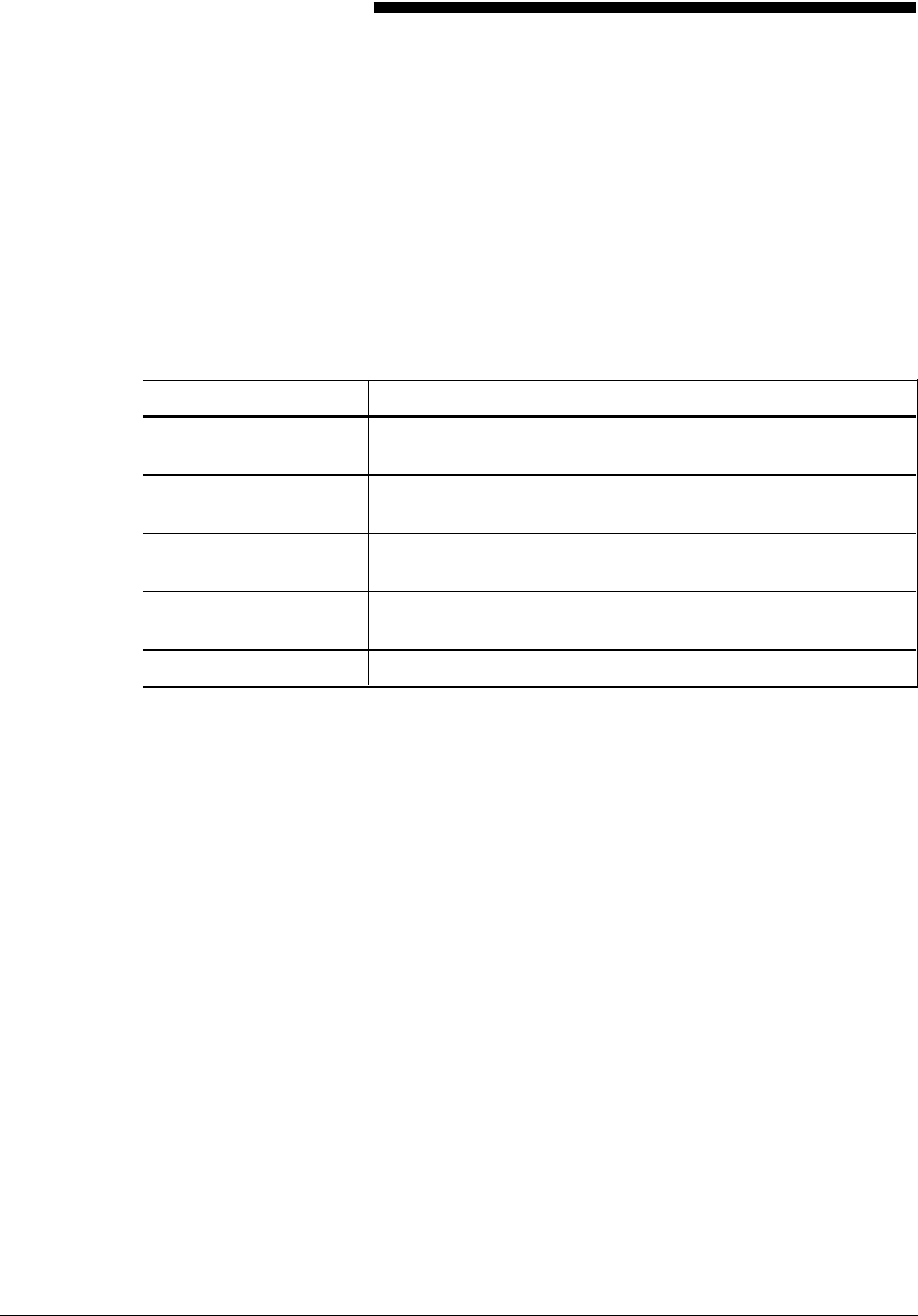
A. FDL command syntax summary
This appendix contains an alphabetized summary of the Forms
Description Language (FDL) commands syntax described in this
guide.
The conventions and definitions used to describe the commands
are shown in table A-1.
Table A-1. FDL command syntax conventions
Syntax Meaning
UPPERCASE BOLD BLUE Required words (keywords*) in the command syntax appear in
uppercase bold blue.
... Ellipses indicate that you can repeat a parameter option, or list a
series of parameter options.
Lowercase black italics Word, character, or phrase, (variable information) in lowercase
black italic to be replaced by a value.
UPPERCASE BLUE ITALIC Optional required words (keywords) in the command syntax
appear in uppercase blue italic.
The carat character represents a required space.
*Keywords may be abbreviated to the first three characters
(except for FMTn). Refer to the “Syntax ambiguities” section
in the “Troubleshooting” chapter.
XEROX 4050/4090/4450/4650 LPS FORMS CREATION GUIDE A-1
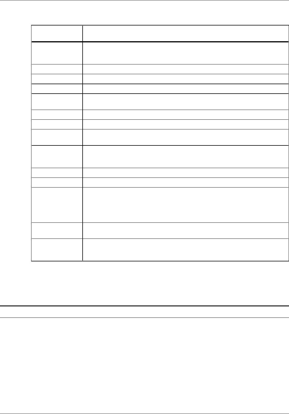
FDL COMMAND SYNTAX SUMMARY
Table A-2. FDL command syntax
Command Syntax
BOX AT y unit x unit DRAW n BOXES IN unit p unit WIDE BY q
unit HIGH USING type thickness SHADING density AND
REPEAT direction AT ca unit ca unit ... EVERY ci unit;
COMMENT COMMENT text;
END END;
FONT FONTS id;
FORM/
RESOLUTION FORM name;
FORM name RESOLUTION IS value SPI;
GRAPHIC GRAPHIC name AT vpos unit hpos unit SCALE IS n/d;
GRID GRID UNIT IS format id ORIGIN y unit x unit;
LANDSCAPE/
PORTRAIT orientation PAGE SIZE IS n WIDE BY m HIGH;
LINE AT co unit DRAW n direction LINES IN unit FROM cs unit
TO ce unit USING type thickness AND REPEAT repeat
direction AT ca unit ... EVERY ci unit;
LOGO LOGO id AT y unit x unit;
PAPER PAPER SIZE IS value;
SECTION BEGIN SECTION id;
or
DO SECTION id AT y unit x unit;
or
END SECTION id;
TEXT AT direction TEXT SPACED d units PER LINE ALIGNED alignment
USING FONT n AT y unit x unit ‘text’ ‘text’ ...;
TEXT IN BOX direction TEXT SPACED d units PER LINE ALIGNED alignment
USING FONT n IN position BOX y unit x unit ‘text’ ‘text’ ...
IN NEXT direction BOX ‘text’ ‘text’ ...;
Reference Refer to the “Forms Description Language” chapter for a detailed
explanation of each command syntax.
Compiling commands syntax
To invoke the forms compiler, enter the following command at
the LPS keyboard. The entire command must fit on one line.
FDL filename NOPRINT TRAY DEBUG XPAN NOSOURCE PROOF SIMPLEX RES=value
To print a stored form, enter the following:
SAMPLE filename.FRM
Reference Refer to the “Compiling and printing forms” chapter for more
information on compiling commands.
A-2 XEROX 4050/4090/4450/4650 LPS FORMS CREATION GUIDE
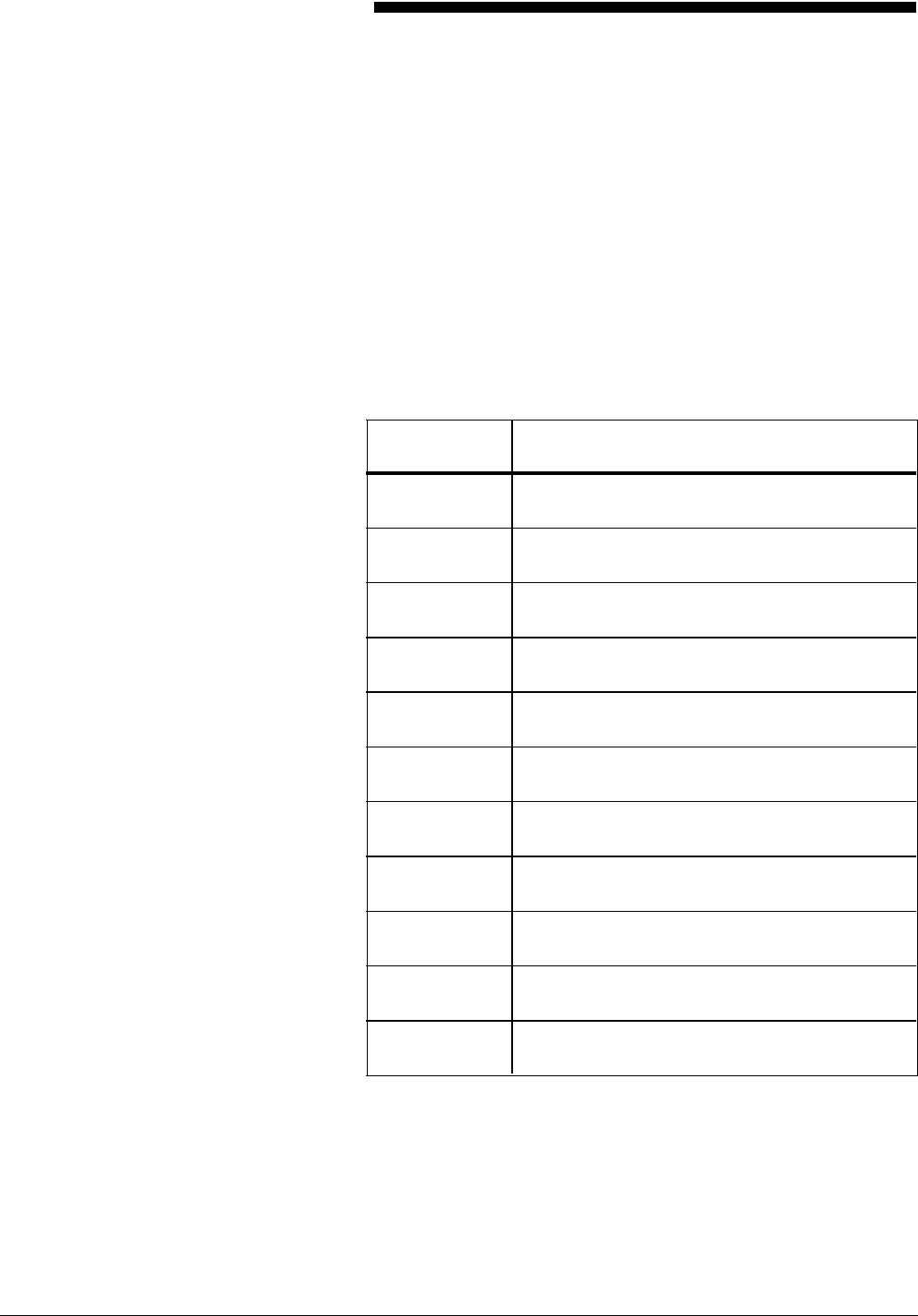
B. System default summary
This appendix lists the default parameters that the system
automatically substitutes when specifications are omitted in FDL
commands. Grid unit dimensions are rounded to the nearest
tenth.
The grid and origin substitutions made when printing on 8.5 by
11 inch/216 by 279 mm paper are shown in table B-1.
Table B-1. Grid and origin substitutions for 8.5 by 11
inch/216 by 279 mm paper
Specification Substitution
FMT1 LANDSCAPE; GRID UNIT IS 13.6 CPI, 8.1 LPI,
ORIGIN 0.18 INCH, 0.66 INCH;
FMT2 LANDSCAPE; GRID UNIT IS 15 CPI, 8.1 LPI,
ORIGIN 0.18 INCH, 0.50 INCH;
FMT3 LANDSCAPE; GRID UNIT IS 13.6 CPI, 10.7 LPI,
ORIGIN 0.14 INCH, 0.66 INCH;
FMT4 LANDSCAPE; GRID UNIT IS 15 CPI, 10.7 LPI,
ORIGIN 0.14 INCH, 0.50 INCH;
FMT5 LANDSCAPE; GRID UNIT IS 10 CPI, 6 LPI,
ORIGIN 0.17 INCH, 0.50 INCH;
FMT6 PORTRAIT; GRID UNIT IS 13.6 CPI, 8.1 LPI,
ORIGIN 0.57 INCH, 0.58 INCH;
FMT7 PORTRAIT; GRID UNIT IS 12 CPI, 6 LPI,
ORIGIN 0.50 INCH, 0.50 INCH;
FMT8 PORTRAIT; GRID UNIT IS 10 CPI, 6 LPI,
ORIGIN 0.50 INCH, 0.50 INCH;
FMT9 LANDSCAPE; GRID UNIT IS 20 CPI, 10 LPI,
ORIGIN 0.25 INCH, 0.25 INCH;
FMT10 PORTRAIT; GRID UNIT IS 17.6 CPI, 12.5 LPI,
ORIGIN 0.22 INCH, 0.51 INCH;
FMT11 PORTRAIT; GRID UNIT IS 20 CPI, 12.5 LPI,
ORIGIN 0.57 INCH, 0.39 INCH;
XEROX 4050/4090/4450/4650 LPS FORMS CREATION GUIDE B-1
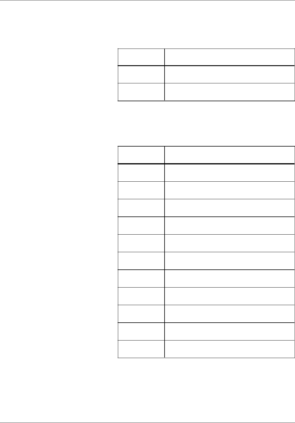
SYSTEM DEFAULT SUMMARY
The grid and origin substitutions made when printing on 8.5 by
14-inch/216 by 356 mm paper are shown in table B-2.
Table B-2. Grid and origin substitutions for 8.5 by 14
inch/216 by 356 mm paper
Specification Substitution
FMT12 LANDSCAPE; GRID UNIT IS 13.6 CPI, 8.1 LPI,
ORIGIN 0.18 INCH, 0.66 INCH;
FMT13 PORTRAIT; GRID UNIT IS 13.6 CPI, 8.1 LPI,
ORIGIN 0.57 INCH, 0.58 INCH;
The grid and origin substitutions made when printing on 8.27 by
11.69 inch/A4 paper are shown in table B-3.
Table B-3. Grid and origin substitutions for 8.27 by 11.69
inch/A4 paper
Specification Substitution
FMT1A LANDSCAPE; GRID UNIT IS 12.5 CPI, 8.3 LPI,
ORIGIN 0.46, 1.45 CM; (0.18, 0.57 INCH)
FMT2A LANDSCAPE; GRID UNIT IS 14.3 CPI, 8.3 LPI,
ORIGIN 0.46, 1.53 CM; (0.18, 0.60 INCH)
FMT3A LANDSCAPE; GRID UNIT IS 12.5 CPI, 11.1 LPI,
ORIGIN 0.46, 1.45 CM; (0.18, 0.57 INCH)
FMT4A LANDSCAPE; GRID UNIT IS 14.3 CPI, 11.1 LPI,
ORIGIN 0.46, 1.53 CM; (0.18, 0.60 INCH)
FMT5A LANDSCAPE; GRID UNIT IS 10 CPI, 6 LPI,
ORIGIN 0.56, 2.16 CM; (0.22, 0.85 INCH)
FMT6A PORTRAIT; GRID UNIT IS 13.6 CPI, 8.1 LPI,
ORIGIN 2.32, 1.17 CM; (0.91, 0.46 INCH)
FMT7A PORTRAIT; GRID UNIT IS 12 CPI, 6 LPI,
ORIGIN 2.16, 1.00 CM; (0.85, 0.39 INCH)
FMT8A PORTRAIT; GRID UNIT IS 10 CPI, 6 LPI,
ORIGIN 2.16, 1.00 CM; (0.85, 0.39 INCH)
FMT9A LANDSCAPE; GRID UNIT IS 20 CPI, 10 LPI,
ORIGIN 0.36, 2.16 CM; (0.14, 0.85 INCH)
FMT10A PORTRAIT; GRID UNIT IS 17.6 CPI, 12.5 LPI,
ORIGIN 1.45, 1.00 CM; (0.57, 0.39 INCH)
FMT11A PORTRAIT; GRID UNIT IS 20 CPI, 12.5 LPI,
ORIGIN 1.44, 1.00 CM; (0.57, 0.39 INCH)
B-2 XEROX 4050/4090/4450/4650 LPS FORMS CREATION GUIDE
SYSTEM DEFAULT SUMMARY
Substitutions made for all paper sizes are shown in table B-4.
Table B-4. Grid and origin substitutions for all paper sizes
Specification Substitution
FORM id; FORM id; GRID FMT1;
FORM id; PORTRAIT; FORM id; PORTRAIT; GRID FMT6;
Page orientation not specified Landscape
PAPER SIZE not specified Sysgen-specified paper size is assumed
PAPER SIZE not specified Virtual page size is set to sysgen-specified paper
size
Explicit GRID UNIT measurement is specified,
and ORIGIN is not specified Form origin is set to virtual page origin
GRID format-id is specified, and ORIGIN is not
specified Form origin is set to specified format-id BEGIN
values
No GRID UNIT or format-id is specified, and
ORIGIN is specified Grid unit dimensions are set by FMT1
(landscape) or FMT6 (portrait)
No GRID command is specified Grid unit dimensions and form origin are set by
FMT1 (landscape) or FMT6 (portrait)
No unit specified in the ORIGIN parameter of
the GRID command or the PAGE SIZE parameter
of the LANDSCAPE or PORTRAIT command
Inches
No line direction Horizontal and repeat vertically
No line/box thickness SOLID 1
No direction for box repeat Repeat box horizontally
No text direction Horizontal text
No box text alignment Aligned centered in the box
No font index specified in the TEXT command Current font in use
Unit not specified in the SPACED parameter of
the TEXT command Dots
No units specified in the LOGO command Grid unit
XEROX 4050/4090/4450/4650 LPS FORMS CREATION GUIDE B-3

C. Sample form creation
This appendix reviews the commands discussed earlier in this
guide, and illustrates a sample form along with the entire Forms
Source Library (FSL) that created it.
Practice entering the Forms Description Language (FDL)
commands that instruct the LPS to produce a sample form
accurately. Refer to the command definitions discussed earlier in
this guide as needed. Enter the commands as shown in the
sample FSL to produce the form.
You must be familiar with the LPS Editor utility or the editor at
your host.
The sample form that you create is shown in figure C-1, in
reduced size; your form will be actual size.
Figure C-1. Earnings register
XEROX 4050/4090/4450/4650 LPS FORMS CREATION GUIDE C-1
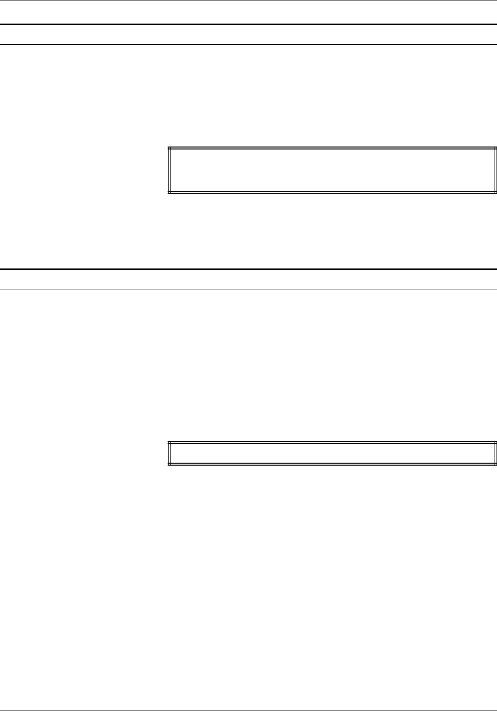
SAMPLE FORM CREATION
Writing the setup commands
Recall that the setup commands precede the form description
commands for lines, boxes, and text. In general, the setup
commands specify the parameters which describe the form.
Invoke the Editor utility and enter the commands shown in figure
C-2.
Figure C-2. Setup commands
FORM 1STFRM;
GRID FMT1;
FONTS UN114A,UN106A,UN104C;
Notice that the PORTRAIT or LANDSCAPE command and the
PAPER command are omitted. These commands are optional,
and, when omitted, the system uses the default values.
Using the COMMENT command
Comments enable you to include messages or reminders in your
source statement that help you organize your FDL commands
logically. These comments are not printed on the form but can
be useful if you or someone else modifies the form later.
If the semicolon is omitted, the forms compiler cannot determine
where the comment ends and may treat commands as
comments.
Enter the COMMENT shown in figure C-3. The comment
indicates that horizontal lines are coded next.
Figure C-3. COMMENT command
COMMENT *** DRAW HORIZONTAL LINES ***;
C-2 XEROX 4050/4090/4450/4650 LPS FORMS CREATION GUIDE

SAMPLE FORM CREATION
Drawing lines
LINE commands are used to construct horizontal and vertical
lines which, in turn, are used to construct boxes.
Drawing horizontal lines
Enter the horizontal line commands shown in figure C-4. You
have the option of abbreviating the commands to the first three
characters.
Figure C-4. HORIZONTAL LINE command
COMMENT *** DRAW HORIZONTAL LINES ***;
AT 7 DRAW 18 LINES FROM 0 TO 132 USING HAI AND REPEAT EVE 3;
AT 8 DRAW 18 LINES FROM 0 TO 24 USI HAI AND REPEAT EVE 3;
AT 9 DRAW 18 LINES FROM 0 TO 24 USING HAI AND REPEAT EVE 3;
Drawing vertical lines
Insert another COMMENT to indicate that vertical lines are to be
coded next, then enter the vertical line commands shown in
figure C-5.
Figure C-5. VERTICAL LINE command
COMMENT *** DRAW VERTICAL LINES ***;
AT 24 DRAW VER LINE FROM 5 TO 61 USING HAI;
AT 32 DRAW 11 VER LINE FROM 5 TO 61 USING HAI AND REPEAT EVE 10;
AT 29 DRAW VER LINE FROM 10 TO 61 USI BRO HAI;
AT 38 DRAW 10 VER LINE FROM 10 TO 61 USI BRO HAI AND REPEAT EVE 10;
AT 8 DRAW 18 VER LINE FROM 8 TO 9 USI HAI AND REPEAT VER EVE 3;
AT 19 DRAW 18 VER LINE FROM 8 TO 9 USI HAI AND REPEAT VER EVE 3;
XEROX 4050/4090/4450/4650 LPS FORMS CREATION GUIDE C-3
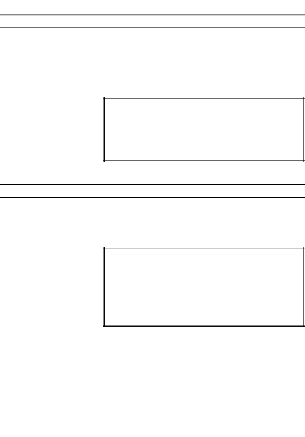
SAMPLE FORM CREATION
Drawing boxes
Use the BOX command to construct individual, standalone boxes
or boxes that share common sides. You can also create a
shaded area or construct an invisible box to place “floating” text
such as titles conveniently.
Enter the following COMMENT and BOX command, as shown in
figure C-6.
Figure C-6. BOX command
COMMENT *** DRAW BOXES ***;
AT 2,2 DRAW BOX 35 WIDE BY 2 HIGH USI HAIRLINE;
AT 2,82 DRAW BOX 50 WIDE BY 2 HIGH USI HAI;
AT 5,0 DRAW BOX 132 WIDE BY 56 HIGH USI HAI;
AT 5.1,0 BOX 132 WIDE BY 1.8 HIGH USI SHADING;
AT 10.1,0 DRAW 9 BOXES 132 WIDE BY 2.8 HIGH USI SOL HAI
INK 'BLUE' AND FILL USING INK 'XEROX.PICTORIAL.PALE BLUE'
AND REPEAT VER EVE 6;
Placing text at a location
Use the TEXT AT command to place text at an exact location.
Enter the COMMENT and TEXT AT command, as shown in figure
C-7.
Figure C-7. TEXT AT command
COMMENT *** TEXT AT COMMAND ***;
TEXT USING FONT 2 AT 2,2.5 'COMP.';
TEXT USING FONT 2 AT 2,11 'BR.';
TEXT USING FONT 2 AT 2,14 'DEPT.';
TEXT USING FONT 2 AT 2,22 'DATE';
TEXT USING FONT 2 AT 2,30 'PP';
TEXT USING FONT 2 AT 2,34 'PAGE';
TEXT USING FONT 1 INK 'BLUE' AT 3,47 'EARNINGS REGISTER';
TEXT USING FONT 2 AT 61,0 '7860-143-1';
VER TEXT USING FONT 3 AT 66,-5 'F8662';
C-4 XEROX 4050/4090/4450/4650 LPS FORMS CREATION GUIDE
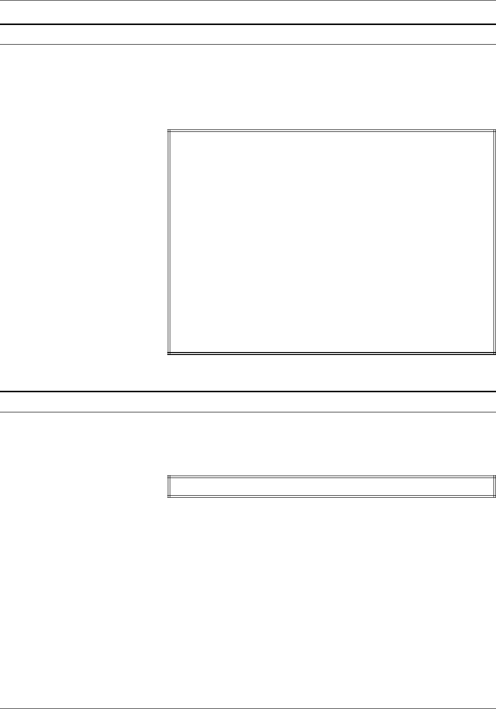
SAMPLE FORM CREATION
Placing text in a box
The TEXT IN BOX command allows you to place text at a
particular location within a box that was previously described.
Enter the COMMENT and TEXT IN BOX commands, as shown in
figure C-8.
Figure C-8. TEXT IN BOX command
COMMENT *** TEXT IN BOX COMMANDS ***;
TEXT USI FONT 2 IN BOX 5.1,24 'THIS PAY' BOX 'REGULAR' BOX
'OVERTIME';
TEXT USI FONT 2 IN BOX 7,0 'NAME'
BOX 'GROSS' 'ADJ. NET' 'NET PAY'
BOX 'UNITS-UNITS YTD' 'CURRENT AMT.' 'YTD AMOUNT'
BOX 'UNITS-UNITS YTD' 'CURRENT AMT.' 'YTD AMOUNT'
BOX 'UNITS-UNITS YTD' 'CURRENT AMT.' 'YTD AMOUNT'
BOX 'UNITS-UNITS YTD' 'CURRENT AMT.' 'YTD AMOUNT'
BOX 'UNITS-UNITS YTD' 'CURRENT AMT.' 'YTD AMOUNT'
BOX 'UNITS-UNITS YTD' 'CURRENT AMT.' 'YTD AMOUNT'
BOX 'UNITS-UNITS YTD' 'CURRENT AMT.' 'YTD AMOUNT'
BOX 'UNITS-UNITS YTD' 'CURRENT AMT.' 'YTD AMOUNT'
BOX 'UNITS-UNITS YTD' 'CURRENT AMT.' 'YTD AMOUNT'
BOX 'UNITS-UNITS YTD' 'CURRENT AMT.' 'YTD AMOUNT';
TEXT USI FONT 2 IN BOX 8,19 'EMP.##';
TEXT USING FONT 2 IN LEFT CENTER BOX 9,0 'SAL/RATE';
TEXT USING FONT 2 IN BOX 9,0 'GROSS YTD';
Using the END command
The END command is the final command. Enter END; and you
are done!
Figure C-9. END command
END;
XEROX 4050/4090/4450/4650 LPS FORMS CREATION GUIDE C-5
SAMPLE FORM CREATION
Compiling the form
This exercise gives you practice using most of the FDL
commands discussed throughout this guide.
The next step is to compile the .FSL which produces a sample of
the form, provided there are no syntax errors. The summary
statement also prints any errors.
After you have entered the END command, SAVE, CLEAR, and
END the editing session, as shown in figure C-10.
Figure C-10. SAVE, CLEAR, and END commands
END;
SAVE 1STFRM.FSL
CE
FDL 1STFRM,TRA
CE is an abbreviation for CLEAR and END.
Do not be surprised if you inadvertently omit a semicolon or
misspell a word. The system indicates where the error occurred
and you can easily go back into the form and correct the error.
If there are errors, at the OS1000 READY FOR COMMANDS message on
the LPS user interface, enter the following:
EDIT 1STFRM.FSL
The .FSL file is displayed. When you identify where the error
occurred, modify that record, then SAVE, CLEAR, and END the
editing session. Since this FSL already exists, use the abbreviated
method to SAVE, CLEAR, and END (SCE), as shown in figure C-
11.
Figure C-11. SAVE, CLEAR, and END (SCE) commands
END;
SCE
FDL 1STFRM,TRA
When the form compiles error-free, your form prints successfully.
Figure C-12 illustrates the complete .FSL.
C-6 XEROX 4050/4090/4450/4650 LPS FORMS CREATION GUIDE

SAMPLE FORM CREATION
Figure C-12. Source statement (1STFRM.FSL)
FDL VERSION B03 13:13 30-APR-XX PAGE 1
DISK-ID: ARIEL VX.7 R9.7 REL #5 XX/XX/XX
1 FORM 1STFRM; 000010
2 GRID FMT1; 000020
3 FONTS UN114A,UN106A,UN104C; COMMENT ***DRAW HOR LINES***; 000030
4 AT 7 DRAW 18 LINES FROM 0 TO 132 USING HAI AND REPEAT EVE 3; 000040
5 AT 8 DRAW 18 LINES FROM 0 TO 24 USING HAI AND REPEAT EVE 3; 000050
6 AT 9 DRAW 18 LINES FROM 0 TO 24 USING HAI AND REPEAT EVE 3; 000060
8 COMMENT *** DRAW VERTICAL LINES *** 000080
9 AT 24 DRAW VER LINE FROM 5 TO 61 USING HAI 000090
10 AT 32 DRAW 11 VER LINE FROM 5 TO 61 USING HAI AND REPEAT EVE 10; 000100
11 AT 29 DRAW VER LINE FROM 10 TO 61 USING BRO HAI; 000110
12 AT 38 DRAW 10 VER LINE FROM 10 TO 61 USI BRO HAI AND REPEAT EVE 10; 000120
13 AT 8 DRAW 18 VER LINE FROM 8 TO 9 USI HAI AND REPEAT VER EVE 3; 000130
14 AT 19 DRAW 18 VER LINE FROM 8 TO 9 USI HAI AND REPEAT VER EVE 3; 000140
15 COMMENT ***DRAW BOXES ***; 000150
16 AT 2,2 DRAW BOX 35 WIDE BY 2 HIGH USI HAIRLINE; 000160
17 AT 2,82 DRAW BOX 50 WIDE BY 2 HIGH USI HAI; 000170
18 AT 5,0 DRAW BOX 132 WIDE BY 56 HIGH USI HAI; 000180
19 AT 5.1,0 BOX 132 WIDE BY 1.8 HIGH USI SHADING; 000190
20 AT 10.1,0 DRAW 9 BOXES 132 WIDE BY 2.8 HIGH USI SOL HAI 000200
21 INK 'BLUE' AND FILL USING INK 'XEROX.PICTORIAL.PALE BLUE' 000210
22 AND REPEAT VER EVE 6; 000220
23 COMMENT *** TEXT AT COMMAND ***; 000230
24 TEXT USING FONT 2 AT 2,2.5 'COMP.'; 000240
25 TEXT USING FONT 2 AT 2,11 'BR.'; 000250
26 TEXT USING FONT 2 AT 2,14 'DEPT.'; 000260
27 TEXT USING FONT 2 AT 2,22 'DATE'; 000270
28 TEXT USING FONT 2 AT 2,30 'PP'; 000280
29 TEXT USING FONT 2 AT 2,34 'PAGE'; 000290
30 TEXT USING FONT 1 INK 'BLUE' AT 3,47 'EARNINGS REGISTER'; 000300
31 TEXT USING FONT 2 AT 61,0 '7860-143-1'; 000310
32 VER TEXT USING FONT 3 AT 66,-5 'F8662'; 000320
33 COMMENT *** TEXT IN BOX COMMANDS ***; 000330
34 TEXT USI FONT 2 IN BOX 5.1,24 'THIS PAY' BOX 'REGULAR' BOX 'OVERTIME'; 000340
35 TEXT USI FONT 2 IN BOX 7,0 'NAME' 000350
36 BOX 'GROSS' 'ADJ. NET' 'NET PAY' 000360
37 BOX 'UNITS-UNITS YTD' 'CURRENT AMT.' 'YTD AMOUNT' 000370
38 BOX 'UNITS-UNITS YTD' 'CURRENT AMT.' 'YTD AMOUNT' 000380
39 BOX 'UNITS-UNITS YTD' 'CURRENT AMT.' 'YTD AMOUNT' 000390
40 BOX 'UNITS-UNITS YTD' 'CURRENT AMT.' 'YTD AMOUNT' 000400
41 BOX 'UNITS-UNITS YTD' 'CURRENT AMT.' 'YTD AMOUNT' 000410
42 BOX 'UNITS-UNITS YTD' 'CURRENT AMT.' 'YTD AMOUNT' 000420
43 BOX 'UNITS-UNITS YTD' 'CURRENT AMT.' 'YTD AMOUNT' 000430
44 BOX 'UNITS-UNITS YTD' 'CURRENT AMT.' 'YTD AMOUNT' 000440
45 BOX 'UNITS-UNITS YTD' 'CURRENT AMT.' 'YTD AMOUNT' 000450
46 BOX 'UNITS-UNITS YTD' 'CURRENT AMT.' 'YTD AMOUNT'; 000460
47 TEXT USING FONT 2 IN BOX 8,19 'EMP.##'; 000470
48 TEXT USING FONT 2 IN LEFT CENTER BOX 9,0 'SAL/RATE'; 000480
49 TEXT USING FONT 2 IN BOX 9,0 'GROSS YTD'; 000490
50 END; 000500
XEROX 4050/4090/4450/4650 LPS FORMS CREATION GUIDE C-7
D. FDL capacity limits
The available memory space imposes the following maximums for
use, as shown in table D-1:
Table D-1. Capacity limits
Item Maximum
Text Buffer capacity: 512 bytes
Lines per TEXT statement: 64
Space allocation TEXT AT command: 16 bytes + S1 + S2 . . . Sn
TEXT IN BOX command: 18 bytes + S1 + S2 . . . Sn (1st box)
6 bytes + S1 + S2 . . . Sn (second and
all succeeding boxes)
. . .where
n bytes is fixed overhead.
S is number of characters > 2 in a text
string, rounded to a multiple of two.
Sections Definitions: 8 per form
Invocations: No limit
Lines Horizontal: 2000
Vertical: 2000
Fonts and logos 84
This number may vary, depending on memory capacity and use;
however, you cannot exceed 84 fonts and logos.
XEROX 4050/4090/4450/4650 LPS FORMS CREATION GUIDE D-1
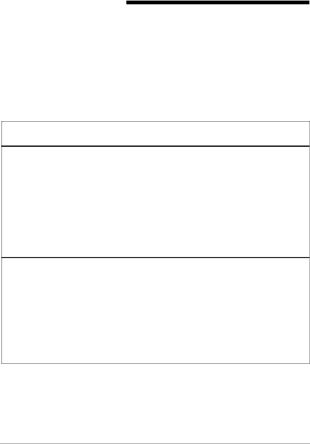
E. Standard print formats
Predefined print formats that provide commonly used impact
printer conversion formats for use with specific page sizes and
orientations are provided on the Operating System Software
(OSS).
Table E-1. Standard LPS print formats
Format ID No. of
lines No. of
columns lpi cpi Point
size1Page size and
orientation2BEGIN
values (y,x) Default
font ID
FMT1 66 132 8.1 13.6 9 11 x 8.5 in. (.18,.66) L0112B
FMT2 66 150 8.1 15 9 11 x 8.5 in. (.18,.50) L0212A
FMT3 88 132 10.7 13.6 7 11 x 8.5 in. (.14,.66) L0312A
FMT4 88 150 10.7 15 7 11 x 8.5 in. (.14,.50) L0412A
FMT5 49 100 6 10 12 11 x 8.5 in. (.17,.50) L0512A
FMT6 80 100 8.1 13.6 9 8.5 x 11 in. (.57,.58) P0612A
FMT7 60 90 6 12 12 8.5 x 11 in. (.50,.50) P07TYA
FMT8 60 75 6 10 12 8.5 x 11 in. (.50,.50) P0812A
FMT9 80 200 10.0 20.0 7 11 x 8.5 in. (.25,.25) L0912A
FMT10 132 132 12.5 17.6 6 8.5 x 11 in. (.22,.51)P1012A
FMT11 132 150 12.5 20 6 8.5 x 11 in. (.22,.50) P1112A
FMT12 66 172 8.1 13.6 9 14 x 8.5 in. (.18,.66) L0112B
FMT13 104 100 8.1 13.6 9 8.5 x 14 in. (.57,.58) P0612A
A4 formats
FMT1A 66 132 8.3 12.5 9 297 x 210 mm (.18,.57) R112BL
FMT2A 66 150 8.3 14.3 9 297 x 210 mm (.18,.60) R212BL
FMT3A 88 132 11.1 12.5 7 297 x 210 mm (.18,.57) R312BL
FMT4A 88 150 11.1 14.3 7 297 x 210 mm (.18,.60) R412BL
FMT5A 48 100 6 10 12 297 x 210 mm (.22,.85) R512BL
FMT6A 80 100 8.1 13.6 9 210 x 297 mm (.91,.46) R612BL
FMT7A 60 90 6 12 12 210 x 297 mm (.85,.39) R7TIBP
FMT8A 60 75 6 10 12 210 x 297 mm (.85,.39) R812BP
FMT9A 80 200 10.0 20.0 7 297 x 210 mm (.14,.85) R912BL
FMT10A 132 132 12.5 17.6 6 210 x 297 mm (.57,.39) RA12BP
FMT11A 132 150 12.5 20.0 6 210 x 297 mm (.57,.39) RB12BP
1 Point size is approximate.
2 First dimension given is the horizontal dimension. Therefore, 11 by 8.5 inches is landscape orientation,
while 8.5 by 11 inches is portrait orientation. For A4 paper, 297 by 210 mm is landscape, and 210 by 297
mm is portrait orientation.
XEROX 4050/4090/4450/4650 LPS FORMS CREATION GUIDE E-1
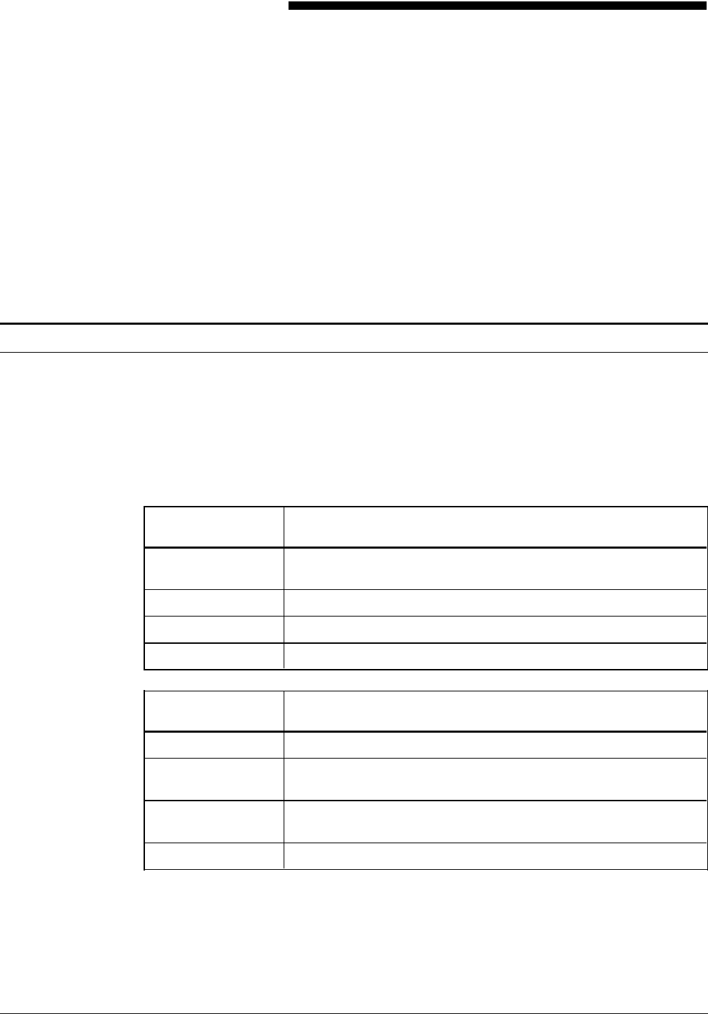
F. Support tools and measurements
There are two separate functions of form creation: forms design
and forms description. Any form can be converted to an
electronic form stored on the system by describing it in Forms
Description Language (FDL).
Forms design involves laying out and measuring a form and is
only a peripheral concern of this guide. A forms design ruler is
provided for the forms designer.
Forms design ruler
The forms design ruler is used for the following:
• Measuring character and line spacings
• Converting forms from one type of paper to another.
The ruler has eight scales, four on the front and four on the
back, as shown in table F-1.
Table F-1. Standard formats and spacings
Side 1 Formats/spacing
Scale 1–10/inch Standard computer output character spacing; can also be used
for measuring inches, graduated in tenths.
Scale 2–6/inch Standard computer output line spacing (6 lpi).
Scale 3–8/inch Standard computer output line spacing (8 lpi).
Scale 4–12/inch Can be used for 12 cpi or 12 lpi.
Side 2 Formats/spacing
Scale 5–13.6/inch Default character spacing on Xerox laser printing systems.
Scale 6–8.1/inch Default line spacing on Xerox laser printing systems (66 lines
per landscape page).
Scale 7–10.7/inch Line spacing on Xerox laser printing systems (88 lines per
landscape page).
Scale 8–15/inch Can be used for 15 cpi or 15 lpi.
The scales can be used for either character spacing or line
spacing. For example, scale 1 can be used for either 10
characters per inch (cpi) or 10 lines per inch (lpi).
XEROX 4050/4090/4450/4650 LPS FORMS CREATION GUIDE F-1

SUPPORT TOOLS AND MEASUREMENTS
Side 1 Side 1 of the ruler is typically used for measuring impact-printed
computer output reports in which the spacing is 10 cpi (scale 1)
and either 6 lpi (scale 2) or 8 lpi (scale 3).
Side 2 Side 2 should be used for measuring laser printing systems
output.
Default spacing The default spacings on the system are 13.6 cpi (scale 5) and 8.1
lpi (scale 6); they were chosen for optimal readability for the
standard computer format of 132 columns by 66 lines.
Reference Refer to the “Standard print formats” appendix for a complete list
of standard formats and spacings.
F-2 XEROX 4050/4090/4450/4650 LPS FORMS CREATION GUIDE
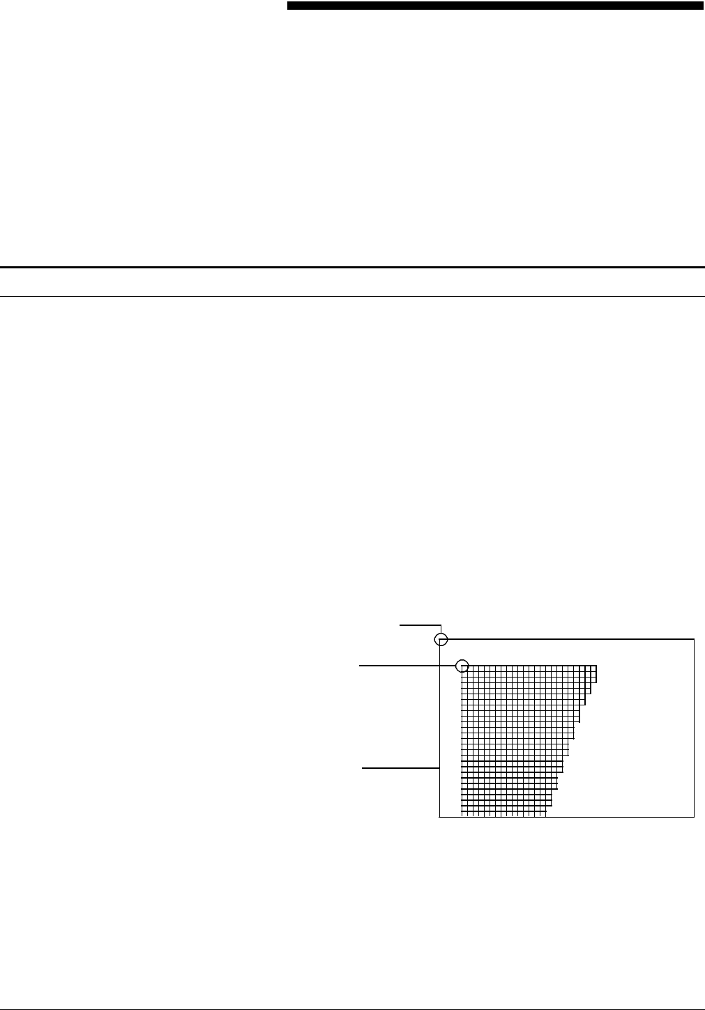
G. Command examples
The examples presented in this appendix illustrate the functions
of the FDL commands. Use these examples together with the
command information in the “Forms Description Language”
chapter.
GRID examples
The following examples illustrate how virtual page and form
origins are determined.
Reference Refer to the “Grids” section in the “Basic concepts” chapter and
the “GRID” section in the “Forms Description Language” chapter
for more information.
Example 1 LANDSCAPE;
GRID [UNIT] [IS] FMT3;
In this example, page size is not specified, and the virtual page
defaults to paper size.
FMT3 in the GRID command provides the grid size and form
origin (which is offset from the virtual page origin).
Figure G-1. Form results with grid specified, but no page
size or origin
Virtual page origin
Grid unit
dimensions
(set by FMT3)
Virtual page
(defaults to paper size)
Form origin
(set by FMT3)
Example 2 LANDSCAPE;
GRID ([UNITS] [IS] FMT1 ORIGIN [IS] 1 INCH 1 INCH;
In this example, the ORIGIN parameter in the GRID command
specifies a form origin that is offset from the virtual page origin
by one inch vertically and one inch horizontally.
Grid unit dimensions are set by FMT1.
XEROX 4050/4090/4450/4650 LPS FORMS CREATION GUIDE G-1
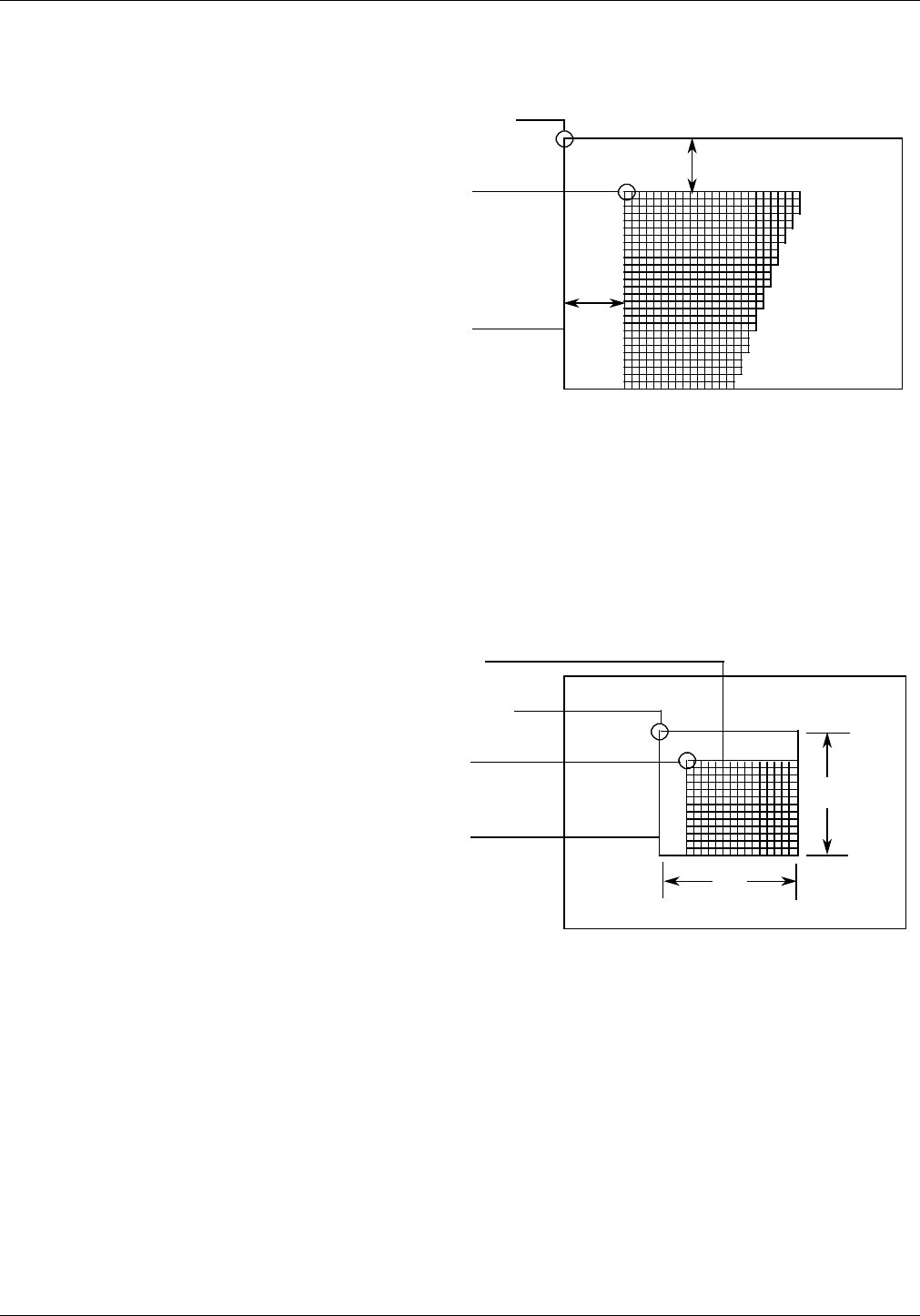
COMMAND EXAMPLES
Figure G-2. Form results with origin offset one inch from
virtual page origin
Grid unit
dimensions
(set by FMT3)
Virtual page
(defaults to paper size)
Form origin
(offset from virtual page
origin by grid origin)
1"
Virtual page origin
1"
Example 3 LANDSCAPE PAGE SIZE IS 3 INCH 3 INCH;
In this example, the landscape-oriented virtual page is centered
on the paper in accordance with the parameters in the
LANDSCAPE PAGE SIZE command.
Grid size and form origin default to FMT1.
Figure G-3. Form results with page size specified, but no
origin or grid
Virtual page origin
Grid Unit size
(set by FMT1)
Virtual page
centered on paper
Form origin
(defaults to FMT1) 3"
3"
Example 4 LANDSCAPE PAGE SIZE IS 3 INCH 3 INCH;
GRID [UNIT] [IS] 1 CM;
In this example, explicit grid unit dimensions are set by the GRID
command, and no ORIGIN parameter or predefined format is
specified. This causes the form origin to coincide with the virtual
page origin.
G-2 XEROX 4050/4090/4450/4650 LPS FORMS CREATION GUIDE
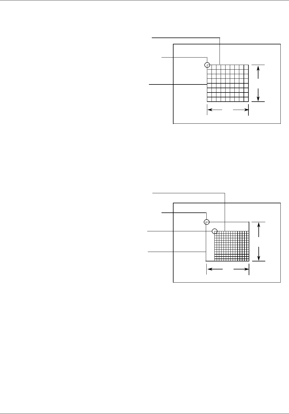
COMMAND EXAMPLES
Figure G-4. Form results with grid specified, but no origin
or format
Virtual page origin
and form origin
Grid unit size
(1 cm square)
Virtual page
centered on paper 3"
3"
Example 5 LANDSCAPE PAGE SIZE IS 3 INCH 3 INCH;
GRID [UNIT] [IS] FMT3;
In this example, FMT3 provides both the grid unit dimensions
and the form origin.
Figure G-5. Form results with grid and page size specified
Virtual page origin
Grid unit size
(set by FMT3)
Virtual page
centered on paper
Form origin
(set by FMT3) 3"
3"
Example 6 LANDSCAPE PAGE SIZE IS 3 INCH 3 INCH;
GRID [UNIT] [IS] FMT1 ORIGIN IS 1 INCH 1 INCH;
In this example, the location of the virtual page origin is
determined by the PAGE SIZE command. The form origin is
offset from the virtual page origin by one inch vertically and one
inch horizontally.
XEROX 4050/4090/4450/4650 LPS FORMS CREATION GUIDE G-3
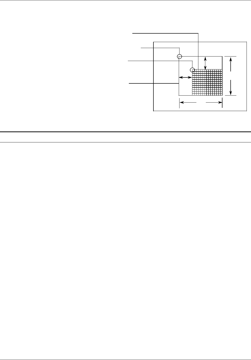
COMMAND EXAMPLES
Figure G-6. Form results with grid, origin, and page size
specified
Virtual page origin
Grid unit size
(set by FMT1)
Virtual page
centered on paper
Form origin
(offset from virtual page
origin by grid origin) 3"
3"
1"
1"
LINE examples
Example 1 AT 3 DRAW LINE FROM 4 TO 10;
AT 3 Keyword AT and the location down the
page at which the line will be placed.
DRAW Keyword DRAW.
LINE Keyword LINE or LINES. (When the
number of lines is omitted, one solid line
at the default is assumed.)
FROM 4 TO 10 Keyword FROM and the coordinates
indicating the beginning and end of the
lines.
This command specifies the drawing of a horizontal line three
grid units down from the form origin, starting four grid units to
the right of the form origin and ending 10 grid units to the right
of the form origin.
Figure G-7. Drawing a horizontal line (rows and columns)
G-4 XEROX 4050/4090/4450/4650 LPS FORMS CREATION GUIDE

COMMAND EXAMPLES
Example 2 AT 3.5 DRAW LINE IN INCHES FROM 4 TO 10;
This command specifies the drawing of a horizontal line 3.5
inches down from the form origin, beginning four inches to the
right of the form origin and ending 10 inches to the right of the
form origin.
Figure G-8. Drawing a horizontal line (inches)
Example 3 AT 2 DRAW 5 VERTICAL LINES FROM 5 TO 10 AND REPEAT
EVERY 2;
This command specifies the drawing of five vertical lines. The
first line begins two horizontal grid units to the right of the form
origin and five grid units down from the form origin, and ends
ten grid units down from the form origin. This line is repeated
every two horizontal grid unit intervals.
Figure G-9. Drawing parallel vertical lines
XEROX 4050/4090/4450/4650 LPS FORMS CREATION GUIDE G-5

COMMAND EXAMPLES
Example 4 AT 4 DRAW 5 LINES FROM 2 TO 4 AND REPEAT HORIZONTALLY
EVERY 4;
This command specifies five short lines to be drawn, each two
grid units long, with each starting point spaced four grid units
apart and separated two grid units from the end of the preceding
line.
Figure G-10. Drawing repeated horizontal lines
BOX examples
Example 1 AT 4, 6 BOX 14 WIDE BY 4 HIGH;
This command specifies a box 14 grid units wide and four grid
units high, with the upper left corner four grid units down from
the form origin and six grid units to the right of the form origin.
Figure G-11. Drawing a box
G-6 XEROX 4050/4090/4450/4650 LPS FORMS CREATION GUIDE

COMMAND EXAMPLES
Example 2 AT .5,0 DRAW 4 BOXES IN INCHES 5 WIDE BY .5 HIGH USING
SHADING AND REPEAT VERTICALLY EVERY 2;
This command specifies four 5-inch wide, .5-inch high bars
placed with the top edges at .5 inches, 2.5 inches, 4.5 inches,
and 6.5 inches.
Figure G-12. Drawing boxes
XEROX 4050/4090/4450/4650 LPS FORMS CREATION GUIDE G-7
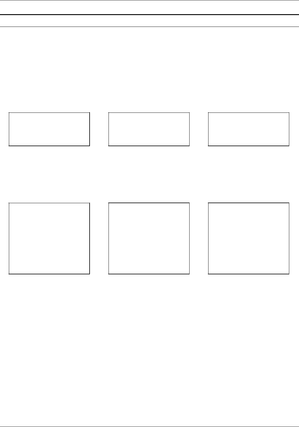
COMMAND EXAMPLES
TEXT AT examples
Figure G-13 gives the command syntax for and demonstrates
aligned text.
Figure G-13. Aligned text
1 This command produces stacked, left-aligned output beginning five grid units down from the form origin
and one grid unit to the right of the form origin, as follows.
2 To center the stacked words (the default option), an alignment need not be specified. Horizontal printing is
the default. If vertical printing is desired, it must be specified.
3 Centering is automatic. Notice how the fixed font gives a more uniform appearance.
TEXT AT 5,1 'FIRST'
'NATIONAL' 'TRUST' 'CO';
TEXT ALIGNED LEFT AT 5,1
'FIRST' 'NATIONAL' 'TRUST'
'CO';
FIRST
NATIONAL
TRUST
CO
TEXT ALIGNED RIGHT AT
5,1 'FIRST' 'NATIONAL'
'TRUST' 'CO';
FIRST
NATIONAL
TRUST
CO
Right-aligned Center-aligned2
VERTICAL TEXT ALIGNED
TOP AT 5,1 'FIRST'
'NATIONAL' 'TRUST' 'CO';
Top-aligned
FNTC
IARO
RTU
SI S
TOT
N
A
L
VERTICAL TEXT ALIGNED
BOTTOM AT 5,1 'FIRST'
'NATIONAL' 'TRUST' 'CO';
Bottom-aligned
N
A
T
FI T
IOR
RNU
SASC
TLTO
Proportional Fixed
font font
VERTICAL TEXT AT 5,1
'FIRST' 'NATIONAL'
'TRUST' 'CO';
Left-aligned1
FIRST
NATIONAL
TRUST
CO
Vertical-aligned3
G-8 XEROX 4050/4090/4450/4650 LPS FORMS CREATION GUIDE

COMMAND EXAMPLES
Figure G-14. Character block orientations for portrait and
landscape pages
This character indicates the positioning origin of the text
block.
If the font and page have the same orientation, letters appear
upright. They appear sideways or upside down if orientations
differ. Text is aligned horizontally or vertically relative to page
orientation, not relative to the font.
Portrait and inverse portrait fonts may be used with landscape
page orientation (for example, to insert labels or captions).
Likewise, landscape and inverse landscape fonts may be used
with portrait page orientation. Portrait, landscape, inverse
portrait, and inverse landscape fonts are listed in the Xerox
Laser Printing Systems Standard Font Library Font User Guide.
XEROX 4050/4090/4450/4650 LPS FORMS CREATION GUIDE G-9
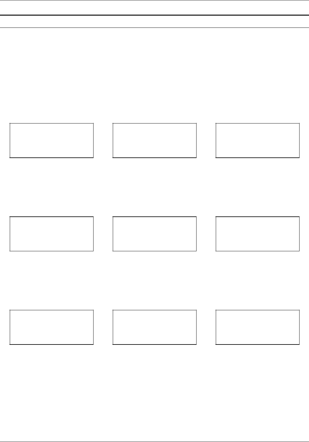
COMMAND EXAMPLES
TEXT IN BOX examples
The following examples give the command syntax and
demonstrate the nine positions in a box where text can be
placed.
Figure G-15. Text positions
Top positions
Bottom positions
TEXT ALIGNED CENTER
FONT 2 IN TOP CENTER
BOX 10,10 'PART
NUMBER’;
TEXT ALIGNED RIGHT
FONT 3 IN TOP RIGHT
BOX 5,5 'PART NUMBER';
TEXT ALIGNED LEFT FONT
1 IN TOP LEFT BOX 10,20
'PART NUMBER';
TOP LEFT TOP CENTER TOP RIGHT
TEXT FONT 1 IN CENTER
CENTER BOX 12,5 'PART
NUMBER';
TEXT ALIGNED RIGHT
FONT 1 IN RIGHT CENTER
BOX 32,3 'PART NUMBER';
RIGHT CENTERCENTER CENTER
Center positions
TEXT ALIGNED LEFT FONT
3 IN LEFT CENTER BOX
35,5 'PART NUMBER';
LEFT CENTER
TEXT ALIGNED LEFT FONT
1 IN BOTTOM LEFT BOX
20,10 'PART NUMBER';
TEXT ALIGNED CENTER
FONT 3 IN BOTTOM
CENTER BOX 40,10 'PART
NUMBER';
TEXT ALIGNED RIGHT
FONT 1 IN BOTTOM
RIGHT BOX 10,40 'PART
NUMBER';
BOTTOM CENTER BOTTOM RIGHTBOTTOM LEFT
G-10 XEROX 4050/4090/4450/4650 LPS FORMS CREATION GUIDE

Glossary
A3 International paper size measuring 297 by 420 mm or 11.69 by
16.54 inches.
A4 International paper size measuring 210 by 297 mm or 8.27 by
11.69 inches.
B4 International paper size measuring 250 by 353 mm or 9.84 by
13.9 inches.
batch processing Process that allows for repetitive operations to be performed
sequentially on batched data without much involvement from the
computer operator.
BCD Binary coded decimal.
bitmap Visual representation of graphic images in which a bit defines a
picture element (pixel) and a matrix of bits defines an image. For
example, if a bit is 1, the corresponding pixel is printed.
blocking Process of combining two or more records into a single block of
data which can moved, operated upon, stored, and so on, as a
single unit by the computer.
block length Number of characters or bytes contained in a block of data (the
block is treated as a unit within the computer). Block length is
usually invariable within a system and may be specified in units
such as records, words, computer words, or characters.
BOF Bottom of form.
BOT Beginning of tape.
bpi Bits per inch.
CCID Character Code Identifier. Code associated with the universal
identifier “Xerox” to indicate the version of the Xerox character
code standard used to code Interpress strings.
character set Set of all characters defined in a font, including alphabet,
numeric, and special characters such as symbols.
cluster Group of related feeder trays, usually containing the same size
and type of paper (stock). Each cluster has a name, consisting of
one to six alphanumeric characters.
XEROX 4050/4090/4450/4650 LPS FORMS CREATION GUIDE GLOSSARY-1

GLOSSARY
GLOSSARY-2 XEROX 4050/4090/4450/4650 LPS FORMS CREATION GUIDE
CME Entry modifying the output printing characteristics of a report on
a copy-to-copy basis.
compiler Software that translates instructions written in high-level language
into machine language for execution by a system.
Copy Modification Entry See CME.
copy-sensitive Job in which multiple copies of a report contain different data,
such as paychecks and banking statements.
cpi Characters per inch.
default Value assigned to a field by the system if no input is received
from the operator. You can change the default value of a field.
DJDE Dynamic Job Descriptor Entry. Command within an input data
stream used to modify the printing environment dynamically.
dot Picture element (pixel) imaged by a printer. The number of dots
imaged per inch measures printer resolution, for example, 300
dots per mich (dpi). See also spot.
dpi Dots per inch. Indicates the number of dots per inch displayed
on a terminal screen or printed to form a character or graphic.
dry ink Minute particles of resin and carbon black that can accept an
electrical charge and create images. Resin and carbon black or
color pigment toner are combined with developer to form the
dry ink.
duplex 1. Ability of a data communications system to send and receive
information simultaneously. 2. In printing, duplex means
printing on both sides of the paper.
Dynamic Job Descriptor Entry See DJDE.
edgemarking Use of graphic objects (usually lines or boxes) that bleed off the
edge of the physical page. See also physical page.
embedded blanks Blank spaces within a command line.
ENET Ethernet network.
EOT End of tape.
Ethernet Xerox local area network (LAN) that allows transmission of data
by cable from one device to another.

GLOSSARY
XEROX 4050/4090/4450/4650 LPS FORMS CREATION GUIDE GLOSSARY-3
FCB Forms Control Buffer. Controls the vertical format of printed
output.
FCP File Control Parameter.
FCU File Conversion Utility.
FDL Forms Description language. LPS-resident source language used
to design electronic forms. See also FSL and form.
FDR File directory.
FIS Font Interchange Standard. Defines the digital representation of
fonts and character metrics for the generation of an entire series
of Interpress fonts.
floating accent Nonspacing accent characters that can be combined with
characters and printed as a composite.
font Complete set of characters of a particular font family having the
same point size, weight, stress, and orientation.
Font Interchange Standard See FIS.
form 1. Compiled .FSL file. 2. Specific arrangement of lines, text,
and graphics stored in an electronic version. Forms can be
printed without variable data or merged with variable data during
the printing process. See also FDL and FSL.
Forms Control Buffer See FCB.
Forms Description Language See FDL.
Forms Source Library See FSL.
FSL Forms Source Library. Uncompiled collection of user-created
files containing FDL commands. See also FDL and form.
hexadecimal Numbering system with a base of 16. The numbers 10 through
15 are represented by A through F.
highlight color Printing with black plus another color. A range of colors, tints,
and shades is printed by varying the percentage of black dots,
colored dots, and the white space between the dots.
HIP Host Interface Processor.
image area Area on a physical page that may contain text or graphics.

GLOSSARY
GLOSSARY-4 XEROX 4050/4090/4450/4650 LPS FORMS CREATION GUIDE
initialize 1. To prepare a blank diskette so it can accept data. This is
usually accomplished when a program is booted. 2. To set all
information in a computer system to its starting values.
Interpress Industry-standard page description language developed by Xerox.
Interpress documents can be printed on any sufficiently powerful
printer equipped with Interpress print software.
JCB Job Control Block.
JCL Job Control Language.
JDE Job Descriptor Entry. Collection of job descriptions.
JDL Job Description Library. Collection of compiled job descriptions.
See also JSL.
JID Job Identifier.
job Synonymous with a START command, a job is a group of print
data sets called reports. A job may contain one or multiple
reports.
job control Program called into storage to prepare each job or job step to
be run.
Job Descriptor Entry See JDE.
Job Descriptor Library See JDL.
job management Collective functions of job scheduling and command processing.
Job Source Library See JSL.
JSL Job Source Library. Collection of uncompiled job descriptions.
See also JDE and JDL.
keyword Required part of a command.
label Reference to a file saved on tape or disk, a record indicating the
file name or date created, or other control information.
landscape Orientation in which text and images are positioned parallel to
the long edge of the paper.
legal size Paper size measuring 8.5 by 14 inches or 216 by 356 mm.
letter size Paper size measuring 8.5 by 11 inches or 216 by 279 mm.

GLOSSARY
XEROX 4050/4090/4450/4650 LPS FORMS CREATION GUIDE GLOSSARY-5
line feed Control character that (unless set to be interpreted as a line end)
causes the printing system to begin printing in the current
character position of the next line.
literal Alphanumeric character beginning with a letter, including an
asterisk, period, colon, or slash, and not enclosed in single
quotes.
logical page In Xerox printing systems, a logical page is a formatted page that
is smaller than the physical page. A logical page is defined by an
origin, thus allowing more than one logical page to be placed on
a physical page.
lpi Lines per inch.
LPS Laser printing system.
mask Selection of bits from a storage unit by use of an instruction that
eliminates the other bits in the unit. In accessing files, a file
name mask is used to reference one or more files with similar
file-id (identifier) syntax. In Interpress, a mask serves as a
template, indicating the shape and position of an object on a
page.
metacode Method of controlling the image generator. The character
dispatcher uses these codes to generate scan line information.
This information is sent in the form of character specifications to
the image generator, which uses it to compose the bit stream
that modulates the laser. Also called native mode.
monochrome Printing in one color only.
nesting Subroutine or set of data, such as a comment, contained
sequentially within another set of data.
object file Source file converted into machine language (binary code).
octal System of representing numbers based on 8.
offset To place printed output sets in slightly different positions from
each other in an output bin for easy separation of collated sets.
operand That which is acted upon, for example, data, in an operation or
process.
operating system Software that controls the low-level tasks in a computer system,
such as input or output and memory management. The
operating system is always running when the computer is active.

GLOSSARY
GLOSSARY-6 XEROX 4050/4090/4450/4650 LPS FORMS CREATION GUIDE
orientation In reference to image area, describes whether the printed lines
are parallel to the long edge of the paper (landscape) or the
short edge of the paper (portrait).
origin In reference to image area, the upper left corner of a sheet.
overprint ratio Maximum number of variable data and form characters that can
be intersected by a single scan line.
packet A group of DJDE records terminated by an END command.
page end Command character (form feed) to terminate the current page.
palette Predefined set of colors or inks. Different versions are provided
with the printer and with host- or PC-based application software.
parameter Part of a command, other than the keyword. See keyword.
parse To read or interpret a command; to build up a parameter list
from information within a command.
PCC Printer Carriage Control.
PDE Page Description Entry.
PDL Print Description Language. Language used to describe printing
jobs to a laser printing system. PDL describes the input (type,
format, characteristics), performs the processing functions
(logical processing), and describes the output (type, format, font
selection, accounting options).
PE Phase encoded.
physical page Actual page size your printer uses to print a form.
pitch Width of a fixed-pitch font expressed in characters per horizontal
inch.
pixel Acronym for picture element. Smallest addressable point of a
bitmapped screen that can be independently assigned color and
intensity.
point In Xerox laser printing systems, a unit of measurement equal to
0.0139 inch. Points are always used to express type, size, and
leading. There are 12 points to a pica and about 72 points to an
inch.
portrait Orientation in which text and images are positioned parallel to
the short edge of the paper.

GLOSSARY
XEROX 4050/4090/4450/4650 LPS FORMS CREATION GUIDE GLOSSARY-7
ppm Pages per minute.
Print Description Language See PDL.
print file Portion of the system disk memory (up to 4 MB) reserved for
temporary storage of formatted pages for printing. Pages are
retained until they are delivered to the output tray.
PSC Printer Subsystem Controller.
query Request for data or other information, entered by an operator
while the system is processing.
record A line of data as defined in the RECORD command.
report A single output data set, delimited by an RSTACK command or as
a file. In setting a separation boundary, reports are subsets of a
job.
resolution Number of dots per inch (dpi) or spots per inch (spi). The
greater the number of dots, the higher the resolution and the
clearer the image. The terms dots, spots, and pixels are
synonymous.
scale To adjust font or image size according to given proportions.
sequential 1. In numeric sequence, usually in ascending order. 2. A file
structure in which records are written one after another and
cannot be randomly accessed.
set Multiple copies of the same report.
simplex printing Printing on one side of the page.
spi Spots per inch. See resolution.
spot A picture element imaged by the printer. Synonymous with dot
and pixel.
statement Detailed instructions in a program step, written according to
specific rules called syntax.
stock User-defined name in the JSL that specifies a certain type of
paper for printing a job.
stockset Collection of stocks to be used on a print job. See also stock.
string Connected sequence of alphanumeric characters treated as one
unit of data by a program.

GLOSSARY
GLOSSARY-8 XEROX 4050/4090/4450/4650 LPS FORMS CREATION GUIDE
syntax Rules governing the structure of expressions in a programming
language.
system page Maximum area in which text and graphics can be imaged on a
printing system.
tape density Expression of the format of a magnetic tape measured in number
of bytes that can be stored per inch of tape.
TOF Top of form.
two-up Printing two logical pages on one side of a physical page.
UCSB Universal Character Set Buffer.
UCS Universal Character Set.
variable data Changeable information which is merged with a standard
document to create specialized or personalized versions of that
document. Variable data is not a part of a form design, but
varies from page to page.
virtual page Page area selected by a forms designer for printing.
vpos Vertical positioning.
wildcard Character (usually an asterisk *) which can be inserted into a
command string to indicate that it may represent one or more
characters in that position.
XDDI Xerox Dynamic Document Interface.
xdot Unit of measurement representing a fraction of an inch. May
also be referred to as a picture element (pixel) or spot; for
example, 1/600 spots per inch (spi).
xerographic mode Either of two possible printer configurations: 1. Black mode
which allows printing with black dry ink only. 2. Highlight mode
which enables both highlight color and black printing.
XNS Xerox Network Systems.
XPAF, XPF Xerox Printer Access Facility.

Index
Symbols
.FSL data transfer, 3-1 to 3-2
Numerals
300 spi, 1-1, 2-4, 4-7
600 spi, 1-1, 2-4, 3-3, 4-7
4850 color
forms, 3-3 to 3-4
logos, 3-3 to 3-4
A
abbreviations, 4-2 to 4-3
absolute coordinate symbol, 2-9
alignment, 4-15
B
boundary line, 4-13
BOX command, 2-11 to 2-12, 4-9 to 4-10
boxes, using, 1-1, 2-15 to 2-17, 4-9 to 4-12,
C-5, G-6 to G-7
C
capacity limits, FDL, D-1
channel-attached, 3-2
character
case, 2-14
cells, 1-2, 2-14
spacing, 1-2 to 1-3, 2-14
characters per inch, see cpi
coding techniques, 4-1 to 4-4
Color Compatibility Release software, 1-10
command summary, 2-2
COMMENT command, 2-21, C-2
communicating, remote device, 3-2
compilation options, 3-4 to 3-6
compiling forms, 3-1 to 3-6
COMPRESS utility, 3-2
conventions, document, vii
converting
preprinted forms, 4-1
unit values, 4-14
coordinates
location, 1-1, 2-9
negative, 1-13, 2-9
symbols, 2-9
system, 1-6
cpi, 1-12
D
data
transfer, FSL, 3-1 to 3-2
types, 1-14
defaults, system, B-1 to B-3
density, print, 1-9
description commands, FDL, 2-9 to 2-22
designing forms, 4-1 to 4-2, C-1 to C-6
device, communicating, 3-2
dispatchable items, 4-6 to 4-8
displacement values, 1-10
DJDEs, restricting, 1-9
DO SECTION command, 2-19 to 2-21
documentation, viii
dots, 1-12
Dynamic Job Descriptor Entries, see DJDEs
E
edgemarking, 1-6, 2-5
editor utility, 2-3, 3-1
END command, 2-22, C-5
end coordinate symbol, 2-9
END SECTION command, 2-19 to 2-21
error
checks, compiling, 3-4
messages, imaging, 1-7
Ethernet network, 3-2
F
FDL
basic concepts, 1-1 to 1-14
capacity limits, FDL, D-1
command
examples, G-1 to G-10
format, 2-1
overview, 2-1
summary, 2-2
syntax summary, A-1 to A-2
description commands, 2-9 to 2-22
forms creation process, 2-3
PROOF, 3-5
setup commands, 2-3 to 2-8
statistics, 4-16
file
secured, 3-5 to 3-6
storage, 3-5
fixed fonts, 1-2 to 1-3
FMT1, 2-7
FMT6, 1-13, 2-7
FONT command, 2-8, 2-14
fonts
character set, 1-2, 2-8
definition, 1-2
fixed, 1-2 to 1-3
maximum, 2-8
memory, 1-4
orientation 1-3
proportional, 1-2 to 1-3
XEROX 4050/4090/4450/4650 LPS FORMS CREATION GUIDE INDEX-1

INDEX
typefaces, 1-3
FORM command
definition, 2-4
RESOLUTION parameter, 2-4
form image buffer, 4-12 to 4-13
forms
compiler, 2-6, 2-8, 3-2 to 3-5
compiling, 3-1 to 3-6, C-6 to C-7
creating, 2-3, C-1 to C-7
design ruler, 1-13, F-1
elements, 1-11 to 1-13, 2-7
naming, 2-4
new, designing, 4-1 to 4-2
origin, 1-10 to 1-13, 2-7
printing, 3-1 to 3-6
formats, standard, 1-13, E-1
Forms Description Language, see FDL
Forms Source Library, see FSL
FSL
compiling, 3-3 to 3-5
data transfer
offline, 3-1
online, 3-2
modifying, 2-3
fuser jams, 1-6
G
GRAPHIC command, 2-18 to 2-19
graphics capability, see GVG2
GRID command, 1-5, 1-10, 2-6 to 2-7, G-1 to G-4
grid unit scaling, 4-16
grids, 1-12 to 1-13
GVG2, 2-19
H
hardware limitations, 4-7
highlight color, 1-10
host computer, 3-2
hostcopy utility, 3-2
I
image
complexity factors, 4-4 to 4-9
error messages, 1-7
hardware limitation, 4-7
non-printing, 1-7
registration, 1-7 to 1-9
size, 1-4 to 1-7
incremental coordinate symbol, 2-9
Interpress, 1-9, 2-19
J
Job Source Library, see JSL
JSL, 2-5
L
landscape
definition, 1-2
density, 4-7
FMT6, 1-13, 2-7
font, text block origin, 1-11
image registration, 1-7 to 1-9
shading factors, 4-12
see also page
LANDSCAPE command, 1-5 to 1-6, 2-6
layout sheet forms, 4-2
LINE command, 2-10 to 2-11
line
density, 4-6 to 4-9
drawing, C-3
examples, G-4 to G-6
superimposed, 4-8
tables, 4-4 to 4-6
types, 1-1
linear units, 1-12
lines per inch, see lpi
LOGO command, 2-17 to 2-18
logos, 3-3 to 3-4
lowercase toggle, 2-14
lpi, 1-12
LPS Editor, 3-1
M
maximum image area, 1-4
magnetic tape, 3-1
measurement
factors, rounding, 4-14 to 4-15
scales, F-1
unit, 1-13
memory, font, 1-4
N
naming, form, 2-4
negative coordinates, 1-13
non-imaged elements, 1-7
O
Operating System Software, see OSS
orientation, see font; landscape; page; portrait
origin coordinate symbol, 2-9
OSS, 1-9, 1-13
output performance, 1-9 to 1-10
OUTPUT SHIFT command, 1-7
P
page
generation errors, 4-8
orientation, 1-2
physical, 1-5, 1-13
setup errors, 4-8 to 4-9
system, 1-4, 1-7
virtual, 1-5 to 1-6, 1-13, 2-6
see also landscape; portrait
Page Description Language, see PDL
paper
selecting, 2-5
sizes, 1-4, 4-2
types, 1-4
PAPER command, 1-5, 2-5 to 2-6
PAPERSIZE command, 1-5
PDL, 1-5
physical page, 1-5
portrait
definition, 1-2 to 1-3
INDEX-2 XEROX 4050/4090/4450/4650 LPS FORMS CREATION GUIDE

INDEX
density, 4-7 to 4-8
FMT1, 2-7
font, text block origin, 1-11
image registration, 1-7 to 1-9
shading factors, 4-12
see also page
PORTRAIT command, 2-6
PostScript, 1-9
predefined formats, 1-13, 2-6 to 2-7
print density, 1-9
printing forms, 3-1 to 3-6
procedures
form
converting preprinted, 4-1
designing, 4-1
printing, 3-1
offline, transferring data, 3-1
proportional fonts, 1-2 to 1-3
publications, related, viii
R
Raster Image Processor, see RIP
registration, image, 1-7 to 1-9
remote devices, 3-2
resolution, specifying, 2-4
RIP, 2-19
rounding
measurement factors, 4-14
variable data, 4-15
S
SAMPLE command, 3-6
scaling, grid unit, 4-16
scanning line density, 4-6 to 4-8
SECTION command, 2-19 to 2-21
section factors, 4-13
setup commands, FDL, 2-3 to 2-8, C-2
shading, 2-11, 4-12 to 4-13
shift, image, 1-7 to 1-9
skew, image, 1-7 to 1-9
spi, 1-1, 2-4, 3-3, 4-7
spots-per-inch, see spi
standard formats, 1-13, 2-7, E-1
standard print formats, see standard formats
start coordinate symbol, 2-9
superimposed lines, 4-8
summary sheet, 4-16
syntax
ambiguities, 4-2 to 4-3
summary, A-1 to A-2
system
defaults, B-1 to B-3
page, 1-4, 1-7
T
text
boxes, 2-15 to 2-17, 4-10 to 4-12, C-5
buffer, 2-14
placing, C-4
text block origin, 1-11
TEXT command
definition, 2-13
AT, 2-13 to 2-14, G-8 to G-9
IN BOX, 2-15 to 2-17, G-10
troubleshooting, 4-1 to 4-16
U
UNIT value, 1-13
uppercase toggle, 2-14
USLEGAL, 2-5
USLETTER, 2-5
V
variable data
non-imaged, 1-7
rounding, 4-15
vector graphics, 2-19
virtual page
definition, 1-5 to 1-6
origin, 1-6, 1-13, 2-7
size, 1-13, 2-6
X
x coordinate, 1-12 to 1-13, 2-9
XDDI software, 1-10
xdots
grids, 1-12
size, 1-1
Y
y coordinate, 1-12 to 1-13, 2-9
XEROX 4050/4090/4450/4650 LPS FORMS CREATION GUIDE INDEX-3
