Xerox Docutech 128 Highlight Color Operating Guide 128/155/180
Xerox-Docutech-155-Highlight-Color-Operating-Guide-684981 xerox-docutech-155-highlight-color-operating-guide-684981
Xerox-Docutech-180-Highlight-Color-Operating-Guide-684936 xerox-docutech-180-highlight-color-operating-guide-684936
If not then HL_Op_Guide_V1.0 Manual: ://.support.xerox.com/pub/docs/DT_128/userdocs/any-os/en/HL_Op_Guide_V1.0
2015-04-02
: Xerox Xerox-Docutech-128-Highlight-Color-Operating-Guide-685027 xerox-docutech-128-highlight-color-operating-guide-685027 xerox pdf
Open the PDF directly: View PDF ![]() .
.
Page Count: 180 [warning: Documents this large are best viewed by clicking the View PDF Link!]
- October 2007
- DocuTech 128/155/180 HighLight Color
- Operator
- Introduction
- About this guide
- Contents
- Conventions
- 1 Safety notices
- System safety
- European Union declaration of conformity
- Certification to 1999/5/EC Radio Equipment and Telecommunications Terminal Equipment Directive
- Electricity at Work Regulation - UK
- Additional queries
- Perchlorate Law Compliance Announcement
- 2 System components
- Electronic reprographics process
- Functional overview
- Paper weights
- System software and job flow
- Printer overview
- High volume printer
- 1. Feeder tray
- 2. Sample tray
- 3. Attention light
- 4. Purge tray
- 5. Feeder/stacker modules
- 6. Inverter feeder/stacker
- 1. Directly onto the bin platform.
- 2. Into a container that is set on top of the bin platform.
- 3. Onto a pallet without a container (for paper sizes 11 by 17 inches or A3 only).
- 1. Ready to Unload indicator on stacker bins
- 2. Please Wait indicator on stacker bins
- 3. Bin Unload button on stacker
- 4. In Use indicator on stacker bin
- Production publisher
- 1. Paper transport (lower)
- 2. Paper transport (upper)
- 3. Inserter tray
- 4. Feeder/inserter tray
- 1. Paper transport (lower)
- 2. Paper transport (upper)
- 3. Inserter tray
- 4. Feeder / inserter tray (Tray 5)
- 5. Feeder / inserter tray (Tray 6)
- 1. Bindexer
- 2. Stitcher
- 3. Stacker
- 4. Binder
- 5. Binder tape reel
- 6. Stitcher wire spools
- 7. Top tray
- High volume printer
- The System
- 3 Routine maintenance
- Cleaning and maintenance overview
- Necessary Precautions
- Paper
- Maintaining the printer
- Cleaning the system and its components
- Cleaning the 18/36-track cartridge tape drive
- Cleaning the 26-track cartridge tape drive
- Cleaning the DVD drive
- Cleaning the diskette drive
- Cleaning the sensors and the reflecting surfaces
- Cleaning the Q850 and Q861 sensor
- Cleaning the Q1011/1009 sensor and mirror
- Cleaning the Q1106 and Q1166 sensors
- Cleaning the Q1107 sensor
- Cleaning the Q1164 sensor
- Cleaning the display
- Cleaning the exterior surfaces of the system
- Clearing or cleaning the finisher sensors
- Clearing the Q1201 sensor
- Clearing the Q1202 and Q1203 sensors
- Cleaning the Q1222 and Q1210 sensors
- Clearing the Q1205, Q1206, and Q1207 sensors
- Clearing the Q1213 sensor
- Clearing the Q1221, Q1218, and Q1227 sensors
- Cleaning the binder
- Cleaning the binder tape guides
- Cleaning the binder platen
- Cleaning the flappers
- Cleaning the calipers
- Closing the binder
- Replacing the stitcher spool A
- Storing the binder tape reels
- Replacing the binder tape reel
- Adjusting the binder tape registration
- Replacing the Customer Replaceable Filter
- 4 Problem Solving
- How problems are displayed
- Printer faults and fault windows
- Resolving a processor problem
- Solving print quality problems
- Customer Support Center
- 5 Technical information
- DocuTech printer specifications
- Printer satisfaction guides
- 6 Service and supplies
- Xerox support services

October 2007
701P47034
DocuTech 128/155/180 HighLight Color
Guide
Operator
Prepared by:
Xerox Corporation
Global Knowledge and Language Services
800 Phillips Road Bldg. 845-17S
Webster, New York 14580
USA
©2007 by Xerox Corporation. All rights reserved.
Copyright protection claimed includes all forms and matters of copyrightable material and information
now allowed by statutory judicial law or hereinafter granted, including without limitation, material
generated
from the software programs displayed on the screen such as icons, screen displays, or looks.
Printed in the United States of America.
XEROX® and all Xerox product names mentioned in this publication are trademarks of XEROX
CORPORATION.
Other company trademarks are also acknowledged.
Changes are periodically made to this document. Changes, technical inaccuracies, and typographic
errors will be corrected in subsequent editions.
Document Version: 1.0 (July 2007)

DocuTech 128/155/180 HighLight Color Operator Guide i
Product Recycling and Disposal
If you are managing the disposal of your Xerox product, please
note that the product contains lead, mercury and other materials
whose disposal may be regulated due to environmental
considerations in certain countries or states. The presence of lead
and mercury is fully consistent with global regulations applicable
at the time that the product was placed on the market.
European Union
Some equipment may be used in both a domestic/household and
a professional/business application.
Domestic/Household Environment
Application of this symbol on your equipment is confirmation that
you should not dispose of the equipment in the normal household
waste stream.
In accordance with European legislation end of life electrical and
electronic equipment subject to disposal must be segregated from
household waste.
Private households within EU Member States may return used
electrical and electronic equipment to designated collection
facilities free of charge. Please contact your local disposal
authority for information.
In some Member States when you purchase new equipment your
local retailer may be required to take back your old equipment free
of charge. Please ask your retailer for information.
Professional/Business Environment
Application of this symbol on your equipment is confirmation that
you must dispose of this equipment in compliance with agreed
national Procedures.
In accordance with European legislation end of life electrical and
electronic equipment subject to disposal must be managed within
agreed procedures.
Prior to disposal please contact your local dealer or Xerox
representative for end of life take back information.

ii DocuTech 128/155/180 HighLight Color Operator Guide

DocuTech 128/155/180 HighLight Color Operator Guide iii
1 Safety notices
System safety . . . . . . . . . . . . . . . . . . . . . . . . . . . . . . . . . . . . . . . . . . . . . . . . . . . . . . . . . . . . . . . 1-1
Laser safety . . . . . . . . . . . . . . . . . . . . . . . . . . . . . . . . . . . . . . . . . . . . . . . . . . . . . . . . . . 1-1
Ozone safety . . . . . . . . . . . . . . . . . . . . . . . . . . . . . . . . . . . . . . . . . . . . . . . . . . . . . . . . . 1-2
Operation safety . . . . . . . . . . . . . . . . . . . . . . . . . . . . . . . . . . . . . . . . . . . . . . . . . . . . . . 1-2
European Union declaration of conformity . . . . . . . . . . . . . . . . . . . . . . . . . . . . . . . . . . . . . . . . . 1-3
Certification to 1999/5/EC Radio Equipment and Telecommunications Terminal Equipment Directive
1-4
Electricity at Work Regulation - UK . . . . . . . . . . . . . . . . . . . . . . . . . . . . . . . . . . . . . . . . . . . . . . 1-5
Check your understanding . . . . . . . . . . . . . . . . . . . . . . . . . . . . . . . . . . . . . . . . . . . . . . 1-6
Additional queries . . . . . . . . . . . . . . . . . . . . . . . . . . . . . . . . . . . . . . . . . . . . . . . . . . . . . . . . . . . . 1-7
Perchlorate Law Compliance Announcement . . . . . . . . . . . . . . . . . . . . . . . . . . . . . . . . . . . . . . 1-8
Product Recycling and Equipment End-of-Life Disposal
Language Requirements for Xerox Customer Documentation . . . . . . . . . . . . . . . . . . . 1-8
2 System components
Electronic reprographics process . . . . . . . . . . . . . . . . . . . . . . . . . . . . . . . . . . . . . . . . . . . . . . . . 2-1
FreeFlow Print Server . . . . . . . . . . . . . . . . . . . . . . . . . . . . . . . . . . . . . . . . . . . . . . . . . . 2-1
DocuTech Printer . . . . . . . . . . . . . . . . . . . . . . . . . . . . . . . . . . . . . . . . . . . . . . . . . . . . . 2-1
Optional Components . . . . . . . . . . . . . . . . . . . . . . . . . . . . . . . . . . . . . . . . . . . . . . . . . . 2-2
Functional overview . . . . . . . . . . . . . . . . . . . . . . . . . . . . . . . . . . . . . . . . . . . . . . . . . . . . . . . . . . 2-2
Paper weights . . . . . . . . . . . . . . . . . . . . . . . . . . . . . . . . . . . . . . . . . . . . . . . . . . . . . . . . . . . . . . . 2-4
Special stocks . . . . . . . . . . . . . . . . . . . . . . . . . . . . . . . . . . . . . . . . . . . . . . . . . . . . . . . . 2-4
General paper characteristics . . . . . . . . . . . . . . . . . . . . . . . . . . . . . . . . . . . . . . . . . . . . 2-5
Graphical user interface overview . . . . . . . . . . . . . . . . . . . . . . . . . . . . . . . . . . . . . . . . . 2-5
System software and job flow . . . . . . . . . . . . . . . . . . . . . . . . . . . . . . . . . . . . . . . . . . . . . . . . . . . 2-6
Printer overview . . . . . . . . . . . . . . . . . . . . . . . . . . . . . . . . . . . . . . . . . . . . . . . . . . . . . . . . . . . . . 2-7
High volume printer . . . . . . . . . . . . . . . . . . . . . . . . . . . . . . . . . . . . . . . . . . . . . . . . . . . . 2-8
Production publisher . . . . . . . . . . . . . . . . . . . . . . . . . . . . . . . . . . . . . . . . . . . . . . . . . . 2-14
The System . . . . . . . . . . . . . . . . . . . . . . . . . . . . . . . . . . . . . . . . . . . . . . . . . . . . . . . . . . . . . . . 2-24
System Hardware . . . . . . . . . . . . . . . . . . . . . . . . . . . . . . . . . . . . . . . . . . . . . . . . . . . . 2-24
Paper sizing and print speed . . . . . . . . . . . . . . . . . . . . . . . . . . . . . . . . . . . . . . . . . . . . 2-27
3 Routine maintenance
Cleaning and maintenance overview . . . . . . . . . . . . . . . . . . . . . . . . . . . . . . . . . . . . . . . . . . . . . 3-1
Necessary Precautions . . . . . . . . . . . . . . . . . . . . . . . . . . . . . . . . . . . . . . . . . . . . . . . . . . . . . . . 3-1
Finisher precaution . . . . . . . . . . . . . . . . . . . . . . . . . . . . . . . . . . . . . . . . . . . . . . . . . . . . 3-2
Paper . . . . . . . . . . . . . . . . . . . . . . . . . . . . . . . . . . . . . . . . . . . . . . . . . . . . . . . . . . . . . . . . . . . . . 3-3
Storing paper . . . . . . . . . . . . . . . . . . . . . . . . . . . . . . . . . . . . . . . . . . . . . . . . . . . . . . . . . 3-3
Conditioning paper . . . . . . . . . . . . . . . . . . . . . . . . . . . . . . . . . . . . . . . . . . . . . . . . . . . . 3-4
Paper curl . . . . . . . . . . . . . . . . . . . . . . . . . . . . . . . . . . . . . . . . . . . . . . . . . . . . . . . . . . . 3-5
Adding paper to tray 1 or 2 . . . . . . . . . . . . . . . . . . . . . . . . . . . . . . . . . . . . . . . . . . . . . . 3-6
Adding paper to trays 3, 4, 5, or 6 . . . . . . . . . . . . . . . . . . . . . . . . . . . . . . . . . . . . . . . . . 3-8
Using the custom transfer assist blade . . . . . . . . . . . . . . . . . . . . . . . . . . . . . . . . . . . . . 3-8
Adjusting for paper curl . . . . . . . . . . . . . . . . . . . . . . . . . . . . . . . . . . . . . . . . . . . . . . . . . 3-9
Adjusting the decurler lever . . . . . . . . . . . . . . . . . . . . . . . . . . . . . . . . . . . . . . . . . . . . . 3-12
Maintaining the printer . . . . . . . . . . . . . . . . . . . . . . . . . . . . . . . . . . . . . . . . . . . . . . . . . . . . . . . 3-13
Table of Contents

iv DocuTech 128/155/180 HighLight Color Operator Guide
Replacing the black dry ink bottle . . . . . . . . . . . . . . . . . . . . . . . . . . . . . . . . . . . . . . . . 3-13
Replacing the highlight color container . . . . . . . . . . . . . . . . . . . . . . . . . . . . . . . . . . . . 3-15
Changing the highlight color Customer Changeable Units . . . . . . . . . . . . . . . . . . . . . 3-17
Adding fuser shield . . . . . . . . . . . . . . . . . . . . . . . . . . . . . . . . . . . . . . . . . . . . . . . . . . . 3-24
Waste containers . . . . . . . . . . . . . . . . . . . . . . . . . . . . . . . . . . . . . . . . . . . . . . . . . . . . 3-28
Wire Module Removal and Replacement . . . . . . . . . . . . . . . . . . . . . . . . . . . . . . . . . . 3-31
Cleaning the system and its components . . . . . . . . . . . . . . . . . . . . . . . . . . . . . . . . . . . . . . . . . 3-33
Cleaning the 18/36-track cartridge tape drive . . . . . . . . . . . . . . . . . . . . . . . . . . . . . . . 3-33
Cleaning the 26-track cartridge tape drive . . . . . . . . . . . . . . . . . . . . . . . . . . . . . . . . . 3-34
Cleaning the DVD drive . . . . . . . . . . . . . . . . . . . . . . . . . . . . . . . . . . . . . . . . . . . . . . . . 3-34
Cleaning the diskette drive . . . . . . . . . . . . . . . . . . . . . . . . . . . . . . . . . . . . . . . . . . . . . 3-34
Cleaning the sensors and the reflecting surfaces . . . . . . . . . . . . . . . . . . . . . . . . . . . . 3-35
Cleaning the Q850 and Q861 sensor . . . . . . . . . . . . . . . . . . . . . . . . . . . . . . . . . . . . . 3-35
Cleaning the Q1011/1009 sensor and mirror . . . . . . . . . . . . . . . . . . . . . . . . . . . . . . . 3-37
Cleaning the Q1106 and Q1166 sensors . . . . . . . . . . . . . . . . . . . . . . . . . . . . . . . . . . 3-37
Cleaning the Q1107 sensor . . . . . . . . . . . . . . . . . . . . . . . . . . . . . . . . . . . . . . . . . . . . 3-38
Cleaning the Q1164 sensor . . . . . . . . . . . . . . . . . . . . . . . . . . . . . . . . . . . . . . . . . . . . 3-39
Cleaning the display . . . . . . . . . . . . . . . . . . . . . . . . . . . . . . . . . . . . . . . . . . . . . . . . . . 3-40
Cleaning the exterior surfaces of the system . . . . . . . . . . . . . . . . . . . . . . . . . . . . . . . 3-40
Clearing or cleaning the finisher sensors . . . . . . . . . . . . . . . . . . . . . . . . . . . . . . . . . . 3-41
Clearing the Q1201 sensor . . . . . . . . . . . . . . . . . . . . . . . . . . . . . . . . . . . . . . . . . . . . . 3-41
Clearing the Q1202 and Q1203 sensors . . . . . . . . . . . . . . . . . . . . . . . . . . . . . . . . . . . 3-42
Cleaning the Q1222 and Q1210 sensors . . . . . . . . . . . . . . . . . . . . . . . . . . . . . . . . . . 3-44
Clearing the Q1205, Q1206, and Q1207 sensors . . . . . . . . . . . . . . . . . . . . . . . . . . . . 3-45
Clearing the Q1213 sensor . . . . . . . . . . . . . . . . . . . . . . . . . . . . . . . . . . . . . . . . . . . . . 3-46
Clearing the Q1221, Q1218, and Q1227 sensors . . . . . . . . . . . . . . . . . . . . . . . . . . . . 3-47
Cleaning the binder . . . . . . . . . . . . . . . . . . . . . . . . . . . . . . . . . . . . . . . . . . . . . . . . . . . 3-48
Cleaning the binder tape guides . . . . . . . . . . . . . . . . . . . . . . . . . . . . . . . . . . . . . . . . . 3-50
Cleaning the binder platen . . . . . . . . . . . . . . . . . . . . . . . . . . . . . . . . . . . . . . . . . . . . . 3-50
Cleaning the flappers . . . . . . . . . . . . . . . . . . . . . . . . . . . . . . . . . . . . . . . . . . . . . . . . . 3-51
Cleaning the calipers . . . . . . . . . . . . . . . . . . . . . . . . . . . . . . . . . . . . . . . . . . . . . . . . . . 3-52
Closing the binder . . . . . . . . . . . . . . . . . . . . . . . . . . . . . . . . . . . . . . . . . . . . . . . . . . . . 3-53
Replacing the stitcher spool A . . . . . . . . . . . . . . . . . . . . . . . . . . . . . . . . . . . . . . . . . . . 3-53
Storing the binder tape reels . . . . . . . . . . . . . . . . . . . . . . . . . . . . . . . . . . . . . . . . . . . . 3-60
Replacing the binder tape reel . . . . . . . . . . . . . . . . . . . . . . . . . . . . . . . . . . . . . . . . . . 3-62
Adjusting the binder tape registration . . . . . . . . . . . . . . . . . . . . . . . . . . . . . . . . . . . . . 3-66
Replacing the Customer Replaceable Filter . . . . . . . . . . . . . . . . . . . . . . . . . . . . . . . . 3-69
4 Problem Solving
How problems are displayed . . . . . . . . . . . . . . . . . . . . . . . . . . . . . . . . . . . . . . . . . . . . . . . . . . . 4-1
Printer faults and fault windows . . . . . . . . . . . . . . . . . . . . . . . . . . . . . . . . . . . . . . . . . . . . . . . . . 4-1
When a fault occurs . . . . . . . . . . . . . . . . . . . . . . . . . . . . . . . . . . . . . . . . . . . . . . . . . . . 4-2
Resolving a processor problem . . . . . . . . . . . . . . . . . . . . . . . . . . . . . . . . . . . . . . . . . . . . . . . . . 4-2
Solving print quality problems . . . . . . . . . . . . . . . . . . . . . . . . . . . . . . . . . . . . . . . . . . . . . . . . . . 4-6
Clearing paper jams . . . . . . . . . . . . . . . . . . . . . . . . . . . . . . . . . . . . . . . . . . . . . . . . . . . 4-6
Incorrect paper size message . . . . . . . . . . . . . . . . . . . . . . . . . . . . . . . . . . . . . . . . . . . 4-22
Interposer problems . . . . . . . . . . . . . . . . . . . . . . . . . . . . . . . . . . . . . . . . . . . . . . . . . . 4-23
Finisher problems . . . . . . . . . . . . . . . . . . . . . . . . . . . . . . . . . . . . . . . . . . . . . . . . . . . . 4-23
Binder tape fault . . . . . . . . . . . . . . . . . . . . . . . . . . . . . . . . . . . . . . . . . . . . . . . . . . . . . 4-25
Stitcher spool A fault . . . . . . . . . . . . . . . . . . . . . . . . . . . . . . . . . . . . . . . . . . . . . . . . . . 4-26
Checking paper curl . . . . . . . . . . . . . . . . . . . . . . . . . . . . . . . . . . . . . . . . . . . . . . . . . . 4-30
Customer Support Center . . . . . . . . . . . . . . . . . . . . . . . . . . . . . . . . . . . . . . . . . . . . . . . . . . . . 4-31

DocuTech 128/155/180 HighLight Color Operator Guide v
5 Technical information
DocuTech printer specifications . . . . . . . . . . . . . . . . . . . . . . . . . . . . . . . . . . . . . . . . . . . . . . . . . 5-1
Printer rates . . . . . . . . . . . . . . . . . . . . . . . . . . . . . . . . . . . . . . . . . . . . . . . . . . . . . . . . . . 5-1
Paper tray capacities . . . . . . . . . . . . . . . . . . . . . . . . . . . . . . . . . . . . . . . . . . . . . . . . . . . 5-2
Additional paper capacities . . . . . . . . . . . . . . . . . . . . . . . . . . . . . . . . . . . . . . . . . . . . . . 5-4
Printer satisfaction guides . . . . . . . . . . . . . . . . . . . . . . . . . . . . . . . . . . . . . . . . . . . . . . . . . . . . . 5-5
Stock satisfaction guides . . . . . . . . . . . . . . . . . . . . . . . . . . . . . . . . . . . . . . . . . . . . . . . . 5-6
Using non-standard stock . . . . . . . . . . . . . . . . . . . . . . . . . . . . . . . . . . . . . . . . . . . . . . 5-11
Paper stock rotation . . . . . . . . . . . . . . . . . . . . . . . . . . . . . . . . . . . . . . . . . . . . . . . . . . 5-12
Finisher satisfaction guides . . . . . . . . . . . . . . . . . . . . . . . . . . . . . . . . . . . . . . . . . . . . . 5-16
6 Service and supplies
Xerox support services . . . . . . . . . . . . . . . . . . . . . . . . . . . . . . . . . . . . . . . . . . . . . . . . . . . . . . . . 6-1
Customer support . . . . . . . . . . . . . . . . . . . . . . . . . . . . . . . . . . . . . . . . . . . . . . . . . . . . . 6-1
Operator training . . . . . . . . . . . . . . . . . . . . . . . . . . . . . . . . . . . . . . . . . . . . . . . . . . . . . . 6-2
Supplies service . . . . . . . . . . . . . . . . . . . . . . . . . . . . . . . . . . . . . . . . . . . . . . . . . . . . . . 6-2
Routine maintenance . . . . . . . . . . . . . . . . . . . . . . . . . . . . . . . . . . . . . . . . . . . . . . . . . . 6-4
Meter reading and reporting . . . . . . . . . . . . . . . . . . . . . . . . . . . . . . . . . . . . . . . . . . . . . 6-4
Consumable supplies table . . . . . . . . . . . . . . . . . . . . . . . . . . . . . . . . . . . . . . . . . . . . . . 6-4

vi DocuTech 128/155/180 HighLight Color Operator Guide

DocuTech 128/155/180 HighLight Color Operator Guide vii
Introduction
About this guide
The guide is intended for Xerox DocuTech 128/155/180 HLC
operators whose job consists of the routine operation of this
printing system: operating each of the system components,
running print jobs, solving simple system problems, and
performing basic maintenance tasks, such as replenishing printer
supplies.
If you are a lead operator, or your job involves some programming
or systems administration tasks, as well as operating the
DocuTech 128/155/180 HLC system, use the on-line help system
and the other documents for the FreeFlow Print Server to
supplement the information in this guide.
Before using this guide, become familiar with its contents and
conventions.
WARNING: Both power cords with the printer must be
disconnected from the printer in order to completely power down
the machine.
Contents
This section lists the contents of this guide.
• “System components” contains an explanation of each of the
system components.
• “Routine maintenance” describes the routine activities you
perform to maintain the reliability and productivity of your
printer.
• “Problem solving” describes how the system informs you of
problems. When you know there is a system problem, you can
take measures suggested by the system to correct the
problem. You can also use the problem and solution tables in
this section to resolve recurring problems.

viii DocuTech 128/155/180 HighLight Color Operator Guide
Introduction
• “Technical information” contains the hardware and software
capacity guidelines for the DocuTech 128/155/180 HLC
systems.
• “Supplies” lists the supplies that you might want to keep in
stock, and the information you need to order them.
Conventions
This guide uses the following conventions:
• All caps and angle brackets–Within procedures, the names of
keys are shown in all caps within angle brackets (for example,
press <RETURN>).
• Angle brackets–Variable information, or the position of a
specified argument in the command syntax, appears in angle
brackets (for example, List Fonts <Pattern>).
•Bold–Within procedures, text and numbers that you enter are
shown in bold (for example, enter boot).
• Enter–Within procedures, the two-step process of keying in
data and pressing <RETURN> (for example, enter y).
•Italics–Document and library names are shown in italics (for
example, the Xerox Document Services Platform Series
System Guide).
• Square brackets–Names of options you select are shown in
square brackets (for example, Select [Exit]).
• Quotes–Keywords you can enter as arguments appear in
quotes (for example, “US Letter”).
• Vertical bars–Alternatives to specified arguments are
separated by vertical bars (for example, -pdl <ps | hppcl | ascii
| tiff>).
NOTE: Notes contain important supplemental information
pertaining to the task that you should read.
CAUTION: Cautions alert you to an action that could damage
hardware, software, or your data.
WARNING: Warnings alert you to conditions that may affect the
safety of people.
DocuTech 128/155/180 HighLight Color Operator Guide 1-1
1 Safety notices
System safety
It is your responsibility to ensure your Xerox equipment is safe at
all times. This section includes equipment safety notices related to
laser safety, ozone safety, and operation safety.
Laser safety
WARNING: Use of controls or adjustments, or performances
other than specified herein, may result in hazardous radiation
exposure.
The Xerox DocuTech 128/155/180 HLC models are certified to
comply with laser performance standards set by the U.S.
Department of Health, Education, and Welfare as Class 1 laser
products. This is a class of laser products that does not emit
hazardous radiation. This is possible only because the laser beam
is totally enclosed during all modes of customer operation.
When performing operator functions, laser warning labels may be
visible. These labels are to alert and remind the service
representative and are placed on or near panels or shields which
require a tool for removal.
THE PANELS TO WHICH THESE LABELS ARE FIXED OR
NEAR ARE NOT TO BE REMOVED BY ANYONE OTHER THAN
AUTHORIZED TRAINED PERSONNEL.
Figure 1-1. Laser warning label

1-2 DocuTech 128/155/180 HighLight Color Operator Guide
Safety notices
Ozone safety
This product produces ozone during normal operation. The ozone
produced is dependent on copy volume and is heavier than air.
Providing the proper environmental parameters as specified in the
Xerox installation instructions ensures that concentration levels
meet safe limits.
Operation safety
Your Xerox equipment and supplies have been designed and
tested to meet strict safety requirements. These include safety
agency examination and approval, and compliance to established
environmental standards.
Attention to the following notes ensures the continued safe
operation of your equipment.
• The system is heavy. Ensure that the floor is level and strong
enough to support the weight of the system.
• Do not place the system near a heat source.
• To move the system, call a Service Representative.
• Do not use an extension cord. Always connect the system
power cable to a properly grounded power source receptacle.
If in doubt, have the receptacle checked by a qualified
electrician.
• Do not use an adaptor plug to connect the system to an
electrical outlet that lacks a ground connection terminal.
WARNING: Improper connection of the equipment grounding
conductor can result in risk of electrical shock.
• Do not locate the system where people may walk on the
system power cable. Do not place objects on the system
power cable.
• Never override or disable electrical or mechanical interlocks.
WARNING: Do not push objects into slots and openings on the
system. Making contact with a voltage point or shorting out a part
could result in fire or electrical shock.
• If you hear unusual noises or smell strange odors, switch off
the system power immediately. Disconnect the system power
cables from the electrical outlet and call a service
representative.
• Do not place containers of coffee or other liquids on the
system.
• Switch off the system power, disconnect the power cables, and
call a service representative when any of the following
conditions occur:

DocuTech 128/155/180 HighLight Color Operator Guide 1-3
Safety notices
– The power cable is damaged or frayed.
– Liquid is spilled into the system.
– The system is exposed to water.
– Any part of the system is damaged.
• Always use materials and supplies specifically designed for
your Xerox equipment. Use of unsuitable materials may result
in poor performance and can possibly create a hazardous
situation.
• Never attempt any maintenance function that is not specifically
described in this Operator Guide.
• Never remove any covers or guards that are fastened with
screws. There are no operator-serviceable areas within these
covers.
• Never use supplies or cleaning materials for other than their
intended purposes. Keep all materials out of the reach of
children.
European Union declaration of conformity
Approvals and
certification
The CE marking applied to this product symbolizes Xerox Europe
Declaration of Conformity with the following applicable Directives
of the European Union as of the dates indicated below.
•January 1, 1995: Council Directive 73/23/EEC amended by
Council Directive 93/68/EC, approximation of the laws of the
member states related to low voltage equipment.
•January 1, 1996: Council Directive 89/336/EC, approximation
of the laws of the member Stated related to electromagnetic
compatibility.
•March 9, 1999: Council Directive 1995/5/EC on radio
equipment and telecommunications terminal equipment and
the mutual recognition of their conformity.
A full declaration, defining the relevant directives and referenced
standards can be obtained from your Xerox Europe
representative.
WARNING: Changes or modification to this equipment not
specifically approved by Xerox Europe may void user’s authority
to operate the equipment. Shielded cables must be used with this
equipment to maintain compliance with the EMC Directive (89/
336/EEC).
WARNING: This is a Class A product. In a domestic environment
this product may cause radio interference in which case the user
may be required to take adequate measures.

1-4 DocuTech 128/155/180 HighLight Color Operator Guide
Safety notices
WARNING: This system is certified manufactured and tested in
compliance with strict safety and radio frequency interference
regulations. Any unauthorized alteration which includes the
addition of new functions or the connections of external devices
may impact this certification. Please contact your local Xerox
Europe representative for a list of approved accessories.
Shielded cables must be used with this equipment to maintain
compliance with the EMC Directive (89/336/ EEC).
This equipment is not primarily intended for use in a domestic
environment.
WARNING: In order to allow this equipment to operate in
proximity to industrial, scientific, and medical (ISM) equipment, the
external radiation from the ISM equipment may have to be limited
or special mitigation measures taken.
Certification to 1999/5/EC Radio Equipment and
Telecommunications Terminal Equipment Directive
This Xerox product has been self-certified by Xerox for pan-
European single terminal connection to the analogue public
switched telephone network (PSTN) in accordance with Directive
1999/5/EC.
The product has been designed to work with the national PSTNs
and compatibles PBXs of the following countries:
•Austria
• Belgium
• Denmark
•France
• Finland
•Germany
• Greece
•Iceland
• Ireland
•Italy
• Luxembourg
• Netherlands
•Norway
•Portugal
•Spain
• Sweden
•Switzerland
• United Kingdom

DocuTech 128/155/180 HighLight Color Operator Guide 1-5
Safety notices
In the event of problems, you should contact your local Xerox
representative in the first instance.
The product has been tested to and is complaint with TBR21, a
specification for terminal equipment for use on analogue switched
telephone networks in the European Economic Area.
The product may be configured to be compatible with other
country networks. Please contact your Xerox representative if it
needs to be reconnected to another country’s network.
There are no user-adjustable settings in the product.
NOTE: Although this product can use either loop disconnect
(pulse) or DTMF (tone) signalling, it is recommended that it is set
to use DTMF signalling. DTMF signalling provides reliable and
faster call set-up.
Modification, connection to external control software or to external
control apparatus not authorized by Xerox, will invalidate its
certification.
Electricity at Work Regulation - UK
The Electricity at Work Regulation applies only to England and
Wales.
The Regulation
The Electricity at Work Regulation 1989 came into force in
England and Wales on 1 April 1990. This 1989 Regulation places
a duty on all employers and self employed persons to ensure the
electrical systems in their premises are constructed, maintained
and operated in such a manner as to prevent, so far as reasonably
practical, danger. This includes ensuring all electrical equipment
connected to such electrical systems are safely constructed,
maintained and operated.
All Xerox equipment have been designed to exacting safety
standards. They have all undergone a variety of stringent safety
tests including earth bond, insulation resistance and electrical
strength tests. Xerox Europe manufacturing plants have been
awarded ISO 9000 quality certification and are subject to regular
audits by the British Standards Institution or equivalent national
standards body.
Xerox equipment which has been properly and regularly serviced
and maintained should not have to undergo additional specific
safety tests pursuant to the 1989 Regulation. Customers wishing
to complete safety testing should contact Xerox Europe Technical
Centre for advice prior to any test implementation.
Xerox equipment should, however, be properly and regularly
serviced and maintained at all times.

1-6 DocuTech 128/155/180 HighLight Color Operator Guide
Safety notices
Check your understanding
Please review the questions and answers that follow to ensure
that you understand the Electricity at Work Regulation in England
and Wales.
Question What is the Electricity at Work Regulation?
Answer The Electricity at Work Regulation 1989 came into force in
England and Wales on 1 April 1990. This 1989 Regulation places
a duty on all employers and self-employed persons to ensure
the electrical systems in their premises are constructed,
maintained and operated in such a manner as to prevent, so far as
reasonably practicable, danger. This includes ensuring all
electrical products connected to such electrical systems are safely
constructed, maintained and operated.
Question Does Xerox Europe comply with the Electricity at Work
Regulation?
Answer The regulation places a duty on all employers and self
employed persons to ensure the electrical systems in their
premises are, effectively safe.
This regulation does not impose on, amongst others,
manufacturers or suppliers of such electrical systems.
However, rest assured that all Xerox equipment which Xerox
Europe and its authorized distributors supply to customers
conforms with all the relevant safety legislation and standards.
Question Is Xerox equipment safe?
Answer All Xerox equipment supplied by Xerox Europe and their
authorized distributors conforms to all relevant safety legislation
and standards.
Question Is the Xerox equipment in my premises safe?
Answer All Xerox equipment supplied by Xerox Europe and their
authorized distributors conforms to all relevant safety legislation
and standards. However, like all electrical equipment, they have to
be regularly serviced and maintained by competent persons.
Xerox Europe Customer Service Engineers ensure Xerox
equipment is serviced and maintained to exacting Xerox safety
standards. If you would like your Xerox equipment to be serviced
and maintained to such high standards, please contact your local
Xerox Europe Customer Service Organization. They will be
pleased to assist you.
Question Does the Xerox equipment in my premises comply with the
Electricity at Work Regulations?
Answer All employers and self-employed persons must ensure that the
electrical systems in their premises are safe. This will include
ensuring Xerox equipment in such premises is safe.
Xerox Europe’s Product Safety function has prepared a guide
which contains a list of tests which may be completed by your
Xerox Europe Customer Service Organization. THESE TESTS

DocuTech 128/155/180 HighLight Color Operator Guide 1-7
Safety notices
MUST BE CARRIED OUT ONLY BY PERSONS WHO POSSESS
THE RELEVANT SKILL, KNOWLEDGE AND EXPERIENCE TO
CARRY OUT SUCH TESTS.
Please contact the Xerox Europe Customer Service Organization
for further information.
THE USE OF INAPPROPRIATE TEST PROCEDURES AND
TEST EQUIPMENT MAY PROVIDE MISLEADING RESULTS
AND MAY CAUSE DEATH, PERSONAL INJURY AND/OR
DAMAGE TO PROPERTY.
Question I would like to carry out my own safety tests on the Xerox
equipment in my premises.
Answer You may, of course, request such tests as you deem necessary to
satisfy yourself that your Xerox equipment is safe. Your Xerox
Europe Customer Support will be pleased to advise you on such
testing.
Question I require records of all tests.
Answer After safety testing, your Xerox Europe Customer Service
Engineer will provide you with a certificate which details the results
of all tests completed.
In the event of any defect being noted, the Xerox equipment will
be switched off and disconnected from the supply until the defect
has been corrected. You will be advised of such action to enable
such defects to be corrected.
Additional queries
Please contact the Xerox Europe Technical Centre or your
authorized Xerox representative if you have any queries regarding
the information provided in this document.

1-8 DocuTech 128/155/180 HighLight Color Operator Guide
Safety notices
Perchlorate Law Compliance Announcement
This announcement is required for all Xerox products which
contain perchlorate materials and are destined for the State of
California.
Product Recycling and Equipment End-of-Life Disposal
Language Requirements for Xerox Customer Documentation
Xerox operates a worldwide equipment take back and reuse/
recycle program. Contact your Xerox sales representative (1-800-
ASK-XEROX) to determine whether this Xerox product is part of
the program. For more information about Xerox environmental
programs, visit www.xerox.com/environment.
If you are managing the disposal of your Xerox product, please
note that the product contains lamp(s) with mercury, and may
contain lead, Perchlorate and other materials whose disposal may
be regulated due to environmental considerations. The presence
of these materials is fully consistent with global regulations
applicable at the time that the product was placed on the market.
For disposal information, contact your local authorities. In the
United States, you may also refer to the Electronic Industries
Alliance web site: http://www.eiae.org/
Perchlorate Material - This product may contain one or more
perchlorate-containing devices, such as batteries. Special
handling may apply; please see http://www.dtsc.ca.gov/
HazardousWaste/Perchlorate/index.cfm.

DocuTech 128/155/180 HighLight Color Operator Guide 2-1
2 System components
The Xerox DocuTech HLC printers are electronic reprographics
systems. They are high volume printers available in multiple
configurations. These versatile, high performance printing
systems enable personal computers and other network-connected
devices (such as workstations and graphic scanners) to produce
documents incorporating graphics, forms, logos, signatures, and
fonts.
Electronic reprographics process
The Xerox DocuTech HLC system consists of a FreeFlow Print
Server and a DocuTech printer.
FreeFlow Print Server
The FreeFlow Print Server accepts electronic print input created
by client software in ASCII, TIFF, HP PCL, PostScript, PPML,
LCDS, IPDS, VIPP or PDF format. This print input is passed on to
the system through a network connection. The Print Server
software performs the necessary data conversion, creating an
electronic file which is stored temporarily in a print queue on the
Print Server. This electronic image is then passed directly on to
the printer for production.
DocuTech Printer
The DocuTech 180 prints up to 180 prints per minute using 8.5 x
11 inch/A4 (216 x 279 mm) stock.
The DocuTech 155 prints up to 155 prints per minute using 8.5 x
11 inch/A4 (216 x 279 mm) stock.
The DocuTech 128 prints up to 128 prints per minute using 8.5 x
11 inch/A4 (216 x 279 mm) stock.
NOTE: The DocuTech HLC prints in black and white plus one
highlight color.
NOTE: Prints per minute vary, depending on paper size, for all
printers.

2-2 DocuTech 128/155/180 HighLight Color Operator Guide
System components
Optional Components
• Inverter Feeder/Stacker and up to 3 Feeder/Stackers
• 2-Tray or 3-Tray Interposer and Finisher
Functional overview
The Xerox DocuTech HLC prints high quality, high resolution
documents in simplex or duplex mode at high production speeds,
from LCDS, PostScript, PCL, and other data streams. The system
can switch between printing different types of data streams
without a need for rebooting or reconfiguring software.
The printer supports:
• Duplex printing
• Media handling of multiple weights, sizes, and types
• Optional modules for enhanced finishing and output to third-
party finishing devices
• Optional enabling of a third-party roll feeder
• Depending on your configuration: optional high-capacity
feeder/stacker modules, which provide additional feeder trays
and output bins
• Depending on your configuration: 2-Tray or 3-Tray Interposer
with a stape binder and stitcher
• High resolution of IPDS, LCDS, PostScript, and PCL data
streams (shown in the following table)

DocuTech 128/155/180 HighLight Color Operator Guide 2-3
System components
Data formats supported
The Xerox DocuTech 128/155/180 HLC can print the following
data formats:
• ASCII
• LCDS
•IPDS
•PCL
•PDF
•PostScript
•TIFF
• PPML
The system prints LCDS data from a mainframe host computer,
emulating an IBM 4245 or 3211 page printer. The printing system
can receive data over a channel through bus and tag cables, and
through the Socket Gateway or lpr using TCP/IP protocol.
The system prints IPDS data from a host computer, emulating an
IBM 3812, 3825, 3827, or 3935 printer. The printing system can
receive data through a channel card with bus and tag connectivity,
and through a TCP/IP interface using Ethernet.
The system also prints PostScript and PCL data submitted over a
network (Ethernet or AppleTalk) from a variety of clients:
• PCs (Windows and Windows XP)
• Sun workstations (UNIX)
• UNIX command line clients: lpr (including lp) and Xerox
Command Line Client (CLC)
• NetWare Q-Server through a Novell print server (bindery
mode only)
• Apple Macintosh workstations
Table 1. Data stream resolution
Data stream Input resolution
Print resolution: DP128/155/180 HLC
IPDS 240 by 240 dpi or 300
by 300 dpi or 600 by
600 dpi
600 x 2400 dpi (High volume printer only)
LCDS 300 by 300 dpi 600 x 2400 dpi (High volume printer only)
PostScript and PCL 300 by 300 dpi or 600
by 600 dpi
600 x 2400 dpi (High volume printer)
600 x 600 dpi (Production publisher)

2-4 DocuTech 128/155/180 HighLight Color Operator Guide
System components
Stock specifications
The success of any print run depends on proper selection, care,
and handling of the paper or other stock that is used. It is very
important to select, store, condition, and load print media properly
in order to keep your printer running at optimum efficiency.
The printer functions best and produces the best print quality
when using stocks that have the correct:
•Size
• Weight
•Type
•Color
For more comprehensive information on paper stocks for Xerox
printers, refer to Helpful Facts about Paper, 721P82493.
Paper weights
The DT 128/155/180 HLC supports the following range of paper
weights:16–110 pound / 60–200 gsm.
Other paper weights should not be used.
The equivalent grams per square meter of 20 pound paper is
actually 75 gsm. However, there is no standard 75 gsm paper. The
available stock that is closest in weight to 20 pound paper is 80
gsm.
Special stocks
The following special stocks can be used with the DocuTech 128/
155/180 HLC:
• Labels: Must be the type designed for high-speed printers and
must meet the specifications described in the section above.
Loading instructions are printed on all paper trays.
• Transparencies: Must be the type designed for high-speed
printers and must meet the specifications described in the
section above. Loading instructions are printed on all paper
trays.
• Colored paper: Available in a variety of colors, colored paper
has many uses, including calling attention to certain printed
material, separating special sections, or dividing chapters of a
report.
• Preprinted paper: May be letterhead, forms, or logos. Refer to
the Helpful Facts about Paper guide to verify that the
preprinting inks used on your stock are the kind formulated for
use in laser printers.

DocuTech 128/155/180 HighLight Color Operator Guide 2-5
System components
• Predrilled paper: Has holes for use in binders or binder rings.
Before loading predrilled paper, fan it to remove any loose
plugs that could cause paper jams.
• Perforated paper: Has been pierced with one or more rows of
holes to permit easy tearing or separating into sections. Read
and follow the instructions on the ream packaging.
• Precut or full tabs.
• Carbonless paper: Is paper that is treated or coated to
produce an image under pressure (without the use of carbon
paper). After opening, close and seal the original ream
wrapper to store. Do not leave in paper trays overnight. Read
and follow the instructions on the ream packaging.
General paper characteristics
When selecting paper, look for the following:
• Low moisture content (a paper to moisture ratio below 5.7
percent). Paper with higher moisture content may curl and
jam.
• Smooth surface.
• Moisture resistant wrapping.
• No defects such as bent edges or uneven surfaces.
• Grain runs parallel with the long side of paper.
Graphical user interface overview
The graphical user interface (GUI) on the print server enables you
to interact with the printing system. It contains windows, icons,
and menus through which you can issue commands and perform
operator and system administration tasks.
When the print server is powered on and booted, the FreeFlow
Print Server home screen displays.
2-6 DocuTech 128/155/180 HighLight Color Operator Guide
System components
System software and job flow
This section describes how the system software processes are
used as a typical job flows through the system.
NOTE: There are no job flow differences between the High
volume printer and the Production publisher configurations.
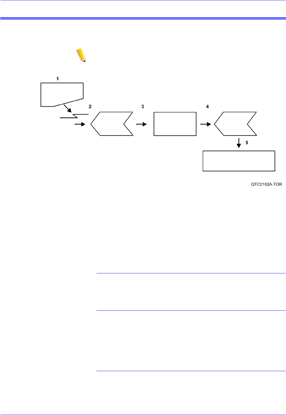
Figure 2-1. Job flow
1. Job
2. Input Queue
3. Decomposer
4. Output queue
5. Printer
Job
The job and the job ticket (if applicable) are received from the
network by one of the protocol gateways.
Input queue
The Job Pool Manager (JPM) process transfers the job into the
input queue. The virtual printer name and job attributes are
attached to the job. The job remains in the Input Queue until it can
be printed; for example, “held” and “faulted” jobs reside in the
input queue.
Decomposer
The Job Chooser reconciles the job attributes with the virtual
printer attributes. Once the job is ready for print, the Job Chooser
gives the job to the appropriate decomposer, PostScript or PCL.

DocuTech 128/155/180 HighLight Color Operator Guide 2-7
System components
Output queue
After decomposition, the job is stored in the output queue.
Printer
The marker transfers the job from the Output Queue to the printer.
After the job has successfully printed, it is removed from the
Output Queue and also from the Input Queue.
The printing process and job flow is different for PostScript, PCL,
TIFF, ASCII, PDF jobs (that is, non-LCDS or non-IPDS jobs) and
for LCDS or IPDS jobs.
PostScript, PCL,
TIFF, ASCII, LCDS,
IPDS, and PDF jobs
When the job is sent from the application for printing, a print data
file is created. This file becomes the job that is submitted to the
printer for printing. The print data file and the job request are
submitted to the selected queue. Jobs are processed by priority
within the designated queue once the job reaches the queue from
a given application.
Printer overview
The printer receives data from the print server and prints the
document according to the print options specified by the user. The
printer also stacks and collates the printed output.
The printer system is available in two configurations:
1. High volume printer with inverter feeder/stacker and up to
three feeder/stackers
2. Production publisher with either a 2-Tray, or 3-Tray interposer
and finisher
2-8 DocuTech 128/155/180 HighLight Color Operator Guide
System components
High volume printer
The components, special features, and configurations of the
Xerox DocuTech 128/155/180 HLC printer are shown in the
following figures.
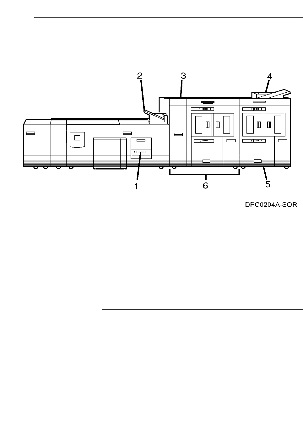
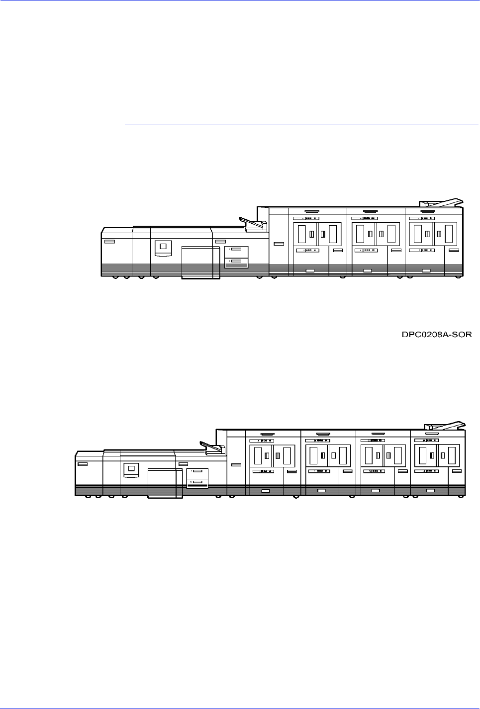
Figure 2-2. Printer with inverter feeder/stacker + feeder/
stacker (standard base configuration)
1. Feeder tray
2. Sample tray
3. Attention light
4. Purge tray
5. Feeder/stacker modules
6. Inverter feeder/stacker
Feeder/paper tray (High volume printer)
Multiple feeder/paper trays can be configured to feed paper for
jobs in the most effective manner. For example, the trays can
provide nonstop printing of a complex job that requires many
paper stocks, or only a few stocks, by using the trays continuous
loading capability. A different input tray can also be selected for
each copy of a specific page in a print job, for example, to provide
different paper colors for specific pages.
The printing system may have up to six feeder/paper trays: two
processor feeder trays and two to four high-capacity trays. Four
addressable input trays are standard with the system, and two
additional high-capacity trays are optional.

DocuTech 128/155/180 HighLight Color Operator Guide 2-9
System components
Processor feeder/
paper trays
Two processor feeder/paper trays (trays 1 and 2) are located in
the main part of the printer.
Trays 1 and 2 can handle paper sized from 8 by 10 inches / 203 by
254 mm to 9.02 by 14.02 inches / 230 by 356 mm.
Feeder/paper tray
capacity
Depending on your configuration, the feeder/paper trays have the
following capacities, based on 20 pound or 80 gsm (grams per
square meter) paper:
Tray 1: 1100 sheets
Tray 2: 600 sheets
Trays 3, 4, 5, and 6 (high-capacity trays): 2600 sheets each
An elevator moves each tray up or down when it is in use. In each
tray, a control panel consisting of a button, indicators, and paper
level displays controls the elevator tray and indicates its status.
Figure 2-3. Feeder/paper tray control panel
1. Ready to Open indicator
2. Please Wait indicator
3. Tray Unlock button
4. Paper Level indicators
Ready to Open
indicator
Glows green when the tray can be pulled out and paper can be
added to it.
Please Wait
indicator
Shows that the tray is in motion. This indicator is lit red when the
Tray Unlock button is pressed, while the tray is lowering, and while
the tray is rising. The indicator goes off when the tray elevator
reaches its destination.
Tray Unlock button Enables the tray to be opened.
• If the tray is in use when this button is pressed, the feed
selection switches to the backup tray if one has been
identified. Otherwise, printing stops.
• If the tray is in use and selected as a backup tray, pressing the
Tray Unlock button causes the tray elevator to lower and the
tray to be unavailable for auto switching.
• If the tray elevator is in the raised position and the tray is not in
use or selected as a backup tray, pressing this button causes
the elevator to lower with no effect on printing operations.
This button functions when the Please Wait indicator is off.

2-10 DocuTech 128/155/180 HighLight Color Operator Guide
System components
Paper Level
indicators
Display the approximate quantity of paper in the tray. Each display
shows paper by quarter reams up to one ream, and then by full
reams. The green indicator appears above its Paper Level
indicator.
Sample tray
NOTE: High volume printer configuration only
The sample tray, located on top of the printer, receives output
such as transparencies, sample sheets from printing jobs, prints
from system files such as forms, and waste sheets that cannot be
sent to the purge tray.
Monitor the sample tray and empty it when it contains 100 sheets.
The system does not notify you when the tray is full.
Attention light
An Attention light is mounted on top of the inverter module. This
light either blinks or modulates (alternately brightens and dims)
when the printer requires operator attention. The light has three
states:
Off: No printer problems exist that require attention.
Steady light: A situation exists that needs attention soon.
Flashing: The printer has stopped and requires your attention
immediately.
NOTE: When the Attention light starts flashing, an explanatory
message appears on the print server screen.
Purge tray
NOTE: High volume printer configuration only
The purge tray is located on top of the last feeder/stacker module.
Aborted sheets (for example, damaged sheets or sheets cleared
after a paper jam) are sent to this tray. The purge tray should be
emptied when it has received 100 sheets of paper.
The system does not notify you when the tray is full.
DocuTech 128/155/180 HighLight Color Operator Guide 2-11
System components
Inverter feeder/stacker
NOTE: High volume printer configuration only
Each output feeder/stacker has offsetting capability and a capacity
of 2500 sheets of 20 pound or 80 gsm paper.
This capacity does not apply to 11 by 17 inch and A3 papers.
Because of the additional weight these large sheets add to the
bins, each bin is restricted to hold only up to 1500 sheets of A3 or
11 by 17 inch papers, for safety reasons.
Figure 2-4. High capacity stackers (HCS)
The stackers can stack the printed output in the bin three ways:
1. Directly onto the bin platform.
2. Into a container that is set on top of the bin platform.
NOTE: The stacking capacity is approximately 100 to 150 sheets
less when stacking into a container.
3. Onto a pallet without a container (for paper sizes 11 by 17
inches or A3 only).
Using the stacking windows on the user interface, you can select
the level to which paper will be stacked in the HCS.
A stacking elevator maintains the paper at the proper level for
stacking and lowers the stack for unloading. An offset mechanism
offsets printed sets toward the front or back of the HCS bin.
The elevator platform lowers under the following conditions:
• The bin capacity has been reached.
• A selection to lower the platform is entered at the printer
control console or a user interface window.
• The job being printed reaches a designated unload boundary.
Each HCS bin has unlinked double doors to give you easy and
safe access for unloading output from the printer.
The elevator bin platform automatically rises when the doors are
closed after the stacker has been unloaded.
Bin control panels
on stackers
Each stacker bin has a control panel consisting of buttons and
indicators.

2-12 DocuTech 128/155/180 HighLight Color Operator Guide
System components
Figure 2-5. High capacity stacker bin control panel
1. Ready to Unload indicator on stacker bins
2. Please Wait indicator on stacker bins
3. Bin Unload button on stacker
4. In Use indicator on stacker bin
Ready to Unload
indicator on stacker
bins
When this indicator glows, you can remove printed sheets from
the stacker bin.
Please Wait
indicator on stacker
bins
When this indicator glows, the elevator is in motion. This indicator
turns off when the platform reaches its destination.
Bin Unload button
on stacker
Lowers the bin elevator.
• If the bin is in use when this button is pressed, the printed
pages begin stacking in the other stacker bin, if auto switching
has been enabled.
• If the bin is not in use, pressing this button does not affect
printing operations.
In Use indicator on
stacker bin
When this indicator glows, the bin has been made ready to receive
output.
Feeder/stacker modules
The feeder/stacker modules contain the high-capacity feeder trays
and the stacker bins. The printer may have up to four feeder/
stacker modules (including the inverter feeder/stacker), containing
feeder trays 3, 4, 5, and 6, and stacker bins A, B, C, and D. Each
module contains one high-capacity feeder tray and one high
capacity stacker bin.
High-capacity
feeders
The high-capacity feeder (HCF) trays are located in the bottom
half of the feeder/stacker modules. Each HCF tray can hold up to
2500 sheets of 20 pound or 80 gsm paper.
The high-capacity feeder trays can handle paper sized from 8 by
10 inches / 203 by 254 mm to 17 by 14.02 inches / 432 by 356
mm.
Unlike the processor feeder trays, the HCF trays have Paper
Level switches, which detect the position of the elevator to
determine the fullness of the tray.
DocuTech 128/155/180 HighLight Color Operator Guide 2-13
System components
High-capacity
stackers
The high-capacity stacker (HCS) bins are located in the top half of
the feeder/stacker modules, accessed through double doors.
Two high-capacity stacker bins are standard, with up to two
additional bins available as options (providing up to four bins
total). Each bin holds up to 2500 sheets of 20 pound or 80 gsm
paper.
More High volume printer configurations
In addition, the high volume printer is available with three or four
feeder/stacker modules.
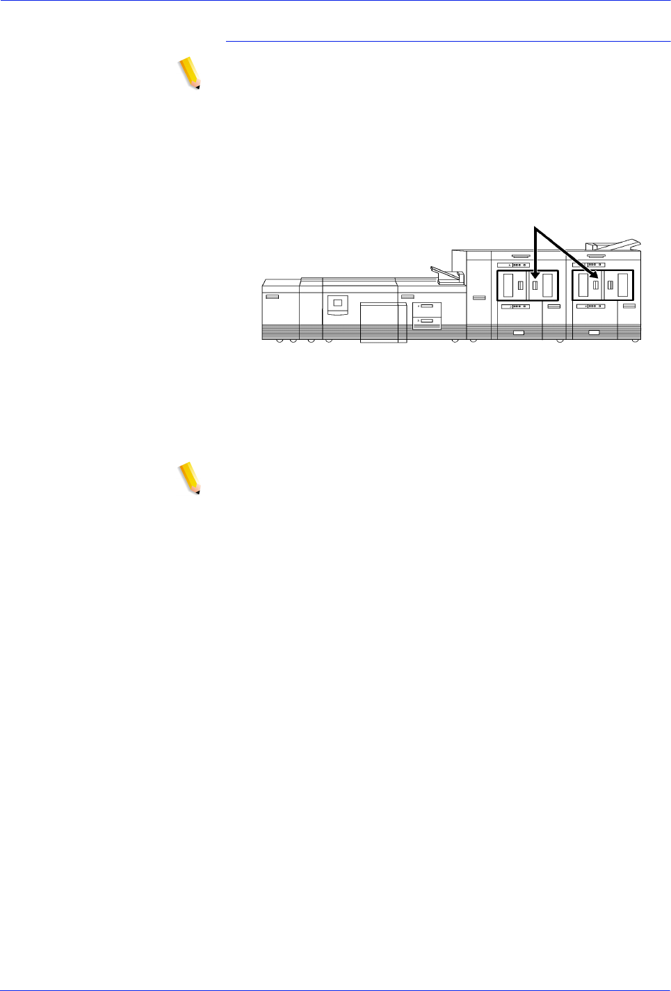
Figure 2-6. Printer with inverter feeder/stacker + feeder/
stacker + feeder/stacker
Figure 2-7. Printer with inverter feeder/stacker + feeder/
stacker + feeder/stacker + feeder/stacker
The illustrations above show a High volume printer configuration
with two feeder/stacker modules and a bypass transport, and a
printer with three feeder/stacker modules and a bypass transport.
With the bypass transport installed, the printer can support up to
three feeder/stacker modules, including the inverter feeder/
stacker.
2-14 DocuTech 128/155/180 HighLight Color Operator Guide
System components
Production publisher
The standard base components, special features, and
configurations of the Xerox DocuTech 180 HLC production
publisher printer are shown in the following figures.
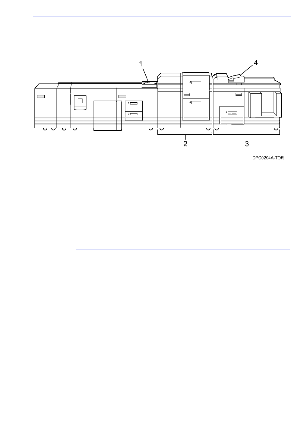
Figure 2-8. Production publisher: Printer + 2-Tray or 3-Tray
Interposer + stitcher/binder
1. Convenience tray
2. Interposer (2-Tray shown)
3. Finisher
4. Top tray
Convenience tray
The convenience tray provides an area to place documents or
other items while you are at the printer.
DocuTech 128/155/180 HighLight Color Operator Guide 2-15
System components
Interposer
NOTE: Production publisher configuration only.
The 2-Tray or 3-Tray Interposer module is located between the
print engine and the Finisher. The Interposer inserts blank or
preprinted sheets as required. Sheets fed from Tray 4 are not
imaged and feed directly into the finisher. Sheets from Tray 5 or
Tray 6 (Three-tray Interposer) can be set either to feed through
the Interposer via the print engine (passing through the Fuser) or
to deliver pre-printed stocks into the Finisher (post-Fuser).
Both models of Interposer have the ability to process ordered sets
fed from Tray 4. This makes it unnecessary to have additional
trays for each page type in a set. However, for jobs that include
pre-printed sheets that are not pre-collated or several jobs that
use ordered sets, Tray 5 and Tray 6 (3-Tray Interposer) can also
be set to feed directly into the Finisher (post-Fuser).
NOTE: Ordered sets can also be fed for imagining from Trays 1,
2, and 3.
Two-tray Interposer
(production
publisher only)
The 2-Tray Interposer allows applications to utilize up to five trays
to feed different paper stocks. Both trays may be used to feed pre-
printed stocks (bypassing the Fuser). If just Tray 4 is used for
post-Fuser feeding, four pick points are available for imaging
(passing through the fuser).
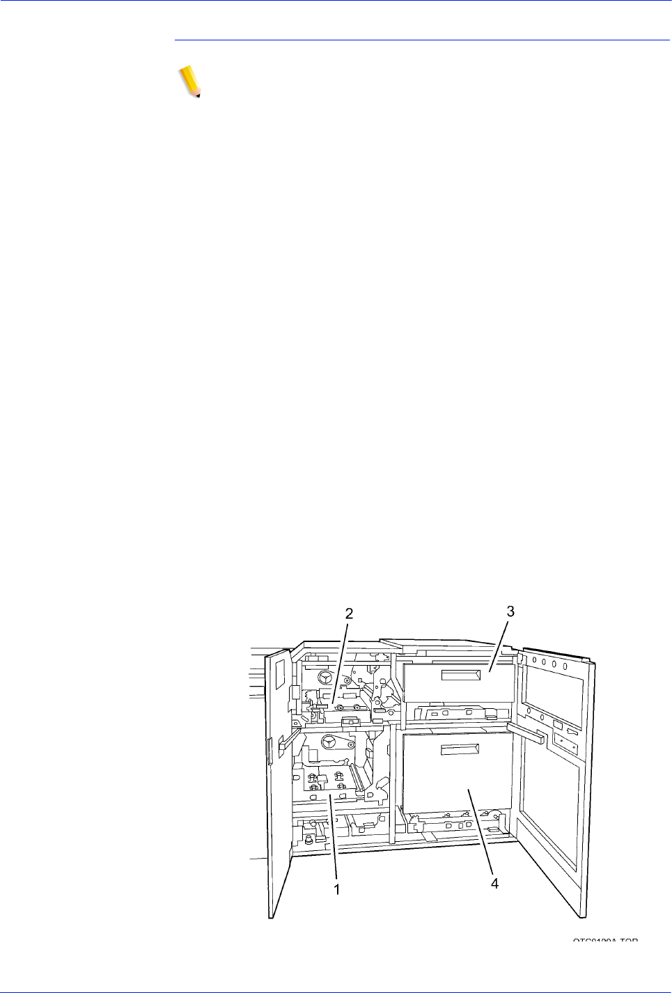
The following lists the 2-Tray interposer components
1. Paper transport (lower)
2. Paper transport (upper)
3. Inserter tray
4. Feeder/inserter tray
Figure 2-9. 2-Tray Interposer (production publisher only)
2-16 DocuTech 128/155/180 HighLight Color Operator Guide
System components
3-Tray Interposer
(production
publisher only)
The 3-Tray Interposer allows applications to utilize up to six trays
to feed different paper stocks. All three trays may be used to feed
pre-printed stocks (bypassing the Fuser). If just Tray 4 is used for
post-Fuser feeding, five pick points are available for imaging
(passing through the fuser).
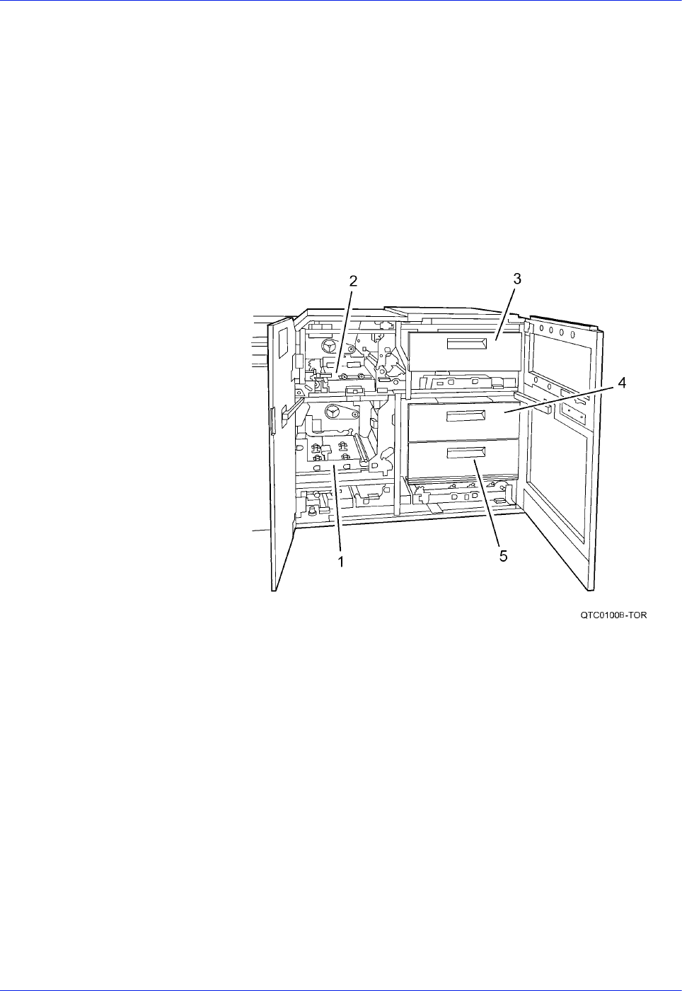
The following lists the 3-Tray interposer components
1. Paper transport (lower)
2. Paper transport (upper)
3. Inserter tray
4. Feeder / inserter tray (Tray 5)
5. Feeder / inserter tray (Tray 6)
Figure 2-10. 3-Tray Interposer (production publisher only)
DocuTech 128/155/180 HighLight Color Operator Guide 2-17
System components
Finisher
NOTE: Production publisher configuration only
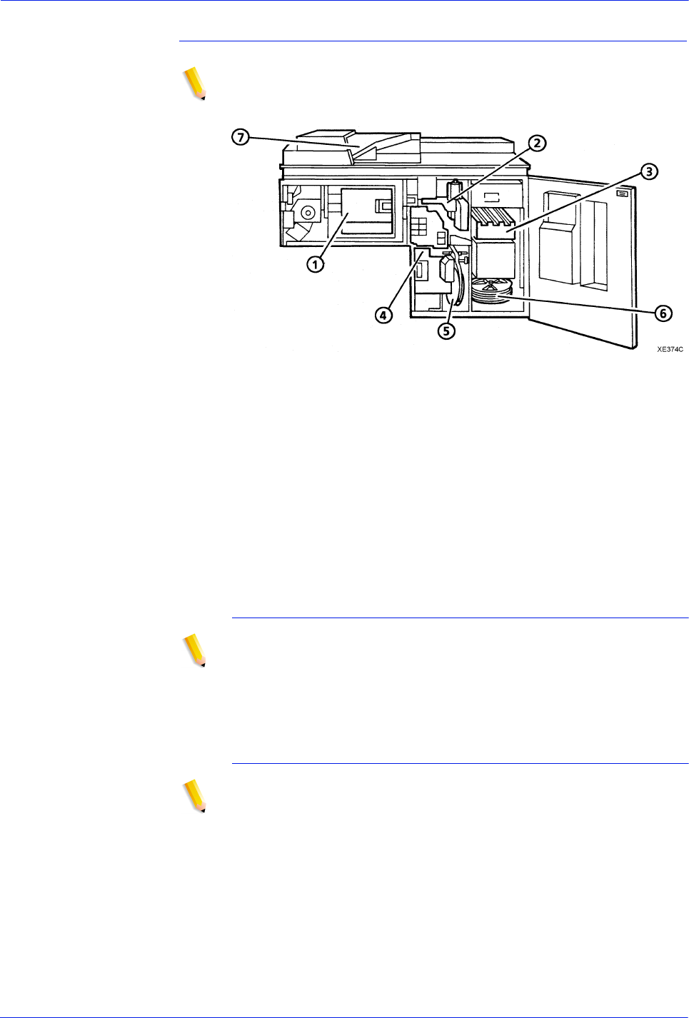
Figure 2-11. Finisher
In the finisher, prints can be collated, and stitched or bound, as
required for a job. The following lists the finisher components:
1. Bindexer
2. Stitcher
3. Stacker
4. Binder
5. Binder tape reel
6. Stitcher wire spools
7. Top tray
The bindexer
NOTE: Production publisher configuration only
The bindexer is a three-bin sorter that collates the pages of each
print set. As the pages of the print set are fed to the bindexer, the
bindexer moves up and down to collate them.
The stitcher
NOTE: Production publisher configuration only
When the job requires stitched output, the stitcher cuts and inserts
the wire stitches into each print set. The stitch length is related to
such factors as the number of pages in the print set and the print
stock weight. A single stitch can be placed in the portrait or
landscape print position. Dual stitching is available for landscape
and portrait prints. Stitch placement can be changed through the
FreeFlow Print Server software.
NOTE: For more information about setting stitch placement, refer
to the on-line help system.

2-18 DocuTech 128/155/180 HighLight Color Operator Guide
System components
The stacker
NOTE: Production publisher configuration only
The stacker collects unfinished or finished stitched or bound jobs.
When the stacker is full, or the job is completed, the stacker door
opens and the stacker drawer that holds the prints comes out.
After the stacker drawer is unloaded, the system retracts the
drawer and closes the door. The stacker also can be unloaded
during the printing cycle to check the quality of the print sets by
changing the printer options.
NOTE: For more information, refer to the on-line help system.
The binder
NOTE: Production publisher configuration only
When a job requires bound output, a length of pre-glued paper
tape is placed on a heated surface called the binder platen. The
system aligns the pages of each print set before placing the set on
the tape. Binder flappers then press the tape to the sides of the
set. The combination of the heat in the binder and the pressure of
the flappers glues the tape to the set.
NOTE: For information about adjusting the binder tape
registration and the binder tape length, refer to the on-line help
system.
The top tray
NOTE: Production publisher configuration only
Prints are delivered to the top tray because the prints are
oversized or because the top tray was selected at the print server.
Bypass transport
Function of the
bypass transport
The bypass transport moves paper from the printer to a third-party
finisher such as a stitcher, booklet maker, tape binder, and so on.
By making selections on the user interface windows, you can
program the printer to send output to the bypass transport, which
feeds the output to the finishing equipment.
Paper stocks
supported on
bypass transport
The bypass transport accepts all paper stocks on which the printer
can print, and it accommodates simplex and duplex printing.
DFA support The bypass transport meets the Xerox Document Feeding and
Finishing Architecture (DFA) specifications. The system software
supports DFA. However, in order for the bypass transport to
function correctly, you need to set up finishing personality profiles
to identify your finishing device to the printing system. (The
customer support representative for your finishing device can give

DocuTech 128/155/180 HighLight Color Operator Guide 2-19
System components
you the information you need to create a personality profile for
your third-party finishing device.)
For information on marketing partners that provide solutions for
support and interface with finishers, contact your local Xerox sales
representative.
Bypass transport on the production publisher
Depending on the finisher configuration, the bypass transport is
located inside the finisher module on the Production publisher
configuration. Bypass transport function is the same as the
external bypass transport module.
NOTE: The Production publisher finisher is available with or
without the bypass transport.
Bypass transport on the High volume printer
Connected to the last feeder/stacker module. The bypass
transport option enables third-party finishing devices to interface
directly with the printing system. The bypass transport allows you
to customize your printer for increased efficiency and specialized
applications involving finishing.
NOTE: Systems configured with the external bypass transport
can have a maximum of two (2) feeder/stacker modules. See
figure 2-13.
7 by 10 inch enablement kit
The 7 by 10 inch enablement kit allows the printing system to print
on 7 by 10 inch/178 by 254 mm paper size, with throughput speed
of up to 206 PPM.
Paper paths
The paper path is the route that materials (paper, transparencies,
labels, and so on) follow through the printer from the feeder trays
to the output bins or finisher.
2-20 DocuTech 128/155/180 HighLight Color Operator Guide
System components
High volume printer paper path
The following figure shows the path the paper takes through the
high volume printer.
Figure 2-12. Route of paper through the high volume printer
1. Processor feeder tray 1
2. Processor feeder tray 2
3. High-capacity feeder tray 3
a. Side 1 of sheet leaving feeder tray
b. Drilled holes (on right edge)
c. Origin 0,0: portrait orientation

DocuTech 128/155/180 HighLight Color Operator Guide 2-21
System components
4. High-capacity feeder tray 4
a. Side 1 of sheet leaving feeder tray
b. Drilled holes (on right edge)
c. Origin 0,0: portrait orientation
5. Paper inverter
6. Duplex inverter
7. Sample tray
8. High-capacity stacker bin A
a. Side 2 of sheet stacked in bin
b. Drilled holes (on left edge)
c. Origin 0,0: portrait orientation
9. High-capacity stacker bin B
a. Side 2 of sheet stacked in bin
b. Drilled holes (on left edge)
c. Origin 0,0: portrait orientation
10. Purge tray
11. Bypass transport
a. Side 2 of sheet passing through bypass transport
b. Drilled holes (on left edge)
c. Origin 0,0: portrait orientation
2-22 DocuTech 128/155/180 HighLight Color Operator Guide
System components
Production publisher paper path
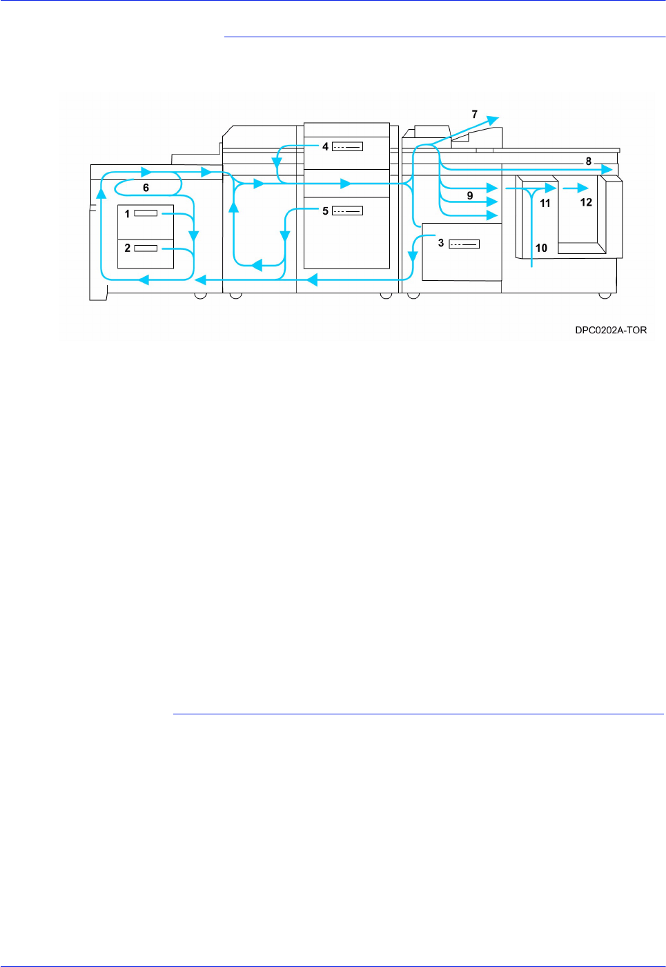
The following figure shows the path the paper takes through the
production publisher.
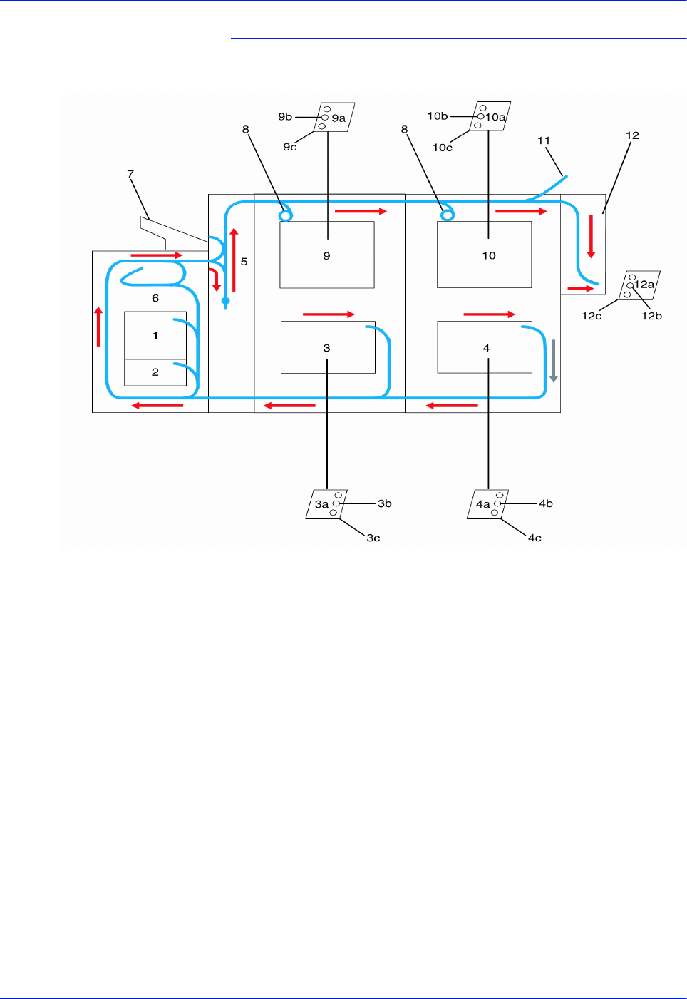
Figure 2-13. Route of paper through the production publisher
1. Processor feeder tray 1
2. Processor feeder tray 2
3. High capacity paper tray
4. Paper inserter tray
5. High capacity paper tray (Two-tray Interposer shown)
6. Duplex inverter
7. Purge tray
8. Bypass transport
9. Bindexer area
10. Bind area
11. Stitch area
12. Stacker area
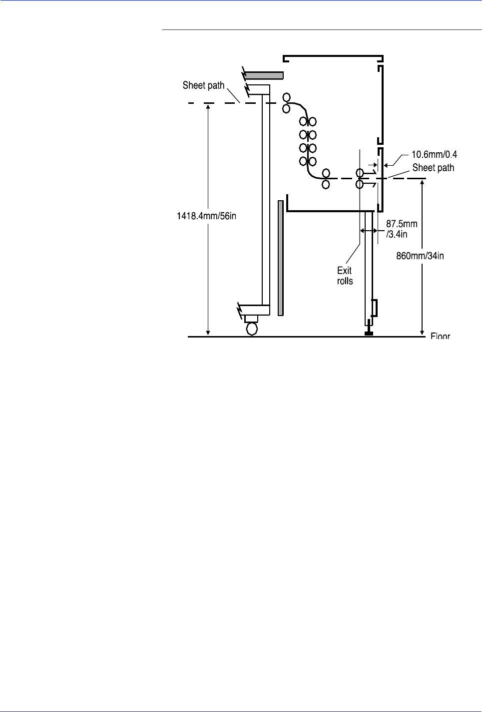
Bypass transport paper path
The following figures show the paper path through the bypass
transport, viewed from the front of the printer.
DocuTech 128/155/180 HighLight Color Operator Guide 2-23
System components
High volume printer bypass transport paper path
Figure 2-14. Bypass transport paper path (high volume
printer configuration shown)
1. Sheet path
2. Exit rollers
3. Floor

2-24 DocuTech 128/155/180 HighLight Color Operator Guide
System components
The System
System Hardware
The basic hardware components of the DocuTech 128/155/180
HLC systems are the FreeFlow Print Server and the printer.
The FreeFlow Print Server
The FreeFlow Print Server is the connection between you and the
system. You communicate through the FreeFlow Print Server
software by selecting and managing the jobs displayed on the
screen and sending them to the printer for production. The system
also communicates messages and instructions to you on the Print
Server interface screen.
The print server consists of a specially-configured workstation and
uses proprietary Xerox hardware, firmware, and software.
Specifications can be obtained from your Xerox customer
representative or by accessing the Setup, System Configuration
feature on the FreeFlow Print Server user interface.
NOTE: Print server hardware configurations are subject to
change to keep up with advances in technology.
Print Server overview
The print server receives LCDS, IPDS, PostScript, and PCL data
streams from a mainframe host or a workstation client, processes
the data, and sends it to the printer. The print server also provides
the printer with print data and commands and receives status
information from the printer.
The print server consists of a workstation, which is run by the Sun
Solaris Operating environment. Also resident on the print server is
software which manages all printing, diagnostic, and
administrative functions on the printing system.
The FreeFlow Print Server software includes a full-color graphical
user interface, which enables you to interact with the printing
system to set up and configure the system, to set up and
implement system options, to run print jobs, etc.
Online Help (menus and buttons) provides access to online help
that contains information when requested.

DocuTech 128/155/180 HighLight Color Operator Guide 2-25
System components
Accessing FreeFlow Remote Print Server remotely
FreeFlow Remote Print Server, a remote graphical user interface
(GUI), is available for installation from a CD. FreeFlow Remote
Print Server allows you to manage your FreeFlow Print Server-
based printers from a single PC or Sun workstation. You may set
your preferences from the remote client to disable or enable some
or all connections.
FreeFlow Remote Print Server allows you to configure the printers
that you want to manage, and provides real time status of the
printers. You may switch between the printers that you are
managing, but you can display only one printer GUI at a time.
The remote client GUI looks and functions the same as the local
FreeFlow Print Server GUI on the print server.
Moving the print server
To ensure consistent performance and avoid any damage to
equipment, follow these rules for placing the components of the
print server.
Do:
Use the print server stand that comes with your printing system
equipment.
Keep the processor in an upright, vertical position.
Allow at least 6 inches / 152 mm of unobstructed space at the front
and rear of the processor, so the fan and vents are not blocked.
CAUTION: Do not place the monitor on top of the processor. Do
not block any fan or vent on the front, sides, or rear of the
processor.
Do not:
Do not place the monitor on top of the processor.
Do not allow any piece of equipment to blow warm air into the air
intake vents of the processor.
Do not place the processor on its side, or in any other position but
the upright, vertical position achieved by using the print server
stand.
Do not place the processor or monitor on top of the printer.
Tape drives overview
The DocuTech 128/155/180 HLC supports several types of tape
drives that may be used to load resources (forms, fonts, etc.) or to
submit offline LCDS print jobs.
A 26-track cartridge tape drive can be used only to import
resources to the system disk. A 9-track or 36-track tape drive can
be used to submit print jobs to the printer or to load resources.
2-26 DocuTech 128/155/180 HighLight Color Operator Guide
System components
The FreeFlow Print Server Tape Client software enables
transmission of data from a cartridge or open reel tape to the
FreeFlow Print Server via the Socket gateway.
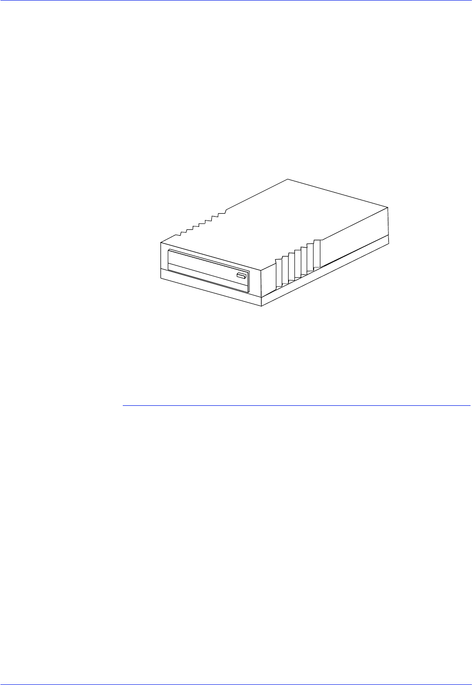
The 4 GB external SCSI quarter inch cartridge (QIC) tape drive is
an external device. The cartridge tape drive connects to the print
server through the SCSI port on the processor back panel.
Like the diskette and DVD drives, this tape drive is not an input
source for print jobs or for any other data or application. You can
use it to load resource files, and the service representative uses it
to load system maintenance files or to save diagnostic
information.
Figure 2-15. 26-track cartridge tape drive
36-track cartridge
tape drive
An 18/36-track cartridge tape drive is an option. You can use this
drive to load resources and to submit offline LCDS print jobs.
Peripheral cabinet (9-track and 18/36-track tape drives)
Some Xerox customers may already have a peripheral cabinet
that houses a 9-track magnetic and an 18/36-track cartridge tape
drive. If a peripheral cabinet has either of the following 18-track
tape drives, they are not supported:
STK 4220 MOD 1 tape drive
STK 4220 MOD 2 tape drive
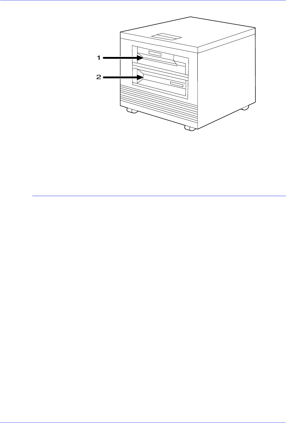
DocuTech 128/155/180 HighLight Color Operator Guide 2-27
System components
Figure 2-16. Peripheral cabinet
1. 9-track magnetic tape drive
2. 18/36-track cartridge tape drive
Paper sizing and print speed
The printer paper trays have edge guide sensors that detect paper
length and width. The system selects correct paper trays for the
print job based on the paper parameters, such as size, weight,
color, or coating, specified in the job as follows:
• If an exact match is found, the print job continues.
• If an exact match is not found, the operator can specify in the
job for the printer to do one of the following:
– Stop printing the job and print an error sheet.
– Print the data on an oversized sheet.
If you encounter any problems related to paper sizing, contact
your lead operator or Xerox service representative.

2-28 DocuTech 128/155/180 HighLight Color Operator Guide
System components
Long and short edge
feeding
To feed through the printer, the leading edge of the paper must be
at least 10 inches long. Therefore, the following standard sizes of
paper must be loaded so that sheets feed long edge first:
• 7 by 10 inch
•B5
•A4
•US letter
•B4
•US legal
The following papers, which have long edges greater than 14.33
inches / 364 mm must feed short edge first:
•A3
• US ledger or US tabloid
NOTE: JIS B4 can be fed either long edge or short edge first.

DocuTech 128/155/180 HighLight Color Operator Guide 3-1
3 Routine maintenance
This section describes the routine activities you perform to
maintain the reliability and productivity of your printer.
Cleaning and maintenance overview
Some printer components need to be cleaned periodically to help
keep the system operating reliably, and to ensure that the print
quality is consistent.
When supplies get low, an indicator will appear in the FreeFlow
Print Server window on the print server. You should respond to the
fault or message as soon as possible to avoid a printer shut down.
The system provides dry ink to the printer from a bottle located in
the printer. When the screen displays an “empty” message, a full
dry ink bottle must be installed.
Waste dry ink empties into a container located at the side of the
printer, under the toner filter. When this container becomes full, it
must be replaced.
Fuser lubricant must be added to the fuser reservoir in the printer
when a “low” message on the screen directs you to do so. Fill the
fuser reservoir at this time or the printer shuts down.
For information on cleaning the processor sensors, the reflecting
surfaces, and the finisher sensors, refer to the Problem solving
chapter.
NOTE: The DocuTech HLC fuser oil is a specially blended fuser
shield specifically for the DocuTech HLC systems.
CAUTION: The DocuTech HLC fuser shield must not be used in
any other Xerox product.
CAUTION: Use only the DocuTech HLC fuser shield in the
DocuTech HLC systems.
Necessary Precautions
For your own safety and to protect the system, it is important to
take the following precautions whenever you perform cleaning
and replacement tasks.
• Use only the cleaning and replacement supplies that are
approved or recommended by Xerox. If you use other

3-2 DocuTech 128/155/180 HighLight Color Operator Guide
Routine maintenance
supplies, you may damage the system.
• Keep supplies in stock as listed in the Service and supplies
chapter.
• Whenever you use or remove a part from the system, handle
the part carefully. Note any informative labels on the system.
• Keep atomized and aerosol sprays away from the system.
• Pour cleaning liquids onto a cloth. Do not pour or spray liquids
directly onto system parts.
• Before reinstalling a system part that has been cleaned with a
liquid, ensure that the part is dry.
• Always use a drop cloth when replacing the dry ink bottle,
highlight color container, or when adding fuser shield.
• Some parts of the system, such as the fuser, get hot during
operation. To ensure that you do not burn yourself, be careful
when working around these parts.
WARNING: The fuser can reach a temperature of approximately
425°F (218°C). Exercise care to prevent burns when working near
this area.
Finisher precaution
NOTE: Production publisher configuration only
The system uses stitcher wire from two spools located below the
stacker. Stitcher spool A is used for portrait, top corner stitches.
When stitcher spool A is empty, it must be replaced with a new
stitcher spool. Stitcher spool B is used for portrait dual stitches and
landscape stitches.
To replace stitcher spool B, contact the Customer Support Center;
refer to the section, “Calling for assistance”, in this guide.
To replace stitcher spool A, refer to the section, “Replacing the
stitcher spool A”, in this guide.
The system applies binder tape from a reel mounted in the binder
drawer in the finisher. You will need to replace the binder tape
periodically.
WARNING: All areas of the binder drawer, including the binder
tape, are approximately 425°F (218°C) and may cause a serious
burn to the operator. If the binder has been in a "Ready" condition,
allow the binder to cool for at least one hour before attempting to
clean the binder.
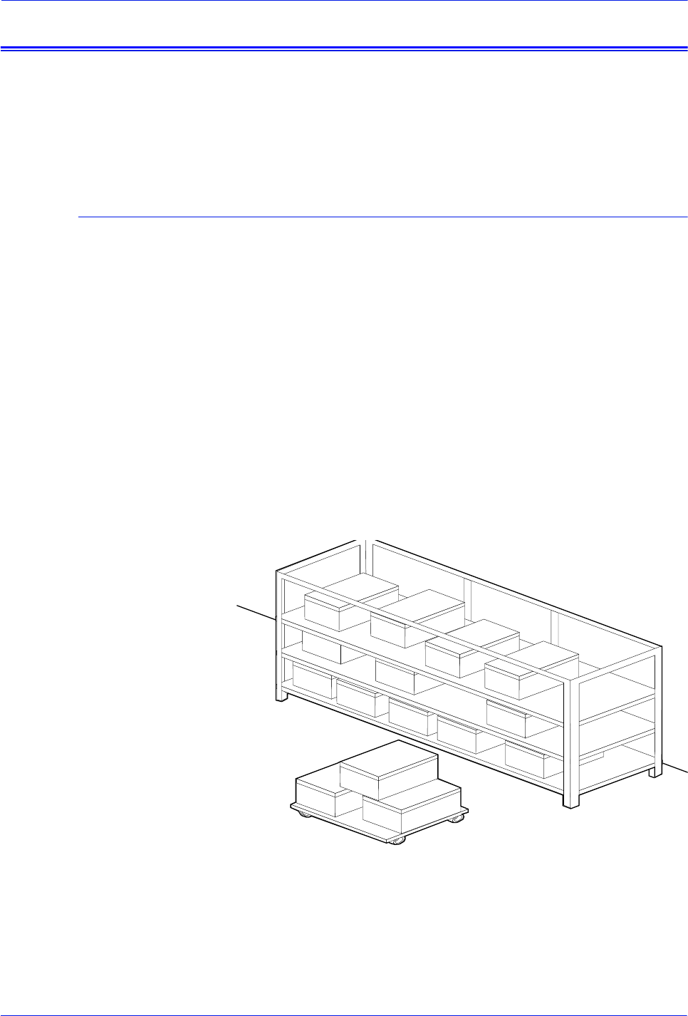
DocuTech 128/155/180 HighLight Color Operator Guide 3-3
Routine maintenance
Paper
You can add the same kind of paper to a tray when the supply is
low without stopping the printer. You must have the same paper or
stock loaded in two trays for the system to continue printing while
you are loading the other tray.
Storing paper
It is important to store paper correctly. Temperature and humidity
affect the way your printer processes paper.
Store paper in the cartons it came in. To reduce the possibility of
moisture absorption, always place cartons on a wooden pallet or
store them in a cabinet off the floor.
After removing the paper from its carton, always store it:
• In its wrapper
• On a flat surface
• In a closed cabinet
• In a cool, dry area
• In 68 to 76o F. / 20 to 24.4o C.
• In 35% to 55% humidity
Figure 3-1 Storing paper correctly

3-4 DocuTech 128/155/180 HighLight Color Operator Guide
Routine maintenance
Figure 3-2 Recommended temperature and humidity for
paper storage
Conditioning paper
Because temperature and humidity affect paper performance in
the printer, you need to condition paper before using it. To
condition paper, store it for a specified length of time in the same
type of environment as your printer.
The length of time you should condition your paper depends on
the amount of paper and the difference between the storage and
operating temperatures.
Use the following chart to determine the number of hours needed
to condition stacked cartons of paper.
NOTE: The numbers in the top two rows indicate the temperature
difference between the storage area and the operating
environment, not actual room temperatures.

DocuTech 128/155/180 HighLight Color Operator Guide 3-5
Routine maintenance
Table 3-1. Paper conditioning
Example: If you want to move ten cartons of paper from a storage
area with a temperature of 90o F. to an operating area with a
temperature of 70o F. (a 20 o difference), you should do so at least
18 hours before using the paper.
Paper curl
Before the manufacturer cuts paper into sheets, it is stored on
large rolls. After it is cut and packaged, it retains some of the curl
from the rollers.
Although it is unnecessary to load paper with the curl facing up or
down, best results occur when you are consistent. For example, if
you open paper with the wrapper seam up, always load it in the
tray that way.
Temperature difference between storage and
operating areas
Centigrade 10o15o20o25o30o40o50o
Fahrenheit 5.5o8.5o11o13o17o22o26o
Cartons Hours needed to condition the paper
1 4 8 1114172434
5 5 9 1215182535
10 8 141822273851
20 11 16 23 28 35 48 67
40 14 19 26 32 38 54 75
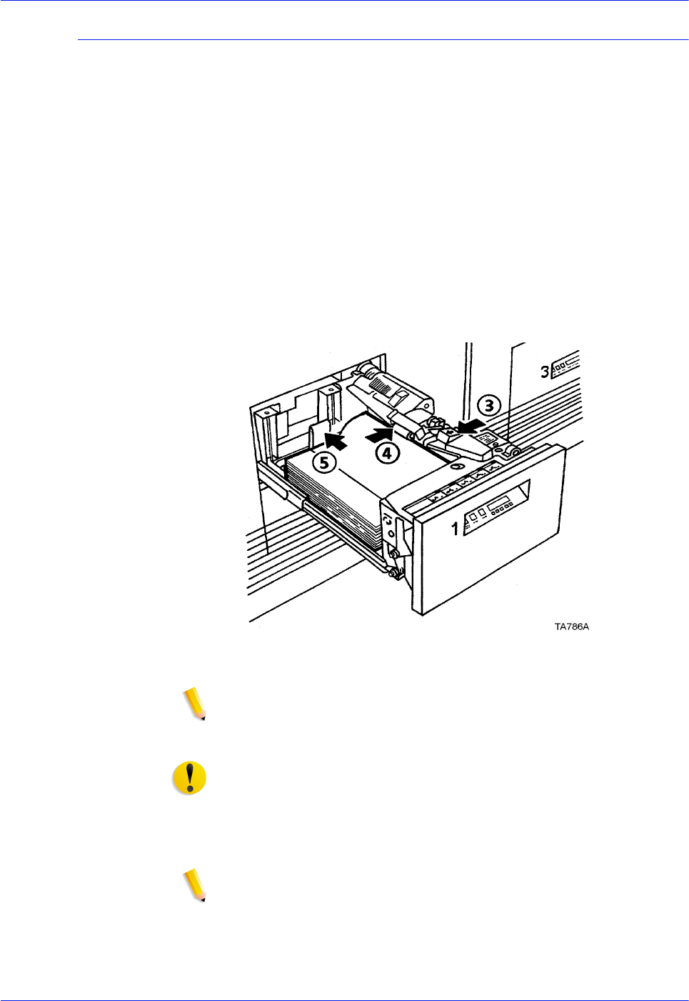
3-6 DocuTech 128/155/180 HighLight Color Operator Guide
Routine maintenance
Adding paper to tray 1 or 2
The following steps must be performed to add paper to tray 1 or 2.
1. Press the Tray unlock button on the front of the tray. Wait for
the red "Please wait" light to go off.
2. When the green "Ready to open" light comes on, pull the tray
out until it stops.
Steps 3 through 5 of loading paper into tray 1 or 2 are
illustrated in Figure 3-3.
3. Press the green release tab.
4. Lift the metal handle on the feed belt and remove any paper
under the belt.
5. Move the rear guide to the back of the tray.
Figure 3-3 Preparing the paper tray
NOTE: To load the paper correctly, refer to the label located
on the inside panel at the front of the paper tray. Remove any
damaged sheets from the top of the stack.
CAUTION: Do not load the paper above the red line. A jam could
occur if too much paper is loaded in the tray.
6. Load the required paper into the paper tray. Load paper with
the curl side facing down. Load Xerox paper with the package
wrapper seam side facing up.
NOTE: When loading drilled paper, be sure to fan the edge
where the holes are located.
7. Position the stack against the front right corner of the tray, as
shown in Figure 3-4. This is indicated by the green arrow on
the bottom of the tray.
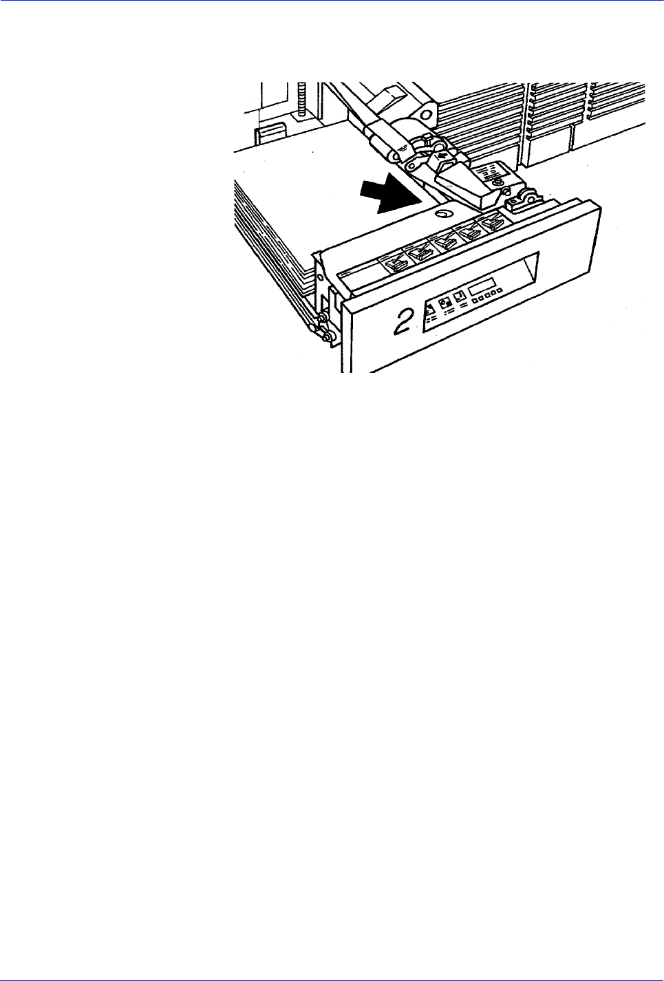
DocuTech 128/155/180 HighLight Color Operator Guide 3-7
Routine maintenance
For stock outside the recommended limits, refer to the
"Technical information" chapter in this guide.
Figure 3-4 Positioning the stack
8. Move the rear guide forward until it touches the edge of the
stack.
9. Lower the feed belt.
10. Close the tray slowly, but firmly, until it latches.

3-8 DocuTech 128/155/180 HighLight Color Operator Guide
Routine maintenance
Adding paper to trays 3, 4, 5, or 6
Paper Tray 3 is used to supply the largest volume of paper
required for your jobs. Trays 3, 5 and 6 (3-tray Interposer only) can
also be used to supply oversized paper for special jobs. Paper in
Tray 4 is only used for post-process insertion.
These trays lower one ream at a time as paper is added. More
than one ream can be loaded by pressing the Tray unlock button
again after the tray is fully opened.
Follow the described steps in the previous section to add paper to
Trays 3, 4, 5 or 6.
Using the custom transfer assist blade
The custom transfer assist blade in the printer assures good print
quality for your jobs. A kit is available allowing you to customize
the transfer assist blade for use with nonstandard paper sizes.
You cannot use the custom transfer assist blade for print jobs that
use more than one paper size. In addition, the following paper
lengths cannot use the blade:
In U.S. markets
– 11.1 to 11.4 inches/282 to 290 mm
– 11.8 to 12.1 inches/300 to 307 mm
– 13 to 13.5 inches/330 to 343 mm
In non-U.S. markets
– 11.1 inches to 11.4 inches/282 to 290 mm
– 11.8 inches to 12.1 inches/300 to 307 mm
NOTE: With these paper sizes, transfer efficiency may be
reduced.
CAUTION: To avoid damage to the photoreceptor, you must set
the tray size with the transfer assist blade.
Installing the
custom transfer
assist blade
The custom transfer assist blade comes in a package containing
detailed instructions. Be sure you follow the instructions carefully.
CAUTION: To prevent damage to the system, have your service
representative show you the procedure before you attempt to
customize and install a transfer assist blade for the first time.
Setting tray size with
the custom transfer
assist blade
When you are using the custom transfer assist blade, you must
set the tray length. Use the following two tables to determine the
tray length setting to use.
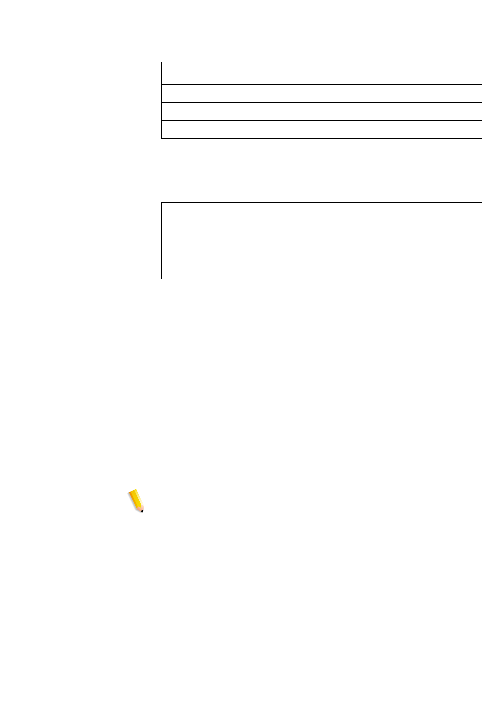
DocuTech 128/155/180 HighLight Color Operator Guide 3-9
Routine maintenance
Table 3-2. Tray length settings for custom transfer assist
blades (U.S. markets)
Table 3-3. Try length settings fro custom transfer assist
blades (Non-U.S. markets)
Adjusting for paper curl
Each sheet of paper has a natural curve called the curl. Storing or
using the paper under humid conditions may increase the curl.
When too much curl causes paper handling problems, adjust the
decurler in the processor. The decurler flattens the paper after
fusing.
Measuring the paper curl
1. Program and print five 1-sided, 8.5 x 11 inch (216 x 279 mm)
sheets to the top tray.
NOTE: Keep the image toward you, as shown in Figure 3-5.
2. Measure the amount of curl in the prints by holding the five
prints in the top center of the short edge.
Paper Size Set Paper Size
11.5 to 11.7 inches/292 to 297 mm 11.7 inches/297 mm
12.1 to 12.9 inches/307 to 328 mm 13 inches/330 mm
13 to 13.9 inches/330 to 353 mm 14 inches/356 mm
Paper Size Set Paper Size
10 to 10.9 inches/254 to 277 mm 11 inches/279 mm
11.5 to 11.6 inches/292 to 294 mm 11.7 inches/3297 mm
12.1 to 12.9 inches/307 to 328 mm 13 inches/330 mm
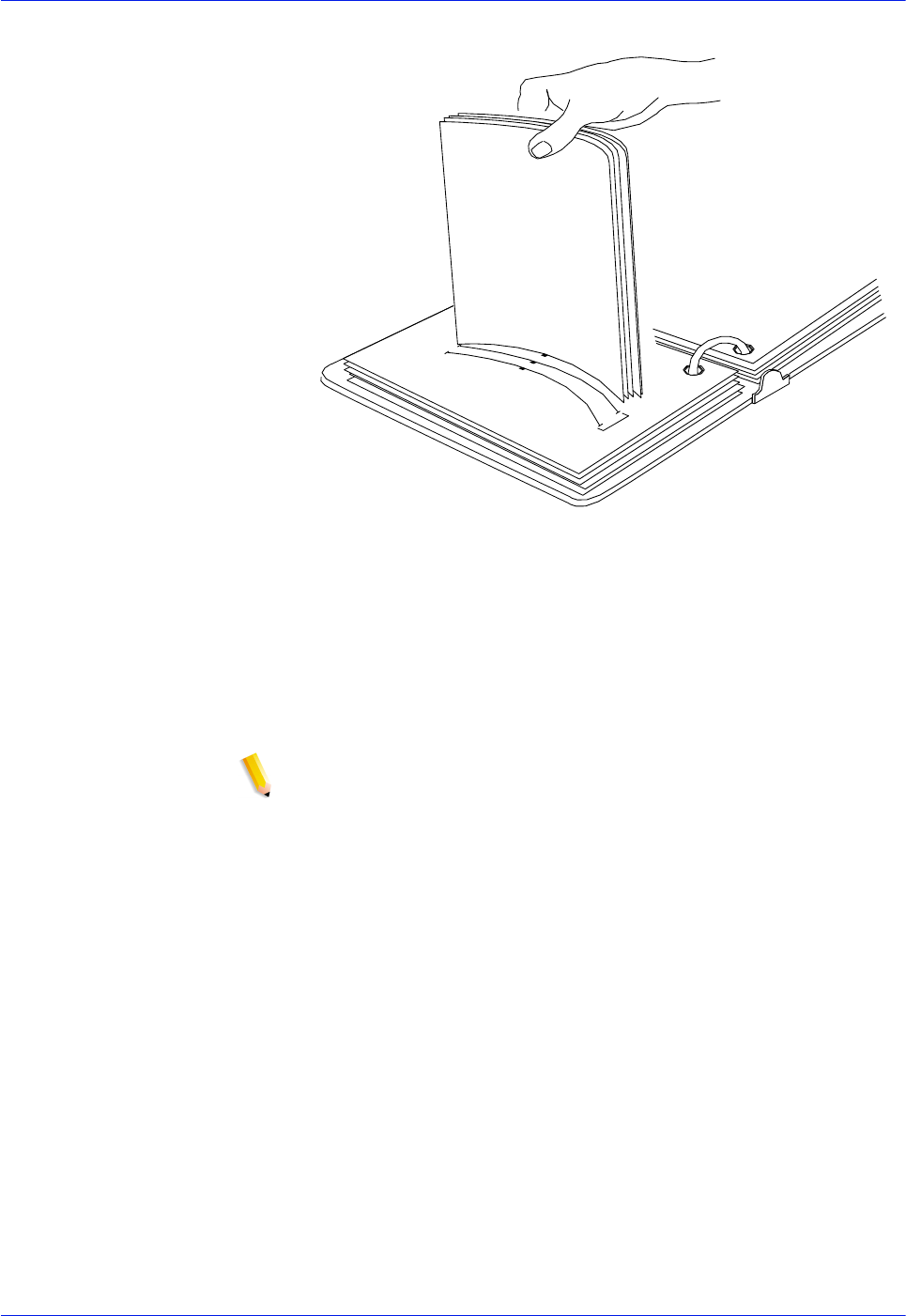
3-10 DocuTech 128/155/180 HighLight Color Operator Guide
Routine maintenance
Figure 3-5 Measuring the paper curl
3. Place the bottom edge of the prints over the paper curl
measurement chart in this guide.
• If the print curl on the printed paper measures between +1
and - 2, do not change the decurler setting.
• If the curl is between +2 and +3, or - 3 and - 4, refer to the
procedure, "Adjusting the decurler lever," in this section.
NOTE: Superior performance for greater than substance 32
(120 g/m2) can be achieved between +1 and -1 curl.
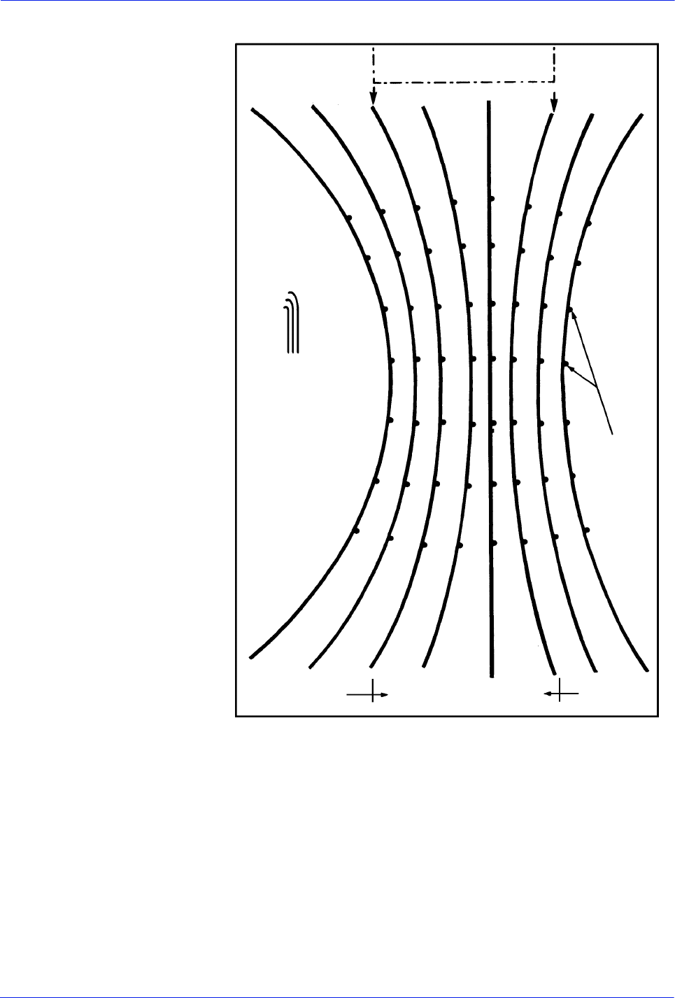
DocuTech 128/155/180 HighLight Color Operator Guide 3-11
Routine maintenance
Figure 3-6 Measuring the paper curl
Note: Corners of
the sheets of paper
should not exceed
curl shown in this
chart.
Image
Move green
decurler lever
Move green
decurler lever
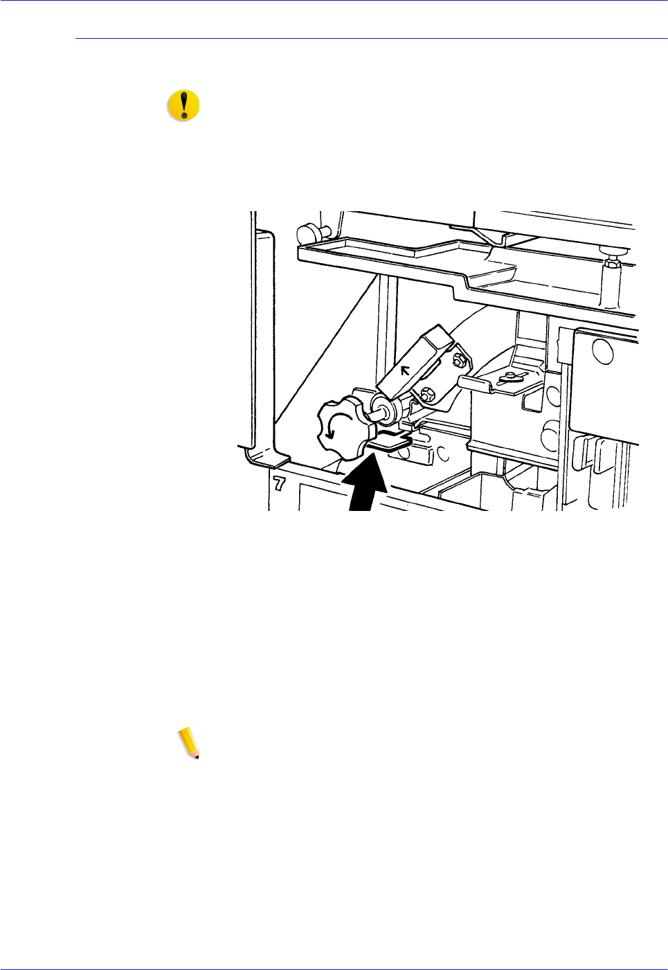
3-12 DocuTech 128/155/180 HighLight Color Operator Guide
Routine maintenance
Adjusting the decurler lever
Perform the following steps to adjust the decurler lever.
CAUTION: Do not use any paper that is not suitable for system
use.
1. Open the right door of the processor.
2. Locate the decurler lever in area 7 of the paper path, as shown
in the figure below.
Figure 3-7 Locating the decurler lever
3. If the print curl is +2 or more, move the green decurler lever to
the right.
4. If the print curl is -3 or more, move the green decurler lever to
the left.
5. If the decurler adjustment does not eliminate the paper curl
problem, or for other curl problems, turn the stack of paper
over in the paper tray.
6. If there is still a curl problem, perform steps 1 to 4 again.
NOTE: A final solution to the curl problem may be to load a
new ream of paper.
7. Close the processor door.

DocuTech 128/155/180 HighLight Color Operator Guide 3-13
Routine maintenance
Maintaining the printer
A screen message is displayed when it is necessary to replace
system supplies. To ensure that the system runs efficiently,
replace the supplies as soon as possible.
Replacing the black dry ink bottle
When directed by a screen message, replace the black dry ink
bottle. If the bottle is not replaced, the printer will eventually stop,
and it will not operate until a new bottle is installed.
CAUTION: To prevent dry ink spills, remove the bottle only when
directed to do so by a message on the screen.
CAUTION: Do not use warm or hot water, or general cleaning
solvents to remove dry ink from your skin or clothing. The heat or
solvent will set the dry ink and make it difficult to remove.
CAUTION: If any dry ink should get on your clothes, brushing
with a dry paper towel or a stiff-bristled brush may remove the ink.
If not, launder your clothes with detergent and cold water. Tell a
commercial dry cleaner that the spot is dry ink or "toner" so that
they will not use a solvent that will set the dry ink stain.
Replace the black dry ink bottle
The following steps must be performed to replace the black dry ink
bottle.
1. Open the front processor access door and locate the black dry
ink bottle at the left side of the processor.
2. Place a drop cloth on the floor under the dry ink bottle area.
3. Remove the empty bottle by grasping the bottle handle. With a
slow, firm motion, pull the bottle from the bottle guide.
a. Pull the empty dry ink bottle out until it stops.
b. Move the green handle to the unlatched position.
c. Remove the empty bottle and discard it.
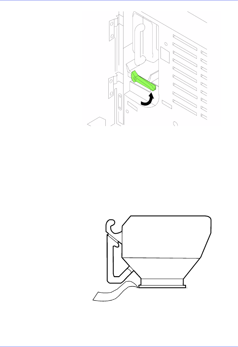
3-14 DocuTech 128/155/180 HighLight Color Operator Guide
Routine maintenance
Figure 3-8 Removing the empty bottle
4. To insert a new bottle, place the bottle on the edge of the bottle
guide.
a. With a slow, firm motion push the bottle into the dispense
position over the hopper.
b. Turn a new bottle of dry ink upside down and shake the
bottle thoroughly to loosen the contents. Insert the full
bottle until it stops.
Figure 3-9 Inserting and latching the bottle
c. Slide the full bottle all the way into the system.
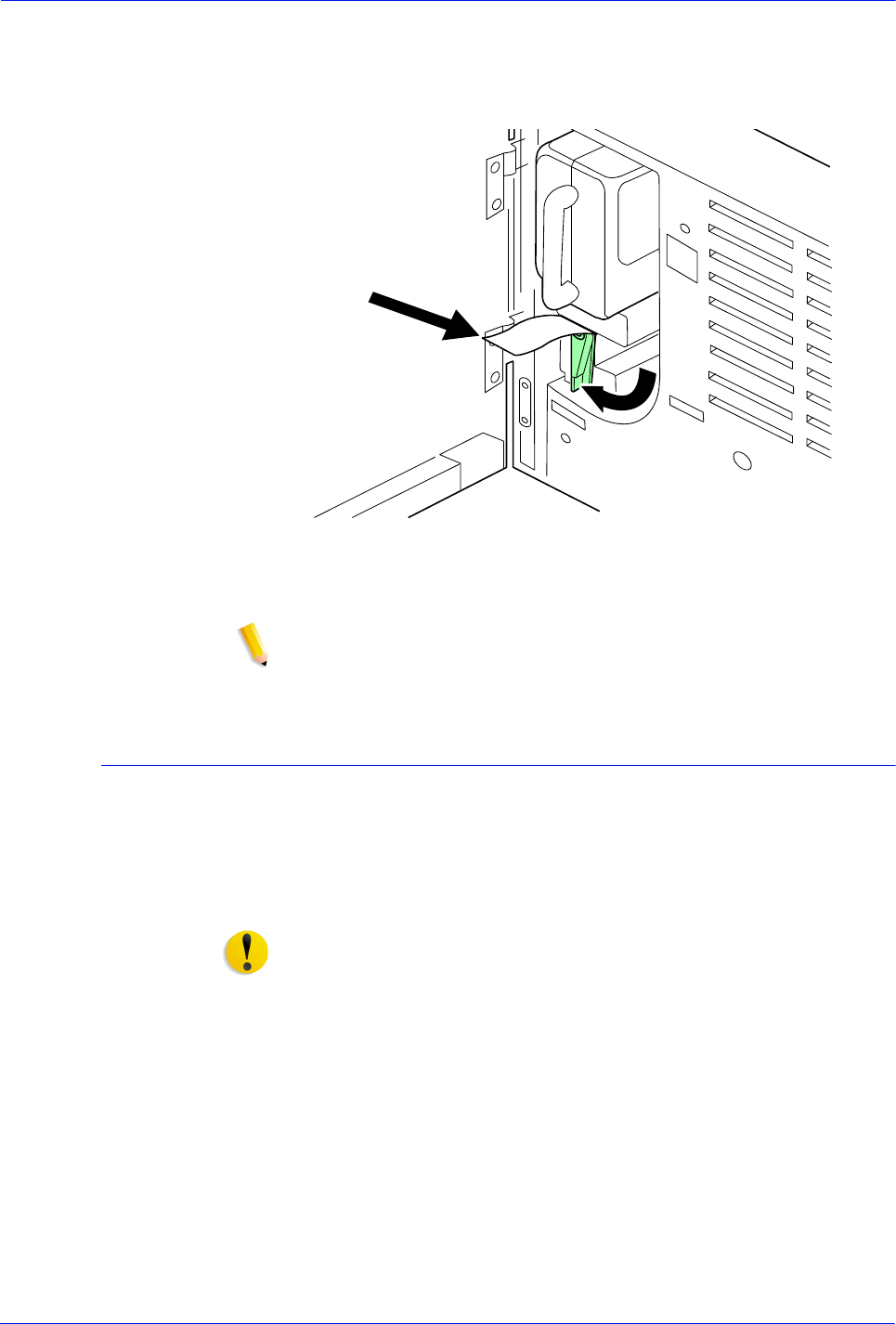
DocuTech 128/155/180 HighLight Color Operator Guide 3-15
Routine maintenance
d. Hold the bottle in place with one hand and remove the
paper seal by pulling it toward you with the other hand.
Discard the seal along with the drop cloth.
Figure 3-10 Removing the paper seal
5. Close the processor access door.
NOTE: If any dry ink should get on your skin, wash with mild
soap and cold water.
Replacing the highlight color container
The highlight color container holds the color dry ink. When
directed by a screen message, replace the highlight color
container. If the highlight color container is not replaced, the
printer stops, and it will not operate until the highlight color
container is replaced.
CAUTION: Do not use warm or hot water, or general cleaning
solvents to remove dry ink from your skin or clothing. The heat or
solvent will set the dry ink and make it difficult to remove. If any
dry ink should get on your skin, wash with mild soap and cold
water.
If any dry ink should get on your clothes, brushing with a dry paper
towel or a stiff-bristled brush may remove the ink. If not, launder
your clothes with detergent and cold water. Tell a commercial dry
cleaner that the spot is dry ink or "toner" so that they will not use a
solvent that will set the dry ink stain.
1. Open the front processor access door and locate the highlight
color container at the right side of the processor.
2. Place a drop cloth on the floor under the highlight color
container area.

3-16 DocuTech 128/155/180 HighLight Color Operator Guide
Routine maintenance
3. Remove the empty container by grasping its handle. With a
slow, firm motion, remove the container.
Figure 3-11 Highlight color container
4. Pull the container out until it stops.
5. Remove the container and discard it.
6. To insert a new bottle, place the bottle on the edge of the bottle
guide. With a slow, firm motion, push the bottle into the
dispense position over the hopper.
7. After the bottle is in the dispense position, remove the seal.
You may encounter some resistance.
8. Close the processor door.

DocuTech 128/155/180 HighLight Color Operator Guide 3-17
Routine maintenance
Changing the highlight color Customer Changeable Units
The highlight color Customer Changeable Unit (CCU) consists of
the color dry ink bottle and supporting equipment. In order to
change the highlight color or to service the wire module, you need
to remove the highlight color CCU from the printer.
If you have more than one highlight color CCU, a CCU cart is
provided to allow you to change and store the CCU. If you have
only one highlight color CCU, a service cart is provided to allow
you to remove the CCU for service.
CAUTION: CCU carts should be used exclusively for changing
and storing CCUs. You should always have at least one empty
cart at your site if your printer has more than one color CCU. Do
not attempt to remove or install a CCU without a cart.
CAUTION: Do not remove the CCU after a hard stop, such as
caused by a paper jam, system crash or restart, or opening a door
during printing, without first allowing the system to cycle up and
continue processing for a proper recovery.
Removing the CCU using the CCU cart
To remove the highlight color CCU from the printer:
1. If the printer is not cycled down, Pause the system before you
open the doors and attempt to remove the CCU.
2. Open the printer doors and locate the color housing area in the
center of the printer.
3. Open the top cover of an empty cart.
4. Push the cart up to the printer, lining up the yellow knob on the
cart with the yellow recess on the printer inner cover.
5. Push the cart firmly against the printer until you can feel the
two latch together.
6. Make sure the cart is level.
a. If the cart is not level, loosen the locknut holding the height
adjustment knob in place.
b. Use the height adjustment knob to regulate the level.
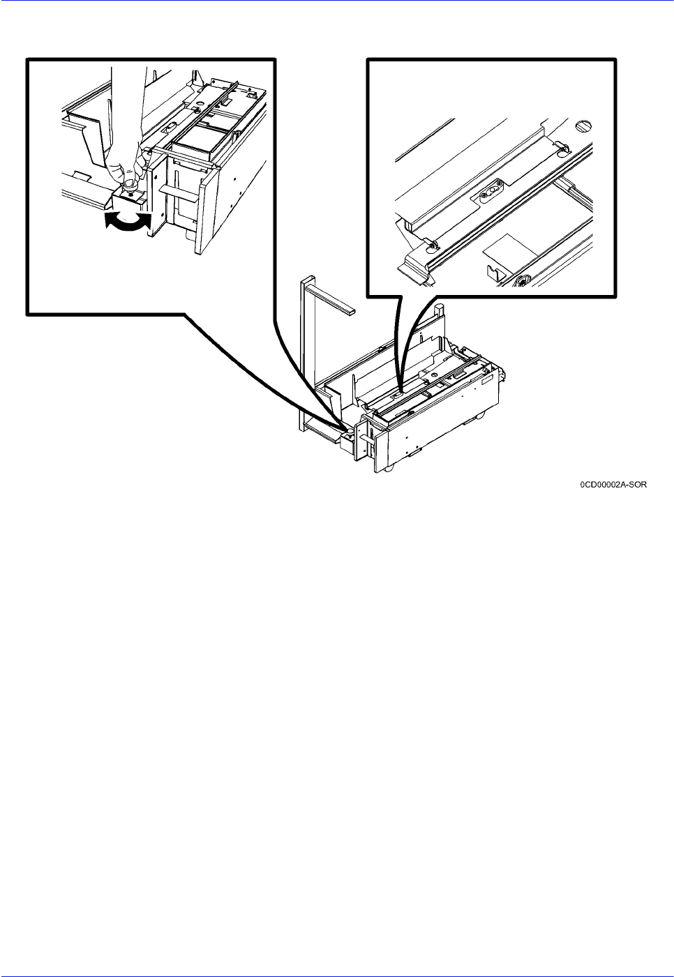
3-18 DocuTech 128/155/180 HighLight Color Operator Guide
Routine maintenance
c. When the HLC unit is level, tighten the lock nut.
Figure 3-12 Leveling the cart
7. Push down firmly on the cart pedal until you hear or feel the
pedal catch. The pedal should stay locked down. The pallet
within the cart is raised.
8. Unlatch the CCU by turning the photoreceptor backup roller
handle clockwise for a quarter turn to an upright position.
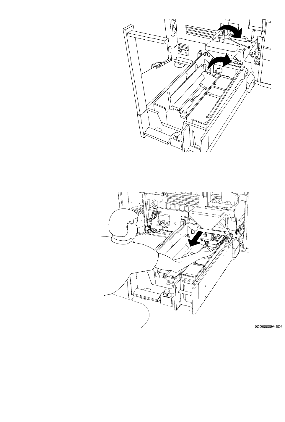
DocuTech 128/155/180 HighLight Color Operator Guide 3-19
Routine maintenance
5. Then, turn the yellow CCU handle a quarter turn clockwise.
Figure 3-13 Unlatching the CCU
9. Using the metal flange of the color CCU, pull the CCU out of
the printer until it is completely in the cart. The flange is
located directly below the bottle.
Figure 3-14 Removing the CCU from the printer
10. Push down firmly on the cart pedal until you hear or feel a
click. The pallet, which now contains the CCU, is lowered into
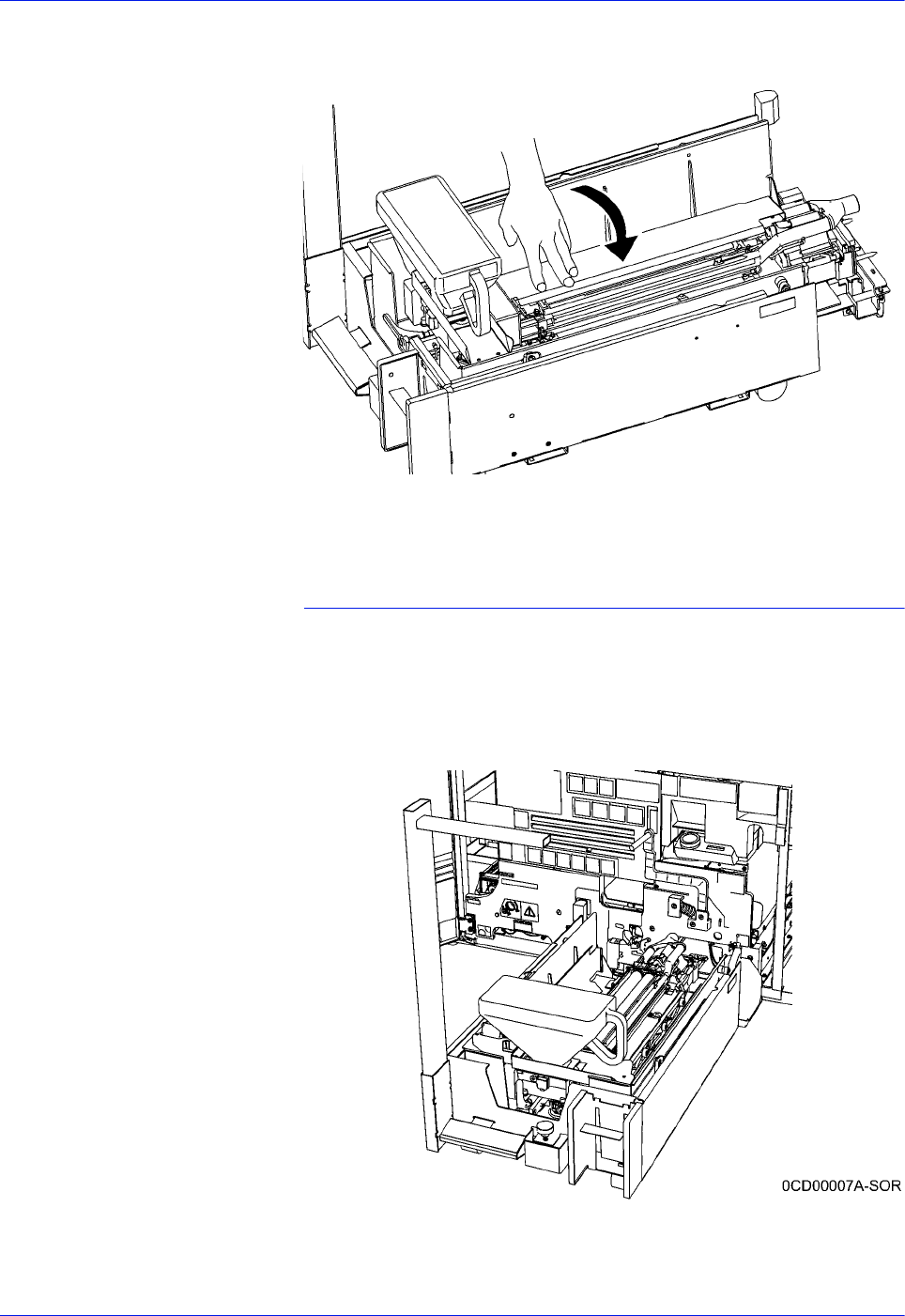
3-20 DocuTech 128/155/180 HighLight Color Operator Guide
Routine maintenance
the cart. If the pallet does not move, check that the CCU is all
the way out of the printer and push down on the pedal again.
Figure 3-15 Closing the top cover
11. Close the top cover and store it.
Inserting a CCU
To insert a CCU, follow these steps.
1. Open the top cover of the cart containing the new color CCU.
2. Push the cart up to the printer, lining up the yellow knob on the
cart with the yellow recess on the printer inner cover. Make
sure the cart is level.
Figure 3-16 CCU on cart
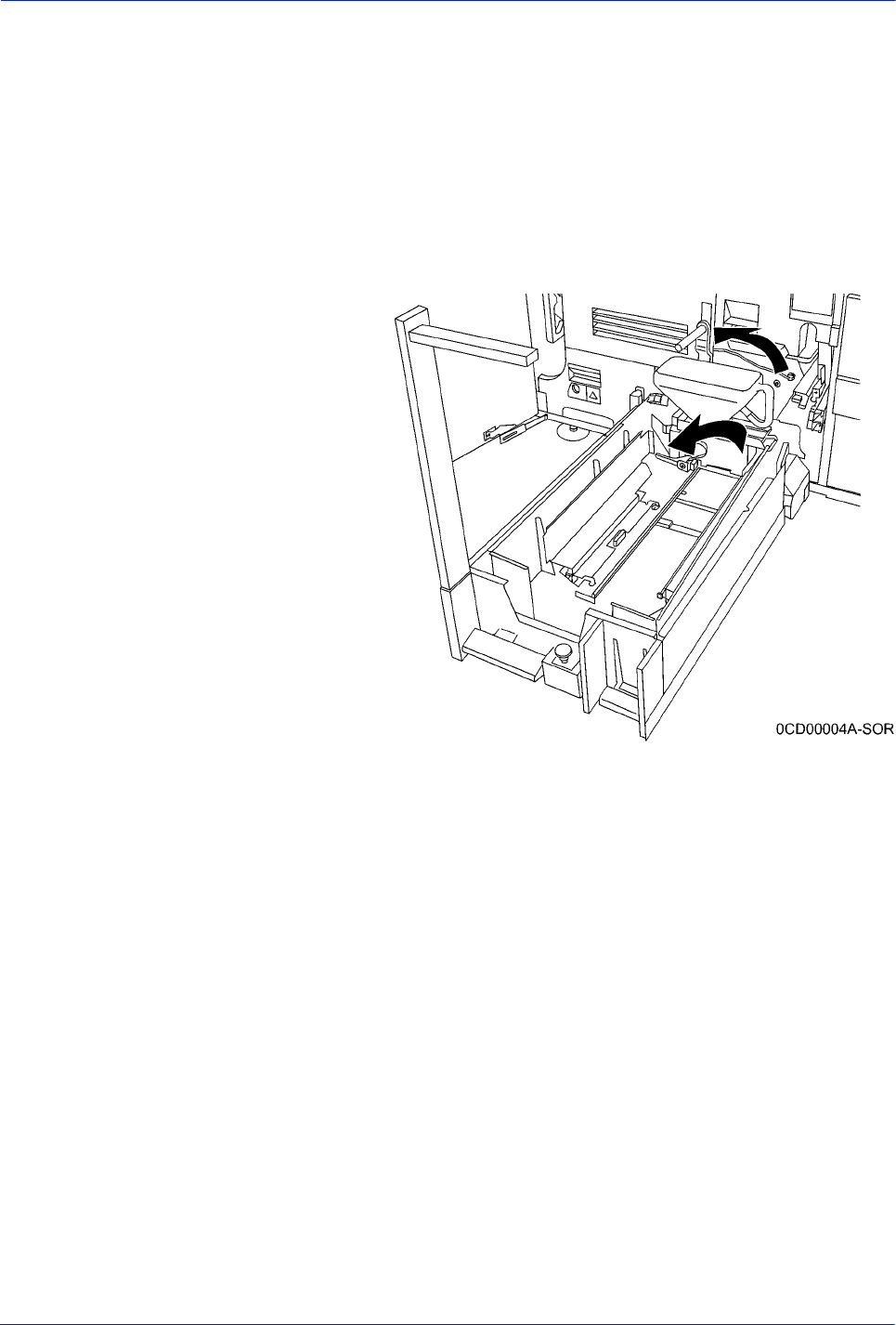
DocuTech 128/155/180 HighLight Color Operator Guide 3-21
Routine maintenance
3. Push the cart firmly against the printer until you can feel the
two latch together.
4. Push down firmly on the cart pedal until you hear or feel the
pedal catch. The pedal should stay locked down. The pallet
containing the CCU is raised.
5. Using the CCU metal flange, firmly push the CCU into the
printer.
6. Turn the yellow CCU handle counterclockwise for a quarter
turn. If it does not turn, check that the CCU is firmly seated in
the printer.
Figure 3-17 Turning the backup roller handle
counterclockwise
7. Turn the photoreceptor backup roller handle counterclockwise
for a quarter turn.
8. Make sure that the CCU is completely inserted into the
machine to prevent photoreceptor damage.
9. Push down firmly on the cart pedal until you hear or feel a
click. If the pallet does not drop, check that the CCU is all the
way in the printer and the pallet is released, then push down
on the pedal again.
10. Remove the cart from the printer and close the cart top cover.
11. Close the printer doors.
12. Store the cart.
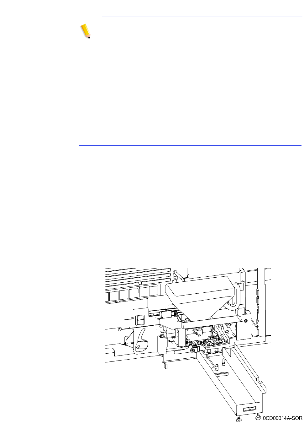
3-22 DocuTech 128/155/180 HighLight Color Operator Guide
Routine maintenance
Storing the cart and CCU
NOTE: If any dry ink gets on your hands, wash them with soap
and cold water. Heat sets the ink permanently. If any dry ink gets
on your clothes, brush them with a dry paper towel or a stiff
bristled brush. If this does not remove the ink immediately, launder
with detergent and cold water. Tell the dry cleaners that the spot is
dry ink for a printer, so they will not use a solvent that sets the
stain.
When you are not using a cart and CCU, store them in a dry, dust-
free area that has little variation in temperature and humidity. The
storage area should have a similar temperature and humidity to
the printer room. Maintain the temperature in the range of 60 to
80° F/15 to 26 C° and a relative humidity of 30 to 65 percent.
Removing the CCU using the service stand
Use the service stand to withdraw the highlight color CCU from the
printer. Use this stand if you do not have a cart.
To set up the service stand:
1. If the printer is not cycled down, Pause the system before you
open the doors and attempt to remove the CCU.
2. Open the printer doors and locate the color housing area in the
center of the printer.
3. Place the service stand next to the developer housing.
4. By turning the jack screws, adjust the height of the front feet so
that the alignment pins in the service stand are positioned just
below the hole and the docking bracket. Tighten the lock nuts
on the jack screws to lock the jack screws in position.
Figure 3-18 Service stand
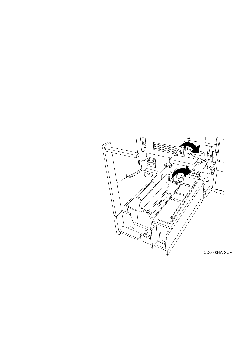
DocuTech 128/155/180 HighLight Color Operator Guide 3-23
Routine maintenance
5. Slide the stand toward the machine to engage the pins with
the holes and the slot. The end of the service stand may need
to be lifted slightly to ensure pin engagement.
6. With the service stand in position against the machine and the
pins engaged in the docking bracket, engage the locking
mechanism by applying a force forward on the lever and
compressing the latch spring while turning it to the position
shown.
7. Locate the pin squarely to the machine by ensuring that the
two (2) locating pins in the service stand are in contact with the
docking bracket.
8. With the service stand properly located to the machine and
while observing the level, turn the rear jack screws to adjust
the height of the service stand so that it is level.
9. Tighten the lock nuts on the jack screws to lock the jack
screws in position.
10. Unlatch the CCU by turning the photoreceptor backup roller
handle clockwise for a quarter turn to an upright position.
Figure 3-19 Unlatching the CCU

3-24 DocuTech 128/155/180 HighLight Color Operator Guide
Routine maintenance
6. Then, turn the yellow CCU handle a quarter turn clockwise.
Figure 3-20 Removing the CCU from the printer
11. Using the metal flange of the color CCU, pull the CCU out of
the printer until it is completely in the stand. The flange is
located directly below the bottle.
12. To replace the CCU, reverse the above steps.
Adding fuser shield
When directed by a message, add fuser lubricant as soon as
possible. If it is not added, the printer stops after approximately
5,000 prints and not run until fuser shield is added. Please read
the important note below.
NOTE: In 2006, the formula for the DocuTech HLC fuser lubricant
was changed to provide better image quality and to prevent image
transfer. The new fuser formula is called Fuser Shield. The fuser
blend and the fuser shield CANNOT be intermixed in a DocuTech
HLC. To change from one fuser lubricant to another requires a
service call and cleaning or replacing components. The two fuser
formulas are identified with different color bottles and caps. Be
sure the color of the cap of the bottle you are filing from matches
the color of the cap already in the system. Fuser shield
description: blue bottle, white cap with black printing. Fuser blend
description: yellow bottle, black cap with white printing.
WARNING: The fuser area can reach temperatures of
approximately 425°F (218°C). Exercise care to prevent burns
when working in this area.
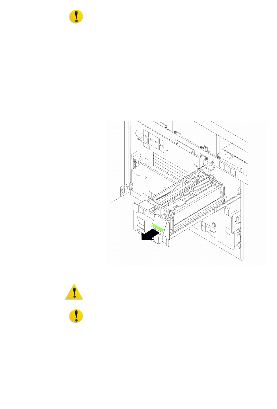
DocuTech 128/155/180 HighLight Color Operator Guide 3-25
Routine maintenance
CAUTION: Fuser lubricant for other printers is not compatible.
Do not use DocuTech and DocuPrint fuser agent in a DocuTech
HLC system. Do not use DocuTech HLC fuser shield in a
DocuTech 61xx or DocuPrint 1xx system. The fuser lubricants are
not compatible and will contaminate the system.
1. Open the processor doors.
2. Place a drop cloth on the floor under the fuser area.
3. Open the fuser drawer.
a. Locate the fuser drawer.
b. Grasp the green handle on the fuser drawer and pull it out
until it stops.
Figure 3-21 Opening the fuser drawer
WARNING: Fuser lubricant contains silicone, which can cause
irritation upon contact with the eye. Make sure that you wash your
hands with soap and water after you finish this procedure.
CAUTION: Fuser lubricant can cause damage to the CCU if any
of the it is spilled into the unit. Use extra care to ensure that no
fuser lubricant is dripped into the CCU.
4. Wipe the fuser lubricant filler area to remove any residual
lubricant.
5. Fill the fuser lubricant reservoir.
a. Pull the fuser lubricant reservoir out until it stops.
b. Remove the reservoir cap by turning it counterclockwise.
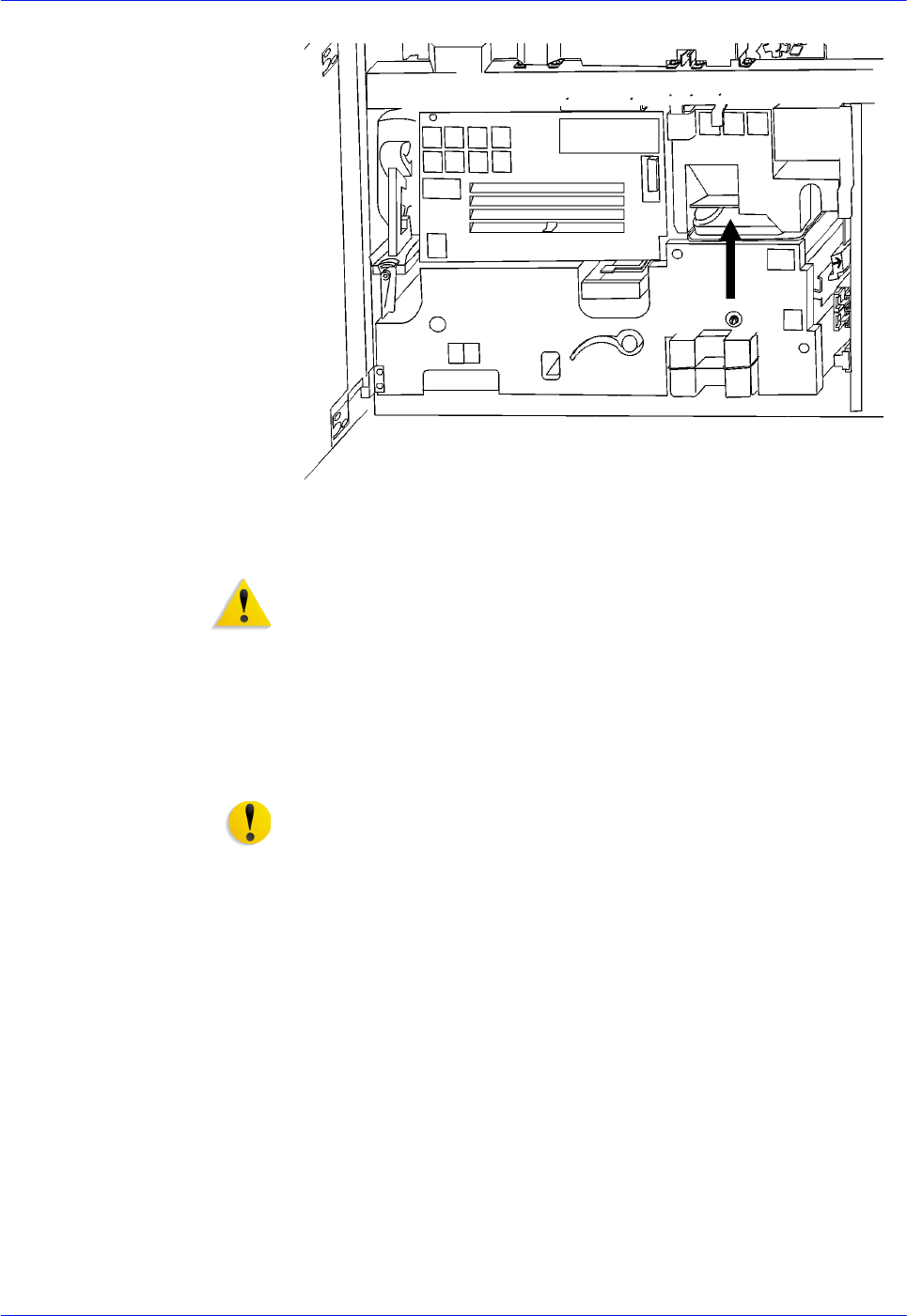
3-26 DocuTech 128/155/180 HighLight Color Operator Guide
Routine maintenance
Figure 3-22 Preparing to add fuser blend
WARNING: Fuser lubricant spills cause the floor to be slippery. If
any fuser lubricant is spilled onto the floor, it must be removed
immediately.
c. Open a new box of fuser lubricant and remove a bottle.
Remove the cap from the bottle of fuser lubricant.
d. Carefully pour the fuser lubricant into the reservoir until the
level reaches the MAX line. Avoid spilling the fuser
lubricant or overfilling the reservoir.
CAUTION: Do not push the fuser lubricant bottle into the
reservoir with excessive force. There is an anti-splash seal in the
reservoir that could be damaged.
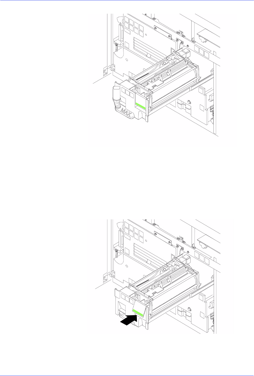
DocuTech 128/155/180 HighLight Color Operator Guide 3-27
Routine maintenance
Figure 3-23 Adding the fuser blend
e. Replace the reservoir cap by turning it clockwise
approximately one full turn. Do not overtighten the cap.
f. Inspect the area around the fuser to ensure no fuser blend
was spilled. Clean as required.
g. Push the fuser blend reservoir in until it stops.
6. Push the fuser drawer in until it latches into place.
Figure 3-24 Closing the fuser drawer

3-28 DocuTech 128/155/180 HighLight Color Operator Guide
Routine maintenance
7. Close the processor doors.
The fuser blend message disappears after the system makes
approximately 20 prints.
Waste containers
The waste containers in the DT 128/155/180 HLC collect dry ink
and developer after it has been used by the printer. When a
container becomes full, it must be replaced or the printer
eventually stops printing. This section contains the procedures for
replacing the toner and developer waste containers.
Replacing the 128/155/180 HLC developer waste container
To replace the developer waste container:
1. Open the processor doors and locate the dry ink cartridge at
the lower center of the printer. The developer waste container
is located below and to the right of the color dry ink bottle.
Figure 3-25 HLC developer waste container
2. Using your right hand, grasp the container by the handle on
top. With your thumb, depress the latch located above the
frame of the machine. Lift the edge of the container from the
tray and remove. Unscrew the cap from the front of the waste
container and use it to close the open end of the waste
container.
3. Discard the waste material and container appropriately.
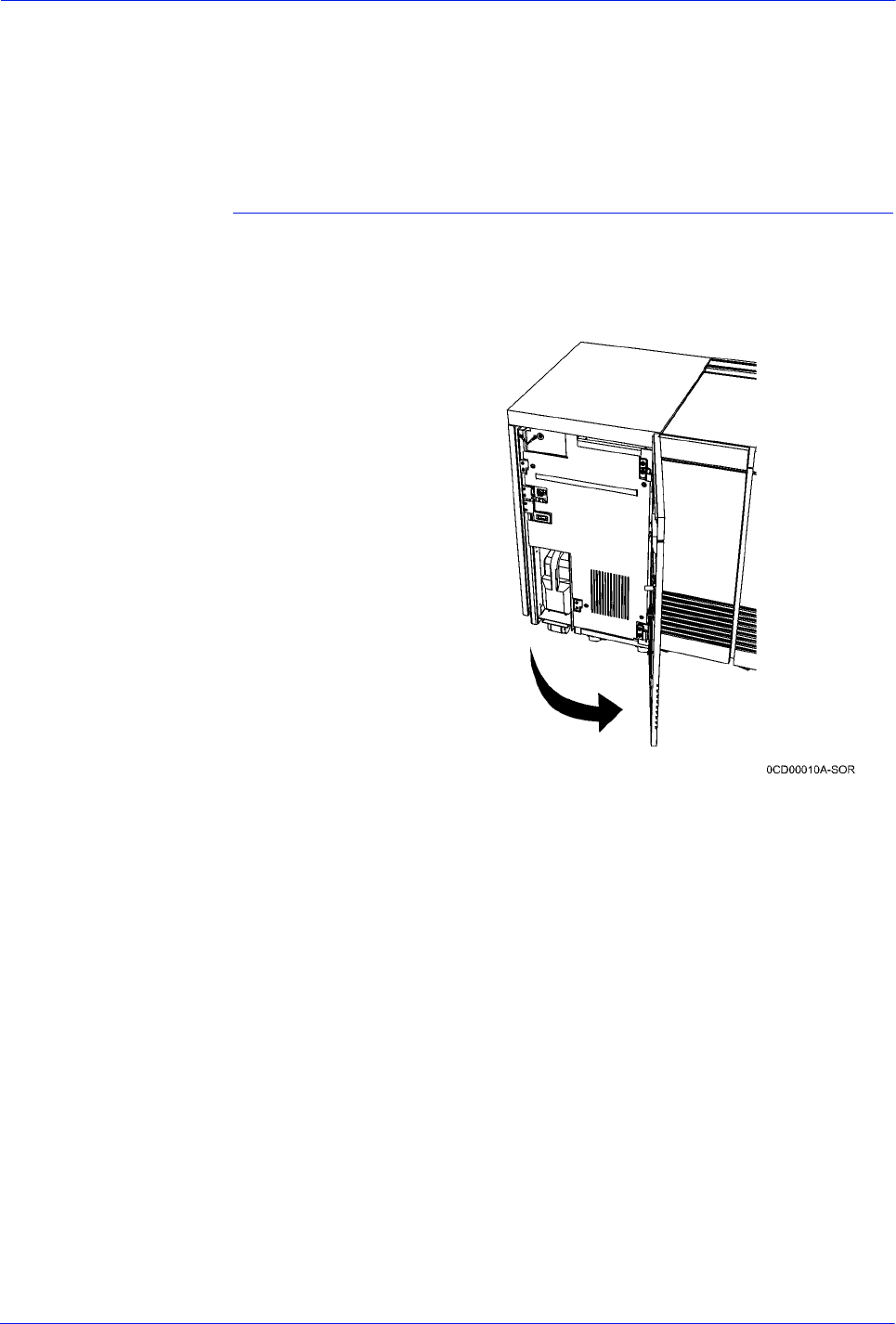
DocuTech 128/155/180 HighLight Color Operator Guide 3-29
Routine maintenance
4. Insert the new waste HLC developer waste container into the
transport assembly. Push the retainer out of the way with your
thumb. Continue seating the new waste container onto the tray
and release the container latch.
5. Close the processor doors.
Replacing the 128/155/180 toner waste bottle
To replace the toner waste bottle:
1. Open the HLC module door.
Figure 3-26 Opening the HLC module door
2. Remove the toner waste bottle.
3. Remove the flat cap from the top front of the bottle.
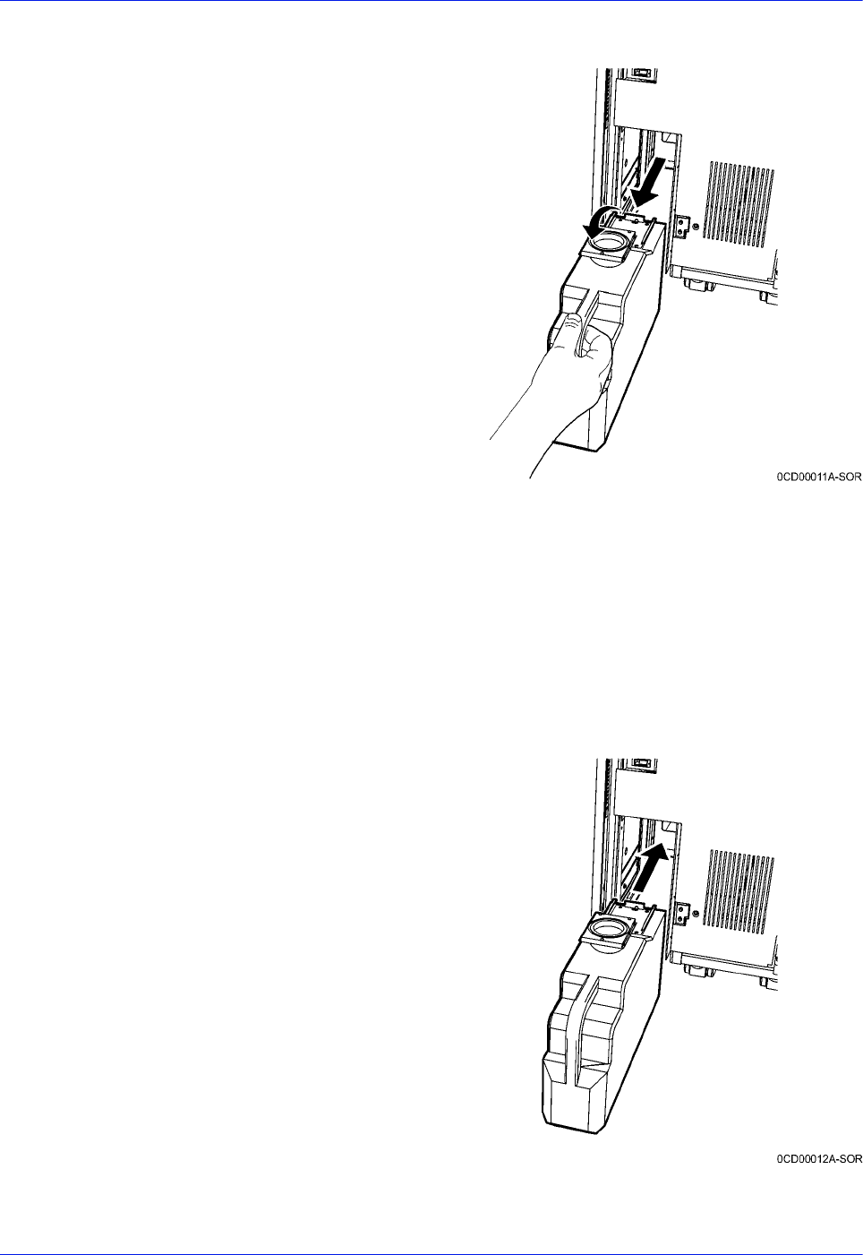
3-30 DocuTech 128/155/180 HighLight Color Operator Guide
Routine maintenance
Figure 3-27 Flat cap on waste bottle
4. Place the flat cap on the round bottle opening and snap it
down. This prevents spillage when discarding the bottle.
5. Discard the waste material and container by placing the
container in the trash.
6. Obtain a new bottle and open it, placing the cap at the front of
the bottle and snapping it down.
7. Insert the new bottle into the waste module.
Figure 3-28 Inserting a new waste bottle
8. Close the HLC module door.
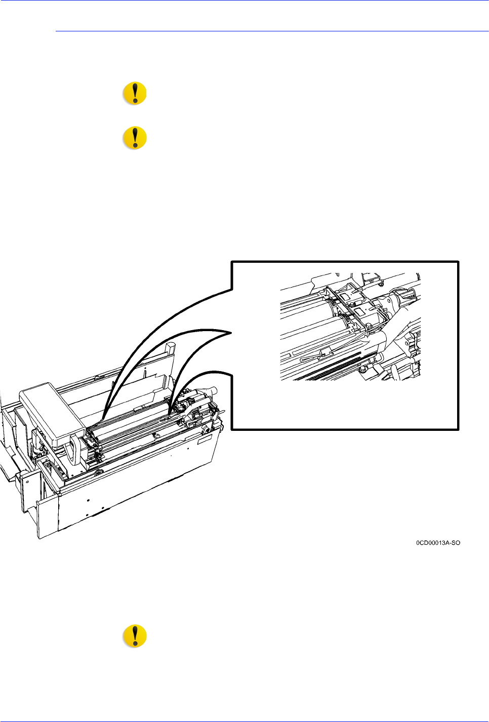
DocuTech 128/155/180 HighLight Color Operator Guide 3-31
Routine maintenance
Wire Module Removal and Replacement
Replace the wire module only when directed to by the Customer
Support Center.
CAUTION: In the following instructions, do not pull on the locating
arm of the developer housing. A bent or damaged locating arm
can cause component damage or image quality artifacts.
Do no touch the Electrostatic Voltage (ESV) mounted to the top of
the developer housing when removing the wire module. The ESV
is fragile, and susceptible to damage from electrostatic discharge.
To remove the wire module:
1. Open the processor doors.
2. Using the CCU cart or service stand, slide the HLC developer
module out of the printer Refer to the procedures on using the
CCU cart or service stand.
Figure 3-29 Wire module retainer springs
3. Release the wire module retainer springs. There is one at
each end at the front and back of the developer housing.
CAUTION: Handle the wire module with care since the wires can
be damaged or broken easily. Do not touch the donor rolls.
Touching the roll surface with your fingers can contaminate the
surface, causing image quality problems.
To replace the wire module:
1. Position the wire module on the HLC developer module.
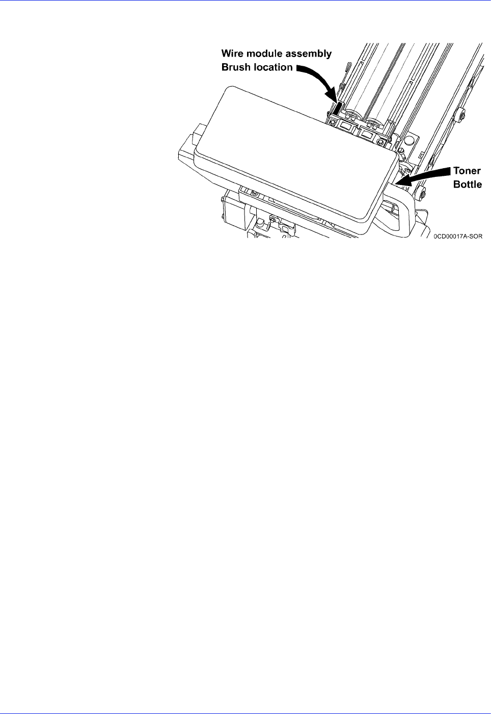
3-32 DocuTech 128/155/180 HighLight Color Operator Guide
Routine maintenance
2. Ensure that the brush on the wire module is at the toner bottle
end as shown in the figure below.
Figure 3-30 Wire module assembly brush location.
3. Snap the wire module retainer springs behind the tabs.
4. Slide the HLC developer module into the machine.
5. Latch the CCU into place.
6. Remove the cart or service stand.
7. Close the doors.

DocuTech 128/155/180 HighLight Color Operator Guide 3-33
Routine maintenance
Cleaning the system and its components
NOTE: Follow the procedures in this section only when directed
by Xerox Customer Support center personnel.
Cleaning tasks consist of the following:
• Cleaning the 18/36-track cartridge tape drive
• Cleaning the 26-track cartridge tape drive
• Cleaning the DVD drive
• Cleaning the diskette drive
• Cleaning the sensors and the reflecting surfaces
• Cleaning the display
• Cleaning the exterior surfaces of the system
Cleaning the 18/36-track cartridge tape drive
A cleaning cartridge is shipped with each 18/36-track cartridge
tape drive. This cartridge should be replaced after 500 uses.
When the tape drive needs to be cleaned, CLEAN appears in the
message display after a cartridge is unloaded and during a rewind
or locate operation.
NOTE: CLEAN is a status message, not an error message.
CAUTION: Never power off the tape drive without following the
cleaning procedure once the CLEAN message appears.
CAUTION: The cleaning cartridge must be undamaged and
clean.
To clean the 18/36-track cartridge tape drive read/write heads:
1. Remove any cartridge loaded in the tape drive.
2. Insert the cleaning cartridge.
The cleaning cycle takes approximately 15 seconds.
3. Remove the cleaning cartridge when it is unloaded.
4. Mark the usage on the tape label. Do not use a grease pencil.
You must clean the 18/36-track cartridge tape drive regularly to
keep it functioning properly.

3-34 DocuTech 128/155/180 HighLight Color Operator Guide
Routine maintenance
Cleaning the 26-track cartridge tape drive
The 26-track, or quarter inch cartridge (QIC) tape drive heads
should be cleaned at least once a week. If you use the drive for
eight hours or more per day, then you should clean the drive daily.
The process is simple and requires little time.
1. If there is a cartridge in the tape, remove it.
2. Insert the cleaning cartridge in the tape drive and close the
door. Cleaning begins automatically once the tape is inserted.
3. Allow the tape to run for approximately 30 seconds, then
remove it.
NOTE: Replace the foam pad on the cleaning cartridge after it
has been used three times. The cleaning cartridge itself can
be used 100 times.
Cleaning the DVD drive
Follow the DVD cleaning directions and recommended cleaning
frequency.
1. If there is a DVD disk in the drive, remove it.
2. Follow the directions to clean the DVD drive.
Cleaning the diskette drive
The floppy disk drive must be cleaned at recommended intervals
to prevent read and write disk errors.
To clean the diskette drive:
1. If there is a diskette in the floppy disk drive, remove it.
2. Insert the cleaning diskette into the disk drive.
3. Follow the directions on the cleaning diskette to clean the
diskette drive.
4. Remove the cleaning diskette.

DocuTech 128/155/180 HighLight Color Operator Guide 3-35
Routine maintenance
Cleaning the sensors and the reflecting surfaces
CAUTION: Never use abrasive materials or strong solvents when
cleaning sensors.
The following is a list of sensors to clean:
• Q850 and Q861 sensor
• Q1011/1009 sensor and mirror
• High Capacity Feeder/Stacker configuration
• Q1106 sensor
• Q1166 sensor
• Q1107 sensor
• Q1164 sensor
• Production publisher configuration (finisher sensors)
• Q1201 sensor
• Q1202 and Q1203 sensors
• Q1205, Q1206, and Q1207 sensors
• Q1213 sensor
• Q1221, Q1218, and Q1227 sensors
• Q1222 and Q1210 sensors
Cleaning the Q850 and Q861 sensor
1. Open the right and left doors of the printer and locate Area 4.
2. Raise the Area 4 green handle until it locks into place.
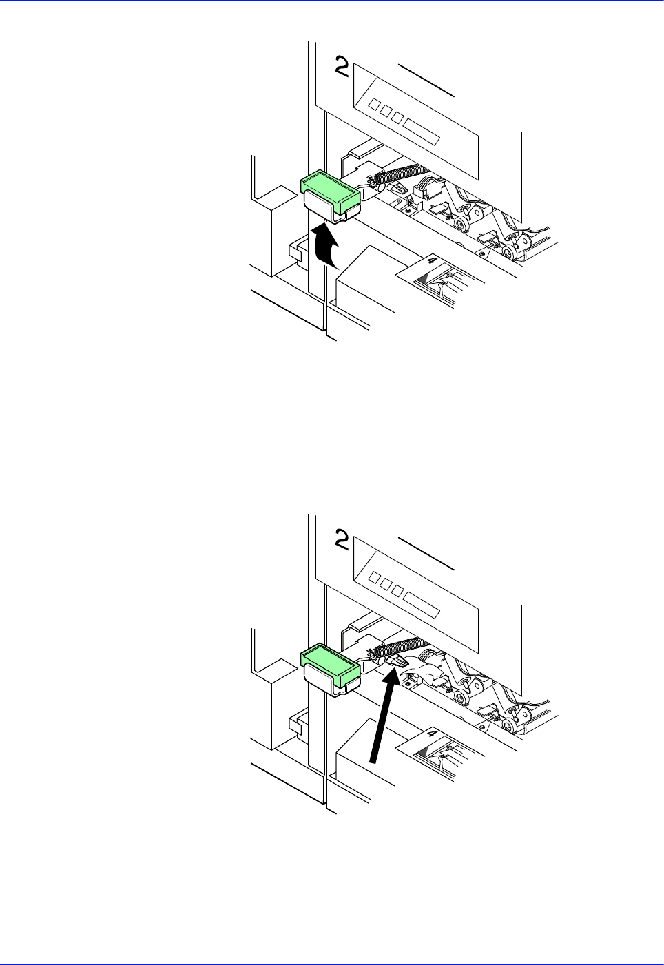
3-36 DocuTech 128/155/180 HighLight Color Operator Guide
Routine maintenance
Figure 3-31 Area 4 and green handle
3. Locate the Q850 and Q861 sensor.
Figure 3-32 Q850 and Q861 sensor
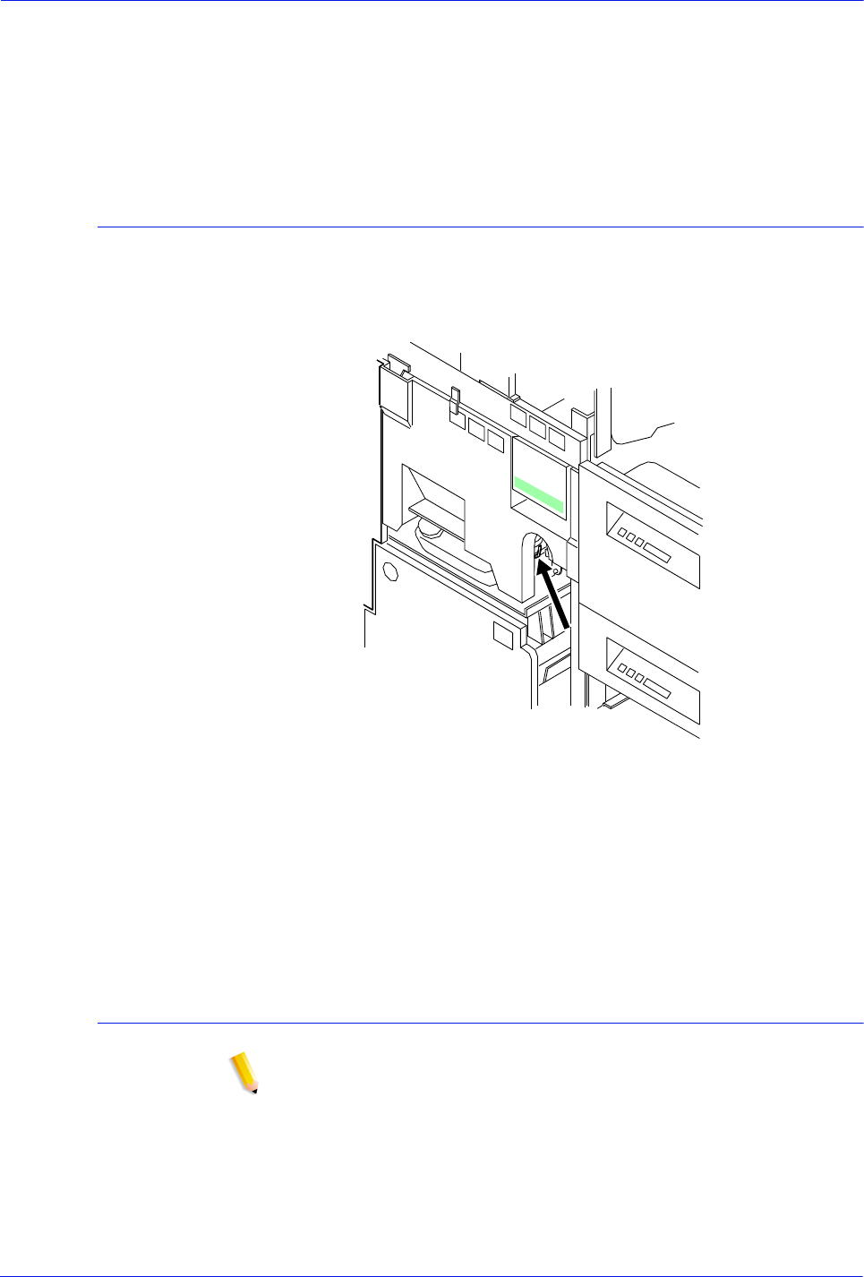
DocuTech 128/155/180 HighLight Color Operator Guide 3-37
Routine maintenance
4. Place a dry cleaning pad on the sensor and move it from left to
right to clean the sensor.
5. Lower the Area 4 green handle.
6. Close the printer doors.
Cleaning the Q1011/1009 sensor and mirror
1. Open the right and left doors of the printer and locate the
Q1011/1009 sensor.
Figure 3-33 Q1011/1009 sensor and mirror
2. Apply a small amount of lens and mirror cleaner to a cleaning
pad.
3. Wipe the sensor gently with the cleaning pad.
Cleaning the Q1106 and Q1166 sensors
NOTE: High volume printer configuration only
To access sensors Q1106 and Q1166, open the top cover of the
high capacity stacker.
To clean the sensors:
1. Brush or wipe the sensor windows lightly.
2. Remove any dust present in the area.
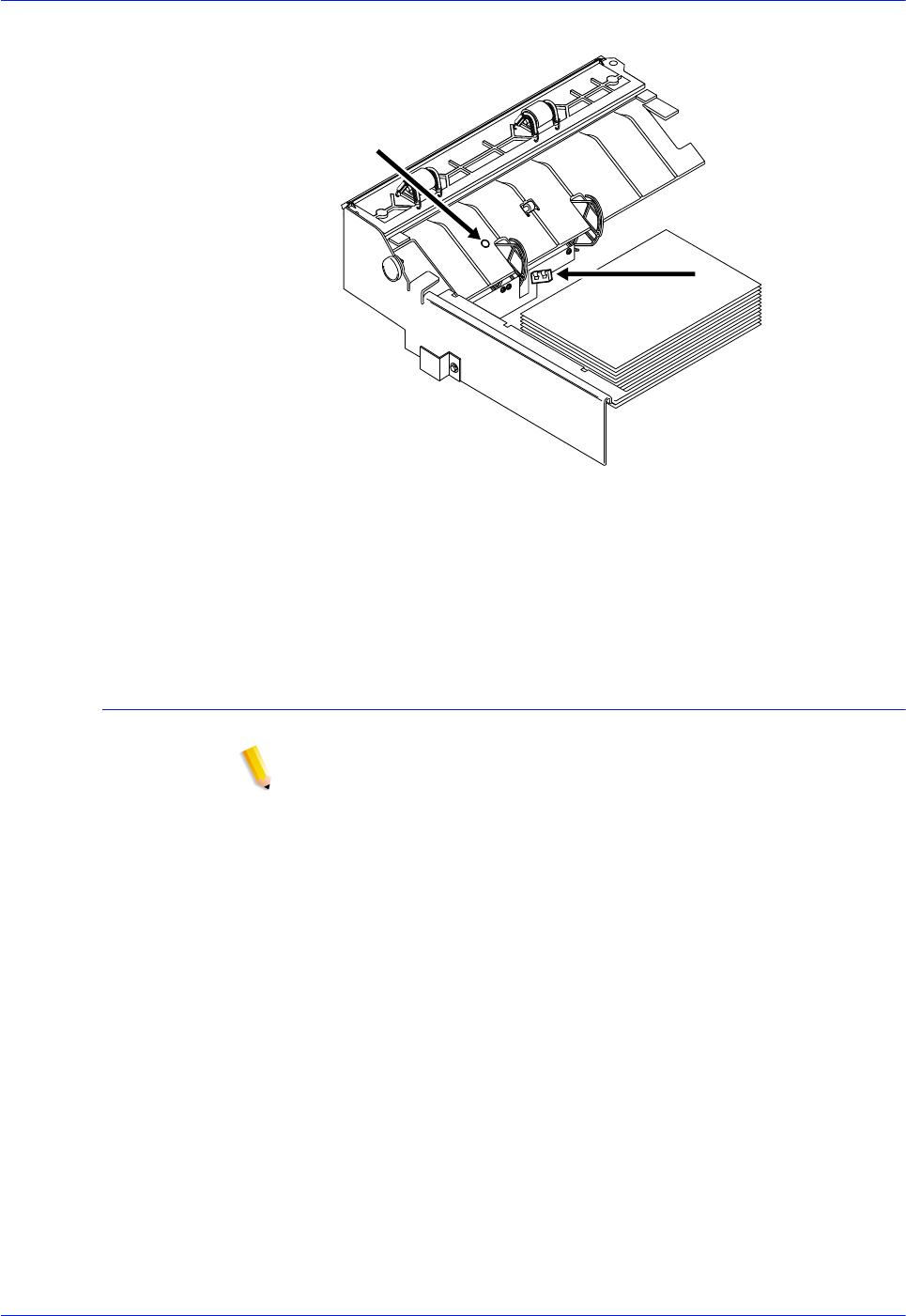
3-38 DocuTech 128/155/180 HighLight Color Operator Guide
Routine maintenance
Figure 3-34 Q1106 and Q1166 sensors
Cleaning the Q1107 sensor
NOTE: High volume printer configuration only
To access sensor Q1107, open the top cover of the high capacity
stacker.
To clean the sensor:
1. Brush or wipe the sensor windows lightly.
2. Remove any dust present in the area.
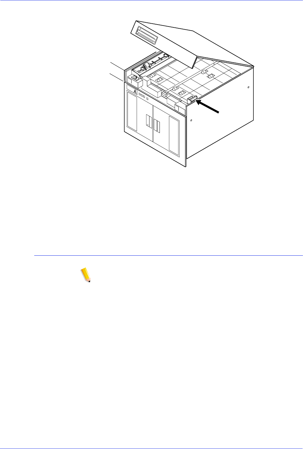
DocuTech 128/155/180 HighLight Color Operator Guide 3-39
Routine maintenance
Figure 3-35 Q1107 sensor
Cleaning the Q1164 sensor
NOTE: High volume printer configuration only
To access sensor Q1164, open the top cover of the last feeder/
stacker module, the one containing the purge tray.
To clean the sensor:
1. Brush or wipe the sensor windows lightly.
2. Remove any paper dust present in the area.
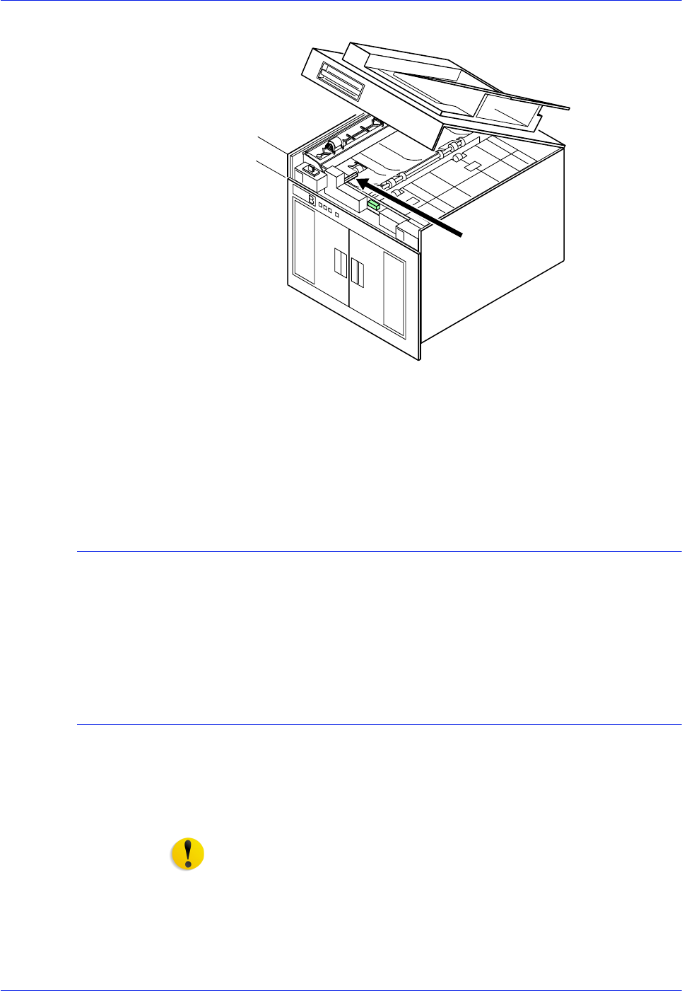
3-40 DocuTech 128/155/180 HighLight Color Operator Guide
Routine maintenance
Figure 3-36 Q1164 sensor
Cleaning the display
The display should be cleaned as required.
Clean the display with a soft, lint-free cloth dampened with a glass
or lens and mirror cleaner. Do not spray the liquid directly onto the
display because it may cause damage.
Cleaning the exterior surfaces of the system
Clean the exterior surfaces of the printer daily, if possible.
Clean the exterior surfaces with a mild household detergent that
has been poured or sprayed onto a cloth lightly dampened with
water. Do NOT saturate the cloth; just dampen it.
CAUTION: Liquids must not be allowed to drip onto anything
electrical or mechanical. Also, never spray or pour any cleaner
directly onto the keyboard or the exterior surfaces of the system.
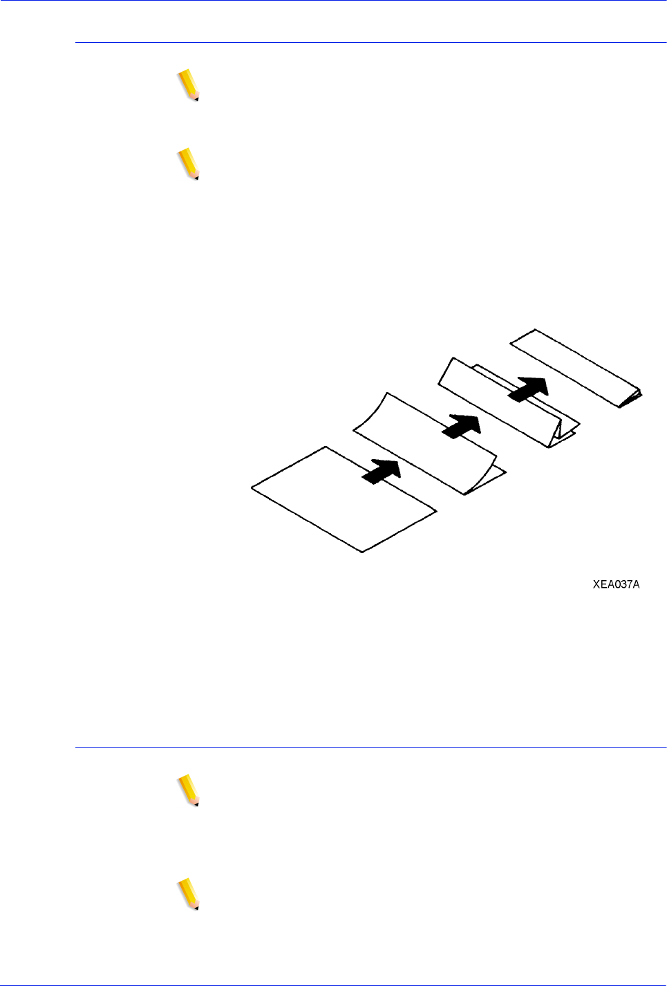
DocuTech 128/155/180 HighLight Color Operator Guide 3-41
Routine maintenance
Clearing or cleaning the finisher sensors
NOTE: Production publisher configuration only
Clearing the finisher sensors should be performed only when
directed by a Customer Support Center Representative.
NOTE: The finisher sensors are located under the processor top
cover, under the finisher top cover, and behind the finisher and
bindexer doors.
Use the following procedure to clear any obstructions from the
finisher sensors.
1. Fold a sheet of 8.5 x 11 inch (216 x 279 mm) paper, as shown
in figure 3-36.
Figure 3-37 Folding the paper
2. Use the folded sheet of paper to clear any obstructions in the
following sensor areas.
Clearing the Q1201 sensor
NOTE: Production publisher configuration only
Clearing the Q1201 sensor should be performed only when
directed by a Customer Support Center Representative.
1. Open the processor top cover.
NOTE: The Q1201 sensor is located under the processor top
cover on the right side.
2. Locate the Q1201 sensor, as shown in figure 3-37

3-42 DocuTech 128/155/180 HighLight Color Operator Guide
Routine maintenance
Figure 3-38 Locating the Q1201 sensor
3. Brush a folded sheet of paper under the sensor to clear any
obstructions.
4. Close the processor cover.
Clearing the Q1202 and Q1203 sensors
NOTE: Production publisher configuration only
Clearing the Q1202 and Q1203 sensors should be performed only
when directed by a Customer Support Center Representative.
1. Open the finisher top cover.
2. Locate the Q1202 and Q1203 sensors, as shown in figure 3-
38.
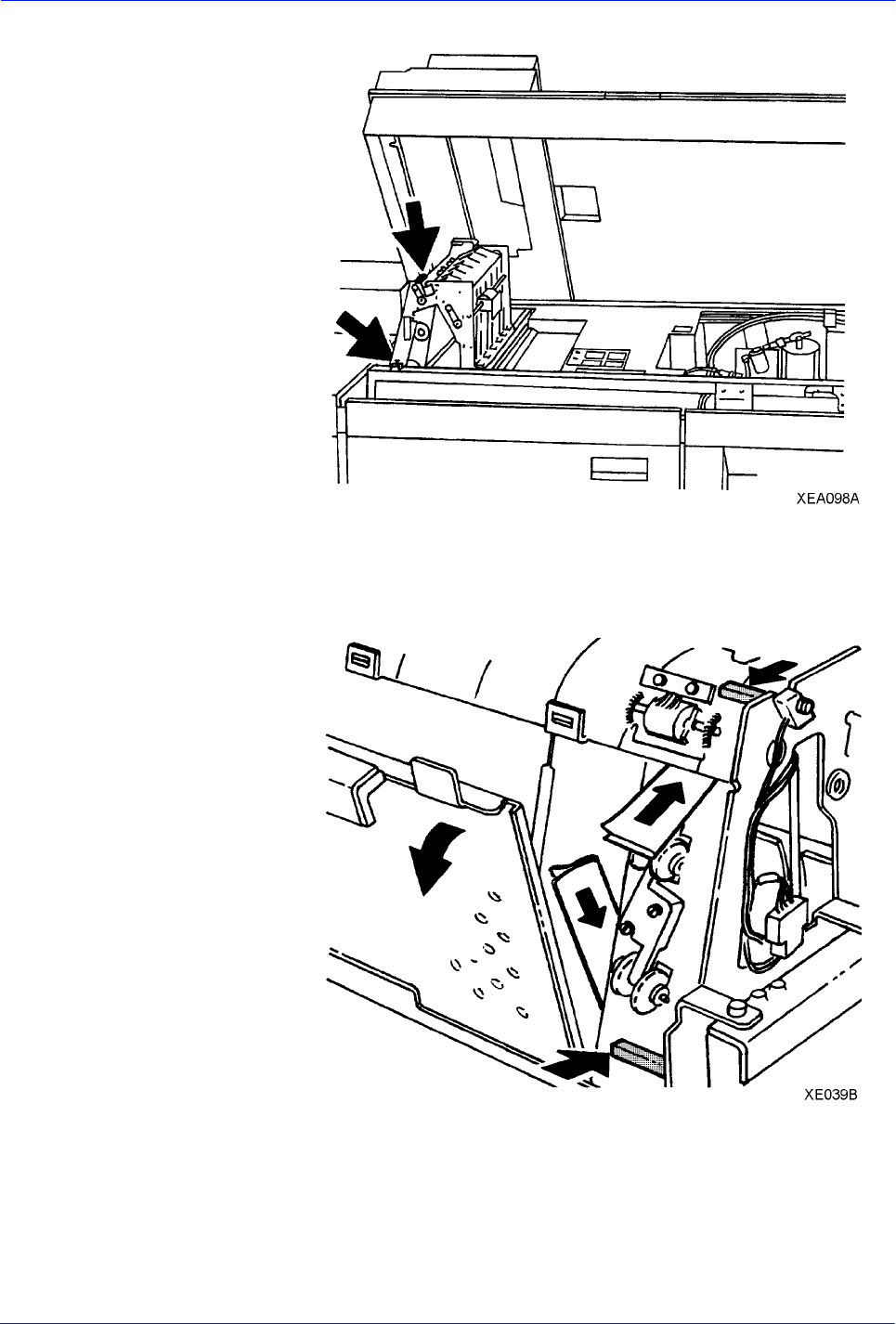
DocuTech 128/155/180 HighLight Color Operator Guide 3-43
Routine maintenance
Figure 3-39 Locating the Q1202 and Q1203 sensors
3. Brush a folded sheet of paper under each sensor to clear any
obstructions, as shown in figure 3-39.
Figure 3-40 Clearing the Q1202 and Q1203 sensors
4. Close the finisher top cover.
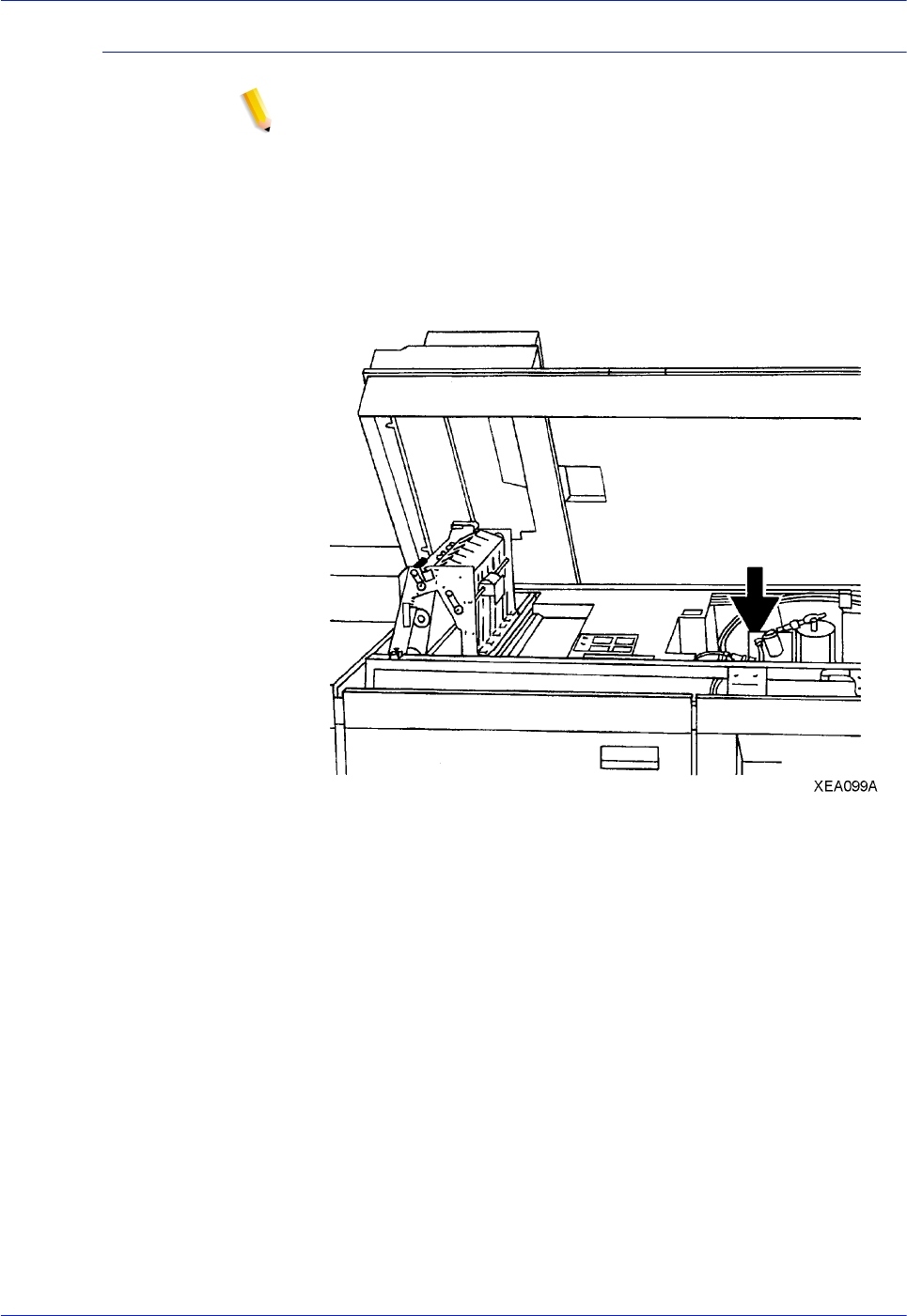
3-44 DocuTech 128/155/180 HighLight Color Operator Guide
Routine maintenance
Cleaning the Q1222 and Q1210 sensors
NOTE: Production publisher configuration only
Cleaning the Q1222 and the Q1210 sensors should be performed
only when directed by a Customer Support Center
Representative.
1. Open the finisher top cover.
2. Look down at the rear section of the tilt bed area, as shown in
figure 3-40, to view the sensors.
Figure 3-41 Locating the Q1222 and Q1210 sensors
3. Locate the Q1222 and Q1210 sensors, as shown in figure 3-
41
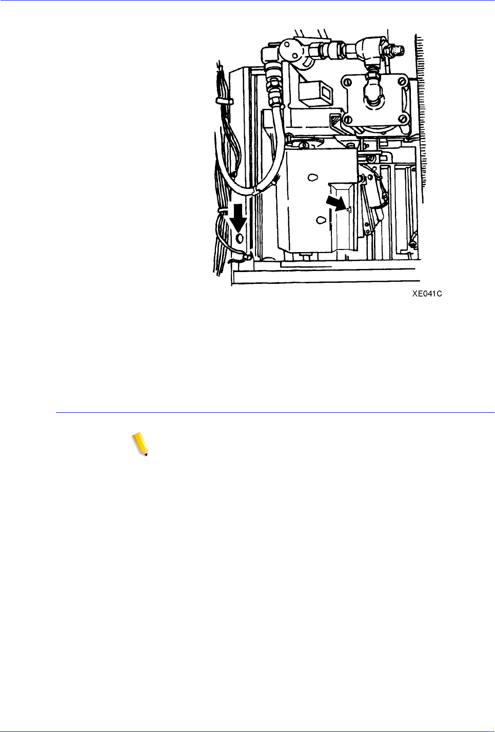
DocuTech 128/155/180 HighLight Color Operator Guide 3-45
Routine maintenance
Figure 3-42 Locating the Q1222 and Q1210 sensors
4. Wipe each sensor gently with a soft cloth to clean them.
5. Close the finisher top cover.
Clearing the Q1205, Q1206, and Q1207 sensors
NOTE: Production publisher configuration only
Clearing the Q1205, Q1206, and Q1207 sensors should be
performed only when directed by a Customer Support Center
Representative.
1. Open the finisher front doors.
2. Open the bindexer door.
3. Locate the Q1205, Q1206, and Q1207 sensors, as shown in
figure 3-42.
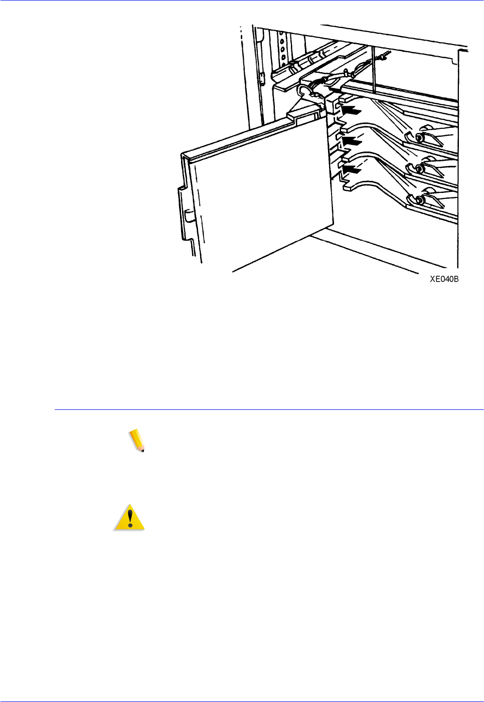
3-46 DocuTech 128/155/180 HighLight Color Operator Guide
Routine maintenance
Figure 3-43 Locating the Q1205, Q1206, and Q1207 sensors
4. Brush a folded sheet of paper across each sensor to clear any
obstruction.
5. Close the bindexer and finisher doors.
Clearing the Q1213 sensor
NOTE: Production publisher configuration only
Clearing the Q1213 sensor should be performed only when
directed by a Customer Support Center Representative.
1. Open the finisher doors.
WARNING: The top of the binder is approximately 425°F (218°C).
Do not touch the heated areas or you may get burned. If the
binder has been in a "Ready" condition, allow it to cool for at least
1 hour before continuing the procedure.
2. Grasp the green handle on the binder drawer. Pull the drawer
out until it stops.
3. Locate the Q1213 sensors, as shown in figure 3-43
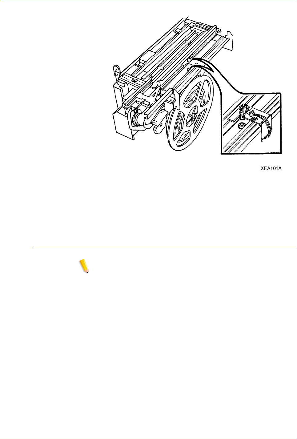
DocuTech 128/155/180 HighLight Color Operator Guide 3-47
Routine maintenance
Figure 3-44 Q1213 sensor
4. Brush a folded sheet of paper across the sensor to clear any
obstruction.
5. Close the binder drawer and the finisher doors.
Clearing the Q1221, Q1218, and Q1227 sensors
NOTE: Production publisher configuration only
Clearing the Q1221, Q1218, and Q1227 sensors should be
performed only when directed by a Customer Support Center
Representative.
1. Open the finisher front doors.
2. Locate the Q1221, Q1218, and Q1227 sensors, as shown in
figure 3-44.
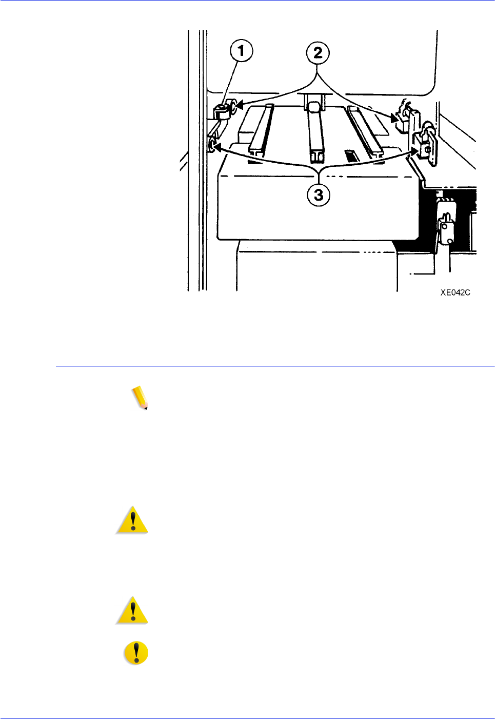
3-48 DocuTech 128/155/180 HighLight Color Operator Guide
Routine maintenance
Figure 3-45 Locating the Q1221, Q1218, and Q1227 sensors
Cleaning the binder
NOTE: Production publisher configuration only
Keep the binder clean to prevent binder tape jams. Clean the
binder once a week, or as needed, and also when changing the
binder tape.
It is highly recommended that the binder be cleaned before the
binder warm-up cycle begins or before switching the system on.
The following steps must be performed to clean the binder.
WARNING: All areas of the binder drawer, including the binder
tape, are hot, approximately 425°F (218°C), and may cause a
serious burn. If the binder has been in a "Ready" condition, allow
the binder to cool for at least one hour before continuing the
procedure.
1. Open the finisher doors.
WARNING: A sharp edge on the plastic binder platen cleaner or
on the tape spool sometimes occurs as a result of removing the
cleaner. This sharp edge could cause finger cuts.
CAUTION CAUTION: To avoid damage to the system, do not use any
liquids or any abrasive material to clean the binder. Use the plastic
binder platen cleaner on the tape reel or use a clean, lint-free
cloth.
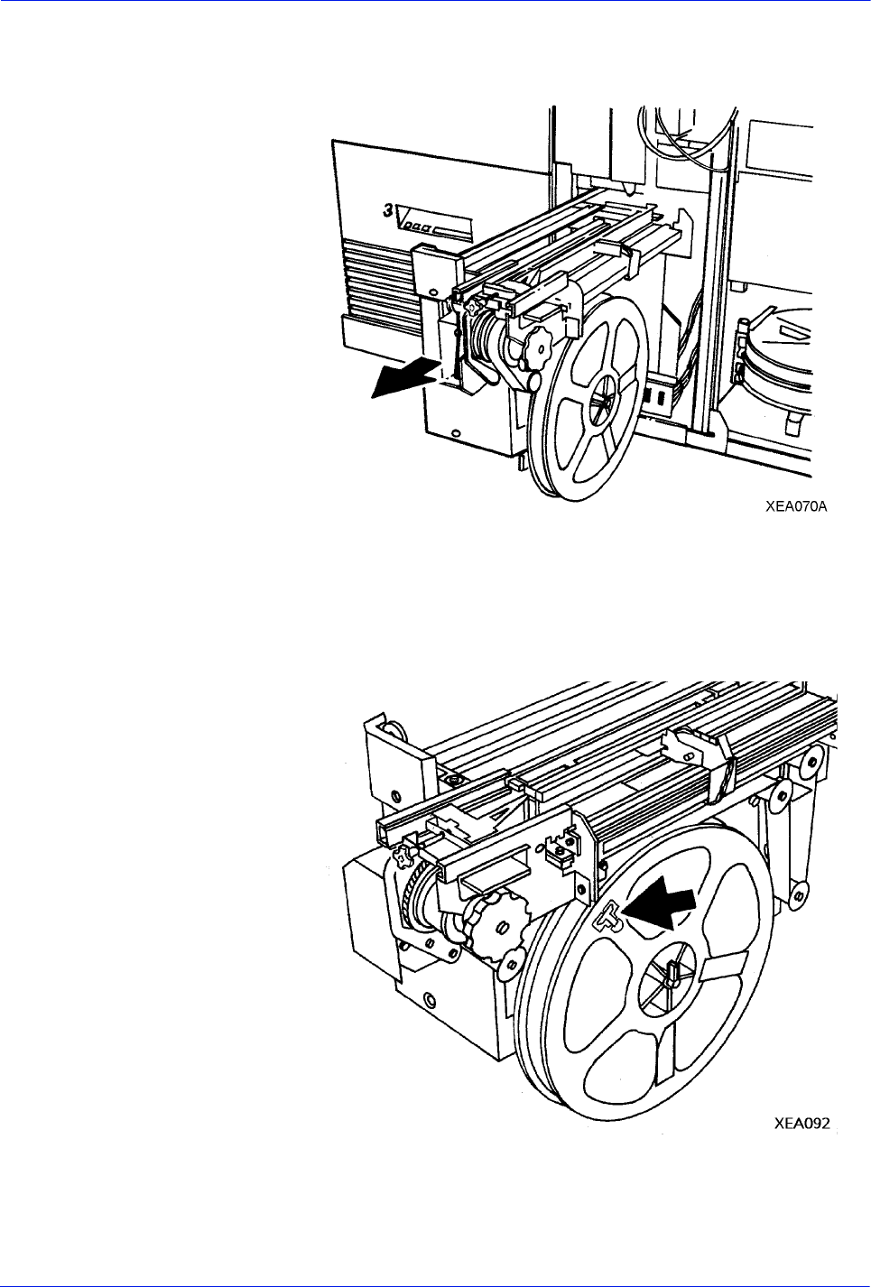
DocuTech 128/155/180 HighLight Color Operator Guide 3-49
Routine maintenance
2. Grasp the green handle on the binder drawer. Pull the drawer
out until it stops.
Figure 3-46 Opening the binder drawer
3. Perform the following steps:
a. Locate and remove the plastic binder platen cleaner from
the binder tape reel, as shown in the following figure.
Figure 3-47 Binder platen cleaner
b. If binder tape is in the area of the cleaner, pull the reel
slightly away from the tape to avoid tape damage.
c. Lift up on the cleaner and push down against the single
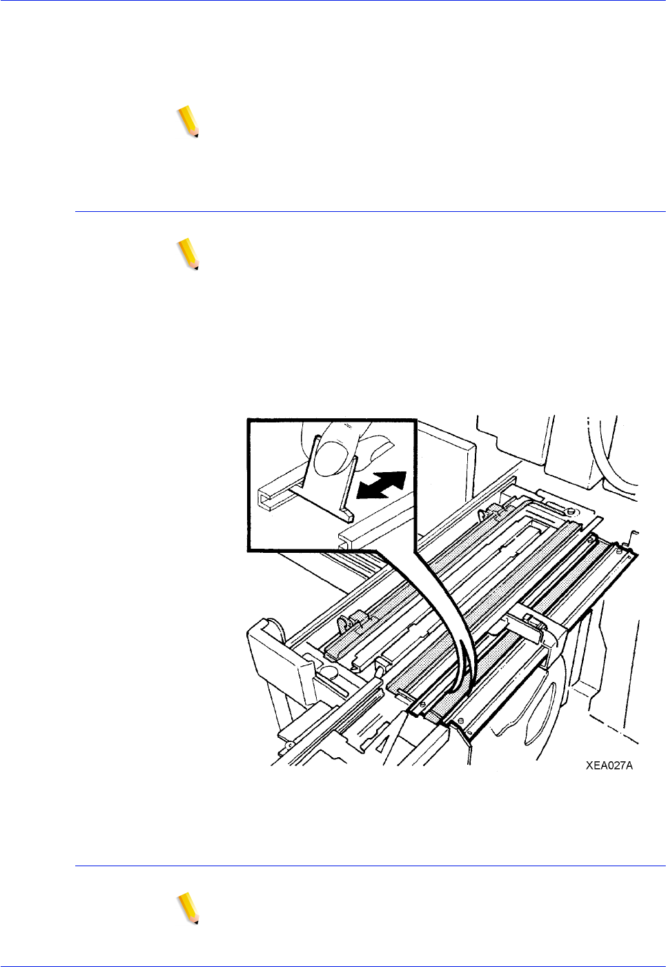
3-50 DocuTech 128/155/180 HighLight Color Operator Guide
Routine maintenance
end tab. Move the cleaner back and forth until the end tab
breaks.
d. Continue to move the cleaner in the same manner until the
2-sided tabs break.
NOTE: NOTE: Ensure that the following cleaning procedures are
performed in the order listed.
Cleaning the binder tape guides
NOTE: Production publisher configuration only
The following steps must be performed to clean the binder tape
guides.
1. Use the binder platen cleaner to clean the surfaces and
grooves of the tape guides.
2. Ensure that all the glue is removed from the grooves on the
tape guides.
Figure 3-48 Cleaning the tape guides
Cleaning the binder platen
NOTE: Production publisher configuration only
The following steps must be performed to clean the binder platen.
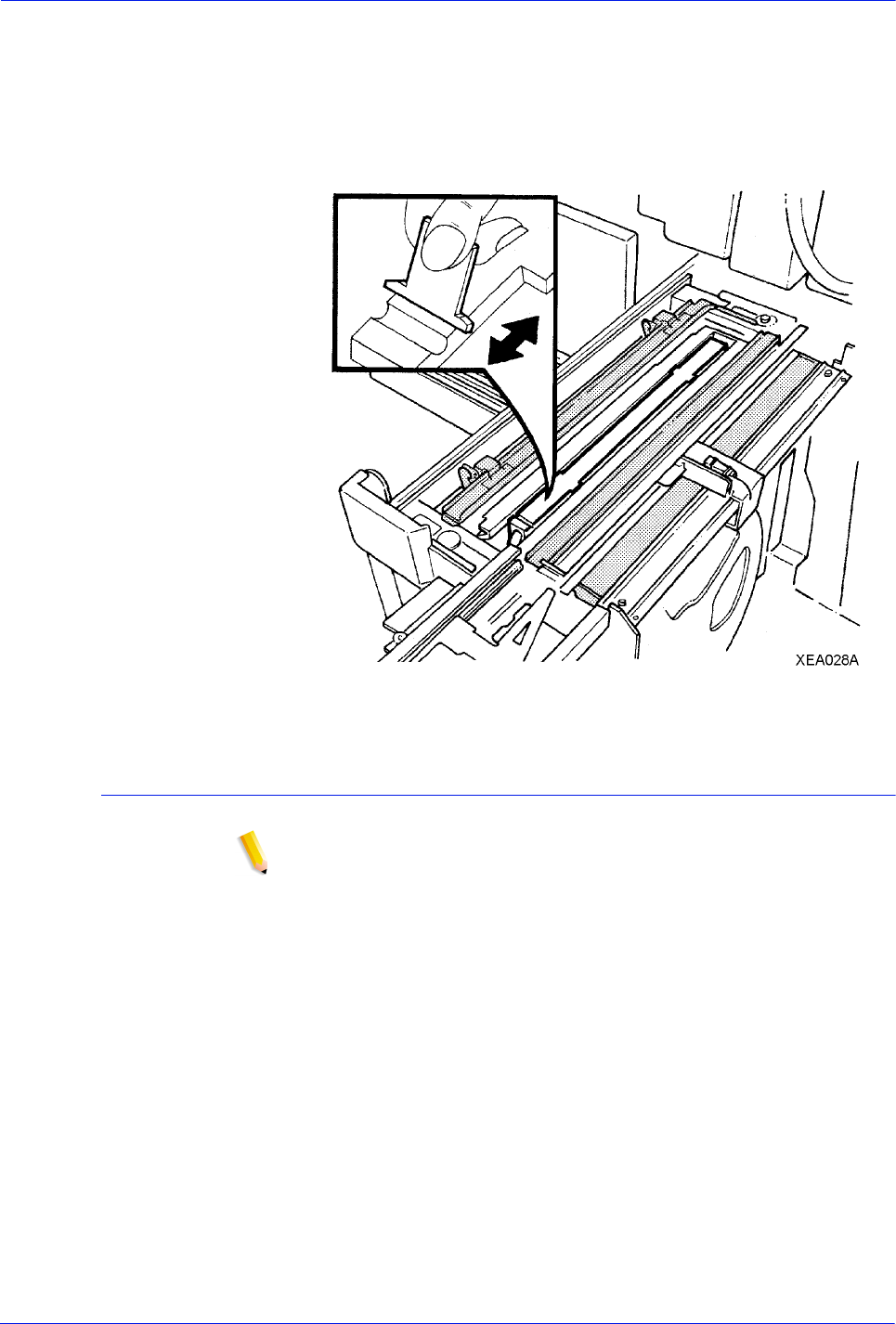
DocuTech 128/155/180 HighLight Color Operator Guide 3-51
Routine maintenance
1. Use the binder platen cleaner to clean the top and side
surfaces of the binder platen until all the glue is removed.
2. Ensure that the glue is removed from the grooves on the
binder platen surface, which align with the top and bottom
edges of the book.
Figure 3-49 Cleaning the binder platen
Cleaning the flappers
NOTE: Production publisher configuration only
Using the binder platen cleaner, clean the top and side surfaces of
the binder flappers until all the glue is removed.
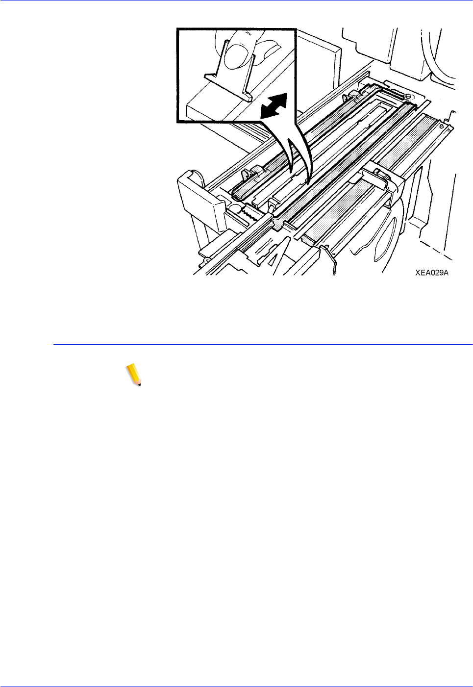
3-52 DocuTech 128/155/180 HighLight Color Operator Guide
Routine maintenance
Figure 3-50 Cleaning the flappers
Cleaning the calipers
NOTE: Production publisher configuration only
Using the binder platen cleaner, clean the binder caliper surfaces
until all the glue is removed.
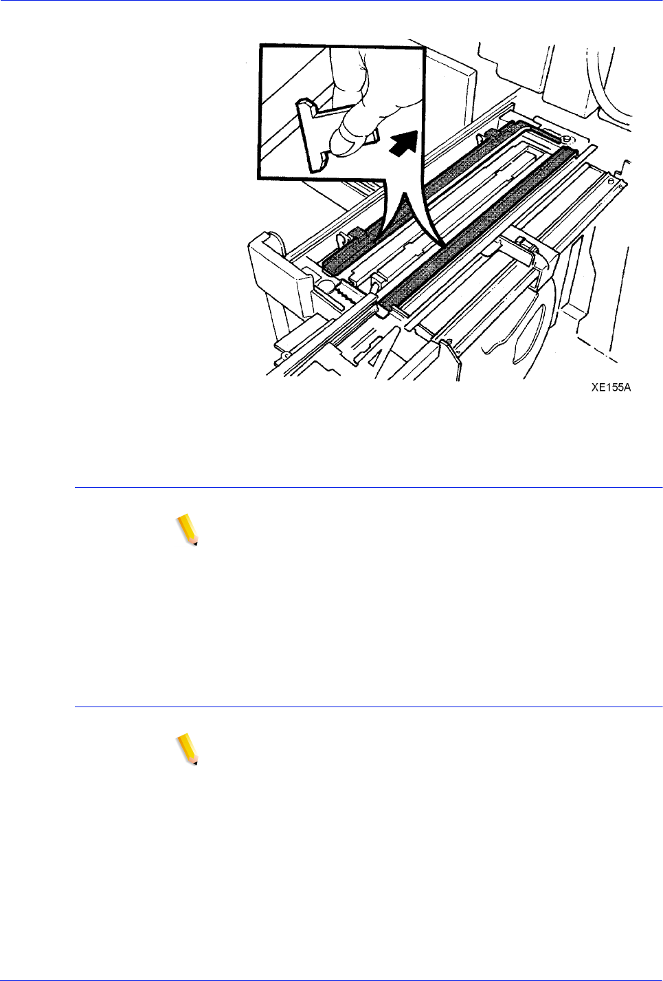
DocuTech 128/155/180 HighLight Color Operator Guide 3-53
Routine maintenance
Figure 3-51 Cleaning the calipers
Closing the binder
NOTE: Production publisher configuration only
Perform the following steps to close the binder.
1. Push in the binder drawer until it stops.
2. Close the finisher doors.
3. Place the platen cleaner in a safe place.
Replacing the stitcher spool A
NOTE: Production publisher configuration only
Use this procedure to replace stitcher spool A in the system.
Check stitcher spools A and B visually during the warm-up cycle.
Stitcher spool A is the spool on top, and stitcher spool B is the
spool on the bottom.
If spool B needs new wire, call the customer support center.
There is a label behind the stitcher panel that gives instructions for
replacing the stitcher spool A. Refer to this label if needed.
The following steps must be performed to replace the stitcher
spool A.
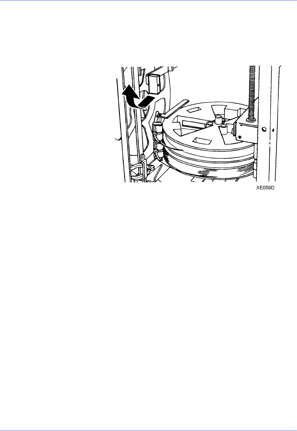
3-54 DocuTech 128/155/180 HighLight Color Operator Guide
Routine maintenance
1. Open the finisher doors.
2. Lift the stitcher panel, which is located directly above the
stitcher spools.
3. Pull the green stitcher head release handle forward and up
until it latches into place, as shown in figure 3-51.
Figure 3-52 Releasing the stitcher head
4. Remove the stitcher wire plug.
a. The stitcher wire plug is located above the binder area, as
shown in figure 3-52.
b. Press and hold down the release clip.
c. Pull the plug out of the stitcher head.
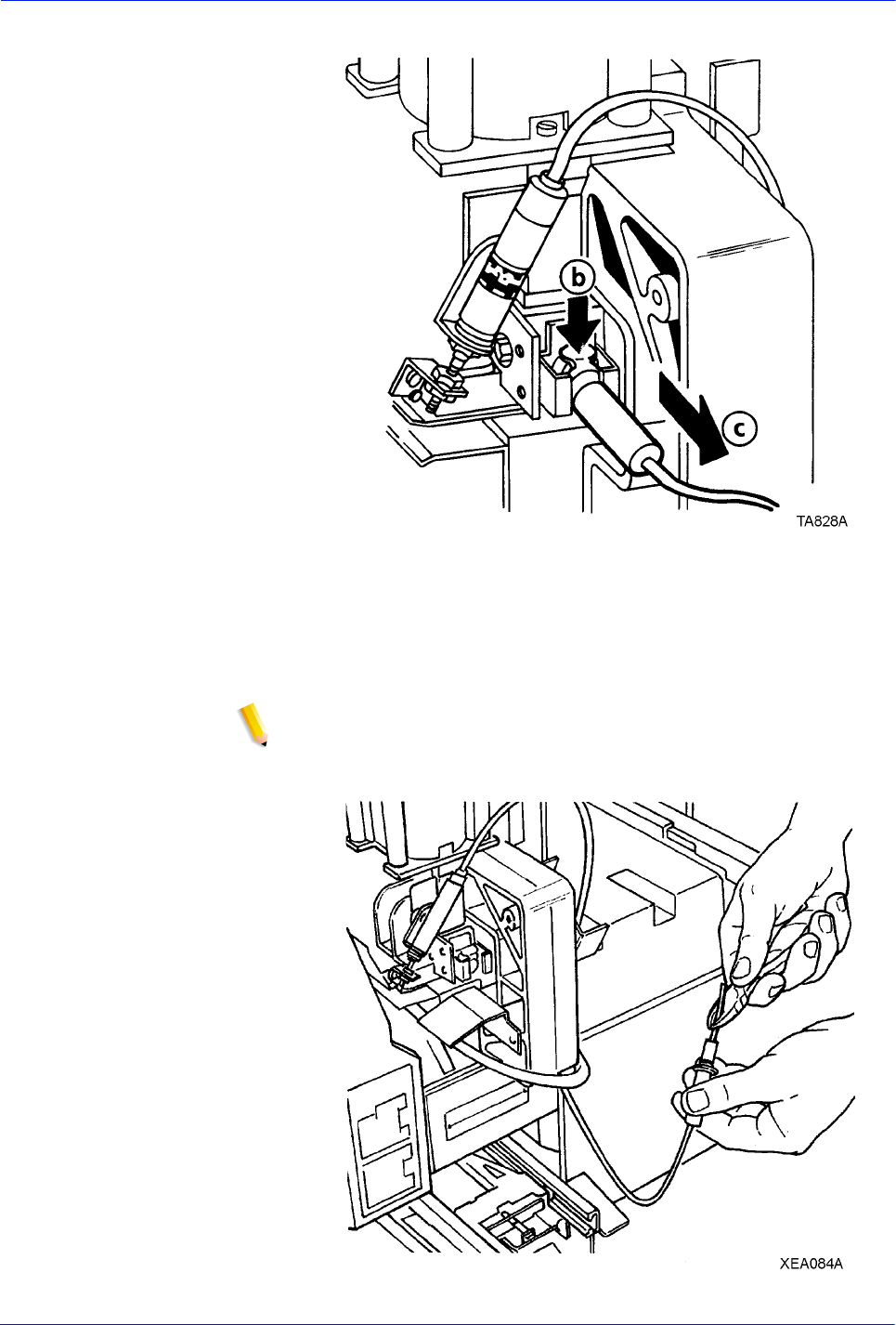
DocuTech 128/155/180 HighLight Color Operator Guide 3-55
Routine maintenance
Figure 3-53 Removing the stitcher wire plug
5. Perform one of the following steps:
• If there is no wire on the spool, use the wire cutters to pull
the remaining wire carefully out of the tubing, as shown in
figure 3-53.
NOTE: The wire cutter tool needed to perform this procedure
is located next to stitcher spool B.
Figure 3-54 Removing the wire from the tubing
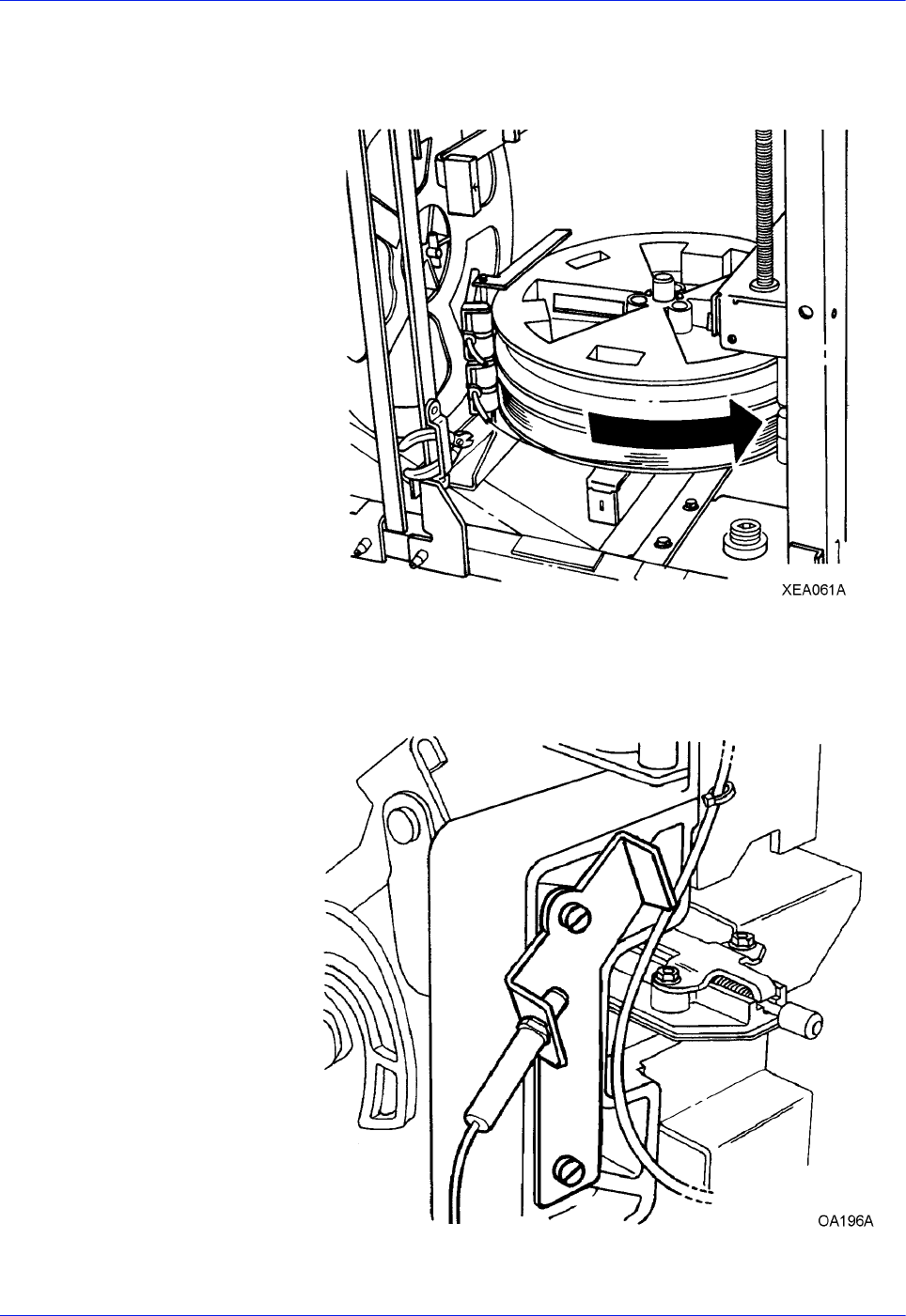
3-56 DocuTech 128/155/180 HighLight Color Operator Guide
Routine maintenance
• If there is wire on the spool, hold it on the spool and
carefully rewind the remaining wire out of the tubing and
onto the stitcher spool, as shown in figure 3-54.
Figure 3-55 Rewinding the remaining wire
6. Insert the plug into the measuring bracket, as shown in figure
3-55.
Figure 3-56 The measuring bracket
7. Release and remove stitcher spool A.
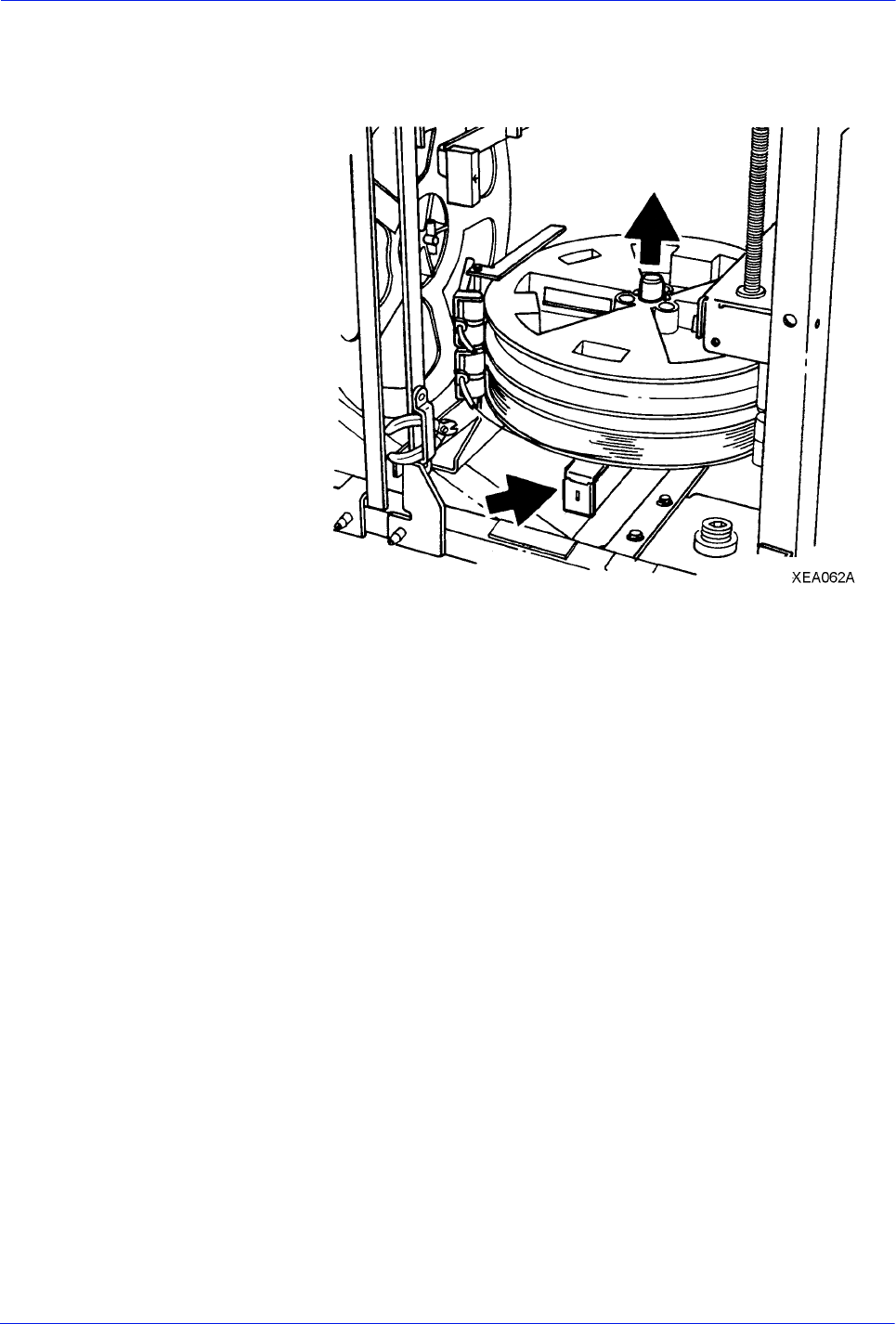
DocuTech 128/155/180 HighLight Color Operator Guide 3-57
Routine maintenance
a. Locate the green pin release handle under spool B, as
shown in figure 3-56.
Figure 3-57 Removing the stitcher spool pin
b. Pull and hold the handle forward and remove the pin.
c. Release the handle and remove stitcher spool A.
8. Install the new stitcher spool.
a. Slide the new stitcher spool into position with the paper
wrapper still in place.
b. Replace the stitcher spool pin. Push it down until it locks
into place, as shown in figure 3-57.
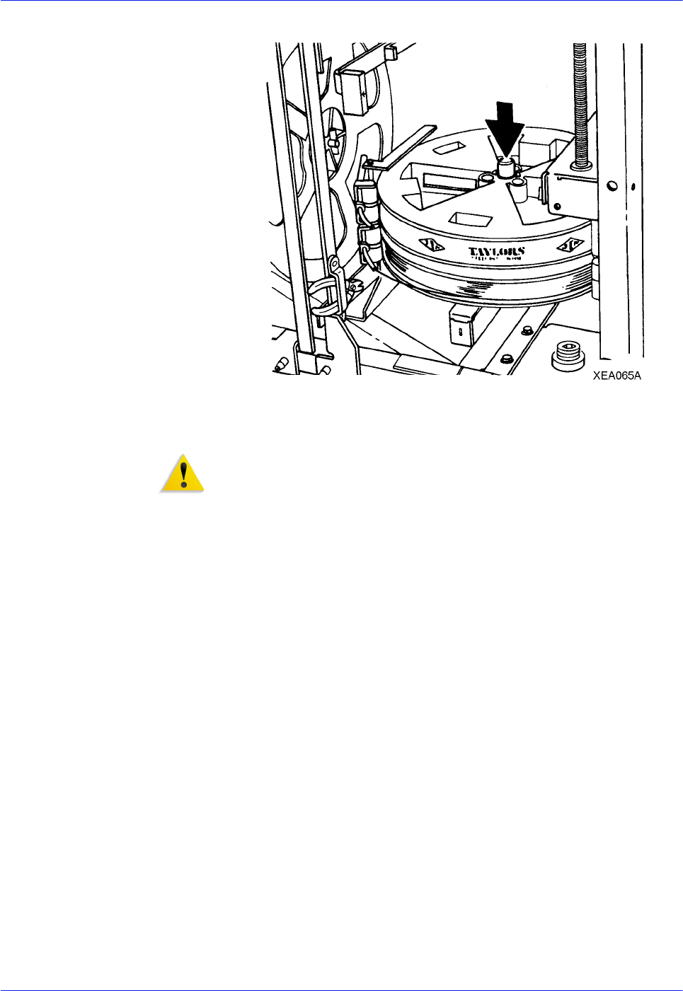
3-58 DocuTech 128/155/180 HighLight Color Operator Guide
Routine maintenance
Figure 3-58 Replacing the pin
9. Remove any damaged wire.
WARNING: Hold the wire on the spool to prevent eye injury and
to keep the wire from unwinding.
a. Locate the end of the wire on the new spool.
b. Using the wire cutters, carefully clip any bent or twisted
wire from the lead end of the wire.
c. Hold onto the end of the wire and carefully remove the
paper wrapper, as shown in figure 3-58.
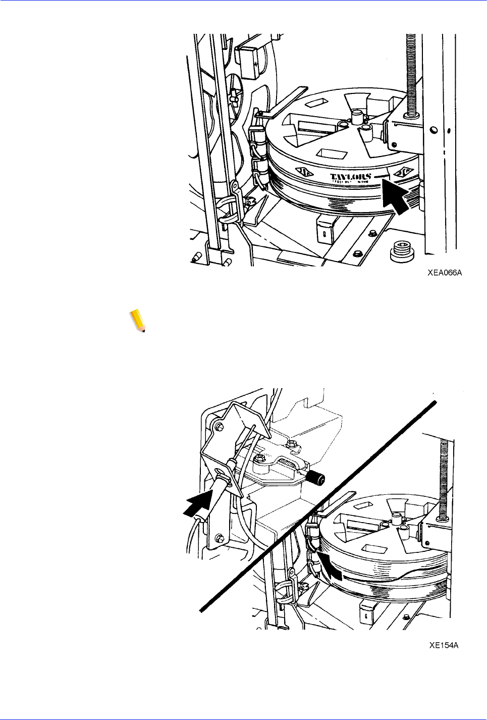
DocuTech 128/155/180 HighLight Color Operator Guide 3-59
Routine maintenance
Figure 3-59 Removing the paper wrapper
NOTE: Hold the wire between the thumb and forefinger of
both hands.
10. Feed the wire slowly into the tubing until the wire extends from
the stitcher plug, as shown in figure 3-59.
Figure 3-60 Feeding the wire
11. Remove the stitcher plug from the measuring bracket.

3-60 DocuTech 128/155/180 HighLight Color Operator Guide
Routine maintenance
12. Slowly and carefully pull about 3 feet (1 meter) of wire from the
spool.
13. Cut the wire, leaving about 2 inches (51mm) of wire extending
from the end of the stitcher plug.
14. Insert the plug into the measuring bracket.
15. Continue to feed the wire until it touches the back plate of the
measuring bracket.
16. Push the green stitcher head release handle down and back.
17. Pull the plug from the measuring bracket.
18. Insert the plug into the stitcher head until the plug snaps into
place.
19. Place the wire cutters in the storage bracket.
NOTE: Ensure that the wire cutters are not touching the
stitcher spools. This can prevent the stitcher wire from feeding
properly.
20. Lower the stitcher panel.
NOTE: Ensure that the stitcher panel has been lowered. The
stacker will not deliver prints if the stitcher panel is left in the up
position.
21. Close the finisher doors.
Storing the binder tape reels
NOTE: Production publisher configuration only
Binder tape contains paper that makes the tape sensitive to the
same conditions that affect paper, especially moisture. Figure 3-60
shows good storage conditions for the binder tape.

DocuTech 128/155/180 HighLight Color Operator Guide 3-61
Routine maintenance
Figure 3-61 Storing binder tape in a cool, dry place
Perform the following steps to store the binder tape wheels.
1. Always store binder tape in a dry place cooler than 90°F
(32°C).
2. Keep stored rolls in their original unopened containers.
3. Use rolls with older dates first. Save the original foil containers
for reuse in storing partially used rolls.
4. Place partially used rolls of binder tape in their original
resealable foil containers. Ensure that the edge is sealed
tightly.
Figure 3-62 Storing the binder tape
5. Store the partially used rolls of binder tape in a dry place
cooler than 90°F (32°C).

3-62 DocuTech 128/155/180 HighLight Color Operator Guide
Routine maintenance
Replacing the binder tape reel
NOTE: Production publisher configuration only
Use this procedure to replace the binder tape in the system.
To ensure proper binding and to reduce binder tape jams, do not
leave binder tape in the system when the binder is not in use.
If necessary, refer to the label on the binder for instructions on how
to replace the binder tape.
The following steps must be performed to replace the binder tape
wheel.
WARNING: All areas of the binder drawer, including the binder
tape, are hot, approximately 425°F (218°C), and may cause
serious burns. If the binder has been in a "Ready" condition, allow
the binder drawer to cool at least one hour before continuing the
procedure.
1. Open the finisher doors.
2. Grasp the green handle on the binder drawer and pull the
drawer out until it stops.
Figure 3-63 Opening the binder drawer
3. Remove the tape from the drive roll.
a. Lift the pressure roll release handle and remove the tape
from the drive roll.
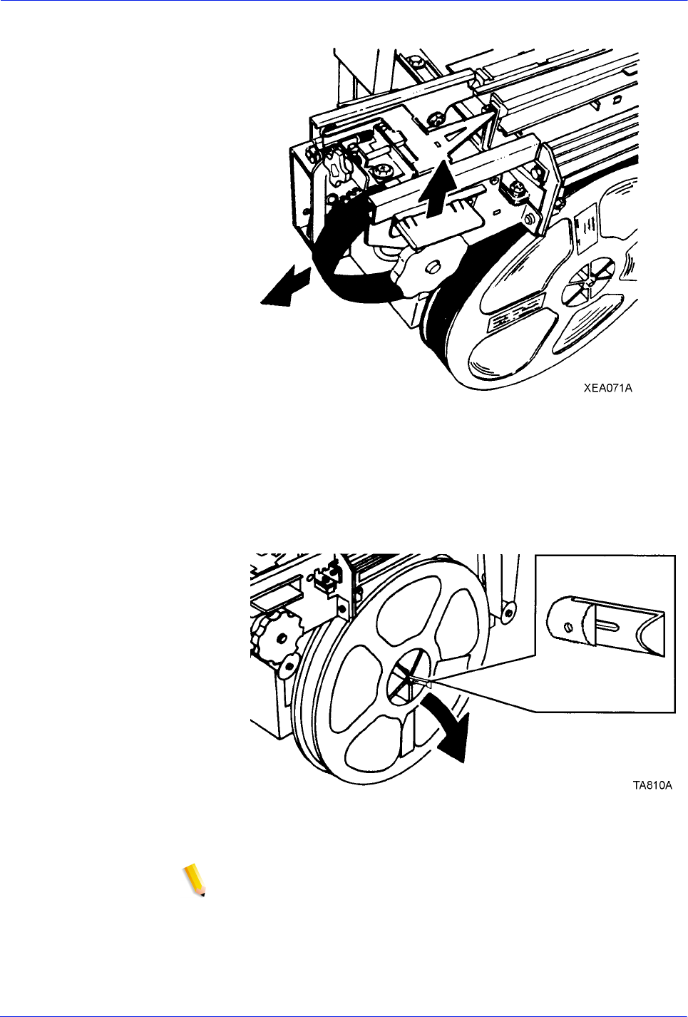
DocuTech 128/155/180 HighLight Color Operator Guide 3-63
Routine maintenance
Figure 3-64 Removing the tape
b. Rewind the tape onto the tape reel.
4. Slide the tape reel off the tape reel drive.
a. Move the reel retainer in the center of the reel to the
horizontal unlocked position.
Figure 3-65 Unlocking the reel
b. Remove the tape reel.
NOTE: Ensure that the larger center hole in the reel faces the
drive.
5. Slide the new tape reel onto the tape reel drive.
a. If necessary, rotate the tape reel slightly until it clicks into
position.
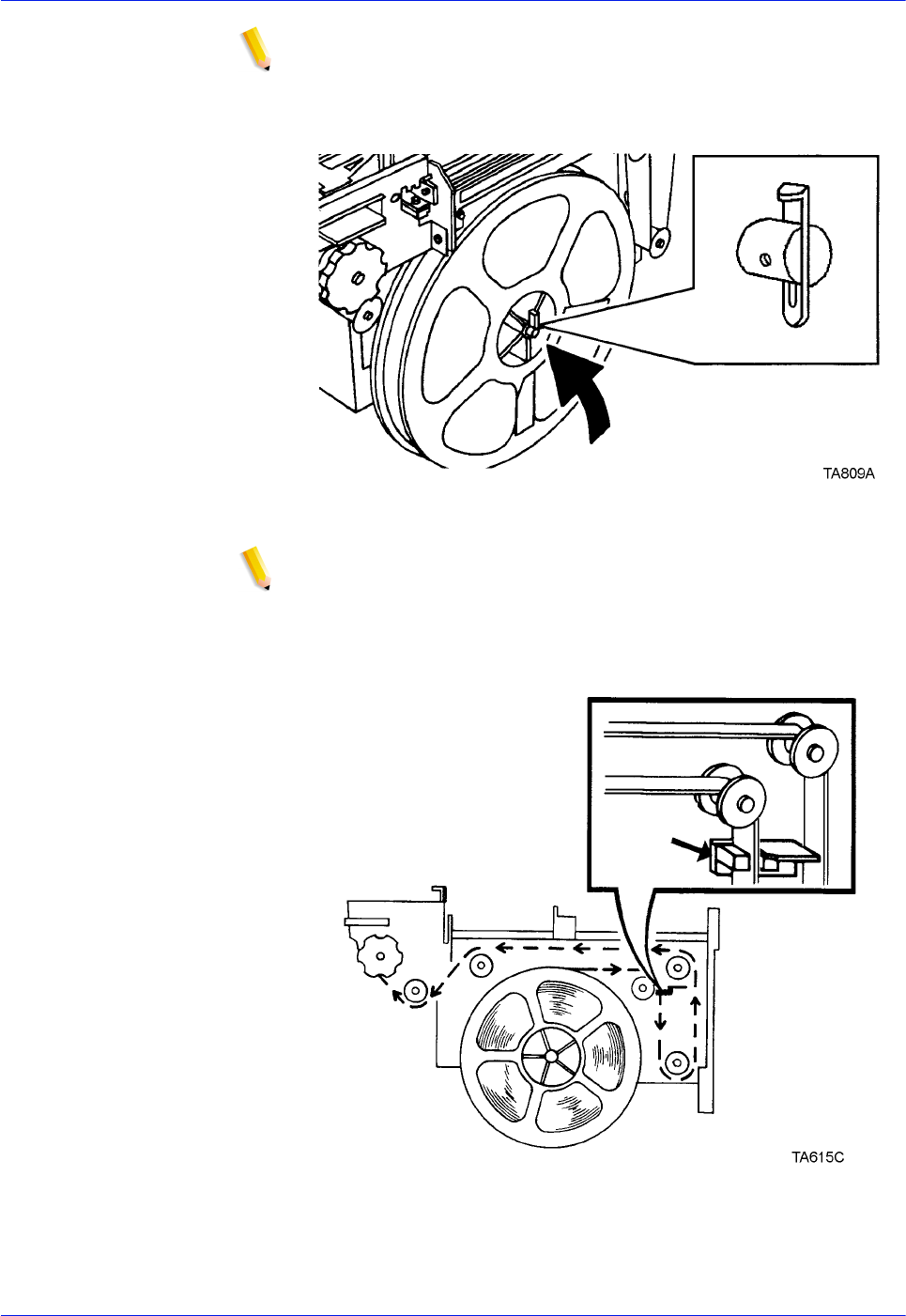
3-64 DocuTech 128/155/180 HighLight Color Operator Guide
Routine maintenance
NOTE: NOTE: The tape will not feed properly if the retainer is not
locked.
b. Move the reel retainer to the locked position.
Figure 3-66 Locking the reel
NOTE: NOTE: Ensure that the tape passes through the binder tape
sensor.
6. Follow the instructions on the binder tape loading label and
thread the tape through the tape feeder.
Figure 3-67 Threading the tape through the tape feeder
7. Thread the tape around the drive roll to the edge of the
pressure roll.
Tape
Sensor

DocuTech 128/155/180 HighLight Color Operator Guide 3-65
Routine maintenance
Figure 3-68 Threading the tape to the pressure roll
8. Turn the green knob clockwise until the tape extends at least 2
inches (51mm) beyond the tape guides.
Figure 3-69 Feeding the tape manually
9. Cut the tape.
a. Lift up on the green tape cutter handle, as shown in figure
3-69.
b. Remove the cut piece of tape.
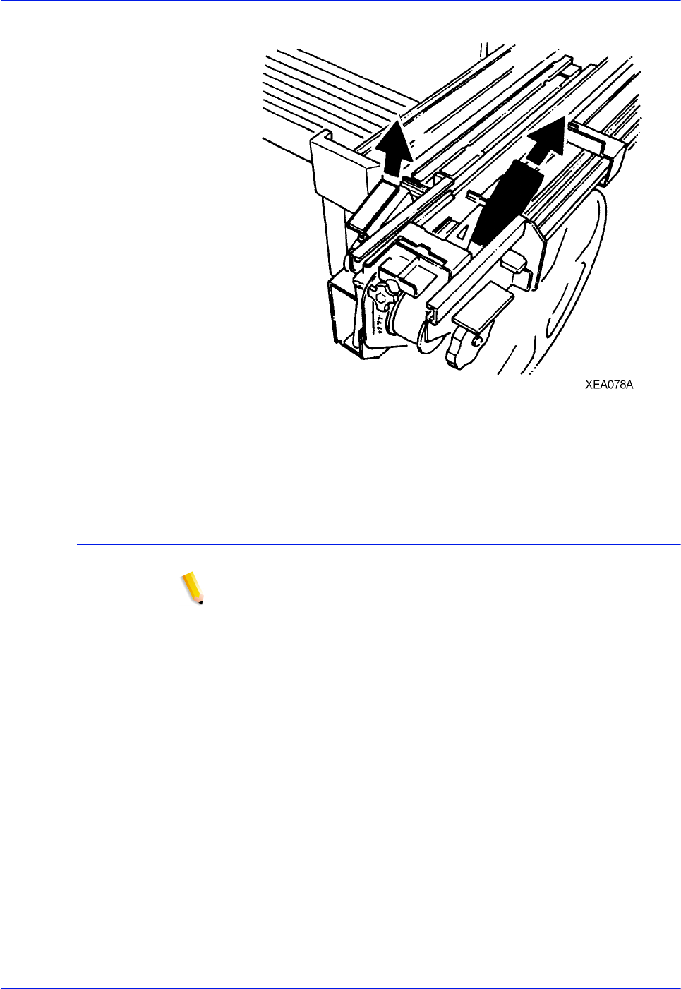
3-66 DocuTech 128/155/180 HighLight Color Operator Guide
Routine maintenance
Figure 3-70 Cutting the tape
10. Close the binder drawer.
11. Close the finisher doors.
Adjusting the binder tape registration
NOTE: Production publisher configuration only
The binder tape knob is used to align the registration of the binder
tape to the top edge of a bound book.
This procedure has no effect on the length of the tape, but you
should perform this procedure before adjusting the tape length.
To adjust the length, refer to the on-line help.
Perform the following steps to adjust the binder tape registration.
1. Ensure that the tape guides are clean and free of glue residue.
Refer to the procedure, "Cleaning the binder," in this section.
2. Determine the adjustment amount for the top edge of the
book.
3. Open the finisher doors.
4. Measure the distance between the top of the binder tape and
the top of the book.
5. Locate the black binder tape knob on the front of the binder
drawer.
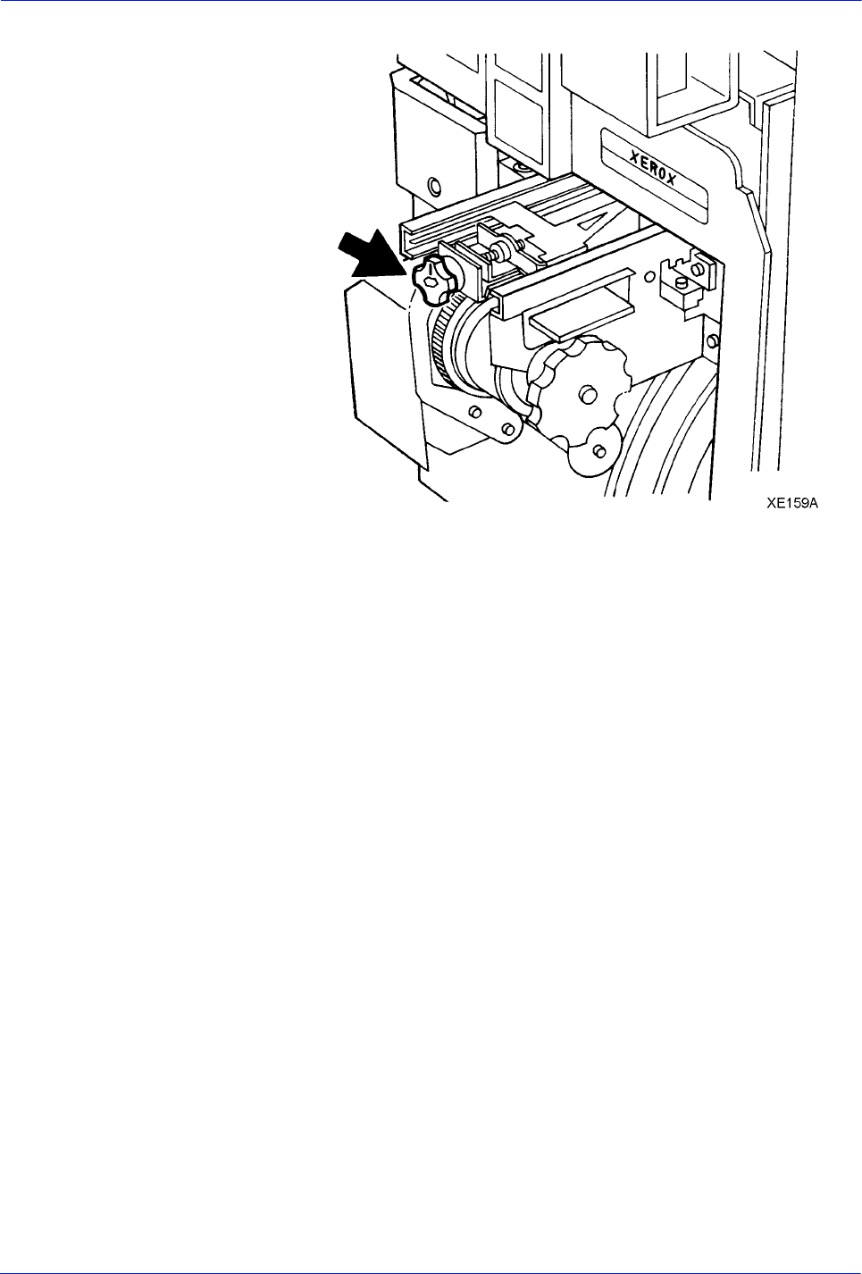
DocuTech 128/155/180 HighLight Color Operator Guide 3-67
Routine maintenance
Figure 3-71 Locating the binder tape knob
The knob is spring loaded and moves in increments to change
the location of the binder tape. Each increment equals a
change of 0.1mm, up or down, on the edge of the book. One
full rotation of the knob is equal to 0.04 inch (1mm).
6. Pull the knob toward you to rotate it for the adjustment.
7. Adjust the tape position by performing one of the following
steps:
• Pull the knob and rotate it clockwise to move the tape
toward the top edge of the book, as shown in figure 3-71.
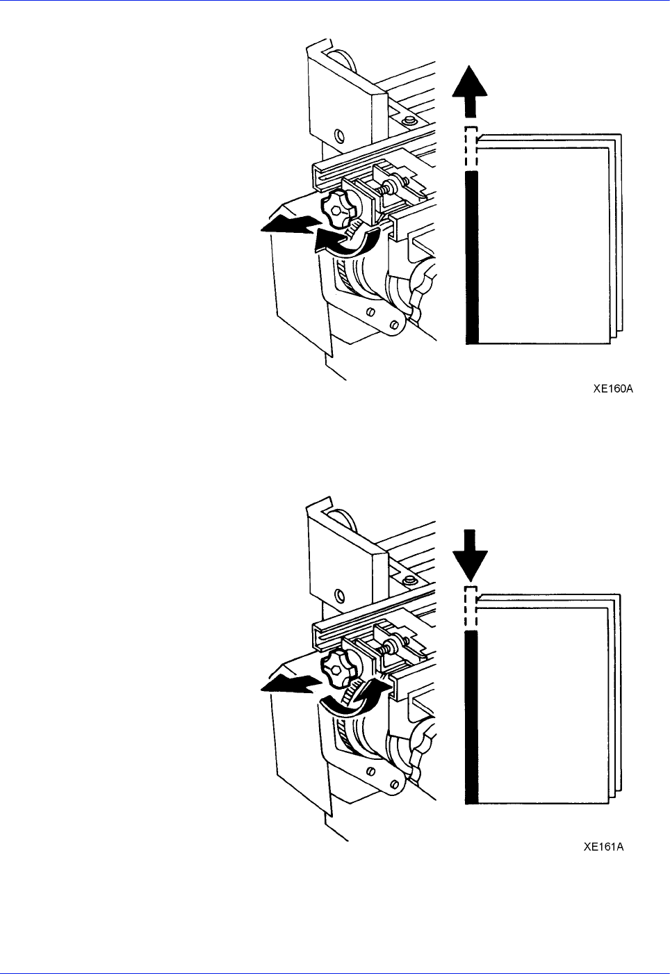
3-68 DocuTech 128/155/180 HighLight Color Operator Guide
Routine maintenance
Figure 3-72 Adjusting the tape position up
• Pull the knob and rotate it counterclockwise to move the
tape toward the bottom edge of the book.
Figure 3-73 Adjusting the tape position down
8. Close the finisher doors.
9. Run a test binder job to check your adjustment.
10. Perform the procedure again as needed.
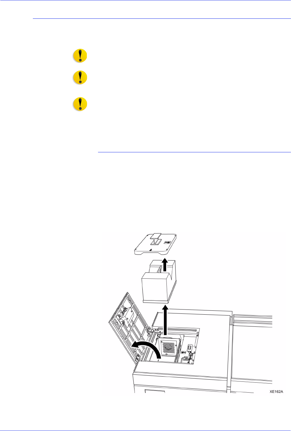
DocuTech 128/155/180 HighLight Color Operator Guide 3-69
Routine maintenance
Replacing the Customer Replaceable Filter
When directed by the screen message P09-447, HLC Waste Dry
Ink Filter full, call for service or replace the waste dry ink filter.
CAUTION: To prevent dry ink spills, remove the waste dry ink
filter only when directed to do so by a message on the screen.
CAUTION: Do not use warm or hot water, or general cleaning
solvents to remove dry ink from your skin or clothing. The heat or
solvent will set the dry ink and make it difficult to remove.
CAUTION: If any dry ink should get on your clothes, brushing
with a dry paper towel or a stiff-bristled brush may remove the ink.
If not, launder your clothes with detergent and cold water. Tell a
commercial dry cleaner that the spot is dry ink or "toner" so that
they will not use a solvent that will set the dry ink stain.
Replace the waste dry ink filter
The following steps must be performed to replace the waste dry
ink filter:
1. Ensure that the printer has stopped printing.
2. Obtain a new filter. Open the box and remove filter from the
bag and set aside.
3. Set a piece of paper larger than the filter on the top cover to
the right of the Highlight Color module.
4. Open the top cover of the Highlight Color module.
Figure 3-74 Opening the cover and removing the filter
5. Unsnap the 4 clips on top of the waste dry ink filter housing.
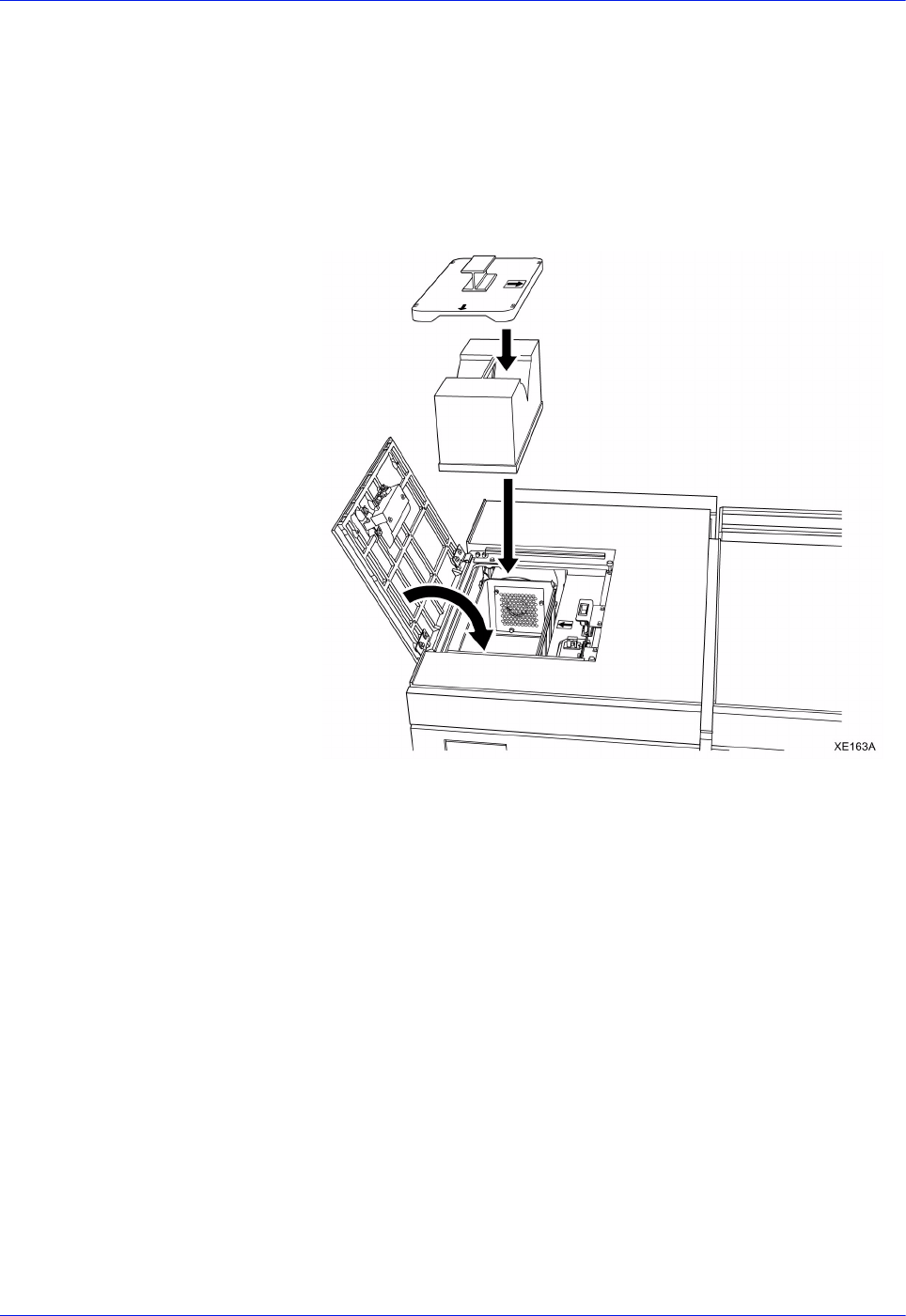
3-70 DocuTech 128/155/180 HighLight Color Operator Guide
Routine maintenance
6. Remove the filter housing cover and set it on the piece of
paper from step 3.
7. Remove the filter by pulling straight up with the handle.
Immediately place the filter in the empty bag that contained the
new filter.
8. Place the used filter into the box that contained the new filter.
9. Insert the new filter into the filter housing. Firmly press straight
down. The filter clicks into place.
Figure 3-75 Inserting the new filter and closing the cover
10. Replace the filter housing cover. Ensure that the yellow arrows
align with each other.
11. Snap the 4 clips back into the latched position.
12. Close the top cover.
13. Discard the old filter appropriately. It is not recyclable.

DocuTech 128/155/180 HighLight Color Operator Guide 4-1
4 Problem Solving
The system is designed to help you find and solve problems as
they happen. The system detects hardware and software
problems, displays error or fault messages and screens, and
sounds an alert tone (if it is enabled) when a problem needs to be
corrected.
This section of the operator guide describes how the system
informs you of problems. When you know there is a system
problem, you can take measures suggested by the system to
correct the problem. You can also use the problem and solution
tables in this section to resolve recurring problems. Included are
detailed procedures that are required to resolve some of the
problems.
If you are not able to correct a problem, or you have a question
about system operation, you should call the Customer Support
Center. If a customer support representative cannot solve your
problem over the phone, a service representative will be
dispatched.
How problems are displayed
Hardware problems show themselves by way of messages,
document misfeeds, paper jams, poor prints, fault codes, and
system components that do not operate correctly.
Software problems usually show up as messages in the status
area of the screen or as fault codes on the fault frames. Some
software problems affect hardware behavior. For example, the
printer may operate without producing any prints. This is a
condition called "dead cycling."
Printer faults and fault windows
When the printer needs attention, it is called a fault. There are
three types of faults: those that require immediate attention, those
that provide information, and those that require service.
Examples of faults that would require immediate attention are
misfeeds in the paper path or paper jams.
Examples of a fault that is informational is low dry ink. If this type
of fault is not resolved, a fault requiring immediate attention will
result eventually.
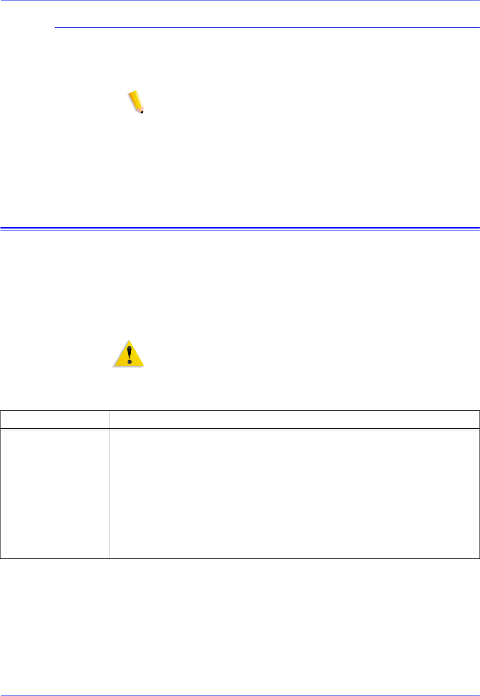
4-2 DocuTech 128/155/180 HighLight Color Operator Guide
Problem Solving
When a fault occurs
When a fault occurs in the printer an indicator appears on the
FreeFlow Print Server Print Services window and a Printer Faults
message appears.
NOTE: The printers also have an attention light on top of the
finisher module. A flashing light indicates a fault requiring
immediate attention; a steady light indicates a fault that can be
cleared at a later time.
Refer to the on-line help or System Guide for additional
information on printer faults.
Resolving a processor problem
If you have a recurring processor problem, perform the following
activities:
• Find the problem in the Problem column of the problem solving
charts below.
• Follow the instructions in the Suggested solutions column of
the problem solving charts in this guide.
WARNING: Remember that the fuser and binder area surfaces
are hot. Proceed with caution when clearing all jams.
Table 4-1. Resolving a processor problem
Problem Suggested Solution
Paper tray elevator
fails to rise or lower
• Ensure that the stock is loaded properly in the paper trays, with the rear
and side guides against the stock stack.
• If the elevator fails to rise or lower in paper tray 1 or 2, latch the paper
feeder by pressing down on the green dot inside the tray.
• Do not slam the trays closed. Push the trays in slowly but firmly.
• Ensure that all misfed stock has been removed from the immediate
area of the paper trays.

DocuTech 128/155/180 HighLight Color Operator Guide 4-3
Problem Solving
Paper path jams • Check the area where the jams are occurring to ensure that the paper
path is clear of paper and other obstructions.
• If a jammed sheet of paper tears when being removed, ensure that you
have removed all of the sheet pieces.
• Ensure that the paper path baffles are in the correct seated position.
• Ensure that the stock is loaded properly in the trays, with the rear and
side guides against the stack.
• Ensure that the stock is not loaded above the bottom of the red line in
the paper tray.
• Ensure that the stock has no bent corners, or tears, and that the edges
are straight. Remove any damaged sheets.
• Repeated jamming may be due to a paper curl problem that can be
resolved by adjusting the decurler lever. Refer to the procedure,
"Adjusting for paper curl," in this guide.
• Paper weight less than substance 20 (75 g/m2) will require careful
setting of the decurler. Refer to the procedure, "Adjusting for paper
curl," in this guide.
• Fan the stock thoroughly.
• Ensure that the stock is within the limitations described in the
satisfaction guides in the "Technical information" chapter.
• Paper weight less than substance 20 (75 g/m2) will require careful
storage and handling. Refer to the "Technical information" chapter.
Paper misfeeds and
multifeeds
• Ensure that the stock is loaded properly in the paper trays, with the rear
and side guides against the stack.
• Ensure that the stock is not loaded above the bottom of the red line in
the paper tray.
• Ensure that the stock has no bent corners, or tears, and that the edges
are straight. Remove any damaged sheets.
• Check the sheets in the bottom of the paper tray for damage. If they are
damaged, discard the sheets.
• Ensure that the stock to be fed out of the paper tray is not excessively
curled. Refer to the procedure, "Adjusting for paper curl," in this guide.
• If the misfeeds are occurring in the paper tray, ensure that the paper
feeder is latched by pressing down on the green dot inside the tray.
• Fan the stock at all four corners. Change it if it has uneven edges or if it
was not drilled properly.
• The stock should be kept in the original wrapper and stored correctly.
Refer to the "Technical information" chapter.
• Ensure that the stock is within the limits described in the "Technical
information" chapter.
Problem Suggested Solution

4-4 DocuTech 128/155/180 HighLight Color Operator Guide
Problem Solving
Missing sheets in a
set immediately after
a jam.
After recovering from a jam, an incomplete set may be purged and the set
reprinted. Check the prints to ensure that you are not confusing the purged
output with the completed set.
Printer is dead
cycling; it is running,
but not making any
prints
If the printer is running, but not making any prints, and no message is
displayed on the screen, open a processor door to stop the printer. If this
problem repeats, refer to the procedure, "Calling for assistance," in this
guide.
Fuser jams WARNING: The fuser surfaces are hot. To avoid injury, proceed with
caution when removing all jams. Use a piece of paper to remove jammed
sheets from the fuser.
The jammed sheets in the fuser require careful handling because they may
not be fused properly.
Images that extend all the way to the edge of the prints may cause
increased frequency of jams.
• Do not place dense images to be printed at the right or left lead and trail
edges of the paper. This may cause fuser jams.
• If the above adjustment does not resolve the problem, contact the Site
Administrator to access the Lead Edge Screening feature on the Printer
Switches window.
There are three settings available in the Lead Edge Screening feature:
• Use the Off setting when it is necessary to print all of the document.
• Use the Standard setting when the documents have narrow black lines
or no dark areas on the lead edge. This is the system default setting
and is the recommended setting.
• Use the Stress setting when the system is experiencing fuser jams and
the Standard option is selected.
• Use the Erase All Edges setting when the system is experiencing jams
and the image prints to the edges of the paper.
Holes are on the
wrong side of the
prints
Ensure that the stock is loaded correctly. Refer to the label on the tray.
Paper curl Adjust the decurler. Refer to the procedure, "Adjusting for paper curl," in this
guide.
Fault Code P09-418 If this fault is persistent, replace the wire module. If the fault continues, call
for service. Refer to the wire module removal and replacement procedure in
this guide.
Fault Code P09-447 When this fault is appears, call for service or replace the waste dry ink filter.
Refer to the customer replaceable waste filter procedure in this guide.
Fault Code P10-216 This is a printer problem. Switch the printer off and on. Allow a minimum of
30 seconds between switching the printer off and switching the printer back
on.
Problem Suggested Solution

DocuTech 128/155/180 HighLight Color Operator Guide 4-5
Problem Solving
Processor power is
off unexpectedly
The processor or the FreeFlow Print Server may have an electrical
problem. If the FreeFlow Print Server has an electrical problem, it may shut
off the power to the processor.
1. Determine if the FreeFlow Print Server power and the processor power
are off.
• If the print server's screen is blank and the power-indicator light is
not blinking, the print server power is off. Refer to the System Guide
• If the paper tray lights are out, the power to the processor is off.
Proceed with step 2.
2. Determine if the processor has a ground fault protector. If there is not a
ground fault protector installed, refer to the procedure "Calling for
assistance," in this guide.
3. If the processor has a ground fault protector, determine whether the
protector has shut off the power.
• If the red light is visible on the protector, proceed with step 4.
• If the red light is not visible, something other than the protector has
shut off the power. Refer to the problem "Processor power is off
unexpectedly, and the ground fault protector did not trip," in this
section.
4. Press the reset button on the processor ground fault protector.
• If the red light switches off, proceed with step 5.
• If the red light does not switch off, or immediately switches on again,
refer to the procedure, "Calling for assistance", in this guide.
5. Switch the white-handled circuit breakers near the protector to the on
(up) position.
• If the power comes on, proceed with step 6.
• If the circuit breakers immediately switch off again, refer to the
procedure, "Calling for assistance,"in this guide.
6. Select the Reset icon on the fault frame. This should clear the fault.
7. Clear any other faults that may be declared. Do not clear the paper path
unless directed to do so. The system will maintain job integrity.
8. If the power repeatedly switches off unexpectedly, refer to the
procedure, "Calling for assistance," in this guide.
Processor power is
off unexpectedly,
and the ground fault
protector did not trip
1. Select the Reset icon on the fault frame.
2. Call for maintenance or electrical assistance within your facility in order
to determine whether power is available at the electrical panel box
within your facility.
3. Do not clear the paper path unless directed to do so. The system will
maintain job integrity.
Problem Suggested Solution

4-6 DocuTech 128/155/180 HighLight Color Operator Guide
Problem Solving
Solving print quality problems
A print quality problem means that the job was submitted
successfully, but does not print correctly.
NOTE: If the Image Quality parameters are changed, you must
restart or reboot the FreeFlow Print Server software in order for
the changes to take affect.
NOTE: The image quality default settings are optimized for the
printer. If changes have been made, you can restore the factory
installed defaults by selecting [Defaults]. Selecting [Reset] sets the
image quality parameters to the most recently applied setting.
Clearing paper jams
The paper path is the route that materials (paper, transparencies,
labels, and so on) follow through the printer from the feeder trays
to the stacker bins, sample tray, or purge tray. Paper jams can
occur at any stage of the paper path. After a paper jam the printer
stops, and the following happens:
• If enabled, the Attention light flashes.
• Messages appear on the print server informing you of the
paper jam and its location in the printer.
• Selecting the message displays a printer mimic graphic that
shows the area of a paper jam and lists instructions for
clearing the jam.
NOTE: It is important that you clear the sheets only in the areas
indicated on the print server.
Checking job integrity following a paper jam
When printing resumes following a paper jam, there is a slight
possibility that duplicate sheets may be printed or sheets may be
missing from a job. For that reason, you should check job integrity
after the job has been printed.
1. The printer offsets the first sheet printed following a paper jam.
Locate that sheet in the stack.
2. Check the sheets immediately before and after the offset sheet
to see if there are any missing or duplicate sheets in the
output.
NOTE: A message may appear on the print server screen telling
you that there is a suspected page delivery error and advising you
to check the output.
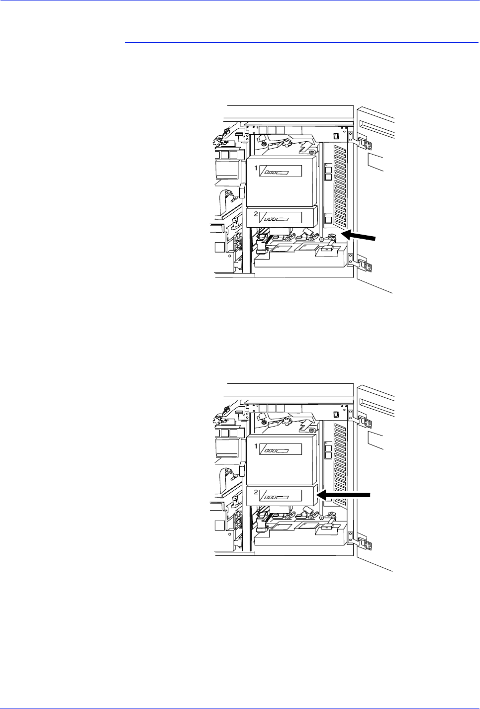
DocuTech 128/155/180 HighLight Color Operator Guide 4-7
Problem Solving
Clearing paper jams in printer areas 2 through 10 for both
configurations
In the following figures, the printer jam clearance areas have
arrows pointing to them or circles drawn around them.
Figure 4-1 Area 2
Figure 4-2 Area 3

4-8 DocuTech 128/155/180 HighLight Color Operator Guide
Problem Solving
Figure 4-3 Area 4
Figure 4-4 Area 5
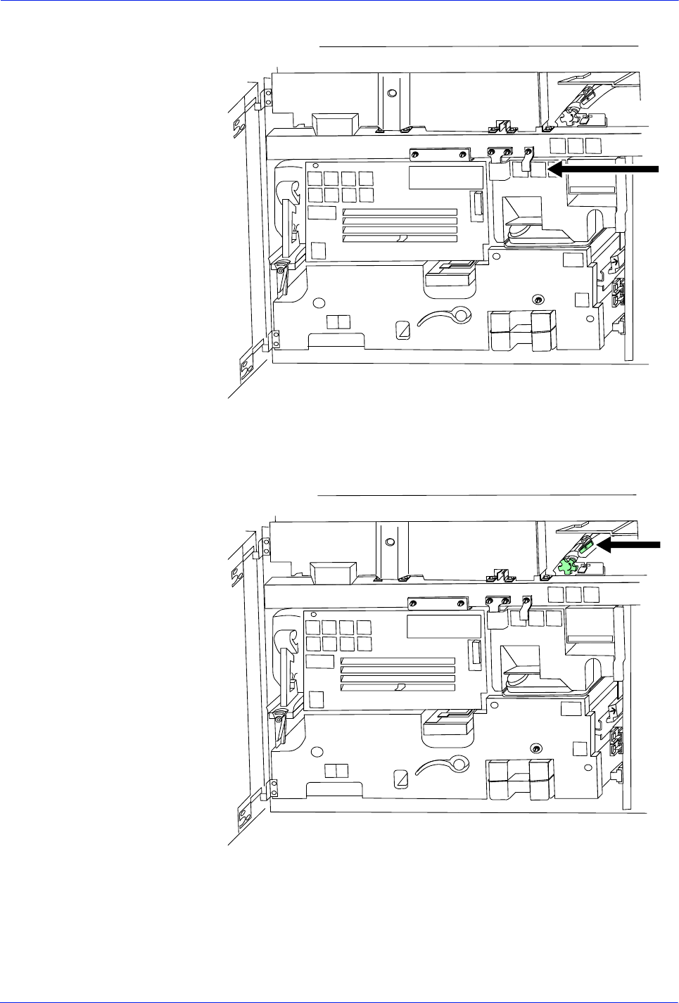
DocuTech 128/155/180 HighLight Color Operator Guide 4-9
Problem Solving
Figure 4-5 Area 6
Figure 4-6 Area 7
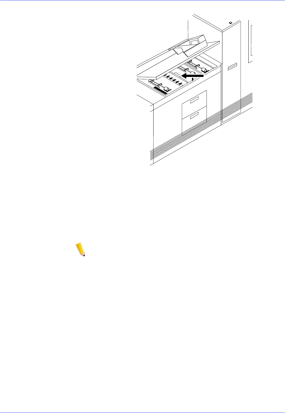
4-10 DocuTech 128/155/180 HighLight Color Operator Guide
Problem Solving
Figure 4-7 Area 8
NOTE: If a jammed sheet rips as you are removing it from area 8,
you may have to use the pinch lever in area 9 to remove the
paper. Refer to the Note following the area 14 figure for additional
instructions.
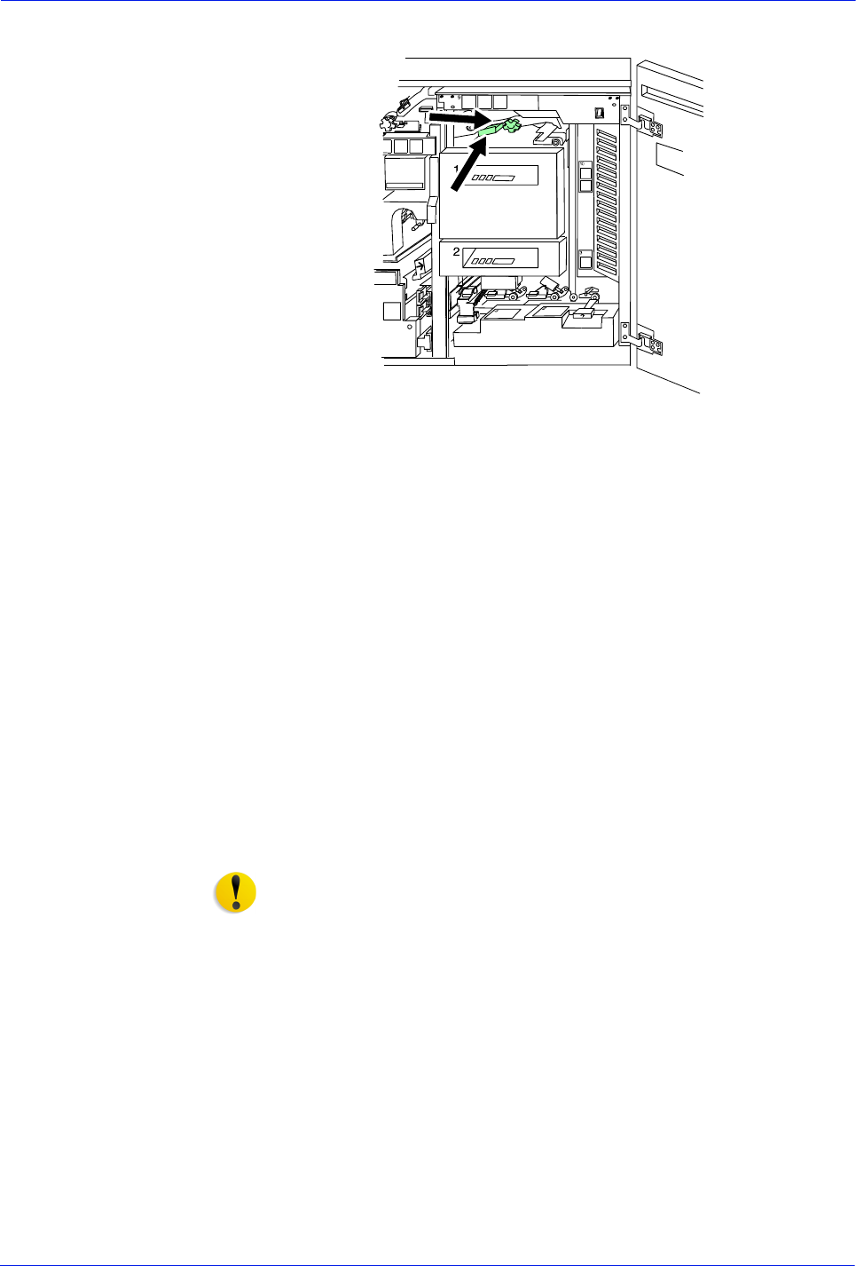
DocuTech 128/155/180 HighLight Color Operator Guide 4-11
Problem Solving
Figure 4-8 Area 9
To clear jams from area 9:
1. Lower and pull out tray 1 to give you better access to area 9.
2. Pull the area 9 green lever toward you to unlatch it. Be sure to
relatch the lever after you have cleared any paper in this area.
To further facilitate removing sheets wedged in this area, pull
out tray 1 and hold the green lever down.
3. Turn the green knob located to the right of the lever to move
jammed sheets further along the paper path to where they are
more accessible and easier to remove.
4. If paper rips as you are removing it from area 9, or if you have
difficulty removing paper from this area, use the pinch lever
located further inside area 9. Paper may be caught in this area
during duplex printing.
CAUTION: This area of the printer may be hot. Be careful when
inserting your hand.
Using the pinch
lever to access area
9
To use the pinch lever located inside area 9:
1. Locate the green pinch lever directly behind area 9 (above the
green knob and further inside area 9).
2. Carefully reaching your hand into the area, squeeze the edges
of the pinch lever and lift it up.
3. Remove any paper caught in this area.
4. Turn the green pinch lever to its original position. Make sure
that you relatch the lever after you have cleared any paper in
this area.
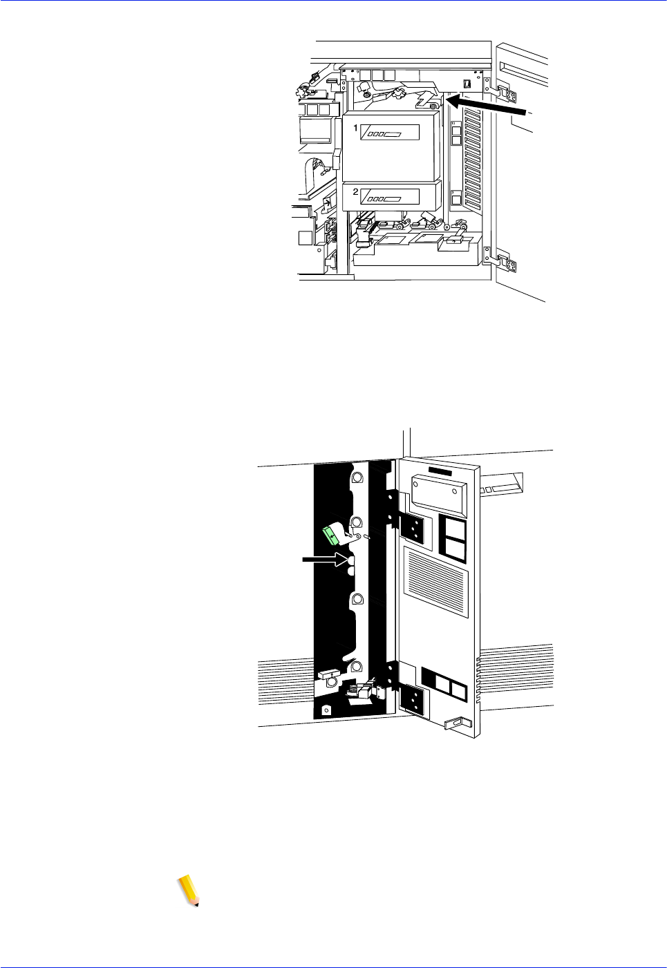
4-12 DocuTech 128/155/180 HighLight Color Operator Guide
Problem Solving
Figure 4-9 Area 10
Figure 4-10 Area 11 (all feeder/stackers)
NOTE: High volume printer configuration only
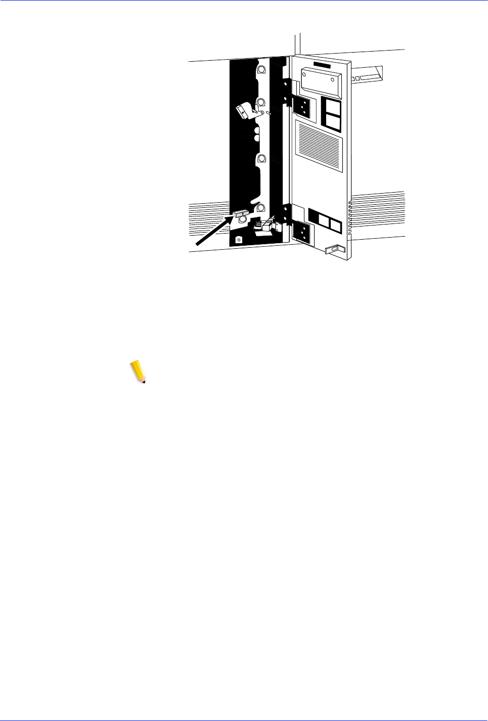
DocuTech 128/155/180 HighLight Color Operator Guide 4-13
Problem Solving
Figure 4-11 Area 12 (all feeder/stackers)
NOTE: High volume printer configuration only
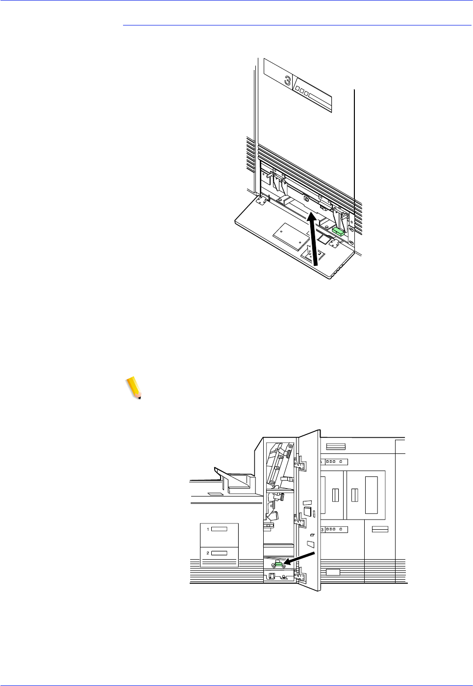
4-14 DocuTech 128/155/180 HighLight Color Operator Guide
Problem Solving
Clearing paper jams in the Feeder/Stackers
Figure 4-12 Area 13
NOTE: Figures 4-12 and 4-13 applicable on the high volume
printer configuration only.
Figure 4-13 Area 14
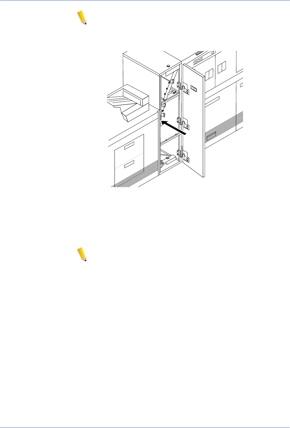
DocuTech 128/155/180 HighLight Color Operator Guide 4-15
Problem Solving
NOTE: You may sometimes find paper lying on top of area 14,
even though there is no message indicating a jam in this area.
Discard the paper.
Figure 4-14 Area 15
NOTE: High volume printer configuration only
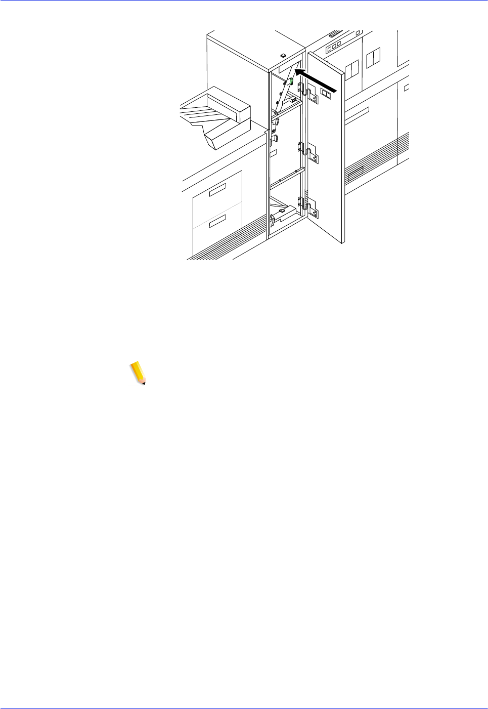
4-16 DocuTech 128/155/180 HighLight Color Operator Guide
Problem Solving
Figure 4-15 Area 16
NOTE: High volume printer configuration only
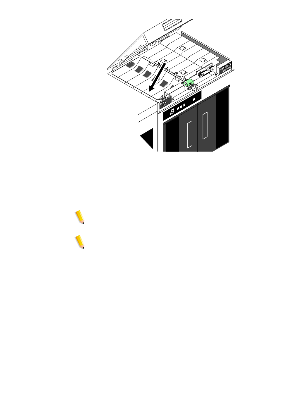
DocuTech 128/155/180 HighLight Color Operator Guide 4-17
Problem Solving
Figure 4-16 Area 17
NOTE: If your printer has frequent jams in this area, you may
need to clean the Q1106 sensor.
NOTE: High volume printer configuration only
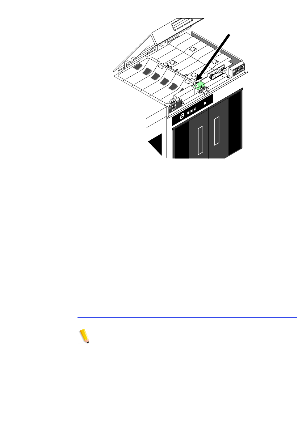
4-18 DocuTech 128/155/180 HighLight Color Operator Guide
Problem Solving
Figure 4-17 Area 18
Points to note for clearing jams in area 18:
• Sometimes the print server messages direct you to discard the
last sheet delivered to the stack following a jam in area 18.
Check for this message when clearing an area 18 paper jam.
• If your printer has frequent jams in this area, you may need to
clean the Q1107 sensor.
• If your printer has a bypass transport module, you should
check for paper jams in areas 19 and 20 after clearing an area
18 paper jam.
Clearing a paper jam in the bypass transport
NOTE: High volume printer configuration only
1. Open the bypass transport module door.
2. Press the area 19 green lever in the direction of the arrow
printed on it.
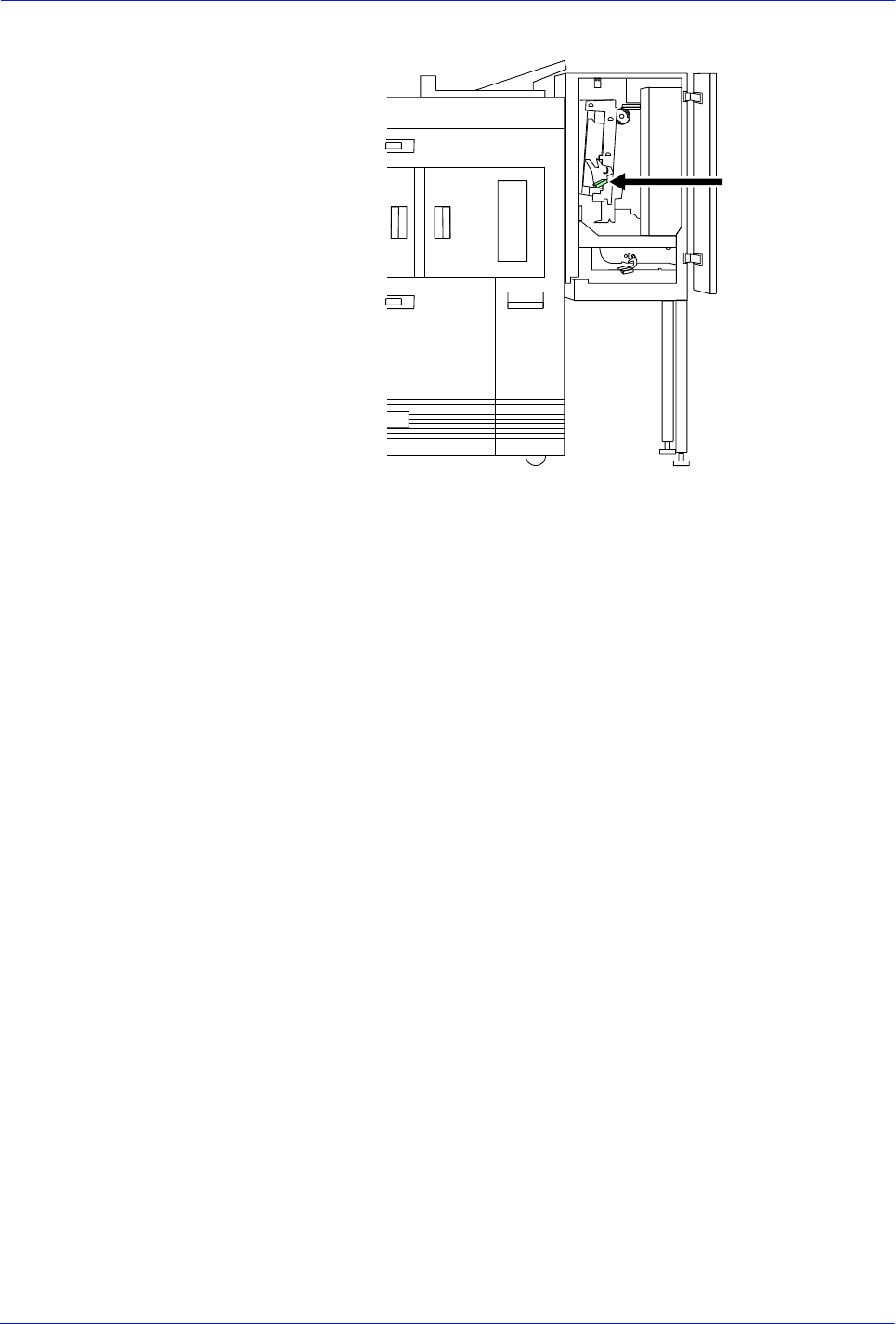
DocuTech 128/155/180 HighLight Color Operator Guide 4-19
Problem Solving
Figure 4-18 Area 19
3. Remove any paper from the exposed area.
4. Press the green lever to the left until the latch catches.
5. Press the area 20 green lever in the direction of the arrow
printed on it.
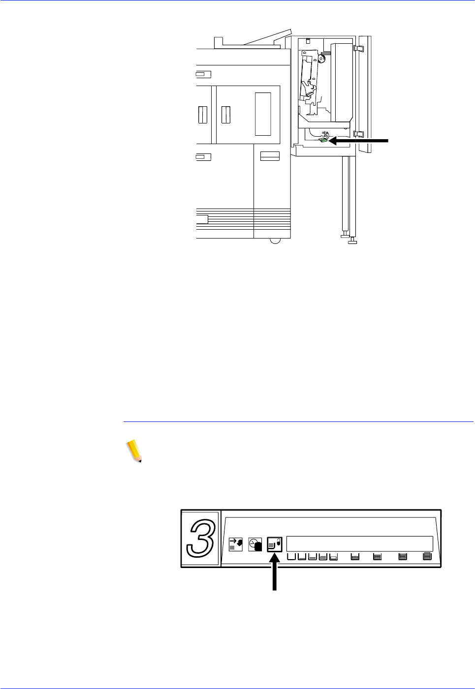
4-20 DocuTech 128/155/180 HighLight Color Operator Guide
Problem Solving
Figure 4-19 Area 20
6. Remove any paper from the exposed area.
7. Press the green lever down and to the left until the latch
catches.
8. Close the bypass transport module door.
Clearing a misfeed (feeder tray fault)
NOTE: High volume printer configuration only
1. If the Ready to Open indicator is not lit, press the Tray Unlock
button located on the feeder tray control panel.
Figure 4-20
2. When the Ready to Open indicator lights, open the feeder tray.
Pull the tray all the way out for best results.
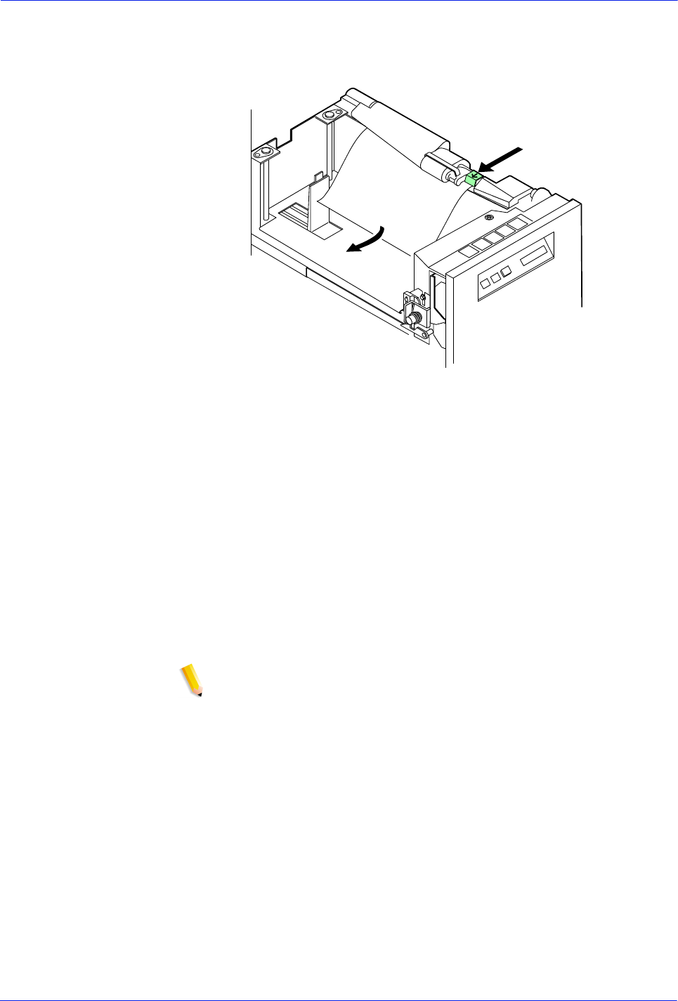
DocuTech 128/155/180 HighLight Color Operator Guide 4-21
Problem Solving
3. For the processor feeder trays, press the green lever to
unlatch the paper feeder assembly.
Figure 4-21
4. Remove and discard any partially fed paper. Ensure that:
• The paper supply is neatly stacked.
• The stack is not higher than the MAX line on the length
guide.
• The length guide is firmly touching the back edge of the
stack.
• For the high capacity feeder trays, also ensure the side
guide is firmly touching the side of the stack.
NOTE: You do not need to discard transparencies and other stiff
materials unless they are damaged.
5. For the processor feeder trays, relatch the paper feeder
assembly by pressing the green dot until the assembly clicks
into place.
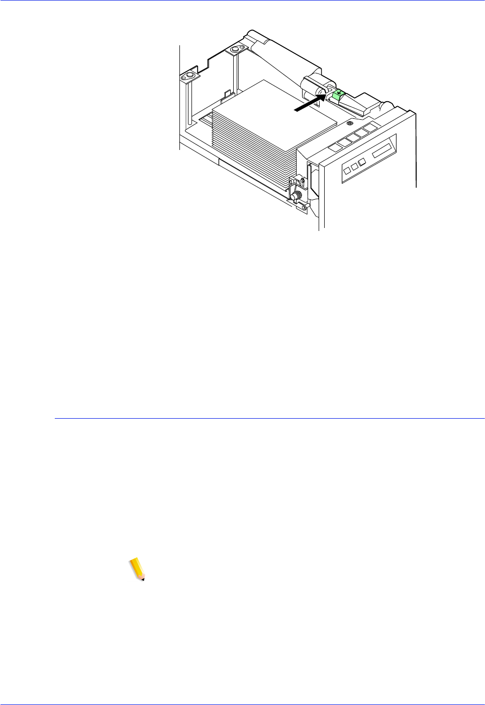
4-22 DocuTech 128/155/180 HighLight Color Operator Guide
Problem Solving
Figure 4-22
6. Slide the tray back into the printer until the tray latches and
press the Continue button to resume printing.
7. Discard any pages sent to the sample tray, purge tray, or
unused stacker bin when the misfeed was detected.
Incorrect paper size message
Perform this procedure when printing stops and a incorrect paper
size message appears on the print server.
1. Check the paper in the indicated tray. If the paper is not the
correct size for the job, either load the correct size paper or
select another feeder tray containing the correct size paper.
2. If the paper size is correct, press the Continue button to
resume printing. The message may have been caused by a
damaged sheet.
NOTE: In order to assure good print quality for your jobs, the
printer purges any dog-eared or skewed sheets. In addition, the
printer may stop and issue an incorrect paper size message.

DocuTech 128/155/180 HighLight Color Operator Guide 4-23
Problem Solving
Interposer problems
NOTE: Production publisher configuration only
Table 4-2. Resolving an interposer problem
Problem Suggested solutions
Repeated jams in
interposer
Follow the jam clearance diagram in the Printer Fault Clearance
window carefully to ensure all paper has been cleared.
Make sure the stock in trays 4 and 5 (2-Tray) or 4, 5, and 6 (3-Tray)
have been loaded correctly. Refer to the Satisfaction guides in
chapter 4, “Technical Information”, for information on loading stock
in trays 4 and 5 (2-Tray) or 4, 5, and 6 (3-Tray).
Make sure the stock loaded meets the specifications for these trays
as indicated in the Satisfaction guides in chapter 4, “Technical
Information”.
Tray 6 error
messages
Messages are displayed in the status area of the FreeFlow Print
Server. Click on any Tray 6 messages to display more information
about the message and the actions to perform. This information is
displayed in a separate Printer Fault Clearance window.
3-Tray Interposer
licensed and
enabled, error if not
installed
To determine if the 3-Tray Interposer is licensed and enabled, select
Setup > Feature Licenses on the FreeFlow Print Server to open the
License Manager window.
Look for and double-click the 3-Tray Interposer line. If the 3-Tray
Interposer is installed but not licensed, an error message appears.
Follow the steps for installing a license as documented in the
Getting Ready for the FreeFlow Print Server Installation guide.
Select Yes if the new license information should be used the printer.
Select No if the printer should use the current license information.

4-24 DocuTech 128/155/180 HighLight Color Operator Guide
Problem Solving
Finisher problems
NOTE: Production publisher configuration only
Table 4-3. Resolving a finisher problem
Problem Suggested solutions
Repeated jams in
area 14 (bindexer)
The bindexer contains three bins used by the system to sort sets.
The capacity of each bin is 125 sheets of substance 20 (75 g/m2) or
0.5 inch (13 mm) thickness.
Include inserts and covers when considering the output capacity of
the bindexer.
125 sheets of substance 20 (75 g/m2) is equal to approximately:
104 sheets of substance 24 (90 g/m2)
78 sheets of substance 32 (120 g/m2)
47 sheets of substance 110 (200 g/m2).
Check that the sets in the bindexer are less than 0.5 inch (13 mm)
thick.
If the set exceeds 0.5 inch (13 mm) thickness, reprogram the job for
fewer sheets or reduce the number of heavy-weight sheets.
When running collated, unfinished sets, the maximum sheet
capacity of the bindexer can be set between 50 and 125.
When running anything other than collated, unfinished sets, the
maximum sheet capacity of the bindexer will remain at 125.
Jammed binder
tape, such as binder
tape sticking
together, or
cosmetic defects in
the bound book
Replace the tape reel with a new reel using the procedure,
"Replacing the binder tape reel," in this guide.
Refer to the binder tape reel storage information in this guide.
Binder tape not
positioned correctly
on the top edge of
the output prints
Adjust the binder tape registration using the procedure, "Adjusting
the binder tape registration," in this guide.
Binder tape is too
long or too short on
the bottom edge of
the output prints
Adjust the binder tape length using the procedure entitled "Adjusting
the binder tape registration" in the "Routine maintenance" chapter.
If an adjustment is made to the binder tape length during a job, it will
not take effect until the next job is printed. If it is necessary to adjust
the binder tape length during a job, adjust it using the procedures in
the on-line help.
Loose binder tape
along the spine of
the completed
bound book
This is a symptom of excessive moisture in the tape. Replace the
tape reel with a new reel using the procedure, "Replacing the binder
tape reel," in the "Routine maintenance" chapter.
Refer to the binder tape storage guidelines in this guide.

DocuTech 128/155/180 HighLight Color Operator Guide 4-25
Problem Solving
Binder tape fault
NOTE: Production publisher configuration only
To clear a binder tape fault:
1. Open the finisher doors.
Repeated tape
feeding problems,
such as binder tape
not unwinding from
the reel
If the binder tape is sticking together, or if there are cosmetic defects
in the bound book, replace the tape reel with a new reel using the
procedure, "Replacing the binder tape reel," in the "Routine
maintenance" chapter.
Refer to the binder tape storage information in this guide.
Refer to the binder cleaning information in this guide.
Refer to information on calling the Customer Support Center in this
guide.
Stitcher fault codes
displayed in the fault
frame
Fault Code P12-218
Fault Code P12-219
Select the [Finishing] button on the Printer Manager window.
Deselect [Stitcher] on the Finishing window and refer to the
procedure, "Calling for assistance," in this guide.
Stitcher A problems. Perform the procedure, "Clearing a stitcher
spool A fault," in this guide.
Stitcher B problems. Refer to information on calling the Customer
Support Center in this guide.
Poor stitch quality or
short stitches
Reliable stitching can be expected with up to 65 sheets of substance
20 (75 g/m2) or 0.28 inch (7 mm) thick sets. Less reliable stitching
can be expected with over 70 sheets of substance 20 (75 g/m2).
Running intermixed stock heavier than substance 20 (75 g/m2) will
reduce the capacity of the stitcher.
To avoid short clinches, use the stitch override only when using a
lightweight paper. Stitch override allows the system to run beyond
the stitching limit. The system will shut down at 125 sheets.
Reduce the stock weight to enable the stitching of more sheets per
set.
Refer to the satisfaction guides in the "Technical information"
chapter.
Sheets are spilling
out of the top tray
The capacity of the top tray is 500 sheets of substance 20 (75 g/m2)
or 2 inches (51 mm) in height. When intermixed stock or paper
heavier than substance 20 (75 g/m2) is being run, the capacity of
the top tray is reduced.
500 sheets of substance 20 (75 g/m2) is equal to approximately:
415 sheets of substance 24 (90 g/m2)
310 sheets of substance 32 (120 g/m2)
225 sheets of substance 110 (200 g/m2)
If using any paper heavier than substance 20 (75 g/m2) or
intermixed stock of different weights, unload the top tray before the
count in the tray reaches its capacity limit.
Refer to the satisfaction guides in the "Technical information"
chapter.
Table 4-3. Resolving a finisher problem

4-26 DocuTech 128/155/180 HighLight Color Operator Guide
Problem Solving
2. Open the top cover.
WARNING: The binder tape adhesive is hot, approximately 425°F
(218°C). Allow the binder to cool for 5 minutes with the finisher
doors and top cover open before touching the binder tape.
3. Follow the instructions on the screen to determine the area (17
or 18) that should be cleared.
4. If area 17 is displayed and the binder tape is present, stop and
follow the WARNING. Remove the binder tape and paper.
Proceed to step 6.
5. If area 17 is displayed and the binder tape is not present,
follow the instructions on the area 17 label and remove all
paper.
6. Ensure that area 17 is clear of all binder tape adhesive. If the
area is not clear, clean the binder using the procedure,
"Cleaning the binder," in this guide.
WARNING: The binder tape adhesive is hot, approximately 425°F
(218°C). Allow the binder to cool for 5 minutes with the finisher
doors and top cover open before touching the binder tape.
7. If area 18 is not displayed, proceed to step 10.
8. If area 18 is displayed and the entire binder tape length is not
aligned with the tape feeder assembly, stop and follow the
WARNING. Proceed to step 10.
9. If area 18 is displayed and the entire binder tape length is
aligned with the tape feeder assembly, proceed to step 10.
10. Remove the binder tape.
11. Ensure that area 18 is clear of all binder tape adhesive. If it is
not, clean the binder using the procedure, "Cleaning the
binder," in the "Routine maintenance" chapter.
12. Close the finisher doors.
13. Close the top cover.
Stitcher spool A fault
NOTE: Production publisher configuration only
Repeated jams in area 17 may be caused by the following
problems:
• Stitcher wire not feeding properly
• A kink in the stitcher wire
1. Open the finisher doors.
2. Lift the stitcher panel, which is located directly above the
stitcher spools.
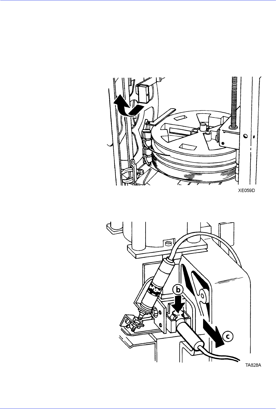
DocuTech 128/155/180 HighLight Color Operator Guide 4-27
Problem Solving
NOTE: If the spool is empty, replace the stitcher spool A. Refer to
online help for details.
3. Ensure that there is wire on the spool.
4. Pull the green stitcher head release handle forward and up
until it latches into place, as shown in figure 4-23.
Figure 4-23 Stitcher head release handle
Figure 4-24 Removing the stitcher wire plug
5. Remove the stitcher wire plug.
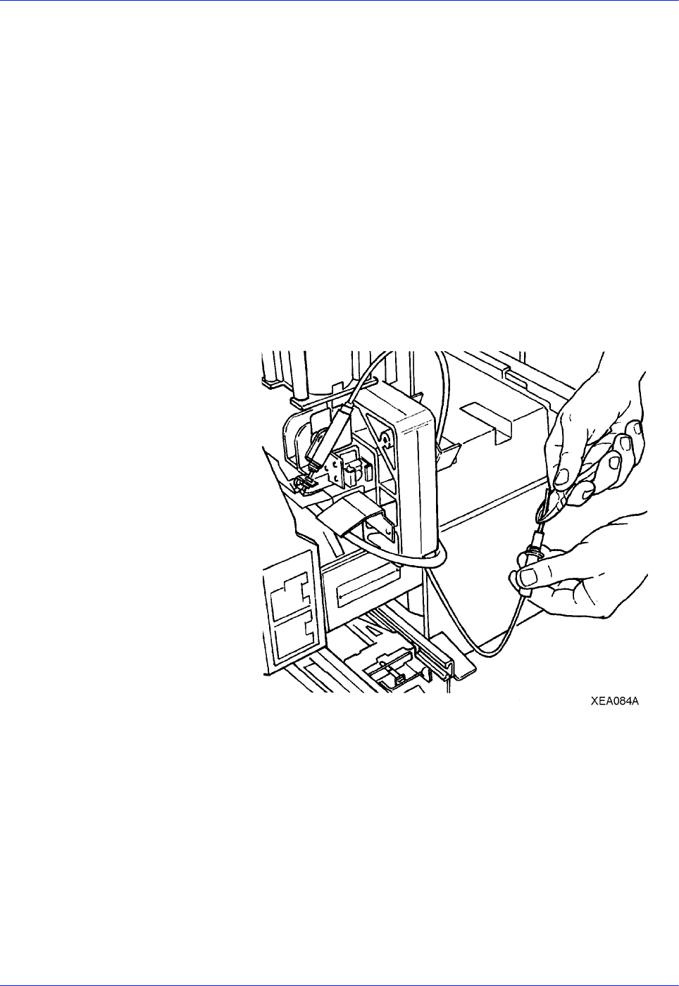
4-28 DocuTech 128/155/180 HighLight Color Operator Guide
Problem Solving
• The stitcher wire plug is located above the binder area, as
shown in figure 4-24.
• Press and hold down the release clip.
• Pull the plug out of the stitcher head.
6. Remove any damaged wire.
• Using the wire cutters, slowly and carefully pull
approximately 3 feet (1 meter) of wire out of the stitcher
plug.
• The wire cutter tool needed to perform this procedure is
located next to stitcher spool B, as shown in the lower left
corner of figure 4-23.
• Cut the wire carefully, leaving approximately 2 inches (50
mm) of wire extending from the stitcher plug, as shown in
figure 4-25.
Figure 4-25 Cutting the wire
7. Insert the plug into the measuring bracket, as shown in figure
4-26.
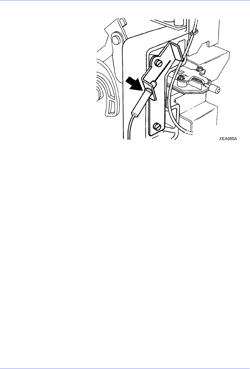
DocuTech 128/155/180 HighLight Color Operator Guide 4-29
Problem Solving
Figure 4-26 The measuring bracket
8. Feed the wire until the wire touches the back of the measuring
bracket.
9. Remove any stitcher wire fragments.
• Fold a piece of copy paper in half lengthwise. Place the
folded sheet of copy paper under the stitcher head, as
shown in figure 4-27.
• Pull out the stitcher knob and allow it to snap back into
place to free any stitcher wire fragments.
• Remove the copy paper carefully, being sure not to drop
any wire fragments into the system.
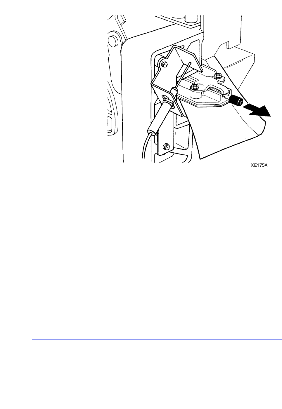
4-30 DocuTech 128/155/180 HighLight Color Operator Guide
Problem Solving
Figure 4-27 Removing the wire fragments
10. Push the green stitcher head release handle down and back.
11. Pull the plug from the measuring bracket.
12. Insert the plug into the stitcher head until the plug snaps into
place.
NOTE: Ensure that the wire cutters are not touching the stitcher
spools. This can prevent the stitcher wire from feeding properly.
13. Place the wire cutters in the storage bracket.
NOTE: Ensure that the stitcher panel has been lowered. The
stacker will not deliver printed sets if the stitcher panel is left in the
up position
14. Lower the stitcher panel.
15. Close the finisher doors. The printer icon indicates "Ready."
Checking paper curl
You can adjust the decurler lever to correct most paper curl
problems. Refer to the paper curl chart, later in this chapter, to
determine the amount of curl in the paper stock.
Perform the following to measure paper curl:
1. Print five one sided (simplex) 8.5 by 11 inch or A4 sheets.

DocuTech 128/155/180 HighLight Color Operator Guide 4-31
Problem Solving
2. Hold the printed sheets by the top center of the short edge,
keeping the image toward you.
Figure 4-28 Paper curl chart
3. Place the bottom edge of the prints over the paper curl
measurement chart on the line that best represents the curve
of the sheets.
• If the curl on the printed paper stock measures between +2
and -2, do not change the decurler setting.
• If the curl is between +2 and +3, or -3 and -4, adjust the
decurler lever.
Customer Support Center
Before calling the Customer Service Support Center for service,
ensure you have read this information and have tried the
corrective actions described here. If the problem persists, gather
the necessary information (details follow) and call the appropriate
Customer Service Support Center phone number. Your site
representative can supply you with the telephone number for the
Customer Service Support Center in your area.
The correct phone number is attached to your printer at installation
time.
Before calling for service, make note of:
• Print, job fault messages, or status messages that appear on
the print server
• Indicator lights that may or may not be lit
• Status codes that appear in the message display of the tape
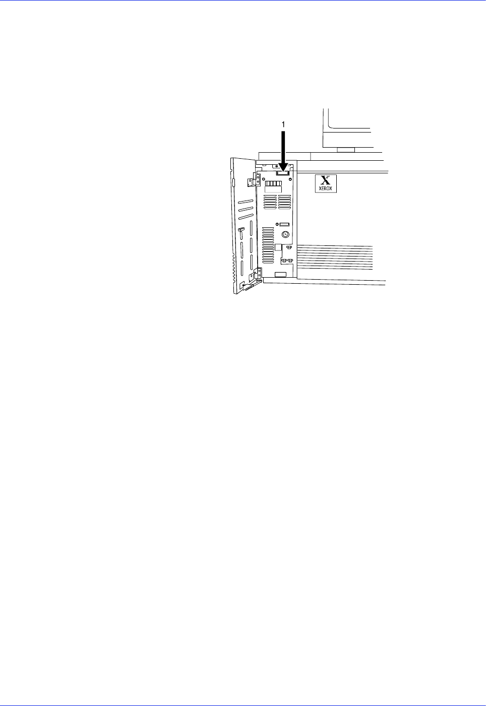
4-32 DocuTech 128/155/180 HighLight Color Operator Guide
Problem Solving
drive control panel if there is a tape drive problem
Your call is answered by a representative who asks you for your
equipment model. You are also asked for:
• Your printing system serial number, which is located on a
panel inside the printer, behind the small door on the left.
Figure 4-29 Location of printing system serial number
• Your name
• Your company name
• The system condition or status
This information is given to a customer service representative who
calls you back to discuss the information and gives you an
estimated time of arrival or to assist you over the phone to resolve
the problem.

DocuTech 128/155/180 HighLight Color Operator Guide 5-1
5 Technical information
This section contains the hardware and software capacity
guidelines for the DocuTech HLC systems. It includes the printer
specifications, the satisfaction guides for paper trays and stock,
and Tips on storing paper and improving printing reliability. For
complete system specifications, refer to the appropriate
Installation Planning Guide.
DocuTech printer specifications
This section contains information on expected print rates for the
DocuTech printers, as well as information on the weight, sizes,
and capacities for their paper trays.
Printer rates
Print rate
(per minute)
DT HLC 180: 180 prints per minute - 8.5 x 11 inch (216 x 279
mm), 8.5 x 14 inch (216 x 254 mm), and A4 stock; 77 prints - 17 x
11 inch (432 x 279 mm) or A3 stock
DT HLC 155: 155 prints per minute - 8.5 x 11 inch (216 x 279
mm), 8.5 x 14 inch (216 x 254 mm), and A4 stock; fewer prints -
17 x 11 inch (432 x 279 mm) or A3 stock
DT HLC 128: 128 prints per minute - 8.5 x 11 inch (216 x 279
mm), 8.5 x 14 inch (216 x 254 mm), and A4 stock; fewer prints -
17 x 11 inch (432 x 279 mm) or A3 stock
128, 155, or 180 prints - custom stock - depending upon the size
specified for the stock
Performance can be less than optimal for the some unique stock
sizes. For example, for stock having a process direction
dimension that is equal to or greater than 8.6 inches (218 mm)
and less than or equal to 9 inches (229 mm) the performance at
best will be 175 pages per minute.

5-2 DocuTech 128/155/180 HighLight Color Operator Guide
Technical information
Paper tray capacities
Stock weight
(all trays)
Substance 16 to 110 (60 to 200 g/m2)
Tray 1
Stock sizes
US letter (8 1/2 x 11 inches)
US legal (8 1/2 X 14 inches)
9 x 11 inches
A4
8 1/2 x 13 inches
223 x 297 mm
Custom (Width = 8 to 9 inches (203 to 229 mm), Length = 10 to 14
inches (254 to 356 mm))
Capacity 1100 sheets, substance 20 (75 g/m2)
Tray 2
Stock sizes
US letter (8 1/2 x 11 inches)
US legal (8 1/2 x 14 inches)
9 x 11 inches
A4
8 1/2 x 13 inches
223 x 297 mm
Custom (Width = 8 to 9 inches (203 to 229 mm), Length = 10 to 14
inches (254 to 356 mm))
Capacity 600 sheets, substance 20 (75 g/m2)
Tray 3 US Letter (8 1/2 x 11 inches)
Stock Sizes US Legal (8 1/2 x 14 inches)
US Ledger (17 x 11 inches)
9 x 11 inches
A3
A4
8 1/2 x 13 inches
223 x 297 mm
ISO B4
JIS B4
Custom (Width = 8 to 17 inches (203 to 432 mm), Length = 10 to
14.33 inches (254 to 364 mm))
Capacity 2600 sheets, substance 20 (75 g/m2)
NOTE: This tray information is applicable to trays 3-6 on the High
volume printer configuration and tray 3 on the Production
publisher configuration.

DocuTech 128/155/180 HighLight Color Operator Guide 5-3
Technical information
Tray 4
Stock Sizes
US Letter (8 1/2 x 11 inches)
US Legal (8 1/2 x 14 inches)
US Ledger (17 x 11 inches)
9 x 11 inches
A3
A4
8 1/2 x 13 inches
223 x 297 mm
ISO B4
JIS B4
Custom (Width = 8 to 17 inches (203 to 432 mm), Length = 10 to
14.33 inches (254 to 364 mm))
Capacity 550 sheets, substance 20 (75 g/m2), post-process only
NOTE: This tray information applies to the Production publisher
configuration.
Tray 5
Stock Sizes
US Letter (8 1/2 x 11 inches)
US Legal (8 1/2 x 14 inches)
US Ledger (17 x 11 inches)
9 x 11 inches
A3
A4
8 1/2 x 13 inches
223 x 297 mm
ISO B4
JIS B4
Custom (Width = 8 to 17 inches (203 to 432 mm), Length = 10 to
14.33 inches (254 to 364 mm))
Capacity 2600 sheets, substance 20 (75 g/m2), pre or post-process
NOTE: This tray information applies to the Production publisher
configuration.
Tray 5 and 6
Stock Sizes (3-Tray
Interposer)
US Letter (8 1/2 x 11 inches)
US Legal (8 1/2 x 14 inches)
US Ledger (17 x 11 inches)
9 x 11 inches
A3
A4
8 1/2 x 13 inches

5-4 DocuTech 128/155/180 HighLight Color Operator Guide
Technical information
223 x 297 mm
ISO B4
JIS B4
Custom (Width = 8 to 17 inches (203 to 432 mm), Length = 10 to
14.33 inches (254 to 364 mm))
Capacity 500 sheets in each tray, substance 20 (75 g/m2), pre or post-
process
This tray information applies to the Production publisher
configuration.
Additional paper capacities
Inverter
Stock sizes
(or duplex tray)
8 x 10 inches to 17 x 11 inches (203 x 254 mm to 432 x 279 mm)
Top tray
Stock sizes
8x10 inches to 17 x 11 inches (203 x 254 mm to 432 x 279 mm)
Capacity 500 sheets, substance 20 (75 g/m2)
Stacker
Stock sizes
8 x 10 inches to 9 x 14 inches (203 x 254 mm to 229 x 356 mm)
Capacity 3000 sheets (1500 inboard and 1500 outboard), substance 20 (75
g/m2)
Stitcher Stock
sizes
8 x 10 inches to 9 x 14 inches (203 x 254 mm to 229 x 356 mm)
Capacity 2 to 70 sheets, substance 20 (75 g/m2)
Stitches per spool Approximately 35,000
Binder Stock sizes 8.5 x 11 inches (216 x 279 mm)
Capacity 15 sheets (7 sheets with index covers) to 125 sheets of substance
20 (75 g/m2) or equivalent thickness
Binds per spool Approximately 425

DocuTech 128/155/180 HighLight Color Operator Guide 5-5
Technical information
Printer satisfaction guides
Use the following information to ensure your satisfaction with the
feeding of the print material.
Stock storage
Although the system was designed to handle a wide range of
stock, many factors can affect performance and print quality.
One of the factors that can affect system performance is paper
curl. Humidity and moisture cause the natural paper curl to
increase. Too much curl causes jams in the system.
The following practices minimize paper curl during storage of the
paper stock.
• Keep the paper wrapped as long as possible. Do not unwrap
the paper until it is needed.
• Store the reams of paper in their carton.
• Do not leave the carton directly on the floor. Place something
beneath the carton, such as a wooden pallet.
Improving the feeding reliability
The following practices improve the feeding reliability of the
system.
• Plan the jobs to minimize the amount of paper left in the
system during the night.
• Load the paper quantity based on the number of prints
required.
• When paper is taken from a storage area with a different
humidity or temperature, keep it in the room where it will be
used for at least 48 hours before loading the paper into the
system.
• To make adjustments to the DocuTech 128/155/180 HLC for
the curl in the paper, refer to the “Routine maintenance” and
“Problem solving” sections of this guide.

5-6 DocuTech 128/155/180 HighLight Color Operator Guide
Technical information
Stock satisfaction guides
Table 5-1. Satisfaction guide for paper trays 1 and 2
Table 5-2. Satisfaction guide for paper tray 4 Interposer ONLY
NOTE: Production publisher configuration only
Stock Reliable feeds may
be expected
Less reliable feeds may be
expected Suggested alternatives
Size 8 x 10 inches to 9 x 14
inches (203 x 254 mm
to 229 x 356 mm)
Stock smaller than 8 x 10 inches
cannot be used.
For stock larger than 9 x 14
inches (229 x 356 mm), refer to
the tray 3 satisfaction guide.
Weight Substance 20 to 110
(75 to 200 g/m2)
Substance 16 to 19 (60 to 72 g/
m2)
Weights outside the limits shown
are not recommended.
Substance 110 (200 g/m2) must
be long grain. Do not use short
grain.
Capacity Tray 1 - 1100 sheets,
substance 20 (75 g/
m2)
Tray 2 - 600 sheets.
substance 20 (75 g/
m2)
For greater capacity, use tray 3.
Type or
condition
Xerographic bond
paper in good
condition Drilled
stock, fanned
thoroughly Tab stock
in perfectly flat
condition
Slightly curled paper intermixed
weight Transparencies Label
stock Adhesive drafting film
Paper with reinforced edges
Do no use excessively curled
paper.
Substance 110 (200 g/m2) must
be long grain Do not use short
grain.
Use transparencies with a white
stripe. Freshly printed offset
prints, use tray 3.
Refer to the “Using various
stocks” section for any stock not
defined in this guide.
Stock Reliable feeds may
be expected
Less reliable feeds may be
expected Suggested alternatives
Size 8 x 10 inches to 17 x
11 inches (203 x 254
mm to 432 x 279 mm)
Smaller or larger sizes cannot be
used.

DocuTech 128/155/180 HighLight Color Operator Guide 5-7
Technical information
Table 5-3. Satisfaction guide for paper trays 3, 4, 5, and 6
NOTE: High volume printer configuration only
Weight Substance 16 to 110
(60 to 200 g/m2)
Weights outside the limits shown
are not recommended.
Substance 110 (200 g/m2) must
be long grain except 17 x 11 inch
(432 x 279 mm) substance 110
(200 g/m2) which must be short
grain.
Capacity 550 sheets, substance
20 (75 g/m2)
Type or
condition
Xerographic bond
paper in good
condition
Drilled stock, fanned
thoroughly
Slightly curled paper
Intermixed weights
Xerox vellum
Full cut tabs
Label stock
Adhesive drafting film
Paper with reinforced edges
Do not use excessively curled
paper
Substance 110 (200 g/m2) must
be long grain. Do not use short
grain.
Refer to the “Using various
stocks” section for any stock not
defined in this guide.
Stock Reliable feeds may
be expected
Less reliable feeds may be
expected Suggested alternatives
Stock Reliable feeds may
be expected
Less reliable feeds may be
expected Suggested alternatives
Size 8 x 10 inches to 17 x
11 inches (203 x 254
mm to 432 x 279 mm)
Smaller or larger sizes cannot be
used.
Weight Substance 16 to 110
(60 to 200 g/m2)
Weights outside the limits shown
are not recommended.
Substance 110 (200 g/m2) must
be long grain except 17 x 11 inch
(432 x 279 mm) substance 110
(200 g/m2) which must be short
grain.
Capacity 2600 sheets,
substance 20 (75 g/
m2)

5-8 DocuTech 128/155/180 HighLight Color Operator Guide
Technical information
Table 5-4. Satisfaction guide for 2-sided printing
Using various stocks
The following table lists stock that have been evaluated and tested
for use in this system. There are many other stocks available,
some of which may not provide the same degree of user
satisfaction. Refer to the “Using non-standard stock” section in this
guide
Type or
condition
Xerographic bond
paper in good
condition
Drilled stock, fanned
thoroughly
Slightly curled paper
Intermixed weights
Xerox vellum
Full cut tabs
Label stock
Adhesive drafting film
Paper with reinforced edges
Do not use excessively curled
paper
Substance 110 (200 g/m2) must
be long grain. Do not use short
grain.
Precut tabs - use tray 1 or 2.
Transparencies with a white
stripe, use tray 1 or 2.
Freshly printed offset prints, use
tray 3.
Refer to the “Using various
stocks” section for any stock not
defined in this guide.
Stock Reliable feeds may
be expected
Less reliable feeds may be
expected Suggested alternatives
Stock Reliable feeds may
be expected
Less reliable feeds may be
expected Suggested alternatives
Size 8 x 10 inches to 17 x
11 inches (203 x 254
mm to 432 x 279 mm)
17 x 11 inch (432 x 279 mm)
paper can only be sent to the top
tray.
Weight Substance 16 to 110
(60 to 200 g/m2)
Substance 110 (200 g/
m2) must be long
grain.
Weights outside the limits shown
are not recommended.
Type or
condition
Xerographic bond
paper in good
condition
Drilled stock, fanned
thoroughly
Slightly curled paper
Paper with reinforced edges
Do not use excessively curled
paper.
Refer to the “Using various
stocks” section for any stock not
defined in this guide.

DocuTech 128/155/180 HighLight Color Operator Guide 5-9
Technical information
Table 5-5. Satisfaction guide for various stocks
Stock Type Instructions for use
Substance 13
(49 g/m2) paper
Use trays 3, 4, 5, or 6.
Do not run 2-sided prints.
Load the paper with seam side down into tray
3.
Optimum satisfaction can be expected with
8.5 x 11 inch (216 x 279 mm) or larger paper.
Substance 16 (60 g/
m2) paper
Load paper with seam side up into trays 1
and 2; seam side down into tray 3, 4, 5, or 6.
Optimum satisfaction can be expected from
tray 3, 4, 5, or 6.
Substance 20 (75 g/
m2) paper
Load the paper with seam side up into trays 1
and 2; seam side down into trays 3, 4, 5, and
6.
Card stock
Xerox substance 65
(176 g/m2)
Substance 110 (200 g/
m2) long grain (index)
Card stock can be run from any tray.
Reduce set size if frequent paper jams or
bindexer jams occur. If collated unfinished,
another solution is to lower the value of the
bindexer capacity set in the SWITCHES
mode.
Xerox 4024, substance
20
(75 g/m2)
3 hole drilled
4 hole drilled
7 hole drilled
Load the paper into trays 1 and 2 with holes
to the right; load the paper into trays 3, 4, 5,
and 6 with holes to the left.
Use the Image Shift or Reduce/Enlarge
options to avoid printing near the holes.
Fan the paper and check the paper for loose
paper plugs before loading the paper into the
trays.
Never-tear, 3 hole
drilled
Load the paper into trays 1 and 2 with holes
to the right; load the paper into trays 3, 4, 5,
and 6 with holes to the left.
Do not bind or run 2-sided prints.
Never-tear Do not bind or run 2-sided prints.

5-10 DocuTech 128/155/180 HighLight Color Operator Guide
Technical information
3 hole drilled, edge
reinforced, 4024 DP
paper
Do not stitch or bind. Do not run with tabs.
Tabs can be inserted off-line.
For optimum satisfaction, use the paper trays
1 and 2 plate assembly. The plate assembly
can be ordered by a Customer Service
Representative. Up to 500 sheets can be
placed in the tray.
Load the paper into all trays with holes to the
left, reinforced side down.
Select <Properties...> on the Trays pull-
down menu. On the Stock window, under
Type, select <Drilled>.
Image quality problems may occur near the
reinforcement with side 2 printing.
Remove the paper immediately before use to
ensure that prints stay flat.
Print with no more than 200 sheets in a tray.
Select a quantity of 50 or fewer at a time.
Transparencies with a
0.5 inch (13 mm) white
stripe
Load the stock with the white stripe to the
right into trays 1 and 2.
Load the shiny side up for optimum
performance.
Removable stripe
transparencies
Do not load more than 50 removable-stripe
transparencies into trays 1 and 2.
With the white stripe to the right, place the
transparencies on top of approximately 50
sheets of paper in the tray.
Do not run as inserts to a bound job. Printing
is not allowed on inserts.
Tabs Mylar tabs should be run out of tray 4.
Preprinted stock Preprinted forms must be made up of ink that
has the following characteristics:
Can withstand temperatures up to 400°F
(204°C)
Can withstand pressure of 140 psi at the
above temperature
Can withstand the above conditions for 25
milliseconds
High speed
transparencies with
white stripe
Load the stock with the stripe to the right in
trays 1 and 2.
Label stock Load the stock face up into trays 1 and 2;
face down into trays 3, 4, 5, and 6.
Do not select 2-sided prints.
Letterhead (preprinted) Load the paper into trays 3, 4, 5, and 6; side
1 with the printed side down, top edge to the
front of the tray.
Load the paper into trays 1 and 2; side 1 up
with the top edge to the front of the tray.
Do not use freshly preprinted paper in trays 1
and 2.
Stock Type Instructions for use

DocuTech 128/155/180 HighLight Color Operator Guide 5-11
Technical information
Do not use the following stocks:
• Multipart forms
• Stocks outside of the recommended size and weight ranges
Using non-standard stock
Using stock of non-standard width or length in the printer may
have a negative impact on system performance. Refer to the
following table for a listing of sizes and possible resulting impacts.
Table 5-6. Stock width impact on system performance
Textured paper Heavily textured paper may produce prints
with a ragged character appearance or
deletions. To test, run a proof print.
Window stock Run if the window is 2.2 to 4 inches (57 to
102 mm) from the top edge of the paper and
at least 1 inch (25.4 mm) from each side of
the paper.
Run only as the first page or a front cover to
avoid finisher bin jams.
Load the window stock face-up into a tray
(tray 1 or 2 is recommended) with the top
edge toward the front of the tray.
If running plastic-covered window stock,
there may be some distortion. To test, run a
proof copy.
Xerox Carbonless Xerox Carbonless Paper is recommended.
Stock Type Instructions for use
Stock width Impact on performance
8.67 to 9 inches (221
to 229 mm) in trays 1,
2, 3, 4, 5, and 6.
Extended runs may increase the risk of
temporary background.
Increased risk of lead-edge image deletions on
each successive sheet.
Stock programming errors may go undetected
because stock width checking is not performed.
9 inches (229 mm) to
less than 14.2 inches
(361 mm) in trays 3,
4, 5, and 6.
Image offset may occur following a printer
malfunction; for example, fuser jams.
Running stock wider than 9 inches (229 mm)
(other than 17 x 11 inches or A3) may increase
the risk of misregistration, skew, and tray 3
elevator problems.

5-12 DocuTech 128/155/180 HighLight Color Operator Guide
Technical information
Table 5-7. Stock length impact on system performance
Paper stock rotation
This section identifies the limitations on the rotation of paper stock
in the DocuTech 128/155/180 HLC Bypass Transport when using
a third-party finishing device.
Background
Due to the physical limitations of the DocuTech 128/155/180 HLC
Bypass Transport, some paper stocks will be damaged or will jam
while being rotated. Currently, when using an external finishing
Stock length Impact on performance
Over 11 inches (279
mm) to less than
11.7 inches (297
mm)
Over 11.7 inches
(279 mm) to less
than 13 inches (330
mm)
Over 13 inches (330
mm) to less than 14
inches
(356 mm)
Over 14 inches (356
mm)
The transfer assist mechanism is preset to
optimize image transfer for the exact stock
lengths of 11 inches (279 mm), 11.7 inches (297
mm), 13 inches (330 mm), and 14 inches (356
mm). Stock lengths falling between these exact
lengths present an increased risk for bottom-
edge deletions.
14.33 inches (B4
JIS)
Background, smudging, or white spaces may
occur when printing between the 14 inch area
and the edge of the paper.
10 inches (254 mm)
to less than 11
inches (279 mm)
Because the 11 inch transfer mechanism is
used for all stock lengths less than 11 inches
(279 mm), there is an increased risk of
contaminating the back side of sheets after
switching back to longer stock.
11.2 inches (284
mm) to less than
11.5 inches
(292 mm)
11.9 inches (302
mm) to less than
12.2 inches (310
mm)
13.5 inches (343
mm) to less than
13.7 inches (348
mm)
Unresolved stock size mismatch conflict
messages may occur for stock lengths in these
ranges. Job and stock programming work-
arounds may be required.

DocuTech 128/155/180 HighLight Color Operator Guide 5-13
Technical information
device that is not a Signature Booklet Maker, there is no message
displayed on the FreeFlow Print Server to warn the Operator that
the paper stock to be rotated will not fit in the Bypass Transport.
The Signature Booklet Maker attached to a DocuTech 128/155/
180 HLC printer is only capable of handling paper stock up to 9
inches (229 mm) in length in a portrait orientation.
With the introduction of other DFA-complaint finishing devices for
use with the DocuTech 128/155/180 HLC family of printers,
additional paper stock sizes can be handled by the finishing
devices, both straight from the Bypass Transport or rotated.
Limitations
Do not rotate paper sizes that will not fit through the DocuTech
128/155/180 HLC Bypass Transport to a third party finishing
device.
Before creating a document to be rotated by the Bypass
Transport, set the paper stock size required to fit within the
limitations detailed in the following tables and as follows:
• The diagonal dimension of the paper stock must be equal to or
less than 18 inches (457 mm).
• The paper stock must be within the paper stock size
parameters of the DocuTech 128/155/180 HLC printer paper
trays.
Refer to the FreeFlow Print Server on-line help system for
information on setting finisher devices and finisher profiles to
enable rotation to a third party finisher.
Table 5-8. Common US paper sizes
Common
size name
Inches x
inches
Millimeter
equivalent Diagonal in inches Can be
rotated
Comment
(similar to or the
same as)
8.0 x 10.75 203 x 273 13.40 YES
US Letter/ US
A-size
8.5 x 11.0 216 x 279 13.90 YES 2-up of US 5.5 x
8.5 in.
(statement)
9.0 x 12.0 229 x 305 15.00 YES 2-up of US 6.0 x
9.0 in. (common
“book” size)
US Legal 8.5 x 14.0 216 x 356 16.38 YES ISO Foolscap
9.0 x 14.0 229 x 356 16.64 YES 2-up of US 7.0 x
9.0 in.
9.0 x 15.0 229 x 381 17.49 NO* 2-up of US 7.5 x
9.0 in.

5-14 DocuTech 128/155/180 HighLight Color Operator Guide
Technical information
*Although the diagonal meets the 18-inch (457 mm) rotation limit,
the paper stock long dimension exceeds the processor path width.
The sheet must stay in the short-edge feed orientation throughout
the paper path.
Table 5-9. Common sizes used in Europe, Japan, Canada, etc.
10.5 x 14.5 267 x 368 17.90 NO* 2-up of US 7.25 X
10.5 in.
(Executive)
US Ledger/
US B-Size
11.0 x 17.0 279 x 432 20.25 NO 2-up of US 8.5 x
11.0 in. (Letter)
Common
size name
Inches x
inches
Millimeter
equivalent Diagonal in inches Can be
rotated
Comment
(similar to or the
same as)
Common
size name
Inches x
inches
Millimeter
equivalent Diagonal in inches Can be
rotated
Comment
(similar to or the
same as)
8.0 x 10.75 203 x 273 13.40 YES
US Letter/ US
A-size
8.5 x 11.0 216 x 279 13.90 YES 2-up of US 5.5 x
8.5 in.
(statement)
9.0 x 12.0 229 x 305 15.00 YES 2-up of US 6.0 x
9.0 in. (common
“book” size)
US Legal 8.5 x 14.0 216 x 356 16.38 YES ISO Foolscap
9.0 x 14.0 229 x 356 16.64 YES 2-up of US 7.0 x
9.0 in.
9.0 x 15.0 229 x 381 17.49 NO* 2-up of US 7.5 x
9.0 in.
10.5 x 14.5 267 x 368 17.90 NO* 2-up of US 7.25 X
10.5 in.
(Executive)
US Ledger/
US B-Size
11.0 x 17.0 279 x 432 20.25 NO 2-up of US 8.5 x
11.0 in. (Letter)
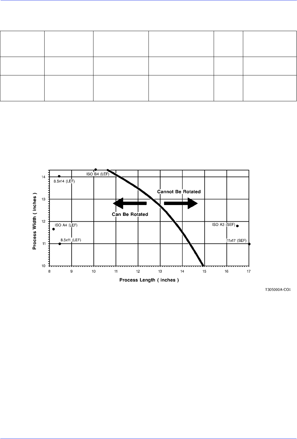
DocuTech 128/155/180 HighLight Color Operator Guide 5-15
Technical information
Table 5-10. Other paper sizes that can be rotated
For media sizes that are not listed in the above tables, view the
graph shown in figure 5-1. The graph can be used to determine
which sizes of media can and cannot be rotated within the Bypass
Transport.
Figure 5-1. Rotatable and non-rotatable sizes (“as loaded”
media size)
Sizes whose dimensions are located on the left of the curve or on
the line itself have a diagonal that is less than or equal to 18.0
inches (457 mm) and therefore can be rotated. Those sizes whose
dimensions are located to the right of the curve have diagonals
greater than 18.0 inches (457 mm) and therefore cannot be
rotated. Some common ISO sizes and US sizes are shown on the
graph as examples.
Common
size name
Inches x
inches
Millimeter
equivalent Diagonal in inches Can be
rotated
Comment
(similar to or the
same as)
Largest
square
12.73 x 12.73 323 x 323 18.00 YES
Largest
rectangle
10.89 x 14.33 277 x 364 18.00 YES Length is
constrained by
paper path width.

5-16 DocuTech 128/155/180 HighLight Color Operator Guide
Technical information
Finisher satisfaction guides
NOTE: Production publisher configuration only
The following guides summarize the stacker, stitcher, binder, and
top tray capabilities.
Table 5-11. Stacker capacity
Stock
Reliable stacking may be
expected
Less reliable stacking may be
expected Suggested alternatives
Size 8 x 10 inches to 9 x 14
inches (203 x 254 mm to
229 x 356 mm)
Use the top tray for larger
sizes
Weight Substance 16 to 20 (60 to
75 g/m2)
Weights outside the limits
shown are not recommended.
Set or stack
size
Substance 16 to 20 (60 to
75 g/m2)
Over substance 20 (75 g/
m2) stock as sets or stacks
increases the likelihood of
bindexer jams.
When using copy paper
heavier than substance 20 (75
g/m2), limit the stack or set
size by dividing the set into
parts. Combine prints when
completed and finish offline, if
required. For collated
unfinished sets, the maximum
sheet capacity of the bindexer
can be set to between 50 and
125.
Stacker
capacity
Unfinished sheets:
3300 sheets, substance
16 (60 g/m2)
3000 sheets, substance
20 (75 g/m2)
2500 sheets, substance
24 (90 g/m2)
1875 sheets, substance
32 (120 g/m2)
1360 sheets, substance
110 (200 g/m2)
To allow a continuous run,
unload outer stack before
inner stack reaches capacity.
Type or
condition
Xerographic bond paper in
good condition
Drilled paper
Slightly curled paper Do not use excessively curled
paper.
Transparencies must contain
some opaque sheets to avoid
finisher jams.
Stock not defined here is
included in the “Using various
stocks” section in this guide.

DocuTech 128/155/180 HighLight Color Operator Guide 5-17
Technical information
Table 5-12. Stitcher satisfaction guide
Stock Reliable stacking may be
expected
Less reliable stacking may
be expected
Suggested alternatives
Size 8 x 10 inches to 9 x 14
inches (203 x 254 mm to
229 x 356 mm)
Use the top tray for larger
sizes
Weight Substance 16 to 110 (60 to
200 g/m2)
Weights outside the limits
shown are not recommended.
Set size limit
due to copy
paper weight
Collated: Up to 65 sheets
of substance 20 (75 g/m2)
or 0.28 inch (7 mm) thick
sets
Uncollated: 50 copies
maximum per stitch 0.28
inch (7 mm) thick sets
Collated: Up to 70 sheets of
substance 20 (75 g/m2)
Reduce the paper weight to
enable stitching more sheets
per collated set.
Check the stitch quality.
Stacker
capacity
Stacker capacity adjusts
automatically to suit
various set sizes
To allow a continuous run,
unload outer stack before
inner stack reaches capacity.
Type or
condition
Xerographic bond paper in
good condition
Drilled paper
Slightly curled paper Do not use excessively curled
paper.
Transparencies must contain
some opaque sheets to avoid
finisher jams.
Stock not defined here is
included in the “Using various
stocks” section in this guide.
Table 5-13. Binder satisfaction guide
Stock Reliable stacking may be
expected
Less reliable stacking may
be expected
Suggested alternatives
Size 8 x 10 inches to 9 x 14
inches (203 x 254 mm to
229 x 356 mm)
Consider stitching for smaller
or larger sizes.
Weight: Main
Body
Substance 20 to 24 (75 to
90 g/m2)
Substance 16 (60 g/m2)
Without covers
Avoid weights less than
substance 16 (60 g/m2) or
greater than substance 24 (90
g/m2)
Consider stitching for weights
outside these limits.
Weight:
Covers
Maximum: substance 65
(176 g/m2)
Heavier than substance 65
(176 g/m2)
Transparencies
Avoid removable stripe
transparencies
Weight: Insert Maximum: substance 65
(176 g/m2)
Minimum: substance 20
(75 g/m2)
Heavier than substance 65
(176 g/m2)
Lighter than substance 20
(75 g/m2)
Limit the inserts outside of
substance 16 to 24 (60 to 90 g/
m2) to 10% of the sheet count
in a set.
Avoid adjacent inserts for
substance greater than 24 (90
g/m2).
Transparencies or never-tear
paper cannot be used as
inserts when binding.

5-18 DocuTech 128/155/180 HighLight Color Operator Guide
Technical information
Set size limits Maximum collated:
125 sheets of substance
20 (75 g/m2) or equivalent
thickness
Minimum collated:
15 sheets of substance 20
(75 g/m2) (7 sheets with
index covers) or
equivalent thickness
Maximum uncollated:
100 sheets of substance
20 (75 g/m2)
Minimum uncollated:
15 sheets of substance 20
(75 g/m2) (7 sheets with
index covers) or
equivalent thickness
125 sheets of substance 16
(60 g/m2)
Consider stitching for set sizes
smaller than 15 sheets (or
equivalent thickness).
Reduce the number of sheets
to maintain a maximum set
thickness of 0.5 inch (13 mm)
when using heavier than
substance 20 (75 g/m2) for
main body or inserts.
Stacker
capacity
Delivers 12 sets inboard
and 12 sets outboard
To allow continuous run,
unload outer stack before
inner stack reaches capacity.
Type or
condition
Xerographic bond paper in
good condition
Drilled paper
Slightly curled paper Avoid the following:
Coated papers
Drilled stock with reinforced
edges
Transparencies as inserts
Excessively curled paper
Never-tear paper
Stock not defined here is
included in the “Using various
stocks” section in this guide.
Table 5-14. Top tray satisfaction guide
Stock Reliable stacking may be
expected
Less reliable stacking may
be expected
Suggested alternatives
Size 8 x 10 inches to 11 x 17
inches (203 x 254 mm to
279 x 432 mm)
Intermixed sizes Smaller or larger sizes cannot
be used.
Weights Substance 16 to 110 (60 to
200 g/m2)
Weights cannot be
intermixed
Substance 16 (60 g/m2)
over 9 x 14 inches (229 x
356 mm) may yield stacking
registration problems.
Weights outside the limits
shown are not recommended.
Capacity 500 sheets, substance 20
(75 g/m2) or less
415 sheets, substance 24
(90 g/m2)
310 sheets, substance 32
(120 g/m2)
225 sheets, substance 110
(200 g/m2)
If using a paper heavier than
substance 20 (75 g/m2),
unload the tray before the
count in the tray reaches 500.
Check the stitch quality.
Table 5-13. Binder satisfaction guide
Stock Reliable stacking may be
expected
Less reliable stacking may
be expected
Suggested alternatives

DocuTech 128/155/180 HighLight Color Operator Guide 5-19
Technical information
Type or
condition
Xerographic bond paper in
good condition
Drilled paper
These may yield stacking
registration problems:
Slightly curled paper
Precut tabs cannot be sent
to the top tray.
Do not use excessively curled
paper.
Stock not defined here is
included in the “Using various
stocks” section in this guide.
Table 5-14. Top tray satisfaction guide
Stock Reliable stacking may be
expected
Less reliable stacking may
be expected
Suggested alternatives

5-20 DocuTech 128/155/180 HighLight Color Operator Guide
Technical information

DocuTech 128/155/180 HighLight Color Operator Guide 6-1
6 Service and supplies
After the installation of your printer, there are a few ongoing tasks
that must be performed. These tasks may include all or some of
the following:
• Maintaining an adequate inventory of consumable supplies
• Overseeing routine maintenance and meter reporting
• Arranging additional operator training
• Printing additional documentation
• Placing service calls for hardware problems
As the installation coordinator, it is your responsibility to designate
a person or persons to perform these tasks. This chapter
describes these tasks and some of the support services available
to customers. There is also a description of commonly used
consumable supplies and a supplies checklist.
Xerox support services
Many services are provided in support of your printer. This section
contains information on the following services:
• Customer Support Center
• Customer Education
• Supplies Order Service
Prior to installation, your sales representative is available to
answer your questions about products, services, or billing.
However, if you need assistance in resolving application-related
problems or questions, call Customer Support (refer to the
following section of this chapter). Your systems analyst is also
available to assist you with applications development.
Customer support
The customer support center is available to address your
application problems or to direct you to the appropriate
documentation.

6-2 DocuTech 128/155/180 HighLight Color Operator Guide
Service and supplies
The key to effective use of the support center is correct
identification of the problem. Before calling the support center, it is
helpful to have the following information available:
• A list of any error messages
• An explanation of how output is different from what you
expected
• An assessment of whether the symptoms follow a pattern or
occur randomly
• A list of special conditions that may have caused the problem:
– New applications
– Changes made to the software
– Recent service performed
– Previous conditions under which the application has
printed properly
To contact the U.S. Xerox Customer Support Center, call
1-800-821-2797. The Xerox Customer Support Center provides
24 hour support.
Operator training
Operator training is conducted either at your location or at a Xerox
Customer Education Center shortly after the printer is installed.
The training includes hands-on practice running basic jobs,
performing routine maintenance, and solving problems. Determine
the number of operators you want to attend the initial training and
schedule training dates and times through your sales
representative.
Supplies service
To avoid downtime, always have an adequate amount of the
necessary supplies. To do this, you need to establish a procedure
for checking and ordering supplies. A supplies checklist is
provided at the end of this chapter to help you with this task. It lists
the supplies needed for the printer and contains a column for you
to enter the date when you want to place the order and a column
to record the date of the actual order. The consumable supplies
table, also located at the end of this chapter, contains a list of
supplies available for the printer.
It is important that you check your supplies regularly and order
before you run out. Plan on approximately five working days for
the delivery after placing the order. You can make arrangements
to receive them sooner in emergency situations.

DocuTech 128/155/180 HighLight Color Operator Guide 6-3
Service and supplies
Your sales representative can help you submit the initial order of
supplies needed for installation. These items include paper, dry
ink, fuser blend, and developer.
Once your printer volume is established, planning ahead and
buying Xerox supplies in quantity can save you money. Your
supply specialists can help you.
NOTE: The supplies resources listed below are for the United
States only. Multinational customers should contact their local
representatives for supplies ordering information.
There are two centers available to assist you:
• To order Xerox paper, transparencies, labels, dry ink,
developer, fuser blend, and diskettes, call the Xerox Supply
Center weekdays between 7:30 a.m. and 6:00 p.m., Pacific
Standard time.
If you prefer, you may mail orders to the following address:
Xerox Corporation
P.O. Box 25075
Santa Ana, CA 92799-5075
• To order cleaning supplies, call the Xerox Customer Parts and
Product Support Center weekdays between 5:30 a.m. and
5:00 p.m., Eastern Standard time, at 1-800-828-5881 (U.S.
only).
You may also mail cleaning supplies orders to the following
address:
Xerox Corporation
Parts Marketing Center Building 214-07S
P.O. Box 1020
Webster NY 14580
Please provide the following information when placing orders:
• Your customer number (provided by your sales
representative)
• Your printer model
• Your supply order, including the following information: –
Item name
– Part number
– Quantity desired
– If your company requires a purchase order for payment
of an invoice, you need to provide the purchase order
number to Xerox at the time you place the order.

6-4 DocuTech 128/155/180 HighLight Color Operator Guide
Service and supplies
Routine maintenance
There are a number of routine maintenance tasks that must be
performed to ensure maximum efficiency of your printer. These
tasks include the following:
• Adding dry ink
• Cleaning the exterior surfaces of the system
Step-by-step instructions on performing these routine
maintenance tasks are contained in your DocuTech 128/155/180
Operator Guide.
You need to decide how many operators will be responsible for
performing these maintenance tasks. Most maintenance
procedures are covered in the initial operator training provided
shortly after installation.
Meter reading and reporting
As print jobs are processed, the FreeFlow Print Server
accumulates, saves, and maintains usage data. During the last
five working days of each month, you need to review and transmit
the data to Xerox for billing purposes. Refer to the section on
Billing in the Help on the FreeFlow Print Server for complete
information on how to view and print the billing meter readings.
Consumable supplies table
The following table lists the supplies that are available from Xerox
for your printer. Use this table to help you determine your printer
needs.
The following symbols are used in the table:
* 5/16-inch drilled holes
** Rainbow pack contains 750 sheets each of blue and yellow, 500
sheets each of green and pink, and 250 sheets each of buff, gray,
goldenrod, and ivory.
NOTE: Non-United States customers: The part numbers in this
table are for the United States only. Contact your local
representative for supplies ordering information.
CAUTION: Do not use any supplies not approved by Xerox. You
can damage the system by using supplies other than those
recommended.

DocuTech 128/155/180 HighLight Color Operator Guide 6-5
Service and supplies
Table 6-1. Consumable supplies
Item Description U.S. part number
Paper Xerox paper quantities are 10
reams (5,000 sheets) to a carton
unless otherwise noted below
8.5 x 11 inch 4024 Dual Purpose Paper 3R721
A4 4024 Dual Purpose Paper 3R2594
8.5 x 14 inch 4024 Dual Purpose Paper 3R727
8.5 x 11 inch 4024 Dual Purpose Paper, 3-hole 3R723
8.5 x 11 inch 4024 Dual Purpose Paper, 3-
hole*
3R2193
8.5 x 11 inch 4024 Dual Purpose Paper, 4-hole 3R1983
8.5 x 11 inch 4024 Dual Purpose Paper, 4-
hole*
3R3008
8.5 x 11 inch 4024 Dual Purpose Paper, 7-hole 3R1984
8.5 x 11 inch 4024 Dual Purpose Paper, 7-
hole*
3R3010
8.5 x 11 inch 4024 Smooth 3R2675
8.5 x 14 inch 4024 Smooth 3R2677
8.5 x 11 inch Dual Purpose Colors, Blue 3R3052
8.5 x 11 inch Dual Purpose Colors, Blue, 3-
hole
3R3068
8.5 x 14 inch Dual Purpose Colors, Blue 3R3084
8.5 x 11 inch Dual Purpose Colors, Green 3R3056
8.5 x 11 inch Dual Purpose Colors, Green, 3-
hole
3R3072
8.5 x 14 inch Dual Purpose Colors, Green 3R3088
8.5 x 11 inch Dual Purpose Colors, Pink 3R3058
8.5 x 11 inch Dual Purpose Colors, Pink, 3-hole 3R3074
8.5 x 14 inch Dual Purpose Colors, Pink 3R3090
8.5 x 11 inch Dual Purpose Colors, Yellow 3R3054
8.5 x 11 inch Dual Purpose Colors, Yellow, 3-hole 3R3070
8.5 x 14 inch Dual Purpose Colors, Yellow 3 R3086
8.5 x 11 inch Dual Purpose Colors, Buff 3R3060
8.5 x 11 inch Dual Purpose Colors, Buff, 3-hole 3R3076
8.5 x 14 inch Dual Purpose Colors, Buff 3R3092
8.5 x 11 inch Dual Purpose Colors, Goldenrod 3R3062
8.5 x 11 inch Dual Purpose Colors, Goldenrod,
3-hole
3R3078

6-6 DocuTech 128/155/180 HighLight Color Operator Guide
Service and supplies
8.5 x 14 inch Dual Purpose Colors, Goldenrod 3R3094
8.5 x 11 inch Dual Purpose Colors, Ivory 3R3064
8.5 x 11 inch Dual Purpose Colors, Ivory, 3-
hole
3R3080
8.5 x 14 inch Dual Purpose Colors, Ivory 3R3096
8.5 x 11 inch Dual Purpose Colors, Gray 3R3066
8.5 x 11 inch Dual Purpose Colors, Gray, 3-
hole
3R3802
8.5 x 14 inch Dual Purpose Colors, Gray 3R3098
8.5 x 11 inch** Dual Purpose Colors, Rainbow
Pack 35,000 sheets/carton - 250
sheets/pack**
3R3107
8.5 x 11 inch 10 Series Dual Purpose Paper 3R2950
8.5 x 11 inch 10 Series Dual Purpose Paper,
3-hole
3R2952
8.5 x 11 inch 10 Series Dual Purpose Paper,
3-hole*
3R3016
8.5 x 14 inch 10 Series Dual Purpose Paper 3R2954
8.5 x 11 inch 10 Series Smooth 3R54
8.5 x 14 inch 10 Series Smooth 3R83
8.5 x 11 inch 4024 Dual Purpose, reinforced 3-
hole
3R2057
Image LX (Laser
Xerographic
Paper)
White 8.5 x 11 inch (5000 sheets/
carton)
3R3874
Image LX White 8.5 x 11 inch 3-hole (5000
sheets/carton)
3R3875
Image LX White 8.5 x 14 inch (4000 sheets/
carton)
3R3876
Image LX White 11 x 17 inch (4000 sheets/
carton)
3R3877
Transparencies Xerox transparencies are
packaged 100 sheets to a box
8.5 x 11 inch Clear, with a white strip on the
edge
3R2780
Labels
(Gummed)
Xerox labels are packaged 100
sheets to a box
8.5 x 11 inch 33 labels per sheet 3R3139
8.5 x 11 inch 6 labels per sheet 3R3146
Item Description U.S. part number

DocuTech 128/155/180 HighLight Color Operator Guide 6-7
Service and supplies
8.5 x 11 inch Custom form (uncut) Contact Xerox
Supplies Order
Service
Dry Ink Black Packaged 3 cartridges per
carton. 220K/carton with 6%
black only area coverage
6R206 (US/CA)
Dry Ink Blue 300K/Carton with 1.5% area
coverage as highlight color
6R1191 (US/CA)
6R90343 (EU)
Dry Ink Red 300K/Carton with 1.5% area
coverage as highlight color
6R1192 (US/CA)
6R90344 (EU)
Dry Ink Green 300K/Carton with 1.5% area
coverage as highlight color
6R1193 (US/CA)
6R90345 (EU)
Dry Ink Royal
Blue
300K/Carton with 1.5% area
coverage as highlight color
6R1255 (US/CA)
6R90356 (EU)
Dry Ink Cardinal
Red
300K/Carton with 1.5% area
coverage as highlight color
6R1277 (US/CA)
6R90358 (EU)
Dry Ink Cyan 300K/Carton with 1.5% area
coverage as highlight color
6R1284 (US/CA)
6R90359 (EU)
Dry Ink Magenta 300K/Carton with 1.5% area
coverage as highlight color
6R1296 (US/CA)
6R90360 (EU)
Dry Ink Yellow 300K/Carton with 1.5% area
coverage as highlight color
6R1299 (US/CA)
6R90361 (EU)
Dry Ink Violet 300K/Carton with 1.5% area
coverage as highlight color
6R1325 (US/CA)
Dry Ink Waste
Bottle
500K/bottle 93K1393
HLC Customer
Replaceable
Waste Filter
1 Filter Cartridge 53K02390
HLC Developer
Waste Container
800K/bottle with 1.5% highlight
color area coverage
604K24870 (4)
Black Developer Packaged 2 bottles per carton.
Developer effective life is
dependent upon the number of
charged images printed and the
size of the stock. Xerox
developer is guaranteed by
Xerox for 500,000 pages of 8.5 x
11 inches (216 x 279 mm or A4)
stock. Effective life is
approximately one carton per
500,000 pages.
5R161 (US/CA)
5R90095 (EU)
Item Description U.S. part number

6-8 DocuTech 128/155/180 HighLight Color Operator Guide
Service and supplies
Blue Developer Packaged 2 bottles per carton.
Effective life is approximately
one carton per 500,000 pages.
5R688
Red Developer Packaged 2 bottles per carton.
Effective life is approximately
one carton per 500,000 pages.
5R689
Green
Developer
Packaged 2 bottles per carton.
Effective life is approximately
one carton per 500,000 pages.
5R690
Cardinal Red
Developer
Packaged 2 bottles per carton.
Effective life is approximately
one carton per 500,000 pages.
5R717
Royal Blue
Developer
Packaged 2 bottles per carton.
Effective life is approximately
one carton per 500,000 pages.
5R715
5R716 (FX)
Cyan Developer Packaged 2 bottles per carton.
Effective life is approximately
one carton per 500,000 pages.
5R719
Violet
Developer
Packaged 2 bottles per carton.
Effective life is approximately
one carton per 500,000 pages.
5R725
Fuser shield* Consumption rate is
approximately one bottle per
200,000 pages.
8R4077 (1)
Fuser blend* Consumption rate is
approximately one bottle per
200,000 pages.
8R12938 (1)
8R12939 (6
bottles)
Cleaning
supplies
Foam-tipped swabs 99P87256
Lint-free towels 35P2163
Cartridge tape 4 mm blank cartridge, 8 GB 109R00314
Diskettes 3.5 inch, double sided, dual
density, 1.44 MB, unformatted.
Packaged 10 per box.
8R3704
Wire Modules 1 unit per package 802K26190
802K26191 in 8/
04
Stitcher Wire Packaged 1 reel per carton.
Consumption rate is
approximately 32,000 stitches
per reel.
8R1174
Item Description U.S. part number
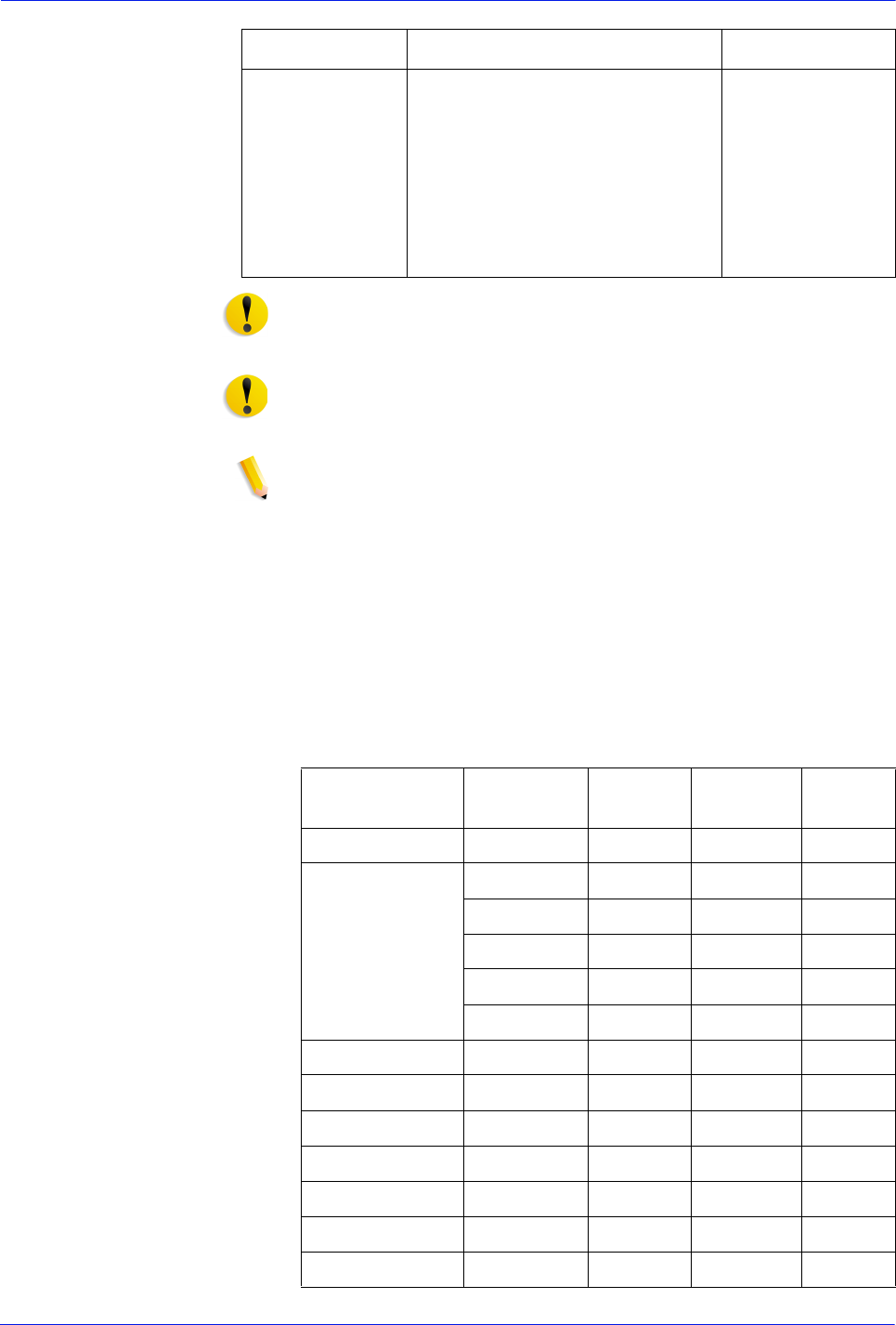
DocuTech 128/155/180 HighLight Color Operator Guide 6-9
Service and supplies
CAUTION: *Do not use DT/DP Fuser Agent 8R2955 in a DT HLC
printer. Do not use DT HLC Fuser Blend in other DocuTech or
DocuPrint systems.
CAUTION: *Fuser blend and Fuser shield are NOT
interchangeable. Contact your Xerox representative before
switching from one to the other.
NOTE: Color developer, the Dry ink waste bottle, and the waste
filter are ordered and stocked by the Xerox Service
Representative for your site. The part numbers are provided here
for informational purposes only.
Use the following table to help record the supplies and
accessories you require, the date on which the order should be
placed, and the actual date of the order.
Table 6-2. Supplies checklist
Binder Tape Black
White
Gray
Blue
Packaged 1 reel per carton.
Consumption rate is
approximately 425 binds per
carton.
8R7186
8R7187
8R7188
8R7189
Item Description U.S. part number
Item Description Quantity Date of
order
Date
ordered
Paper
Dry ink
Developer

6-10 DocuTech 128/155/180 HighLight Color Operator Guide
Service and supplies
Fuser shield
Labels
Transparencies
Cleaning supplies
Other
Item Description Quantity Date of
order
Date
ordered

DocuTech 128/155/180 HighLight Color Operator Guide 6-11
Service and supplies
If you use custom colors, use the following table to help record the
supplies and accessories you require, the date on which the order
should be placed, and the actual date of the order.
Table 6-3. Custom Color Supplies checklist
Item Description Quantity Date of
order
Date
ordered
Dry ink
Developer

6-12 DocuTech 128/155/180 HighLight Color Operator Guide
Service and supplies
