Xetawave 93829283-MSD9 MSD9 User Manual Exhibit D Users Manual per 2 1033 c3
Xetawave LLC MSD9 Exhibit D Users Manual per 2 1033 c3
Xetawave >
Contents
- 1. Exhibit D Users Manual per 2 1033 c3
- 2. Exhibit D Users Manual per 2 1033 b3
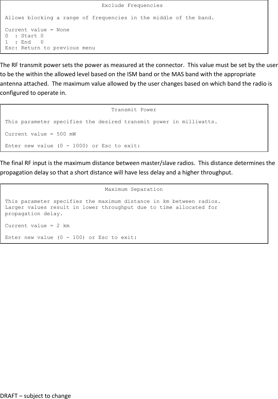
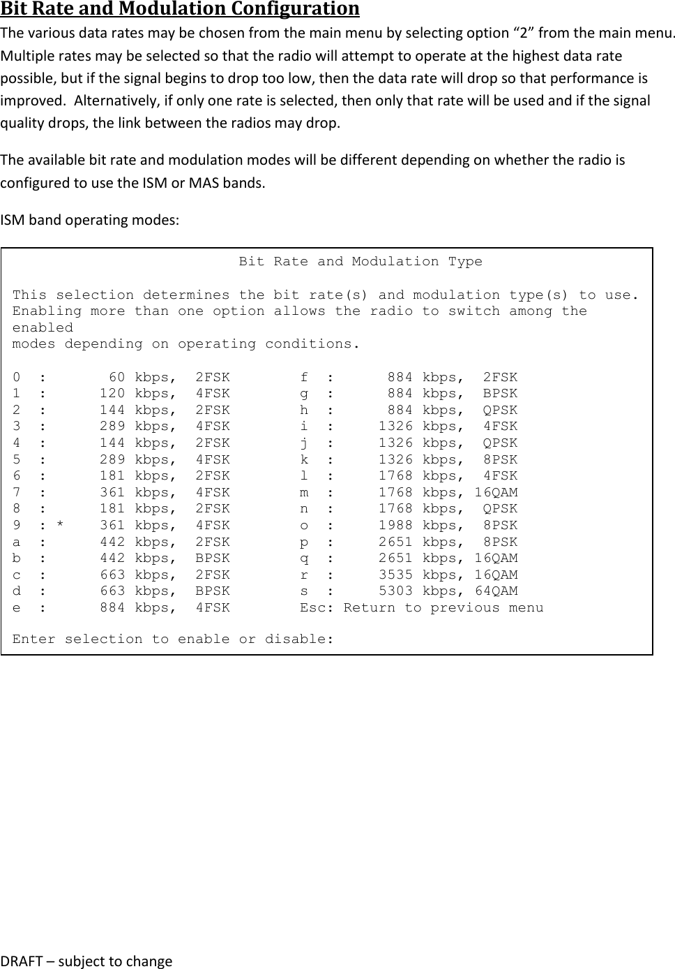
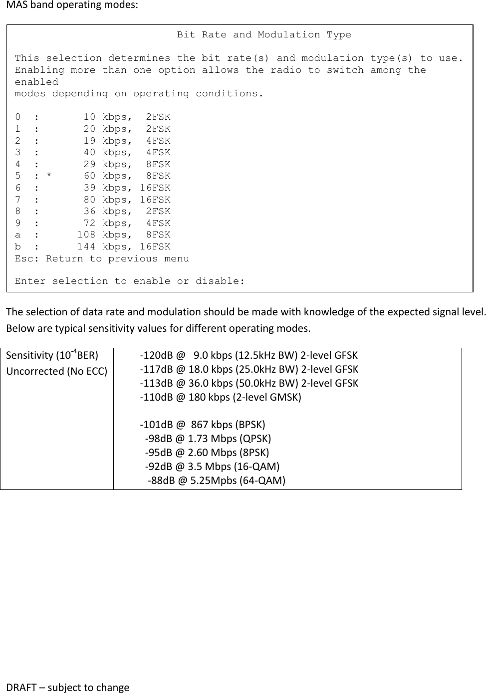
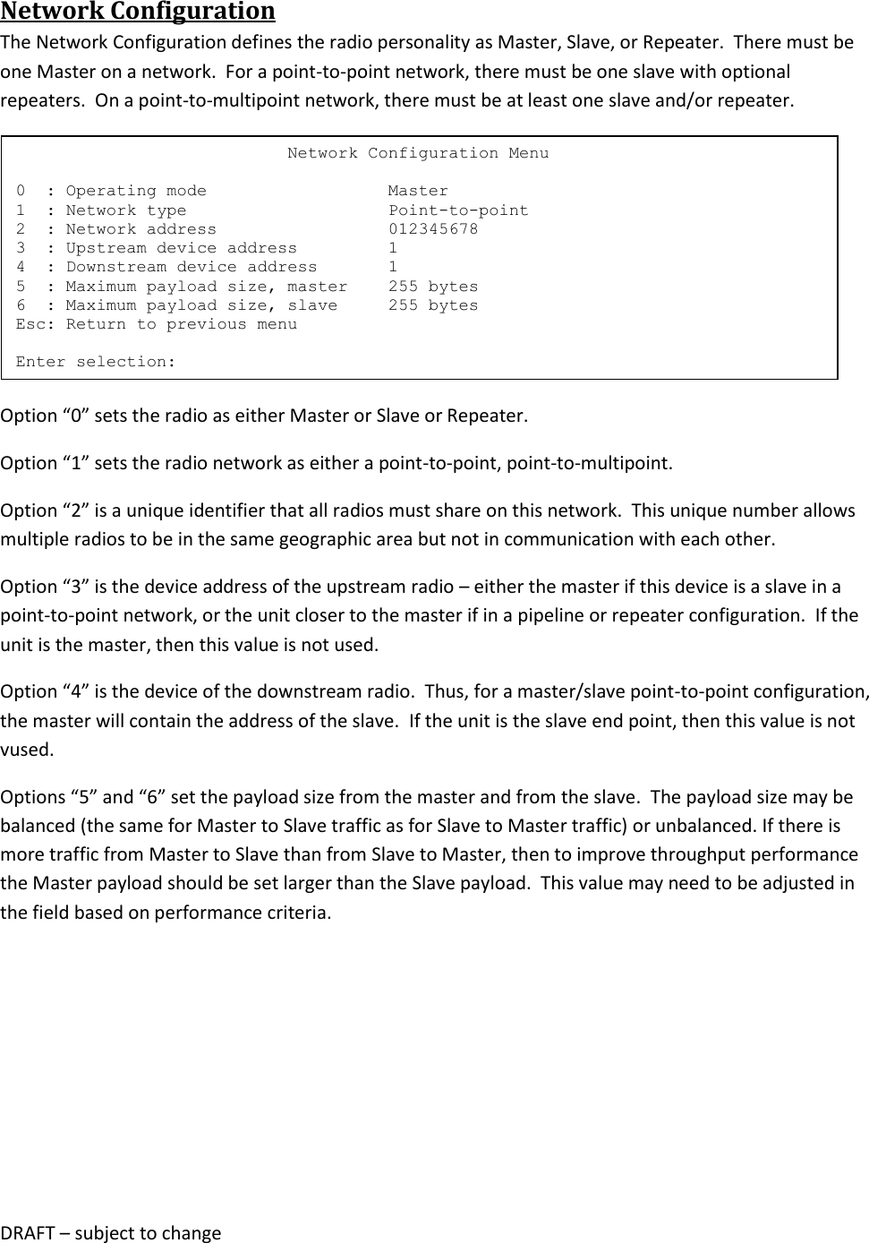
Exhibit D Users Manual per 2 1033 c3