Xi an NovaStar Tech T3 Taurus-MediaPlayer User Manual OEM installation Manual
Xi'an NovaStar Tech Co., Ltd Taurus-MediaPlayer OEM installation Manual
Contents
- 1. Host User Manual
- 2. OEM installation Manual
OEM installation Manual

Taurus Series
Multimedia Players
Quick Start Guide
Version:
V1.0.0
Doc. ID:
NS120100144

Taurus Series Multimedia Players
Quick Start Guide
www.novastar.tech
V1.0.0
i
Change History
Version
Release Date
Description
V1.0.0
2017-07-20
First release.

Taurus Series Multimedia Players
Quick Start Guide
www.novastar.tech
V1.0.0
ii
Table of Contents
Change History................................................................................................................................. i
Table of Contents............................................................................................................................ ii
1Overview.........................................................................................................................................1
1.1 Scenario........................................................................................................................................................................1
1.2 Procedures................................................................................................................................................................... 1
2Preparation.................................................................................................................................... 2
2.1 Getting and Installing Software................................................................................................................................. 2
2.2 Getting Documents..................................................................................................................................................... 3
2.3 Getting Required Account Information.................................................................................................................... 3
3Taurus Connections.................................................................................................................... 4
3.1 Connecting via Ethernet Cable................................................................................................................................. 4
3.2 Connecting via Local Area Network (LAN)............................................................................................................. 4
3.3 Connecting via Wi-Fi.................................................................................................................................................. 5
3.3.1 Wi-Fi AP Mode......................................................................................................................................................... 5
3.3.2 WiFi Sta Mode..........................................................................................................................................................6
3.3.3 WiFi AP+Sta Mode.................................................................................................................................................. 6
4Receiving Card Parameter Configuration............................................................................. 8
4.1 Loading Configuration File or Configuring the Parameters Manually Through NovaLCT-Taurus................. 8
4.2 Loading the Configuration File Through ViPlex Handy.........................................................................................9
5Screen Configuration................................................................................................................10
5.1 Configuring a Screen Through ViPlex Handy...................................................................................................... 10
6General Operations................................................................................................................... 11
6.1 Taurus Login with ViPlex Handy (Android and iOS)........................................................................................... 11
6.2 Taurus Login with ViPlex Express (Windows)......................................................................................................11
7Caution......................................................................................................................................... 13
Taurus Series Multimedia Players
Quick Start Guide
www.novastar.tech
V1.0.0
1
1Overview
1.1 Scenario
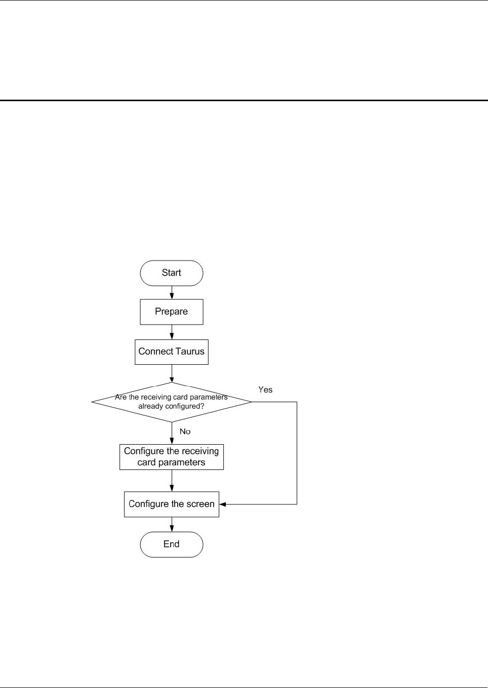
This document introduces a quick way to use Taurus series multimedia players and
provides instructions for the first-timer.
1.2 Procedures

Taurus Series Multimedia Players
Quick Start Guide
www.novastar.tech
V1.0.0
2
2Preparation
2.1 Getting and Installing Software
Item
Description
How to get
How to install
ViPlex Handy
It is a LAN-based
display
management
software, including
the one applicable
to Android and iOS
operating systems,
is mainly used for
display
management as
well as solution
editing and
publishing.
Scan the following
OR code to download
and install the APP.
Use the App Store on
your iPhone to get
ViPlex Handy for iOS.
Software
installation is
the same as
other
applications.
ViPlex Express
It is a LAN-based
display
management
software applicable
to the Windows
operating system,
and is mainly used
for display
management as
well as solution
editing and
publishing.
Visit
www.novastar.tech,
download and install
the required software.
NovaLCT-Taurus
Screen
configuration
software, which only
supports Windows
and is mainly used
for adjusting
screens to the
optimal display
status.
Visit
www.novastar.tech,
download and install
the required software.

Taurus Series Multimedia Players
Quick Start Guide
www.novastar.tech
V1.0.0
3
2.2 Getting Documents
Item
Description
How to get
Taurus Series
Multimedia Players
Product
Description-V1.0.0
Describing application
scenarios, features, safety
instructions, hardware
structure, software structure
and specifications of Taurus
series products.
Visit www.novastar.tech to
download the required
documents.
2.3 Getting Required Account Information
Item
Account Name
Default Password
Connect Taurus WiFi AP
AP+ last 8 digits of the SN,
For example: AP10000033
12345678
Log into the Taurus
admin
123456
Taurus Series Multimedia Players
Quick Start Guide
www.novastar.tech
V1.0.0
4
3Taurus Connections
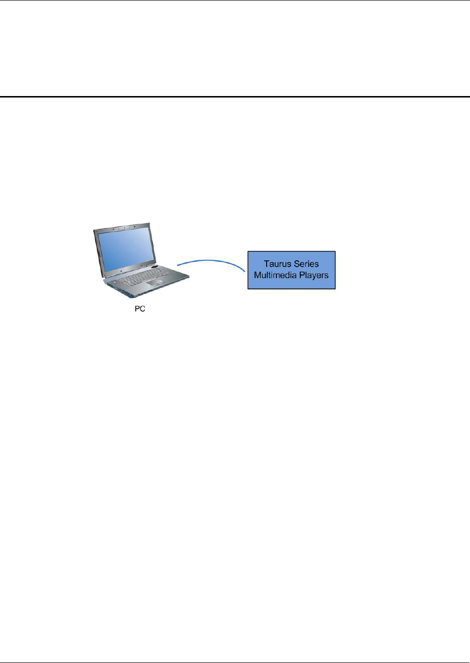
3.1 Connecting via Ethernet Cable
Network Diagram
Users can access the Taurus directly when it is connected via the Ethernet cable.
Configuration
Step 1 Refer to “6 General Operations” to log in to the Taurus.
Step 2 Turn off DHCP and set static IP address for the Taurus.
ViPlex Handy: Select Network Setting,Wired Network Setting in the Screen
management page.
ViPlex Express: Select Screen Control,Network configuration.
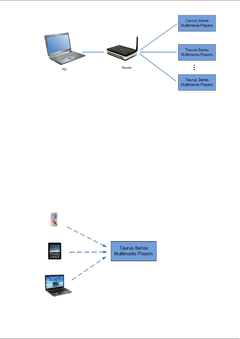
3.2 Connecting via Local Area Network (LAN)
Network Diagram
Users can access the Taurus through LAN when it is connected via LAN.
Taurus Series Multimedia Players
Quick Start Guide
www.novastar.tech
V1.0.0
5
Configuration
No need for configuration.
3.3 Connecting via Wi-Fi
The Taurus series products have dual WiFi function which can provide Wi-Fi hotspot
as well as serve as WiFi Station at the same time. The WiFi working frequency range
is 2400~2483.5MHz.
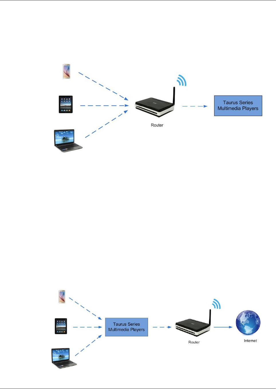
3.3.1 Wi-Fi AP Mode
Network Diagram
Users can access the Taurus directly when it is connected via WiFi AP.
Configuration
No need for configuration. Please connect the WiFi AP of the Taurus. SSID is “AP +
last 8 digits of the SN”, for example, “AP10000033”.
Taurus Series Multimedia Players
Quick Start Guide
www.novastar.tech
V1.0.0
6
3.3.2 WiFi Sta Mode
Network Diagram
Users can access Taurus through external router when it is connected via WiFi Sta.
Configuration
Step 1 Refer to “6 General Operations” to log in to the Taurus.
Step 2 Turn on Wi-Fi Sta mode. Click the Wi-Fi name of the external router and then enter
the password of the Wi-Fi.
ViPlex Handy: Select Network Setting,WiFi Setting in the Screen
management page.
ViPlex Express: Select Screen Control,Network configuration.
3.3.3 WiFi AP+Sta Mode
Network Diagram
By using WiFi AP+Sta connection, users can directly access the Taurus or access the
Internet through bridging connection.

Taurus Series Multimedia Players
Quick Start Guide
www.novastar.tech
V1.0.0
7
Configuration
Step 1 Refer to “6 General Operations” to log in to the Taurus.
Step 2 Turn on Wi-Fi Sta mode. Click the Wi-Fi name of the external router and then enter
the password of the Wi-Fi.
ViPlex Handy: Select Network Setting,WiFi Setting in the Screen
management page.
ViPlex Express: Select Screen Control,Network configuration.
Related Information
The Taurus can be connected to the Internet through following two ways. The priority
order of the three ways is from high to low.
Wired network
WiFi Sta

Taurus Series Multimedia Players
Quick Start Guide
www.novastar.tech
V1.0.0
8
4Receiving Card Parameter Con
figuration
If receiving card parameters are already configured, please skip this chapter and
perform the operations in “5 Screen Configuration”.
4.1 Loading Configuration File or Configuring the
Parameters Manually Through NovaLCT-Taurus
Step 1 Start NovaLCT-Taurus.
Step 2 Select System,Search All Display.
System will display the screen information list.
Step 3 Click screen information and click Connect System.
The gray button on the page will become normal.
Step 4 Select User,Advanced login.
Step 5 Enter password and click Login.
Default password is “admin”.
Step 6 Click to enter the Screen Config page.
Step 7 Confirm whether the local PC has the required receiving card configuration file.
Yes. Please perform Load Configuration File.
No. Please perform Manual Configuration.
Loading Configuration File
Step 1 Select Cascading scan board and Load Configuration File. Click Browse to
choose a configuration file from the local PC.
Step 2 Click Next to load the configuration file.
Manual Configuration
Step 1 Select Cascading scan board and click Next.
Step 2 Configure receiving card parameters based on actual conditions.

Taurus Series Multimedia Players
Quick Start Guide
www.novastar.tech
V1.0.0
9
Step 3 Click Send To HW.
Step 4 Set parameters based on actual conditions and click Send.
Step 5 Adjust parameters until the screen displays normally and then click Save to Screen.
Step 6 (Optional) Click Save Config File to back up the receiving card configuration file to
the local PC.
4.2 Loading the Configuration File Through ViPlex Handy
Step 1 Save the receiving card configuration file to mobile phone.
Step 2 Refer to “6 General Operations” to log in to the Taurus.
Step 3 Click screen name to enter the Screen management page.
Step 4 Select Screen Setting,Receiving card configuration to enter the Receiving card
configuration page.
Step 5 Select the receiving card configuration file and click Send.

Taurus Series Multimedia Players
Quick Start Guide
www.novastar.tech
V1.0.0
10
5Screen Configuration
5.1 Configuring a Screen Through ViPlex Handy
Step 1 Refer to “6 General Operations” to log in to the Taurus.
Step 2 Click screen name to enter the Screen management page.
Step 3 Select Screen Setting,Screen configuration to enter the Screen configuration
page.
Step 4 Configure screen information based on actual conditions and click OK.

Taurus Series Multimedia Players
Quick Start Guide
www.novastar.tech
V1.0.0
11
6General Operations
6.1 Taurus Login with ViPlex Handy (Android and iOS)
Before You Begin
Acquire the SSID and password of Wi-Fi AP of Taurus series products. SSID is
default to be composed of AP and the last 8 numbers of SN, and the password is
default as “12345678”.
Acquire the login password of user “admin” of which the default password is
“123456”.
Operating Procedures
ViPlex Handy can connect numerous Taurus series products.
Step 1 Connect Wi-Fi AP of the Taurus series products.
Step 2 Start ViPlex Handy.
System can automatically detect the Taurus series products and refresh Screen list.
Users can also slide down Screen list to manually refresh the list.
: denotes that Taurus is online and you can log into it.
: denotes that Taurus is offline and you cannot log into it.
: denotes that Taurus login is successful.
Step 3 Click Connect next to the screen name.
Step 4 Enter the user name and password and click Login.
6.2 Taurus Login with ViPlex Express (Windows)
Before You Begin
Acquire the SSID and password of Wi-Fi AP of Taurus series products. SSID is
default to be composed of AP and the last 8 numbers of SN, and the password is
default as “12345678”.
Acquire the login password of user “admin” of which the default password is
“123456”.

Taurus Series Multimedia Players
Quick Start Guide
www.novastar.tech
V1.0.0
12
Operating Procedures
ViPlex Express can connect numerous Taurus series products.
Step 1 Connect Wi-Fi AP of the Taurus series products.
Step 2 Start the ViPlex Express.
Step 3 Click Refresh and the screen list will be displayed on the page.
: denotes that Taurus is online and you can log into it.
: denotes that Taurus is offline and you cannot log into it.
: denotes that Taurus login is successful.
After the Taurus is found by ViPlex Express, the ViPlex express will try to log into to
the Taurus with the default account or the account used for last login.
Step 4 Taurus login is successful or not.
Yes. appears and no further operation is required.
No. appears and then perform Step 5.
Step 5 Click Connect on the right of the screen information.
Step 6 Enter the username and password, and click OK.

Taurus Series Multimedia Players
Quick Start Guide
www.novastar.tech
V1.0.0
13
7Caution
FCC Caution:
Any changes or modifications not expressly approved by the party responsible for compliance could
void the user's authority to operate the equipment.
This device complies with part 15 of the FCC Rules. Operation is subject to the following two conditions:
(1) This device may not cause harmful interference, and (2) this device must accept any interference
received, including interference that may cause undesired operation.
Note: This equipment has been tested and found to comply with the limits for a Class A digital device,
pursuant to part 15 of the FCC Rules. These limits are designed to provide reasonable protection
against harmful interference when the equipment is operated in a commercial environment. This
equipment generates, uses, and can radiate radio frequency energy and, if not installed and used in
accordance with the instruction manual, may cause harmful interference to radio communications.
Operation of this equipment in a residential area is likely to cause harmful interference in which case the
user will be required to correct the interference at his own expense.
This equipment complies with FCC radiation exposure limits set forth for an uncontrolled
environment .This equipment should be installed and operated with minimum distance 20cm between
the radiator & your body.
This transmitter must not be co-located or operating in conjunction with any other antenna or transmitter.
CE Caution:
This equipment should be installed and operated with minimum distance 20cm between the radiator &
your body.
IC Warning:
RSS-Gen Issue 3 December 2010"&"CNR-Gen 3e éditionDécembre 2010:
- English:
This device complies with Industry Canada licence-exempt RSS standard(s).
Operation is subject to the following two conditions: (1) This device may not cause interference, and (2)
This device must accept any interference, including interference that may cause undesired operation of
the device.
- French:
Le présentappareilestconforme aux CNR d'Industrie Canada applicables aux appareils radio exempts
de licence. L'exploitationestautorisée aux deux conditions suivantes:
(1) l'appareil ne doit pas produire de brouillage, et

Taurus Series Multimedia Players
Quick Start Guide
www.novastar.tech
V1.0.0
14
(2) l'utilisateur de l'appareildoit accepter tout brouillageradioélectriquesubi, mêmesi le brouillageest
susceptible d'encompromettre le fonctionnement.
Battery Caution:

AMPAK Technology Inc. www.ampak.com.tw Proprietary & Confidential Information
Doc. NO:
正基
正基正基
正基科技股份有限公司
科技股份有限公司科技股份有限公司
科技股份有限公司
SPECIFICATION
SPEC. NO.:
::
: REV: 1.3
DATE:
::
: 12. 26.2014
PRODUCT NAME:
::
: AP6212
APPROVED CHECKED PREPARED DCC ISSUE
NAME

AMPAK Technology Inc. www.ampak.com.tw Proprietary & Confidential Information
Doc. NO:
AMPAK
AP6212
WiFi+Bluetooth 4.1+FM RX
SIP Module Spec Sheet

AMPAK Technology Inc. www.ampak.com.tw Proprietary & Confidential Information
Doc. NO:
1
Revision History
Date Revision Content Revised By
Version
2014/04/08 - Preliminary Brian 1.0
2014/09/02 - Pin Definition Modified Brian 1.1
2014/11/26 - Bluetooth Spec Modified Brian 1.2
2014/12/26 - Add Process Brian 1.3

AP6212 Datasheet
AMPAK Technology Inc. www.ampak.com.tw Proprietary & Confidential Information
Doc. NO:
2
Contents
Contents ................................................................................................................... 2
1. Introduction ......................................................................................................... 3
2. Features............................................................................................................... 4
3. Deliverables ........................................................................................................ 5
3.1 Deliverables .................................................................................................... 5
3.2 Regulatory certifications ................................................................................. 5
4. General Specification ......................................................................................... 6
4.1 General Specification ...................................................................................... 6
4.2 Voltages .......................................................................................................... 6
4.2.1 Absolute Maximum Ratings .................................................................... 6
4.2.2 Recommended Operating Rating ........................................................... 6
5. WiFi RF Specification ......................................................................................... 7
5.1 2.4GHz RF Specification................................................................................. 7
6. Bluetooth Specification ...................................................................................... 9
6.1 Bluetooth Specification ................................................................................... 9
7. FM Specification ............................................................................................... 10
7.1 FM Specification (TBD) ................................................................................. 10
8. Pin Assignments ............................................................................................... 11
8.1 Pin Outline .................................................................................................... 11
8.2 Pin Definition ................................................................................................ 11
9. Dimensions ....................................................................................................... 13
9.1 Physical Dimensions .................................................................................... 13
9.2 Layout Recommendation .............................................................................. 14
10. External clock reference .................................................................................. 15
10.1 SDIO Pin Description .................................................................................. 15
11. Host Interface Timing Diagramo ..................................................................... 16
11.1 Power-up Sequence Timing Diagram ......................................................... 16
11.2 SDIO Default Mode Timing Diagram ........................................................... 18
11.3 SDIO High Speed Mode Timing Diagram .................................................... 19
12. Recommended Reflow Profile ......................................................................... 20
13. Package Information ........................................................................................ 22
13.1Label .......................................................................................................... 22
13.2 Dimension ................................................................................................. 23
13.3 MSL Level / Storage Condition ................................................................... 25

AP6212 Datasheet
AMPAK Technology Inc. www.ampak.com.tw Proprietary & Confidential Information
Doc. NO:
3
1. Introduction
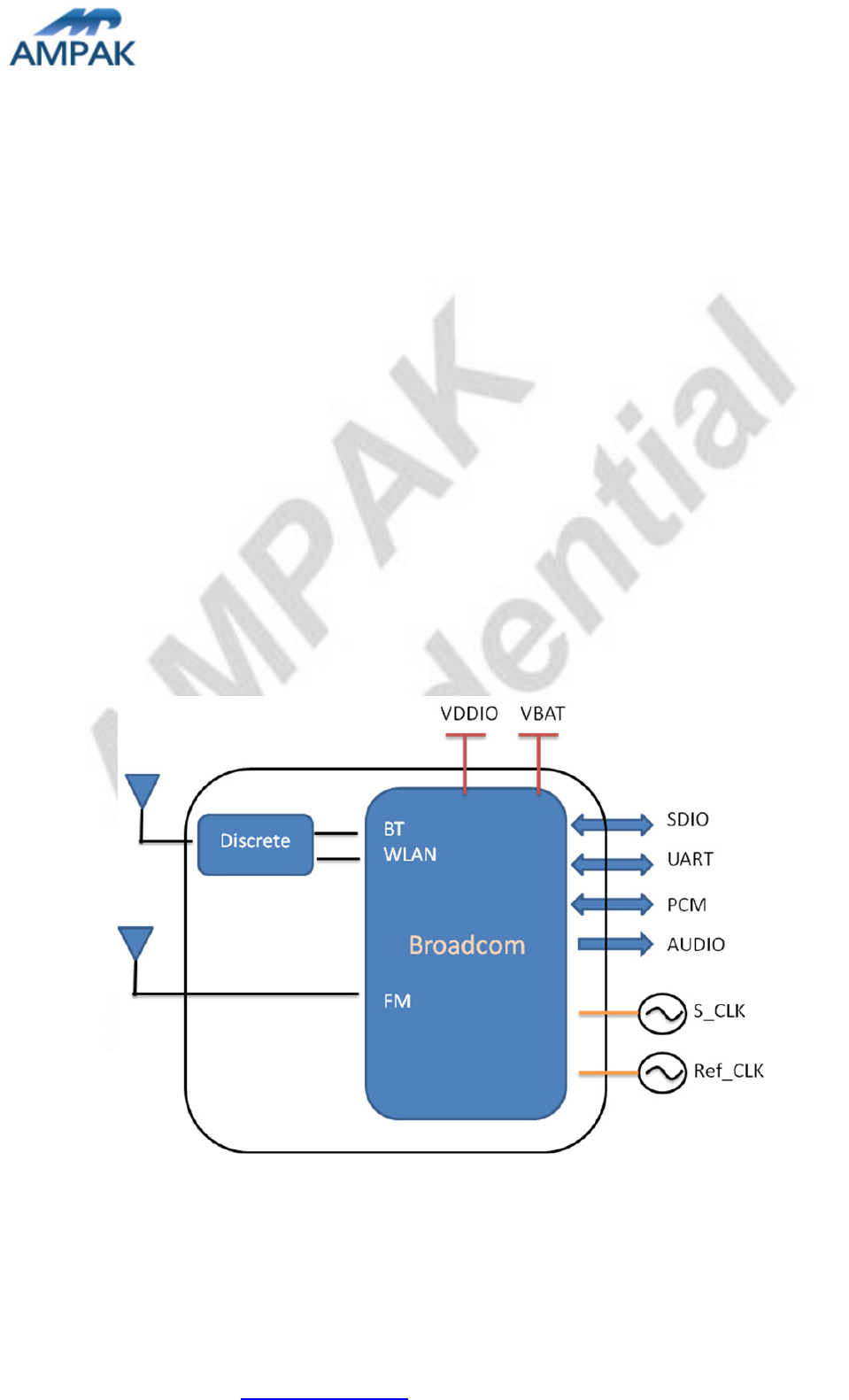
AMPAK Technology would like to announce a low-cost and low-power consumption module
which has all of the WiFi, Bluetooth and FM functionalities. The highly integrated module
makes the possibilities of web browsing, VoIP, Bluetooth headsets, FM radio functional
applications and other applications. With seamless roaming capabilities and advanced
security, also could interact with different vendors’ 802.11b/g/n Access Points in the wireless
LAN.
The wireless module complies with IEEE 802.11 b/g/n standard and it can achieve up to a
speed of 72.2Mbps with single stream in 802.11n draft, 54Mbps as specified in IEEE
802.11g, or 11Mbps for IEEE 802.11b to connect to the wireless LAN. The integrated
module provides SDIO interface for WiFi, UART / I2S / PCM interface for Bluetooth and
UART / I2S / PCM interface for FM.
This compact module is a total solution for a combination of WiFi + BT + FM technologies.
The module is specifically developed for Smart phones and Portable devices.
AP6212 Datasheet
AMPAK Technology Inc. www.ampak.com.tw Proprietary & Confidential Information
Doc. NO:
4
2. Features
802.11b/g/n single-band radio
Bluetooth V4.1(HS) with integrated Class 1.5 PA and Low Energy (BLE) support
Concurrent Bluetooth, FM (RX) RDS/RBDS, and WLAN operation
Simultaneous BT/WLAN receive with single antenna
WLAN host interface options:
- SDIO v2.0 — up to 50 MHz clock rate
BT host digital interface:
- UART (up to 4 Mbps)
FM multiple audio routing options: I2S, PCM, eSCO, A2DP
IEEE Co-existence technologies are integrated die solution
ECI — enhanced coexistence support, ability to coordinate BT SCO transmissions
around WLAN receives
A simplified block diagram of the module is depicted in the figure below.

AP6212 Datasheet
AMPAK Technology Inc. www.ampak.com.tw Proprietary & Confidential Information
Doc. NO:
5
3. Deliverables
3.1 Deliverables
The following products and software will be part of the product.
Module with packaging
Evaluation Kits
Software utility for integration, performance test.
Product Datasheet.
Agency certified pre-tested report with the adapter board.
3.2 Regulatory certifications
The product delivery is a pre-tested module, without the module level certification.
For module approval, the platform’s antennas are required for the certification.

AP6212 Datasheet
AMPAK Technology Inc. www.ampak.com.tw Proprietary & Confidential Information
Doc. NO:
6
4. General Specification
4.1 General Specification
4.2 Voltages
4.2.1 Absolute Maximum Ratings
Symbol Description Min.
Max.
Unit
VBAT Input supply Voltage -0.5
5.5 V
WL_VIO_SD Digital/Bluetooth/SDIO/ I/O Voltage -0.5
3.6 V
4.2.2 Recommended Operating Rating
The module requires two power supplies: VBAT and VDDIO.
Min. Typ. Max. Unit
Operating Temperature -30 25 85 deg.C
VBAT 3.0 3.6 4.8 V
VDDIO 1.7 3.3 3.6 V
Model Name AP6212
Product Description Support WiFi/Bluetooth/FM functionalities
Dimension L x W x H: 12 x 12 x 1.5 (typical) mm
WiFi Interface SDIOV2.0
BT Interface UART / PCM
FM Interface UART / PCM / Audio
Operating temperature
-30°C to 85°C
Storage temperature -40°C to 85°C
Humidity Operating Humidity 10% to 95% Non-Condensing
Storage Humidity 5% to 95% Non
-
Condensi
ng

AP6212 Datasheet
AMPAK Technology Inc. www.ampak.com.tw Proprietary & Confidential Information
Doc. NO:
7
5. WiFi RF Specification
5.1 2.4GHz RF Specification
Conditions : VBAT=3.6V ; VDDIO=3.3V ; Temp:25°C
Feature Description
WLAN Standard IEEE 802.11b/g/n, WiFi compliant
Frequency Range 2.400 GHz ~ 2.497 GHz (2.4 GHz ISM Band)
Number of Channels 2.4GHz:Ch1 ~ Ch14
Modulation 802.11b : DQPSK, DBPSK, CCK
802.11 g/n : OFDM /64-QAM,16-QAM, QPSK, BPSK
Output Power
802.11b /11Mbps : 16 dBm ± 1.5 dB @ EVM ≤ -9dB
802.11g /54Mbps : 15 dBm ± 1.5 dB @ EVM ≤ -25dB
802.11n /65Mbps : 14 dBm ± 1.5 dB @ EVM ≤ -28dB
Receive Sensitivity
(11n,20MHz)
@10% PER
- MCS=0 PER @ -85 dBm, typical
- MCS=1 PER @ -84 dBm, typical
- MCS=2 PER @ -82 dBm, typical
- MCS=3 PER @ -80 dBm, typical
- MCS=4 PER @ -77 dBm, typical
- MCS=5 PER @ -73 dBm, typical
- MCS=6 PER @ -71 dBm, typical
- MCS=7 PER @ -68 dBm, typical
Receive Sensitivity (11g)
@10% PER
- 6Mbps PER @ -86 dBm, typical
- 9Mbps PER @ -85 dBm, typical
- 12Mbps PER @ -85 dBm, typical
- 18Mbps PER @ -83 dBm, typical
- 24Mbps PER @ -81 dBm, typical
- 36Mbps PER @ -78 dBm, typical
- 48Mbps PER @ -73 dBm, typical
- 54Mbps PER @ -71 dBm, typical
Receive Sensitivity (11b)
@8% PER
- 1Mbps PER @ -90 dBm, typical
- 2Mbps PER @ -88 dBm, typical
- 5.5Mbps PER @ -87 dBm, typical
- 11Mbps PER @ -84 dBm, typical
Data Rate 802.11b : 1, 2, 5.5, 11Mbps
802.11g : 6, 9, 12, 18, 24, 36, 48, 54Mbps

AP6212 Datasheet
AMPAK Technology Inc. www.ampak.com.tw Proprietary & Confidential Information
Doc. NO:
8
Data Rate
(20MHz ,Long GI,800ns)
802.11n: 6.5, 13, 19.5, 26, 39, 52, 58.5, 65Mbps
Data Rate
(20MHz ,short GI,400ns)
802.11n : 7.2, 14.4, 21.7, 28.9, 43.3, 57.8, 65,72.2Mbps
Maximum Input Level 802.11b : -10 dBm
802.11g/n : -20 dBm
Antenna Reference Small antennas with 0~2 dBi peak gain

AP6212 Datasheet
AMPAK Technology Inc. www.ampak.com.tw Proprietary & Confidential Information
Doc. NO:
9
6. Bluetooth Specification
6.1 Bluetooth Specification
Conditions : VBAT=3.6V ; VDDIO=3.3V ; Temp:25°C
Feature Description
General Specification
Bluetooth Standard Bluetooth V4.1 of 1, 2 and 3 Mbps.
Host Interface UART
Antenna Reference Small antennas with 0~2 dBi peak gain
Frequency Band 2402MHz ~ 2480MHz
Number of Channels 79 channels
Modulation FHSS, GFSK, DPSK, DQPSK
RF Specification
Min. Typical. Max.
Output Power (Class 1.5) 8 dBm
Sensitivity @ BER=0.1%
for GFSK (1Mbps) -86 dBm
Sensitivity @ BER=0.01%
for π/4-DQPSK (2Mbps) -86 dBm
Sensitivity @ BER=0.01%
for 8DPSK (3Mbps) -80 dBm
Maximum Input Level
GFSK (1Mbps):-20dBm
π/4-DQPSK (2Mbps) :-20dBm
8DPSK (3Mbps) :-20dBm
AP6212 Datasheet
AMPAK Technology Inc. www.ampak.com.tw Proprietary & Confidential Information
Doc. NO:
10
7. FM Specification
7.1 FM Specification (TBD)
Conditions : VBAT=3.6V ; VDDIO=3.3V ; Temp:25°C
Feature Description
General Specification
Frequency Band 76MHz-108MHz
Host Interface HCI UART, I2S/PCM
Channel step 50 KHz
Analog Audio output load
RL>30KΩ, CL>20pF
Characteristics Condition MIN
TYP
MAX
UNIT
Transmitter
(FM Tx load = 120nH,
Q>30)
Output Power Level dBuV
Audio harmonic distortion
(fmod=1KHz, △f=75KHz,
Pilot △f=6.75KHz)
%
Audio SNR
(△f=22.5KHz, I2S
audio in SNR ≧
57dB )
MONO
dB
Stereo
Receiver
(FM Tx Antenna =
120nH, Q>30)
RDS Sensitivity dBm
Audio harmonic
distortion
(Vin=1mV, △f=75KHz)
fmod=
1KHz
%
fmod=
3KHz
Maximum SNR
(fmod=1KHz, f=22.5
KHz, BW=300Hz to
15KHz)
MONO
dB
Stereo
RF input power level dBuV
AP6212 Datasheet
AMPAK Technology Inc. www.ampak.com.tw Proprietary & Confidential Information
Doc. NO:
11
8. Pin Assignments
8.1 Pin Outline
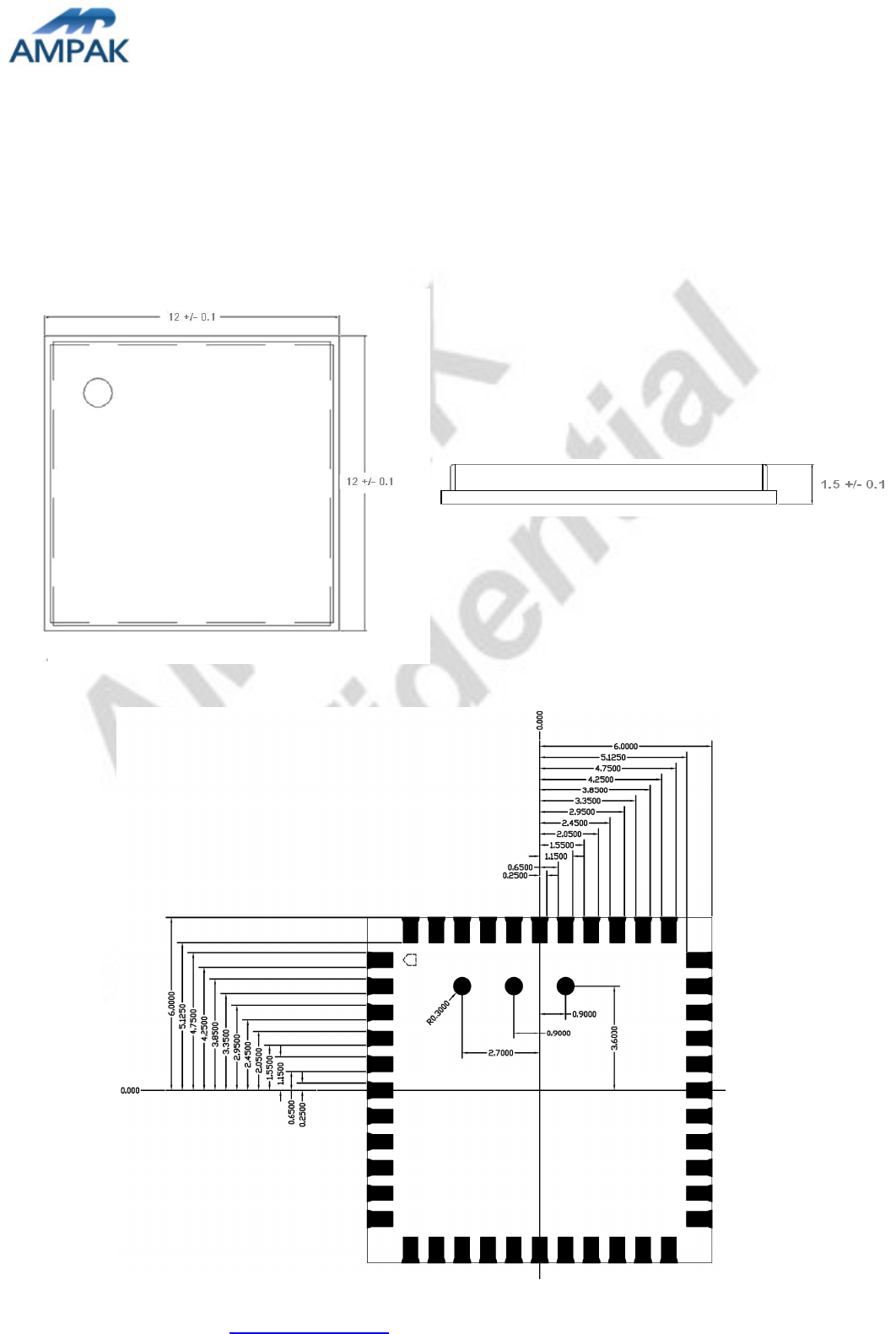
< TOP VIEW >
8.2 Pin Definition
NO
Name Type
Description
1 GND - Ground connections
2 WL_BT_ANT I/O
RF I/O port
3 GND - Ground connections
4 FM_RX I FM radio RF input antenna port
5 NC - Floating (Don’t connected to ground)
6 BT_WAKE I HOST wake-up Bluetooth device
7 BT_HOST_WAKE O Bluetooth device to wake-up HOST
8 NC - Floating (Don’t connected to ground)
9 VBAT P Main power voltage source input
10
XTAL_IN I Crystal input
11
XTAL_OUT O Crystal output
12
WL_REG_ON I Internal regulators power enable/disable
13
WL_HOST_WAKE O WLAN to wake-up HOST

AP6212 Datasheet
AMPAK Technology Inc. www.ampak.com.tw Proprietary & Confidential Information
Doc. NO:
12
14
SDIO_DATA_2 I/O
SDIO data line 2
15
SDIO_DATA_3 I/O
SDIO data line 3
16
SDIO_DATA_CMD I/O
SDIO command line
17
SDIO_DATA_CLK I/O
SDIO clock line
18
SDIO_DATA_0 I/O
SDIO data line 0
19
SDIO_DATA_1 I/O
SDIO data line 1
20
GND - Ground connections
21
VIN_LDO_OUT P Internal Buck voltage generation pin
22
VDDIO P I/O Voltage supply input
23
VIN_LDO P Internal Buck voltage generation pin
24
LPO I External Low Power Clock input (32.768KHz)
25
PCM_OUT O PCM Data output
26
PCM_CLK I/O
PCM clock
27
PCM_IN I PCM data input
28
PCM_SYNC I/O
PCM sync signal
29
NC - Floating (Don’t connected to ground)
30
NC - Floating (Don’t connected to ground)
31
GND - Ground connections
32
NC - Floating (Don’t connected to ground)
33
GND - Ground connections
34
BT_RST_N I Low asserting reset for Bluetooth core
35
NC - Floating (Don’t connected to ground)
36
GND - Ground connections
37
GPIO4 I/O
WiFi Co-existence pin with LTE
38
GPIO3 I/O
WiFi Co-existence pin with LTE
39
GPIO2 I/O
WiFi Co-existence pin with LTE
40
GPIO1 I/O
WiFi Co-existence pin with LTE
41
UART_RTS_N O Bluetooth/FM UART interface
42
UART_TXD O Bluetooth/FM UART interface
43
UART_RXD I Bluetooth/FM UART interface
44
UART_CTS_N I Bluetooth/FM UART interface
45
TP1 O FM Analog AUDIO left output
46
TP2 O FM Analog AUDIO right output
47
TP3 (NC) - Floating (Don’t connected to ground)
AP6212 Datasheet
AMPAK Technology Inc. www.ampak.com.tw Proprietary & Confidential Information
Doc. NO:
13
9. Dimensions
9.1 Physical Dimensions
(Unit: mm)
< TOP VIEW > < Side View >
< TOP VIEW >
AP6212 Datasheet
AMPAK Technology Inc. www.ampak.com.tw Proprietary & Confidential Information
Doc. NO:
14
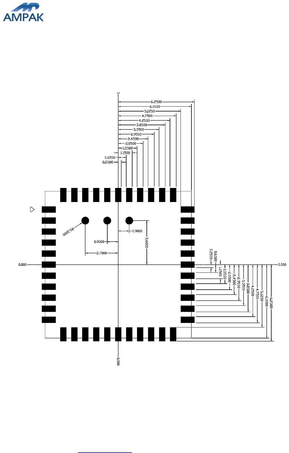
9.2 Layout Recommendation
(Unit: mm)
< TOP VIEW >
AP6212 Datasheet
AMPAK Technology Inc. www.ampak.com.tw Proprietary & Confidential Information
Doc. NO:
15
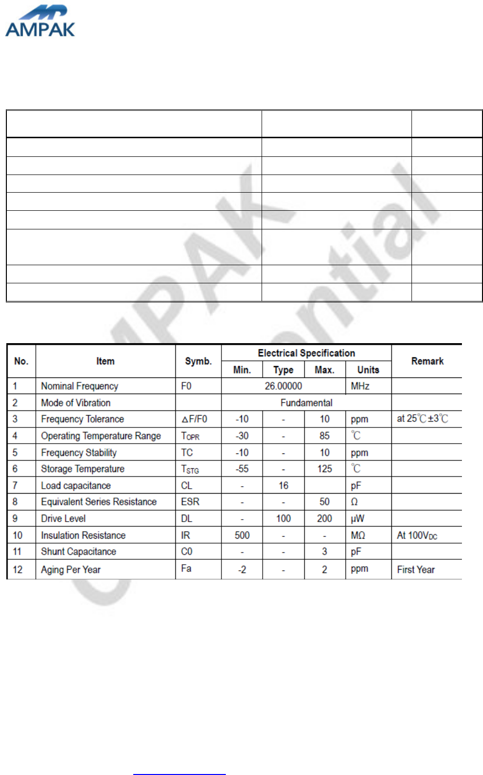
10. External clock reference
External LPO signal characteristics
Parameter Specification Units
Nominal input frequency 32.768 kHz
Frequency accuracy 30
±
ppm
Duty cycle 30 - 70 %
Input signal amplitude 400 to 1800 mV, p-p
Signal type Square-wave -
Input impedance >100k
<5
Ω
pF
Clock jitter (integrated over 300Hz – 15KHz) <1 Hz
Output high voltage 0.7Vio - Vio V
External Ref_CLK signal characteristics
10.1 SDIO Pin Description
The module supports SDIO version 2.0 for 4-bit modes (100 Mbps), and high speed 4-bit (50
MHz clocks – 200 Mbps). It has the ability to stop the SDIO clock and map the interrupt
signal into a GPIO pin. This ‘out-of-band’ interrupt signal notifies the host when the WLAN
device wants to turn on the SDIO interface. The ability to force the control of the gated
clocks from within the WLAN chip is also provided.

AP6212 Datasheet
AMPAK Technology Inc. www.ampak.com.tw Proprietary & Confidential Information
Doc. NO:
16
Function 0 Standard SDIO function (Max BlockSize / ByteCount = 32B)
Function 1 Backplane Function to access the internal System On Chip (SOC)
address space (Max BlockSize / ByteCount = 64B)
Function 2 WLAN Function for efficient WLAN packet transfer through DMA (Max
BlockSize/ByteCount=512B)
SDIO Pin Description
SD 4-Bit Mode
DATA0
Data Line 0
DATA1
Data Line 1 or Interrupt
DATA2
Data Line 2 or Read Wait
DATA3
Data Line 3
CLK Clock
CMD Command Line
11. Host Interface Timing Diagram
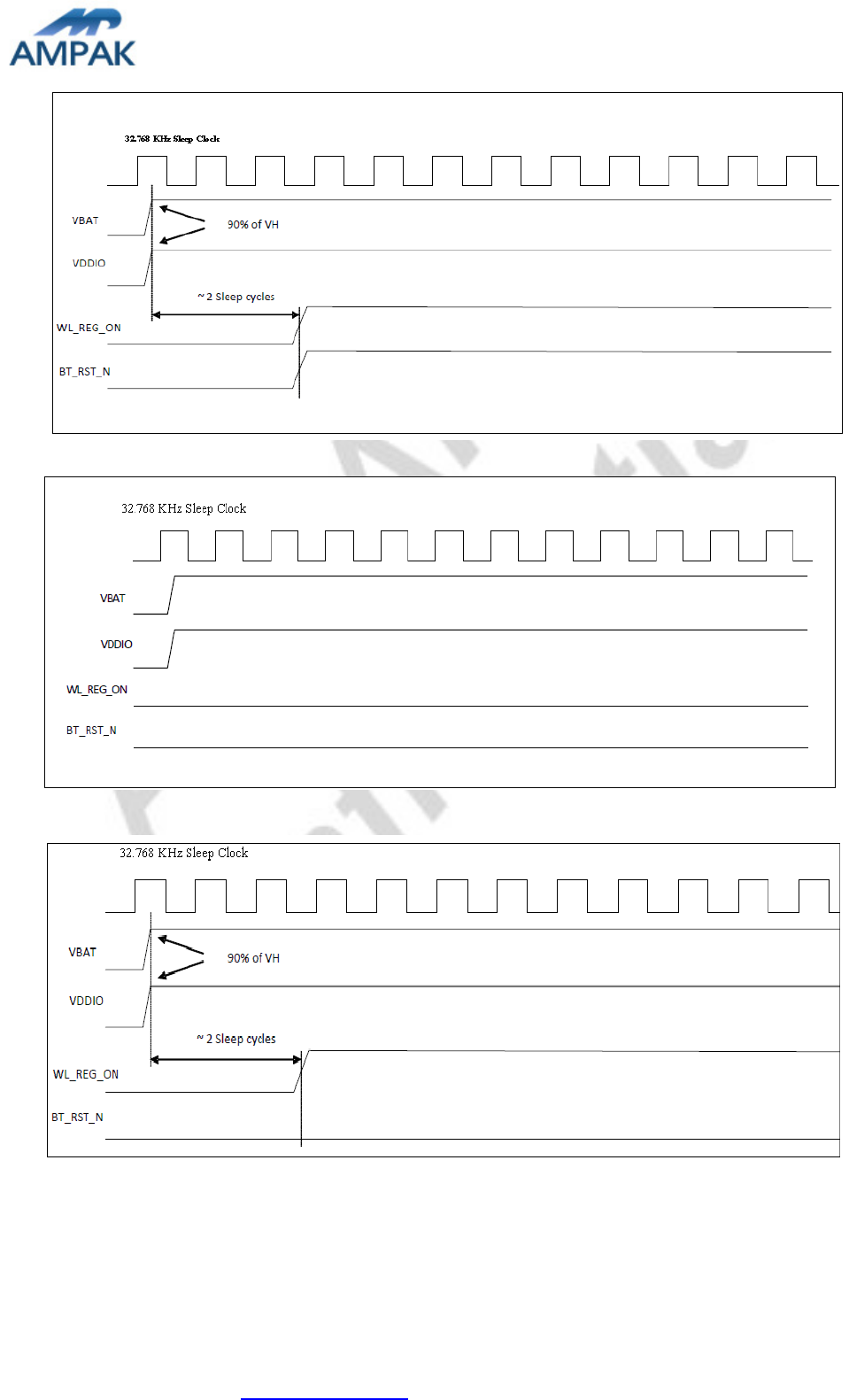
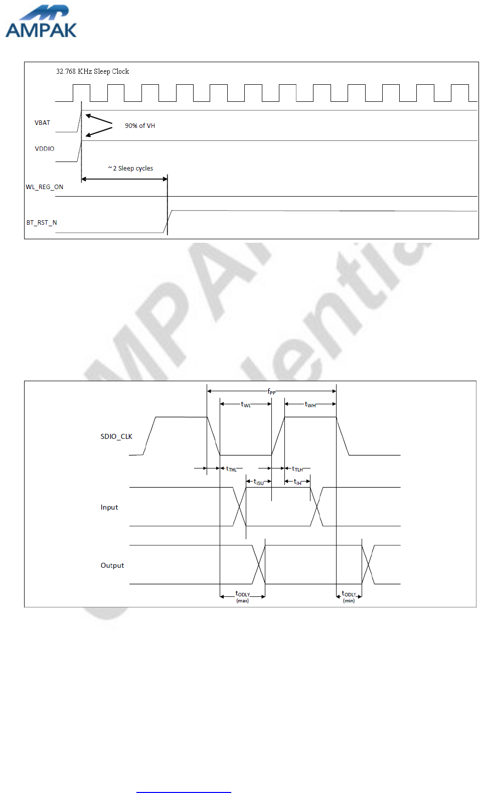
11.1 Power-up Sequence Timing Diagram
The module has signals that allow the host to control power consumption by enabling or
disabling the Bluetooth, WLAN and internal regulator blocks. These signals are described
below.
Additionally, diagrams are provided to indicate proper sequencing of the signals for carious
operating states. The timing value indicated are minimum required values: longer delays are
also acceptable.
※ WL_REG_ON: Used by the PMU to power up the WLAN section. When this pin is
high, the regulators are enabled and the WLAN section is out of reset. When this
pin is low the WLAN section is in reset.
※ BT_RST_N: Low asserting reset for Bluetooth and FM only. This pin has no effect
on WLAN and does not control any PMU functions. This pin must be driven high or
low (not left floating).
AP6212 Datasheet
AMPAK Technology Inc. www.ampak.com.tw Proprietary & Confidential Information
Doc. NO:
17
WLAN=ON, Bluetooth=ON
WLAN=OFF, Bluetooth=OFF
WLAN=ON, Bluetooth=OFF
AP6212 Datasheet
AMPAK Technology Inc. www.ampak.com.tw Proprietary & Confidential Information
Doc. NO:
18
WLAN=OFF, Bluetooth=ON
11.2 SDIO Default Mode Timing Diagram
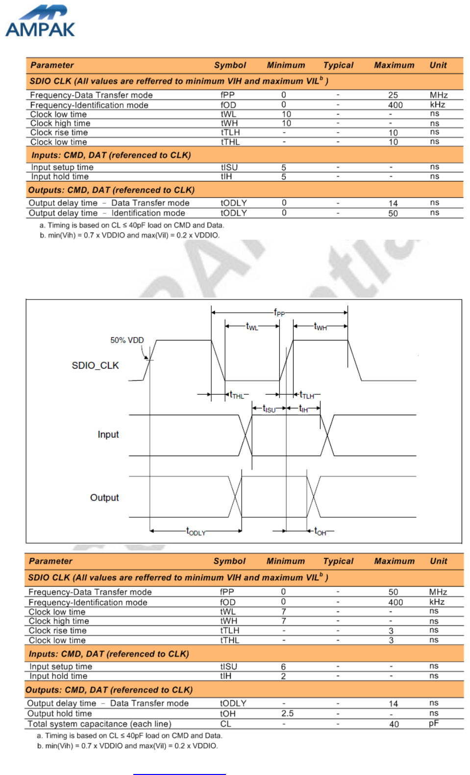
AP6212 Datasheet
AMPAK Technology Inc. www.ampak.com.tw Proprietary & Confidential Information
Doc. NO:
19
11.3 SDIO High Speed Mode Timing Diagram

AP6212 Datasheet
AMPAK Technology Inc. www.ampak.com.tw Proprietary & Confidential Information
Doc. NO:
20
12. Recommended Reflow Profile
Referred to IPC/JEDEC standard.
Peak Temperature : <250°C
Number of Times : ≤2 times
2.5 /sec
2.5
°
C
/sec
40~70 sec
2
50
AP6212 Datasheet
AMPAK Technology Inc. www.ampak.com.tw Proprietary & Confidential Information
Doc. NO:
21
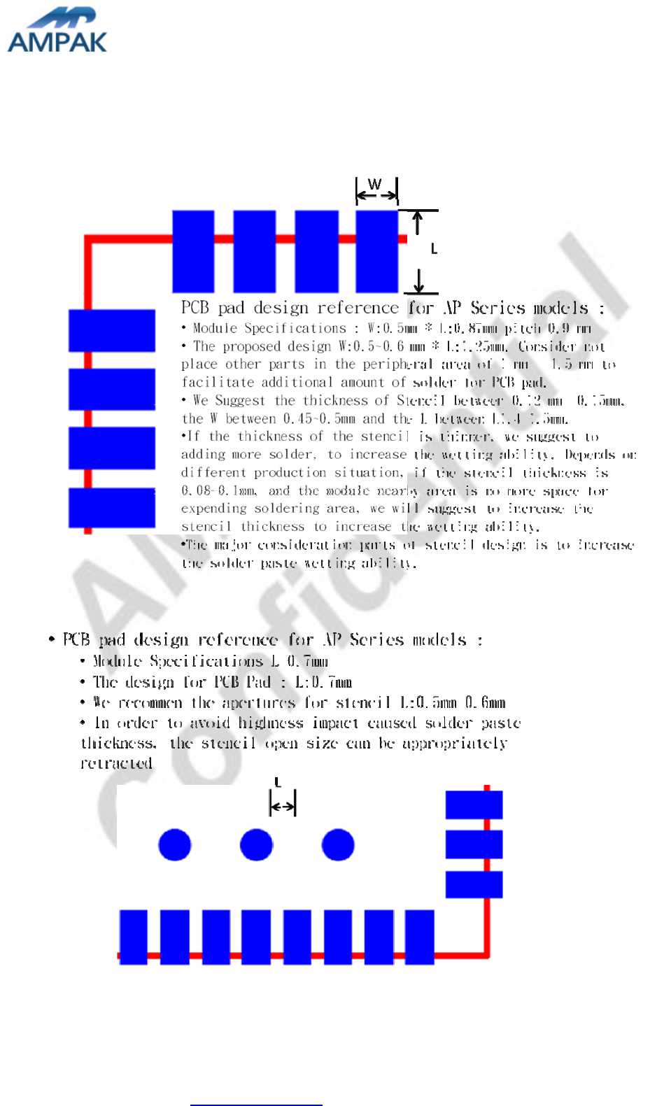
Solder Paste definition
AP6212 Datasheet
AMPAK Technology Inc. www.ampak.com.tw Proprietary & Confidential Information
Doc. NO:
22
13. Package Information
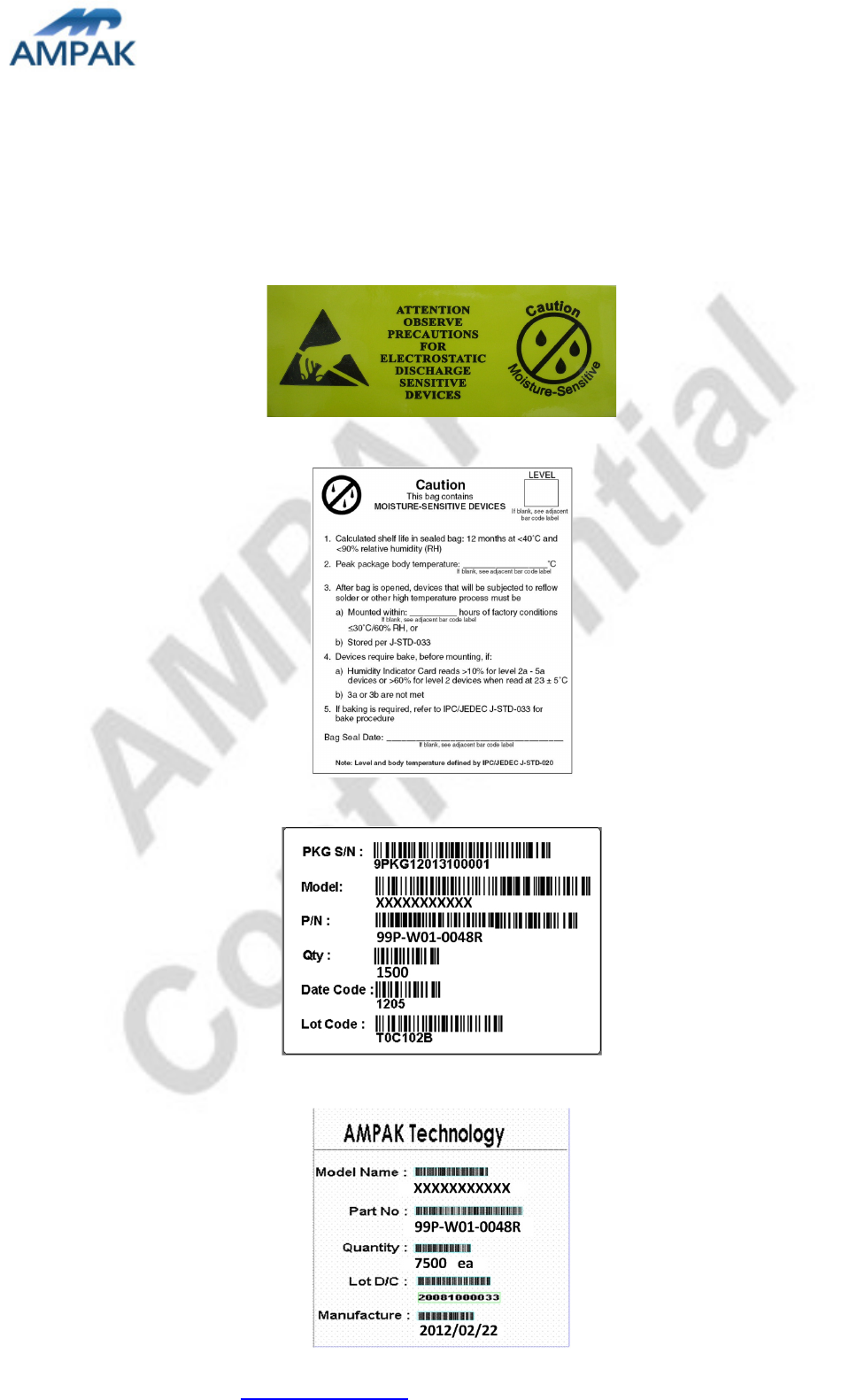
13.1Label
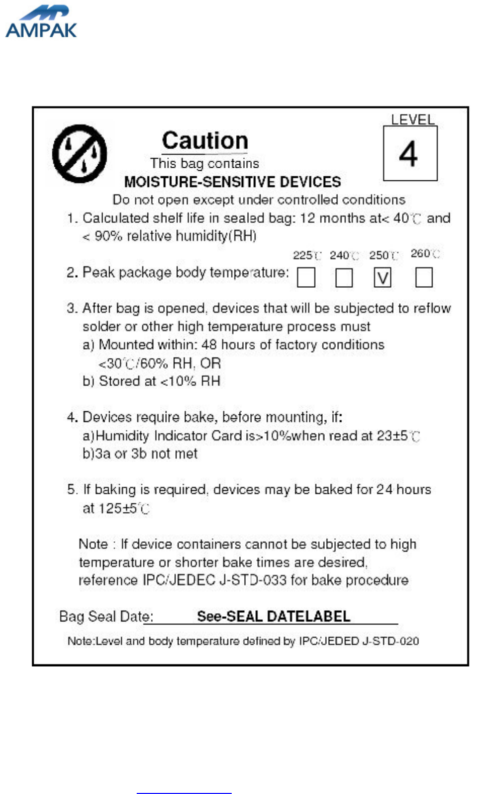
Label A Anti-static and humidity notice
Label B MSL caution / Storage Condition
Label C Inner box label .
Label D Carton box label .

AP6212 Datasheet
AMPAK Technology Inc. www.ampak.com.tw Proprietary & Confidential Information
Doc. NO:
23
13.2 Dimension
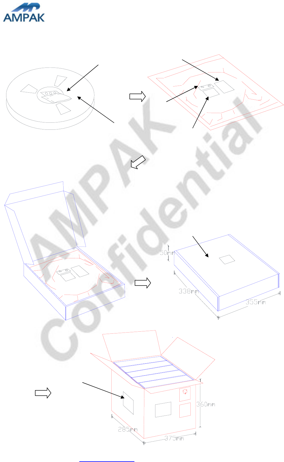
AP6212 Datasheet
AMPAK Technology Inc. www.ampak.com.tw Proprietary & Confidential Information
Doc. NO:
24
A
B
C
Humidity indicator
Desiccant
C
D
AP6212 Datasheet
AMPAK Technology Inc. www.ampak.com.tw Proprietary & Confidential Information
Doc. NO:
25
13.3 MSL Level / Storage Condition
※
※※
※NOTE : Accumulated baking time should not exceed 96hrs

RTL8188EUS
SINGLE-CHIP IEEE 802.11b/g/n 1T1R WLAN
DATASHEET
(CONFIDENTIAL: Development Partners Only)
Rev. 0.2
27 Mar. 2012
Track ID:
Realtek Semiconductor Corp.
No. 2, Innovation Road II, Hsinchu Science Park, Hsinchu 300, Taiwan
Tel.: +886-3-578-0211. Fax: +886-3-577-6047
www.realtek.com
Realtek confidential files
The document authorized to
G.M.I
2012-05-21 17:34:48

RTL8188EUS
Datasheet
COPYRIGHT
©2011 Realtek Semiconductor Corp. All rights reserved. No part of this document may be reproduced,
transmitted, transcribed, stored in a retrieval system, or translated into any language in any form or by any
means without the written permission of Realtek Semiconductor Corp.
DISCLAIMER
Realtek provides this document “as is”, without warranty of any kind. Realtek may make improvements
and/or changes in this document or in the product described in this document at any time. This document
could include technical inaccuracies or typographical errors.
TRADEMARKS
Realtek is a trademark of Realtek Semiconductor Corporation. Other names mentioned in this document are
trademarks/registered trademarks of their respective owners.
USING THIS DOCUMENT
This document is intended for the software engineer’s reference and provides detailed programming
information.
Though every effort has been made to ensure that this document is current and accurate, more information
may have become available subsequent to the production of this guide.
REVISION HISTORY
Revision Release Date Summary
0.2 2012/3/27 Preliminary release
Single-Chip IEEE 802.11b/g/n 1T1R WLAN Controller ii Track ID: JATR-2265-11 Rev. 0.
5
with USB Interface
Realtek confidential files
The document authorized to
G.M.I
2012-05-21 17:34:48

RTL8188EUS
Datasheet
Table of Contents
1.GENERAL DESCRIPTION ...............................................................................................................................................1
2.FEATURES ..........................................................................................................................................................................3
3.APPLICATION DIAGRAM...............................................................................................................................................5
3.1.SINGLE-BAND 11N (1X1) SOLUTION WITH SINGLE ANTENNA .........................................................................................5
3.2.SINGLE-BAND 11N (1X1) SOLUTION WITH DUAL ANTENNA DIVERSITY .........................................................................6
3.3.SINGLE-BAND 11N (1X1) SOLUTION WITH DUAL ANTENNA............................................................................................6
4.PIN ASSIGNMENTS...........................................................................................................................................................7
4.1.PACKAGE IDENTIFICATION..............................................................................................................................................7
5.PIN DESCRIPTIONS..........................................................................................................................................................7
5.1.USB BUS TRANSCEIVER INTERFACE...............................................................................................................................8
5.2.POWER PINS ....................................................................................................................................................................8
5.3.RF INTERFACE ................................................................................................................................................................8
5.4.LED INTERFACE..............................................................................................................................................................9
5.5.CLOCK AND OTHER PINS...............................................................................................................................................10
6.ELECTRICAL AND THERMAL CHARACTERISTICS.............................................................................................11
6.1.TEMPERATURE LIMIT RATINGS .....................................................................................................................................11
6.2.DC CHARACTERISTICS ..................................................................................................................................................11
6.2.1.Power Supply Characteristics.............................................................................................................................11
6.2.2.Digital IO Pin DC Characteristics.......................................................................................................................11
7.INTERFACE TIMING SPECIFICATION .....................................................................................................................13
7.1.USB BUS DURING POWER ON SEQUENCE .....................................................................................................................13
8.MECHANICAL DIMENSIONS.......................................................................................................................................14
8.1.MECHANICAL DIMENSIONS NOTES ...............................................................................................................................14
9.ORDERING INFORMATION.........................................................................................................................................15
Single-Chip IEEE 802.11b/g/n 1T1R WLAN Controller iii Track ID: JATR-2265-11 Rev. 0.
5
with USB Interface
Realtek confidential files
The document authorized to
G.M.I
2012-05-21 17:34:48

RTL8188EUS
Datasheet
List of Tables
TABLE 1. USB BUS TRANSCEIVER INTERFACE...............................................................................................................................8
TABLE 2. POWER PINS ...................................................................................................................................................................8
TABLE 3. RF INTERFACE ...............................................................................................................................................................8
TABLE 4. LED INTERFACE.............................................................................................................................................................9
TABLE 5. CLOCK AND OTHER PINS..............................................................................................................................................10
TABLE 6.TEMPERATURE LIMIT RATINGS .................................................................................................................................11
TABLE 7.DC CHARACTERISTICS ..............................................................................................................................................11
TABLE 8.3.3V GPIO DC CHARACTERISTICS ...........................................................................................................................11
TABLE 9.2.8V GPIO DC CHARACTERISTICS ...........................................................................................................................11
TABLE 10.1.8V GPIO DC CHARACTERISTICS .......................................................................................................................12
TABLE 11.THE TYPICAL TIMING RANGE .................................................................................................................................13
TABLE 12.ORDERING INFORMATION......................................................................................................................................15
List of Figures
FIGURE 1. SINGLE-BAND 11N (1X1) SOLUTION...............................................................................................................................5
FIGURE 2. SINGLE-BAND 11N (1X1) DUAL ANTENNA DIVERSITY SOLUTION....................................................................................6
FIGURE 3. SINGLE-BAND 11N (1X1) DUAL ANTENNA SOLUTION .....................................................................................................6
FIGURE 4. PIN ASSIGNMENTS ..........................................................................................................................................................7
FIGURE 5. RTL8188EUS USB BUS POWER ON SEQUENCE ..........................................................................................................13
Single-Chip IEEE 802.11b/g/n 1T1R WLAN Controller iv Track ID: JATR-2265-11 Rev. 0.
5
with USB Interface
Realtek confidential files
The document authorized to
G.M.I
2012-05-21 17:34:48

RTL8188EUS
Datasheet
1. General Description
The Realtek RTL8188EUS is a highly integrated single-chip 802.11n Wireless LAN (WLAN) network
USB interface (USB 1.0/1.1/2.0 compliant) controller. It combines a WLAN MAC, a 1T1R capable WLAN
baseband, and WLAN RF in a single chip. The RTL8188EUS provides a complete solution for a high
throughput performance integrated wireless LAN device.
The RTL8188EUS WLAN baseband implements Orthogonal Frequency Division Multiplexing (OFDM)
with 1 transmit and 1 receive path and is compatible with the IEEE 802.11n specification. Features include
one spatial stream transmission, short guard interval (GI) of 400ns, spatial spreading, and transmission over
20MHz and 40MHz bandwidth.
For legacy compatibility, Direct Sequence Spread Spectrum (DSSS), Complementary Code Keying (CCK)
and OFDM baseband processing are included to support all IEEE 802.11b and 802.11g data rates.
Differential phase shift keying modulation schemes, DBPSK and DQPSK with data scrambling capability,
are available, and CCK provides support for legacy data rates, with long or short preamble. The high-speed
FFT/IFFT paths, combined with BPSK, QPSK, 16QAM, and 64QAM modulation of the individual
subcarriers and rate compatible punctured convolutional coding with coding rate of 1/2, 2/3, 3/4, and 5/6,
provide higher data rates of 54Mbps and 150Mbps for IEEE 802.11g and 802.11n OFDM respectively.
The RTL8188EUS WLAN Controller builds in an enhanced signal detector, an adaptive frequency domain
equalizer, and a soft-decision Viterbi decoder to alleviate severe multi-path effects and mutual interference
in the reception of multiple streams.
Efficient IQ-imbalance, DC offset, phase noise, frequency offset, and timing offset compensations are
provided for the radio frequency front-end. Selectable digital transmit and receive FIR filters are provided
to meet transmit spectrum mask requirements and to reject adjacent channel interference, respectively.
The RTL8188EUS WLAN Controller supports fast receiver Automatic Gain Control (AGC) with
synchronous and asynchronous control loops among antennas, antenna diversity functions, and adaptive
transmit power control function to obtain the better performance in the analog portions of the transceiver.
The RTL8188EUS WLAN MAC supports 802.11e for multimedia applications, 802.11i for security, and
802.11n for enhanced MAC protocol efficiency. Using packet aggregation techniques such as A-MPDU
Single-Chip IEEE 802.11b/g/n 1T1R WLAN Controller 1 Track ID: JATR-2265-11 Rev. 0.1
with USB Interface
Realtek confidential files
The document authorized to
G.M.I
2012-05-21 17:34:48

RTL8188EUS
Datasheet
with BA and A-MSDU, protocol efficiency is significantly improved. Power saving mechanisms such as
Legacy Power Save, and U-APSD, reduce the power wasted during idle time, and compensates for the extra
power required to transmit OFDM. The RTL8188EUS provides simple legacy and 20MHz/40MHz
co-existence mechanisms to ensure backward and network compatibility.
Single-Chip IEEE 802.11b/g/n 1T1R WLAN Controller 2 Track ID: JATR-2265-11 Rev. 0.1
with USB Interface
Realtek confidential files
The document authorized to
G.M.I
2012-05-21 17:34:48

RTL8188EUS
Datasheet
2. Features
General
46-pin QFN
CMOS MAC, Baseband PHY, and RF in a
single chip for IEEE 802.11b/g/n
compatible WLAN
Complete 802.11n solution for 2.4GHz
band
72.2Mbps receive PHY rate and 72.2Mbps
transmit PHY rate using 20MHz bandwidth
150Mbps receive PHY rate and 150Mbps
transmit PHY rate using 40MHz bandwidth
Compatible with 802.11n specification
Backward compatible with 802.11b/g
devices while operating in 802.11n mode
Interface
Complies with USB 1.0/1.1/2.0 for WLAN
Standards Supported
IEEE 802.11b/g/n compatible WLAN
IEEE 802.11e QoS Enhancement (WMM)
802.11i (WPA, WPA2). Open, shared key,
and pair-wise key authentication services
WLAN MAC Features
Frame aggregation for increased MAC
efficiency (A-MSDU, A-MPDU)
Low latency immediate High-Throughput
Block Acknowledgement (HT-BA)
PHY-level spoofing to enhance legacy
compatibility
Power saving mechanism
Channel management and co-existence
Transmit Opportunity (TXOP) Short
Inter-Frame Space (SIFS) bursting for
higher multimedia bandwidth
WLAN PHY Features
IEEE 802.11n OFDM
One Transmit and one Receive path (1T1R)
20MHz and 40MHz bandwidth
transmission
Short Guard Interval (400ns)
DSSS with DBPSK and DQPSK, CCK
modulation with long and short preamble
OFDM with BPSK, QPSK, 16QAM, and
64QAM modulation.
Convolutional Coding Rate: 1/2, 2/3, 3/4,
and 5/6
Maximum data rate 54Mbps in 802.11g and
150Mbps in 802.11n
Hardware antenna diversity in per packet
base
Selectable receiver FIR filters
Programmable scaling in transmitter and
receiver to trade quantization noise against
increased probability of clipping
Fast receiver Automatic Gain Control
(AGC)
On-chip ADC and DAC
Single-Chip IEEE 802.11b/g/n 1T1R WLAN Controller 3 Track ID: JATR-2265-11 Rev. 0.1
with USB Interface
Realtek confidential files
The document authorized to
G.M.I
2012-05-21 17:34:48

RTL8188EUS
Datasheet
Peripheral Interfaces
General Purpose Input/Output (8 pins)
Three configurable LED pins
Single-Chip IEEE 802.11b/g/n 1T1R WLAN Controller 4 Track ID: JATR-2265-11 Rev. 0.1
with USB Interface
Realtek confidential files
The document authorized to
G.M.I
2012-05-21 17:34:48
RTL8188EUS
Datasheet
3. Application Diagram
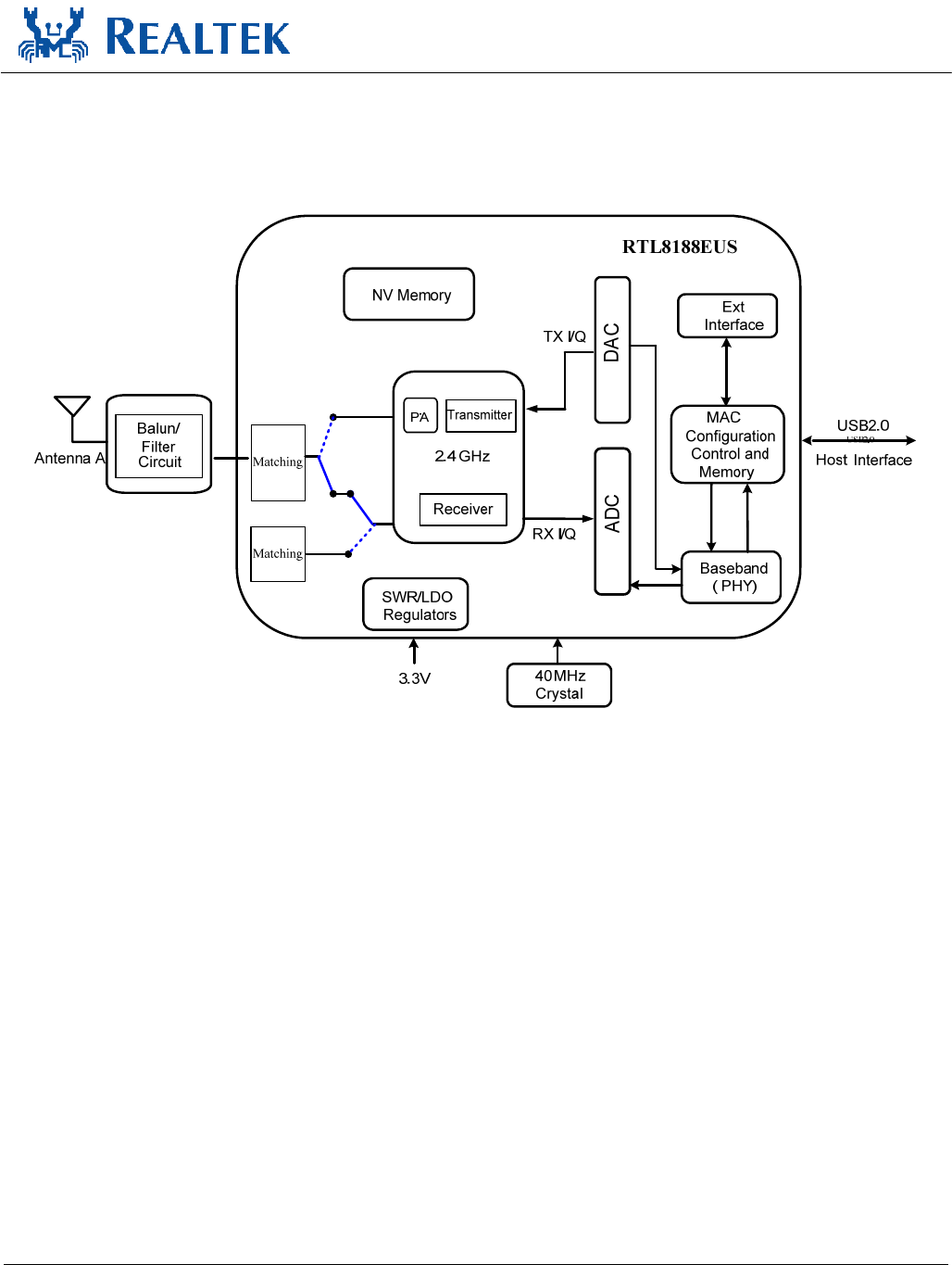
3.1.
Single-Band 11n (1x1) Solution with Single Antenna
Figure 1. Single-Band 11n (1x1) Solution
Single-Chip IEEE 802.11b/g/n 1T1R WLAN Controller 5 Track ID: JATR-2265-11 Rev. 0.1
with USB Interface
Realtek confidential files
The document authorized to
G.M.I
2012-05-21 17:34:48
RTL8188EUS
Datasheet
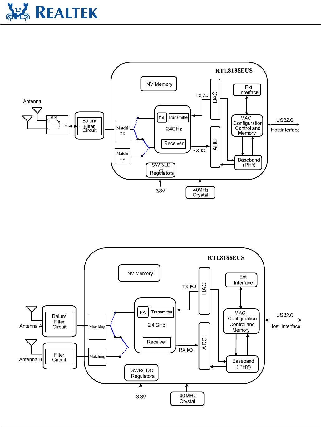
3.2.
Single-Band 11n (1x1) Solution with Transmit & Receive
Diversity
Figure 2. Single-Band 11n (1x1) Transmit & Receive Diversity solution
3.3.
Single-Band 11n (1x1) Solution with Transmit & Receive
Diversity
Figure 3. Single-Band 11n (1x1) Transmit & Receive Diversity sSolution
Single-Chip IEEE 802.11b/g/n 1T1R WLAN Controller 6 Track ID: JATR-2265-11 Rev. 0.1
with USB Interface
Realtek confidential files
The document authorized to
G.M.I
2012-05-21 17:34:48
RTL8188EUS
Datasheet
4. Pin Assignments
23
21
20
19
18
17
16
15
14
13
12
11
10
22
33
34
35
36
37
38
39
40
41
42
43
45
46
44
NC
XI
ANT_SEL_N/LED1
NC
VD12A
XO
GPIO[8]/CK_OUT
NC
GND
LX_SPS
VD33A
ANT_SEL_2
VD12D
GPIO[3]/BT_PRI
SPS/LD0_SEL/GPIO[1]
TRSWP
GPIO[0]/WLAN_ACT
GPIO[2]/BT_STATE
VD33D
VD33D
VD12D
NC
GPIO[7]
GPIO[4]
TRSWN
VD33D GPIO[5]/LED2
ANT_SEL_P/LED0
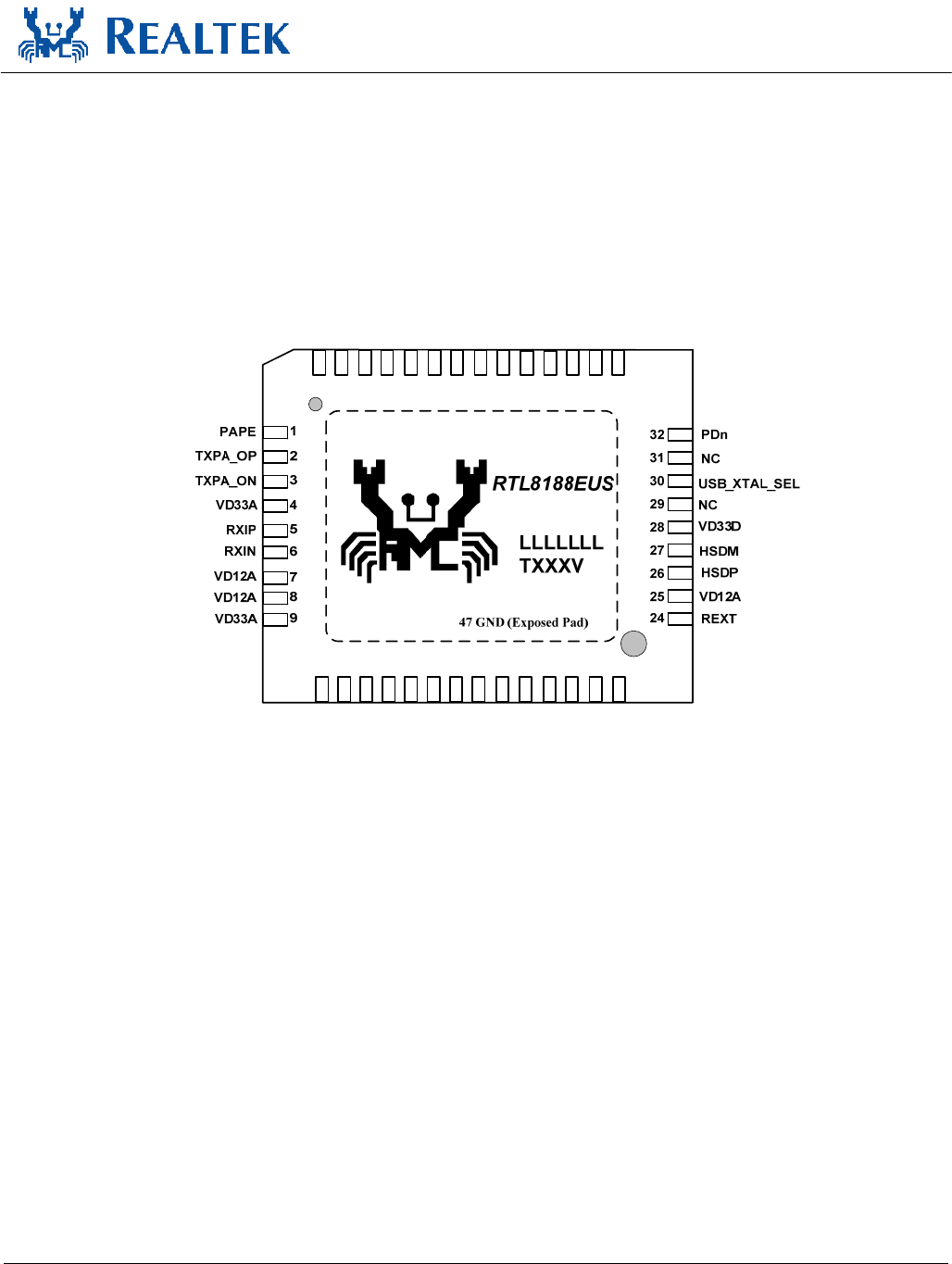
Figure 4. Pin Assignments
4.1.
Package Identification
‘Green’ package is indicated by a ‘G’ in the location marked ‘T’ in Figure 4.
5. Pin Descriptions
The following signal type codes are used in the tables:
I: Input O: Output
T/S: Tri-State bi-directional input/output pin S/T/S: Sustained Tri-State
Single-Chip IEEE 802.11b/g/n 1T1R WLAN Controller 7 Track ID: JATR-2265-11 Rev. 0.1
with USB Interface
Realtek confidential files
The document authorized to
G.M.I
2012-05-21 17:34:48

RTL8188EUS
Datasheet
O/D: Open Drain P: Power pin
5.1.
USB Bus Transceiver Interface
Table 1. USB bus Transceiver Interface
Symbol Type Pin No Description
HSDM/HSDP I 27/26 USB Receive Differential Pair
5.2.
Power Pins
Table 2. Power Pins
Symbol Type Pin No Description
LX_SPS P 22 Switching Regulator Output
VD33A P 4,9,12, VDD 3.3V for Analog
VD33D P 23,28,40,41 VDD 3.3V for Digital
VD12A P 7,8,13,25 Analog 1.2V Regulator Output
VD12D P 17,42 Digital 1.2V Regulator Output
GND P 21,47 Ground
5.3.
RF Interface
Table 3. RF Interface
Symbol Type Pin No Description
TRSWN O 45 Transmit/Receive
Shared with LED2, can be selected by control register
PAPE O 1 2.4GHz Transmit Power Amplifier Power Enable 0
TRSWP O 46 Transmit/Receive
TXPA_OP O 2 RF TX Negative Signal
TXPA_ON O 3 RF TX Positive Signal
RX_IP I 5 RF RX Positive Signal
RX_IN I 6 RF RX Negative Signal
ANT_SEL_P O 44 Antenna Control Positive Signal
Shared with LED0, can be selected by control register
ANT_SEL_N O 15 Antenna Control Negative Signal
Shared with LED1, can be selected by control register
ANT_SEL_2 O 16 Antenna Control Extend Signal
Single-Chip IEEE 802.11b/g/n 1T1R WLAN Controller 8 Track ID: JATR-2265-11 Rev. 0.1
with USB Interface
Realtek confidential files
The document authorized to
G.M.I
2012-05-21 17:34:48

RTL8188EUS
Datasheet
5.4.
LED Interface
Table 4. LED Interface
Symbol Type Pin No Description
LED0 O 44 LED Pins (Active Low)
Shared with ANT_SEL_P, can be selected by control register
LED1 O 15 LED Pins (Active Low)
Shared with ANT_SEL_N, can be selected by control register
LED2 O 33 LED Pins (Active Low)
Shared with GPIO5, can be selected by control register
Single-Chip IEEE 802.11b/g/n 1T1R WLAN Controller 9 Track ID: JATR-2265-11 Rev. 0.1
with USB Interface
Realtek confidential files
The document authorized to
G.M.I
2012-05-21 17:34:48

RTL8188EUS
Datasheet
5.5.
Clock and Other Pins
Table 5. Clock and Other Pins
Symbol Type Pin No Description
XI I 11 25/40MHz OSC Input
Input of 25/40MHz Crystal clock reference
XO O 10 Output of 25/40MHz Crystal Clock Reference
PDn I 32 This Pin can Externally Shutdown RTL8188CE without Extra Power Switch
REXT O 24 Band gap. It needs to link 24k resister pull down.
USB_XTAL_SEL I 30 Trap Function: Decide to use the 25/40Mhz crystal by this pin power on
latch low or high.
USB_XTAL_SEL = 1, XTAL frequency is 40MHz
USB_XTAL_SEL = 0, XTAL frequency is 25MHz
GPIO0/WLAN_ACT IO 36 General Purpose Input/Output Pin or Bluetooth Coexistence WLAN_ACT
Pin
The WLAN_ACT signal indicates when WLAN is either transmitting or
receiving in the 2.4GHz ISM band.
GPIO1/ (SPS/LDO_SEL
mode) IO 39 Trap Function: Decide to use the SWR or LDO for 3.3V -> 1.2V by this pin
power on latch low or high.
LDO_SPS_SEL = 0, use SWR
LDO_SPS_SEL = 1, use LDO
General Purpose Input/Output Pin or Bluetooth Coexistence WLAN_RX
Pin.
GPIO2/BT_STATE IO 37 General Purpose Input/Output Pin or Bluetooth Coexistence BT_STAT Pin
The BTSTAT signal indicates when normal Bluetooth packets are being
transmitted or received.
GPIO3/BT_PRI IO 38 General Purpose Input/Output Pin or Bluetooth Coexistence BT_PRI Pin
The BTPRI signal indicates when a high priority Bluetooth packet is being
transmitted or received.
GPIO4 IO 35 General Purpose Input/Output Pin
GPIO5/LED2 IO 33 General Purpose Input/Output Pin
Shared with LED2, can be selected by control register
GPIO7 IO 34 This pin can also support WLAN Radio off function with host interface
remaining connected.
GPIO8/CK_OUT IO 14 General Purpose Input/Output Pin
Buffered 25/40M clock outputs for other peripheral IC
NC NA 18,19,20
,29,31,
43
No connect. Let it open.
Single-Chip IEEE 802.11b/g/n 1T1R WLAN Controller 10 Track ID: JATR-2265-11 Rev. 0.1
with USB Interface
Realtek confidential files
The document authorized to
G.M.I
2012-05-21 17:34:48

RTL8188EUS
Datasheet
6. Electrical and Thermal Characteristics
6.1.
Temperature Limit Ratings
Table 6. Temperature Limit Ratings
Parameter Minimum Maximum Units
Storage Temperature -55 +125 °C
Ambient Operating Temperature 0 70 °C
Junction Temperature 0 125 °C
6.2.
DC Characteristics
6.2.1. Power Supply Characteristics
Table 7. DC Characteristics
Symbol Parameter Minimum Typical Maximum Units
VD33A, VD33D 3.3V I/O Supply Voltage 3.0 3.3 3.6 V
VD12A, VD12D 1.2V Core Supply Voltage 1.10 1.2 1.32 V
VD15A, VD15D 1.5V Supply Voltage 1.425 1.5 1.575 V
IDD33 3.3V Rating Current - - 600 mA
6.2.2. Digital IO Pin DC Characteristics
Table 8. 3.3V GPIO DC Characteristics
Symbol Parameter Minimum Normal Maximum Units
VIH Input high voltage 2.0 3.3 3.6 V
VIL Input low voltage -- 0 0.9 V
VOH Output high voltage 2.97 -- 3.3 V
VOL Output low voltage 0 -- 0.33 V
Table 9. 2.8V GPIO DC Characteristics
Symbol Parameter Minimum Normal Maximum Units
VIH Input high voltage 1.8 2.8 3.1 V
VIL Input low voltage -- 0 0.8 V
VOH Output high voltage 2.5 -- 3.1 V
VOL Output low voltage 0 -- 0.28 V
Single-Chip IEEE 802.11b/g/n 1T1R WLAN Controller 11 Track ID: JATR-2265-11 Rev. 0.1
with USB Interface
Realtek confidential files
The document authorized to
G.M.I
2012-05-21 17:34:48

RTL8188EUS
Datasheet
Table 10. 1.8V GPIO DC Characteristics
Symbol Parameter Minimum Normal Maximum Units
VIH Input high voltage 1.7 1.8 2.0 V
VIL Input low voltage -- 0 0.8 V
VOH Output high voltage 1.62 -- 1.8 V
VOL Output low voltage 0 -- 0.18 V
Single-Chip IEEE 802.11b/g/n 1T1R WLAN Controller 12 Track ID: JATR-2265-11 Rev. 0.1
with USB Interface
Realtek confidential files
The document authorized to
G.M.I
2012-05-21 17:34:48
RTL8188EUS
Datasheet
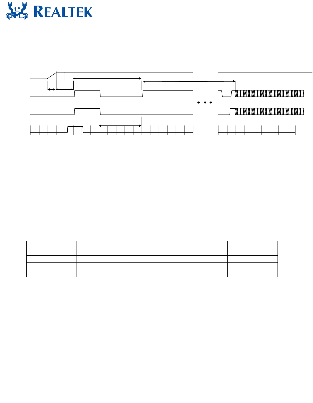
7. Interface Timing Specification
7.1.
USB Bus during Power On Sequence
3.3V
T
on
T
POR
T
attach
T
k-state
Card Detection
D+
D-
SE0 Reset
POR
Figure 5. RTL8188EUS USB Bus Power On Sequence
Ton: The main power ramp up duration
Tpor: The power on reset releases and power management unit executes power on tasks
Tattach: USB attach state
Tk-state: the duration from resister attached to USB host starting card detection procedure
The power on flow description:
After main 3.3V ramp up, the internal power on reset is released by power ready detection circuit and the power management
unit will be enabled. The power management unit enables the internal regulator and clock circuits.
The power management unit also enables the USB circuits.
USB analog circuits attach resisters to indicate the insertion of the USB device
Table 11. The typical timing range
Unit Min Typical Max
Ton ms -- 1.5 5
Tpor ms -- 2 10
Tattach ms 2 7 15
Tk-state ms 50 250 --
Single-Chip IEEE 802.11b/g/n 1T1R WLAN Controller 13 Track ID: JATR-2265-11 Rev. 0.1
with USB Interface
Realtek confidential files
The document authorized to
G.M.I
2012-05-21 17:34:48
RTL8188EUS
Datasheet
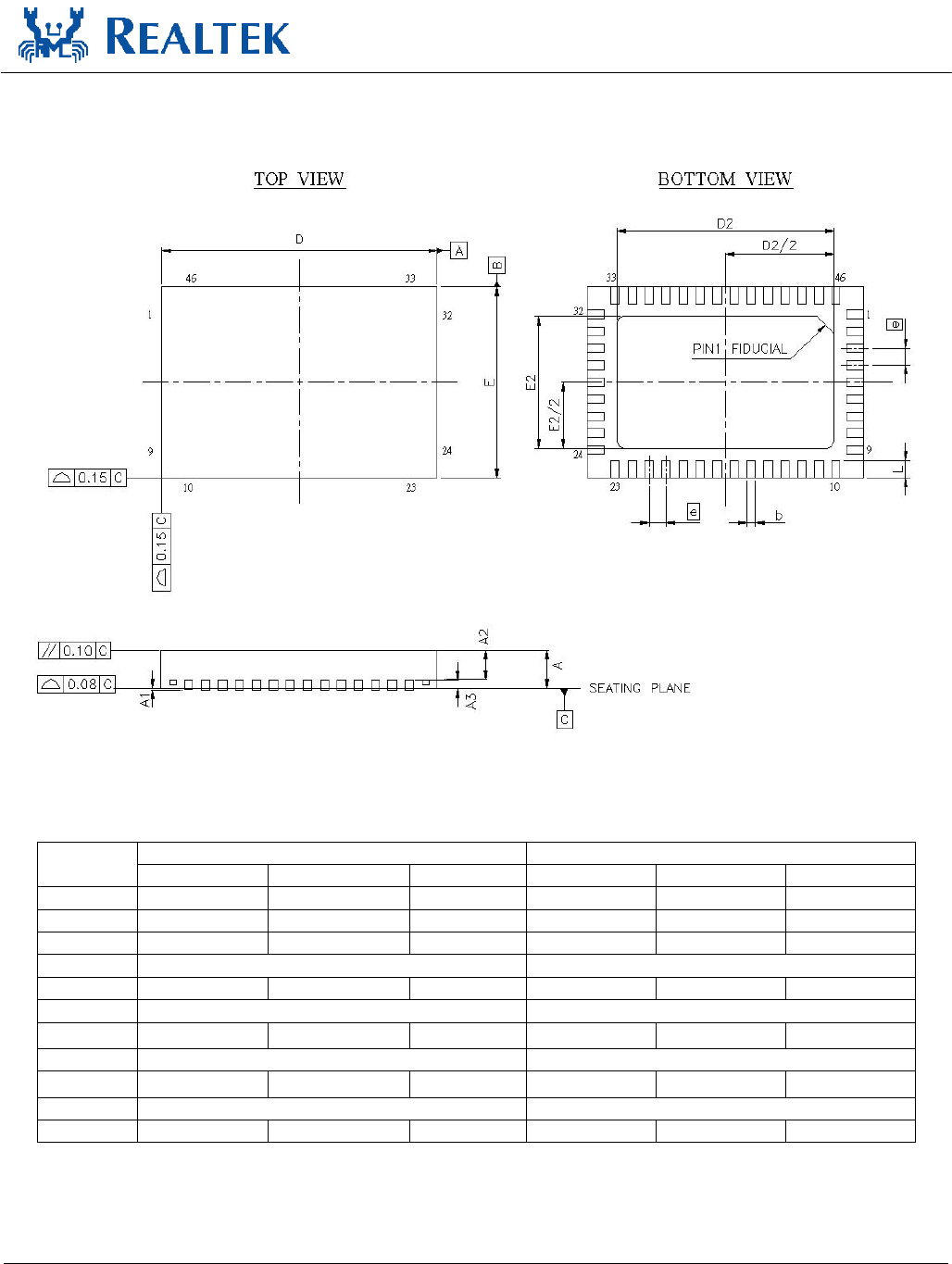
8. Mechanical Dimensions
8.1.
Mechanical Dimensions Notes
Dimension in mm Dimension in inch
Symbol Min Nom Max Min Nom Max
A 0.75 0.85 1.00 0.030 0.034 0.039
A10.00 0.035 0.05 0.000 0.001 0.002
A20.55 0.65 0.80 0.022 0.026 0.032
A30.20 REF 0.008 REF
b 0.15 0.20 0.25 0.006 0.008 0.010
D 6.50BSC 0.256BSC
D2 4.85 5.1 5.35 0.191 0.201 0.211
E 4.5BSC 0.177BSC
E2 2.25 2.5 2.75 0.088 0.098 0.108
e 0.40BSC 0.016BSC
L 0.30 0.40 0.50 0.012 0.016 0.020
Notes:
1. CONTROLLING DIMENSION:MILLIMETER(mm).
2. REFERENCE DOCUMENTL:JEDEC MO-220.
Single-Chip IEEE 802.11b/g/n 1T1R WLAN Controller 14 Track ID: JATR-2265-11 Rev. 0.1
with USB Interface
Realtek confidential files
The document authorized to
G.M.I
2012-05-21 17:34:48

RTL8188EUS
Datasheet
9. Ordering Information
Table 12. Ordering Information
Part Number Package Status
RTL8188EUS-CG QFN-46, ‘Green’ Package Engineering Samples
Note: See page 7 for package identification.
Realtek Semiconductor Corp.
Headquarters
No. 2, Innovation Road II, Hsinchu Science Park,
Hsinchu 300, Taiwan, R.O.C.
Tel: 886-3-5780211 Fax: 886-3-5776047
www.realtek.com
Single-Chip IEEE 802.11b/g/n 1T1R WLAN Controller 15 Track ID: JATR-2265-11 Rev. 0.1
with USB Interface
Realtek confidential files
The document authorized to
G.M.I
2012-05-21 17:34:48