Xiamen Four Faith Communication Technology F2414 WCDMA/HSDPA/HSUPA IP Modem F2414 User Manual
Xiamen Four-Faith Communication Technology Co., Ltd. WCDMA/HSDPA/HSUPA IP Modem F2414
UserManual.wiki
>
Xiamen Four Faith Communication Technology
>
F2414 User Manual
user manual
Navigation menu
Upload a User Manual
Namespaces
Wiki Guide
HTML
PDF
Info
Views
User Manual
Discussion / Help
Navigation

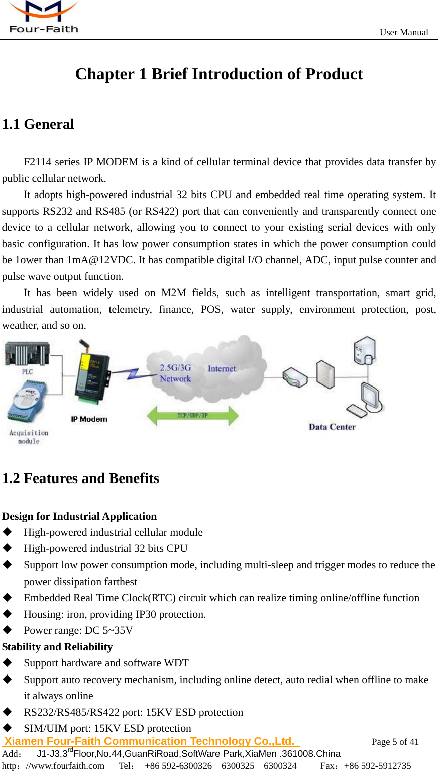
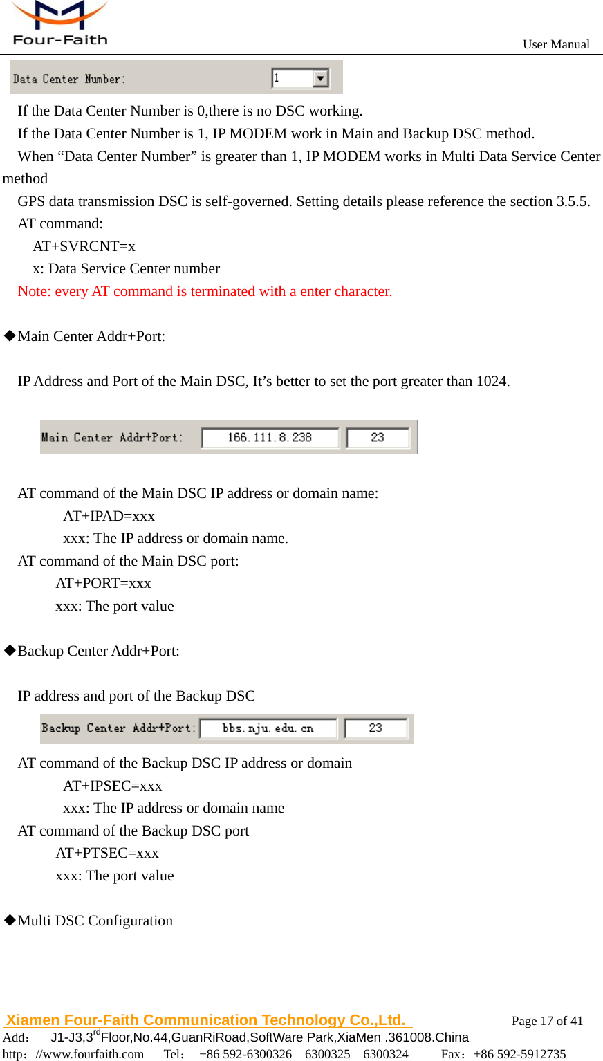
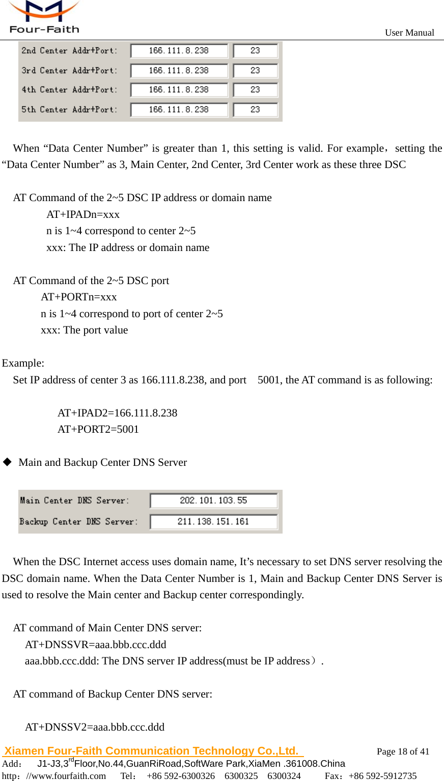
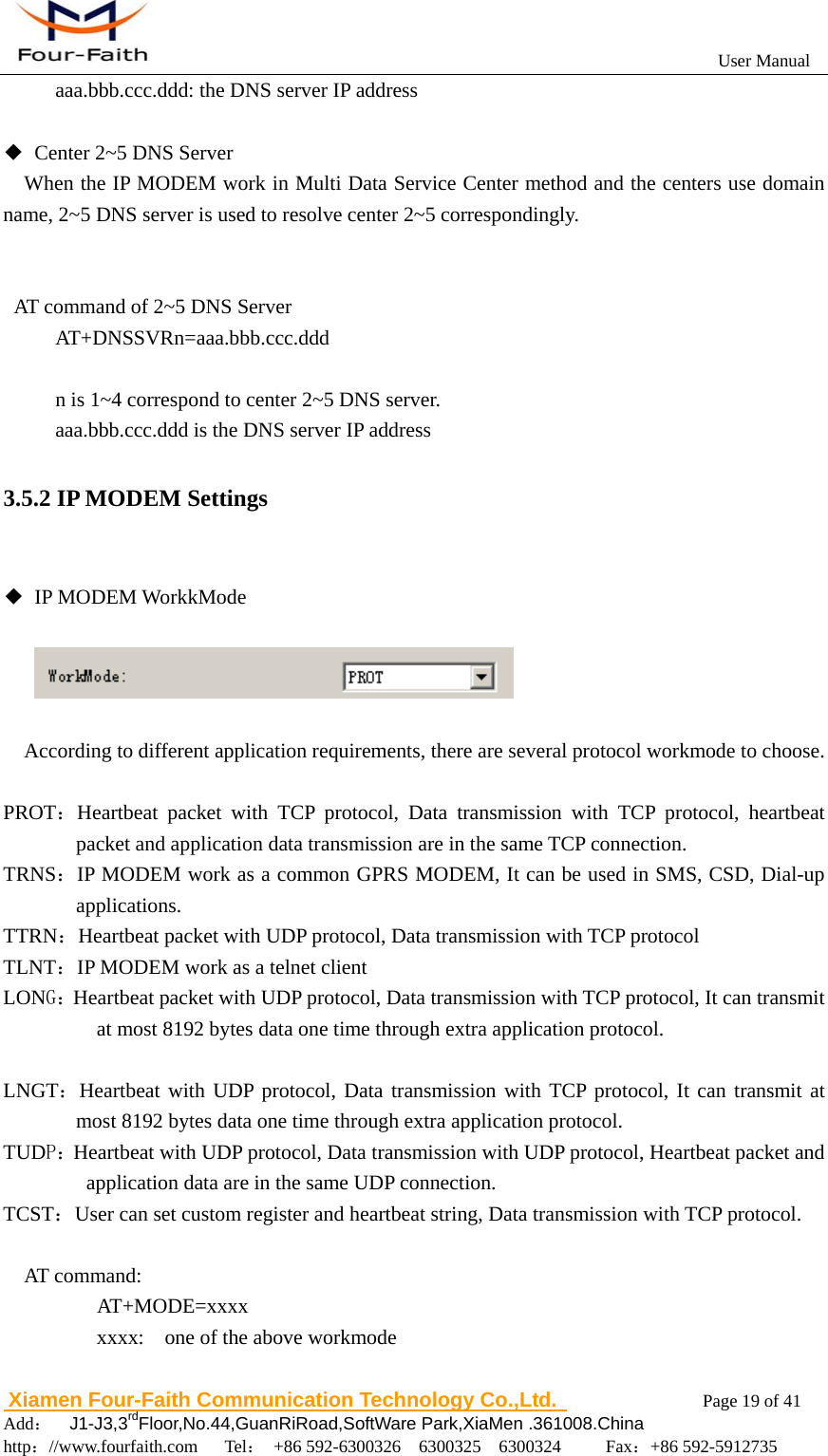
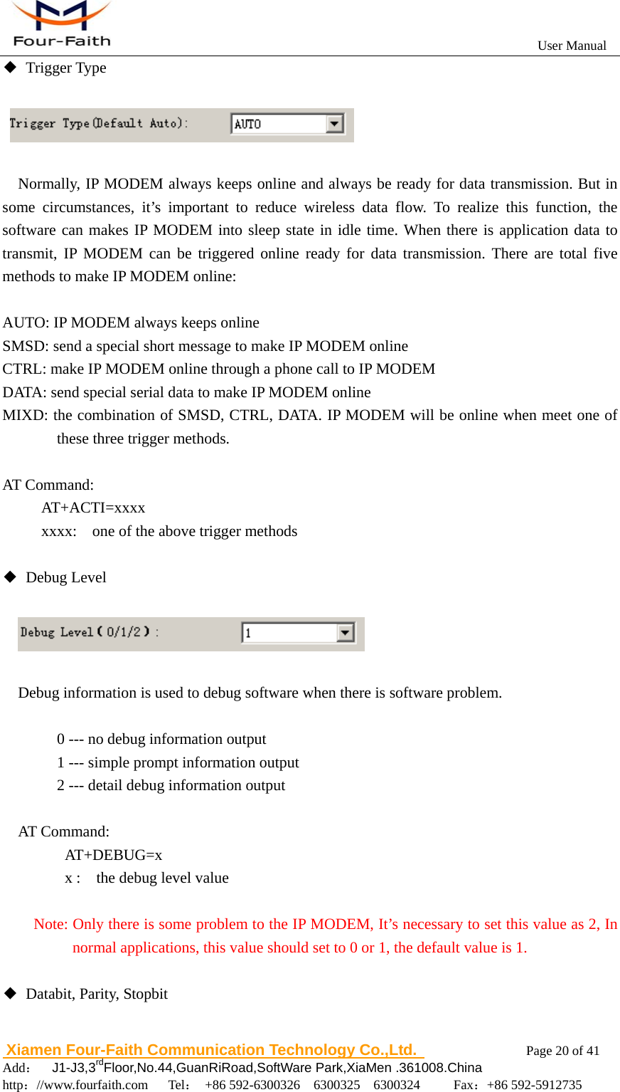
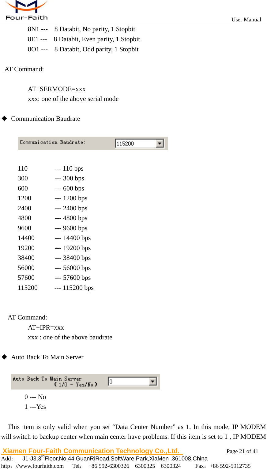
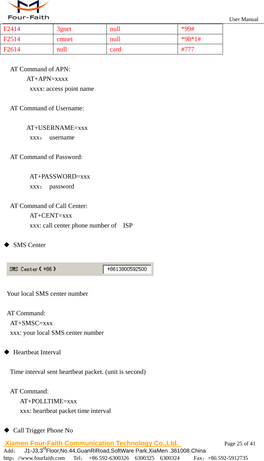
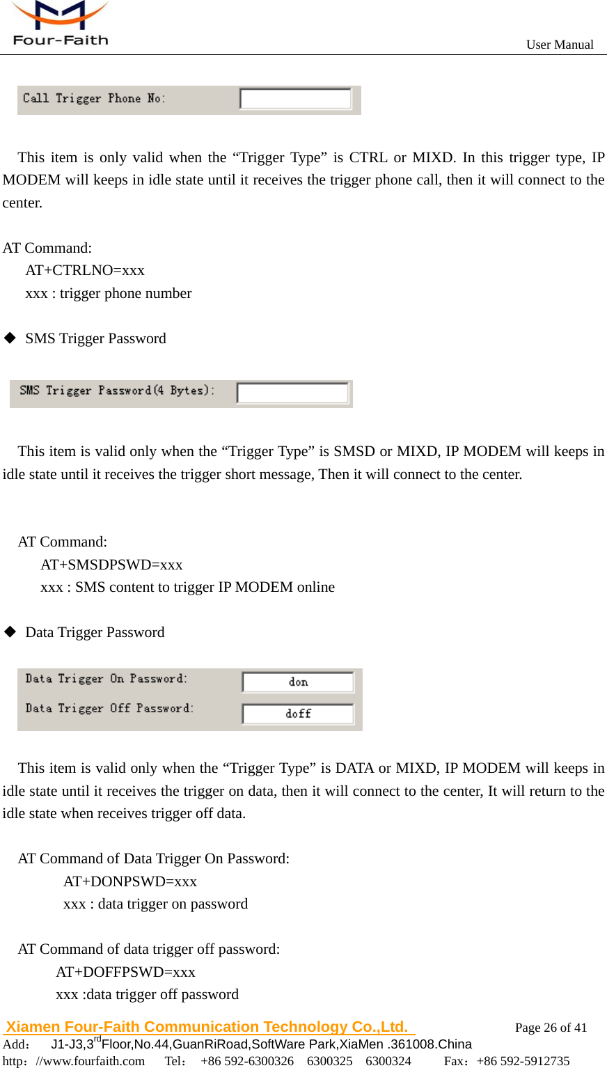
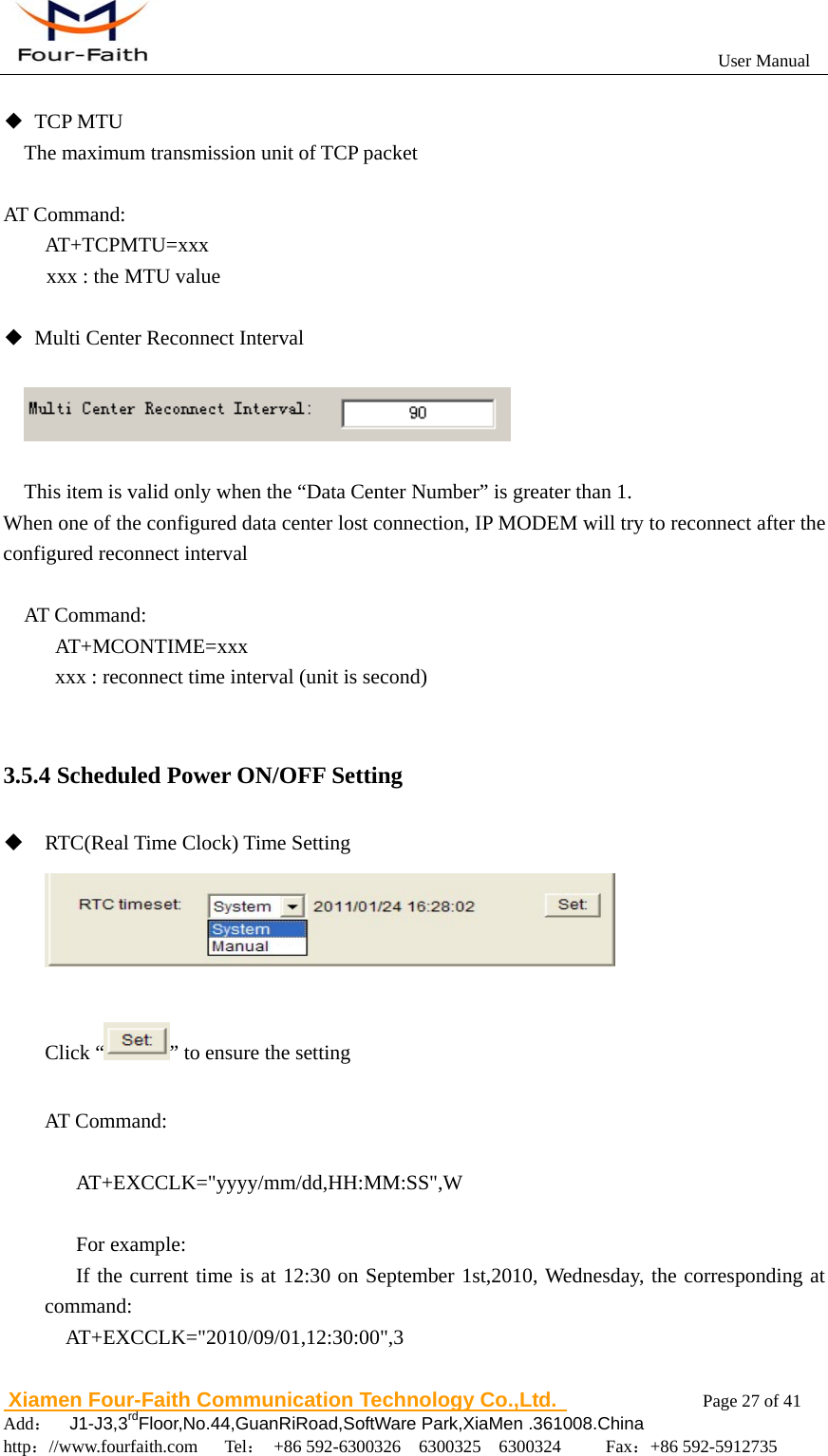
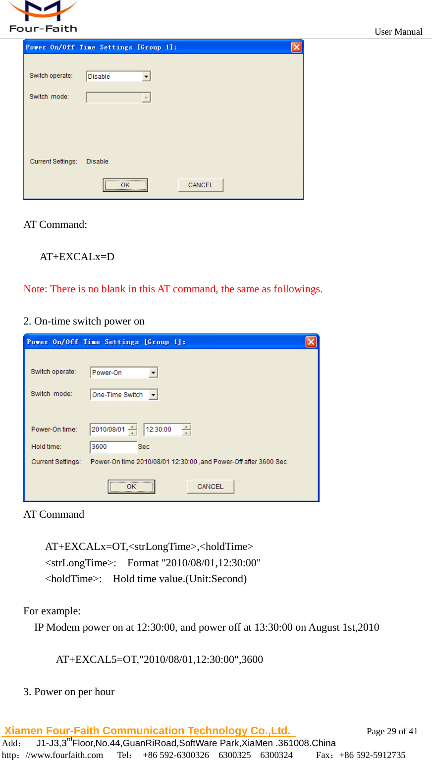
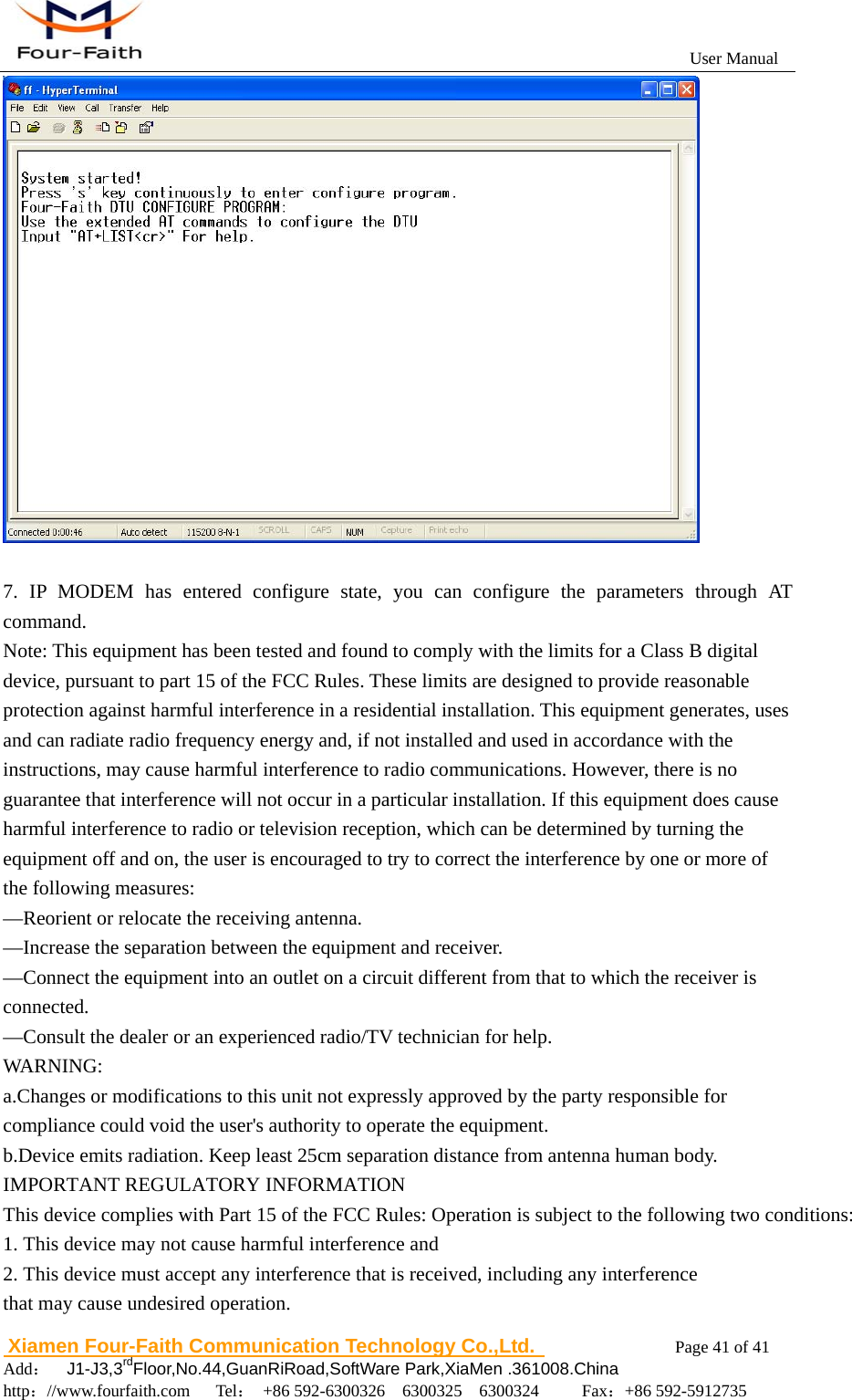
![User Manual Xiamen Four-Faith Communication Technology Co.,Ltd. Page 28 of 41 Add: J1-J3,3rdFloor,No.44,GuanRiRoad,SoftWare Park,XiaMen .361008.China http://www.fourfaith.com Tel: +86 592-6300326 6300325 6300324 Fax:+86 592-5912735 Power On/Off Setting Press “Set” you will see the follow window, you can do the setting. AT Command: AT+EXCALx=<options>[, <value1>[,<value2>[,<value3>]]] Options: D -- Disabled. Scheduled Power On/Off function is disabled (Default). O – On. Set the IP Modem power on time. S – Shut Down. Set the IP Modem power off time. Setting type, [IP] use for power on, C use for power off T -- Time. Set the action time point. H -- per Hour. Set a time point of every hour D -- per Day. Set a time point of every day W -- per Week. Set a time point of every week M -- per Month. Set a time point of every month I -- Interval. Set the time interval. P -- Power always on. C -- Count down. Set the count down length. 1. Disable](https://usermanual.wiki/Xiamen-Four-Faith-Communication-Technology/F2414/User-Guide-1702274-Page-28.png)