Xiamen Four Faith Communication Technology F8L10GW F8L10GW LoRa Gateway User Manual
Xiamen Four-Faith Communication Technology Co., Ltd. F8L10GW LoRa Gateway Users Manual
Contents
- 1. user manual
- 2. User Manual
user manual

F8L10GW LoRa Gateway
User Manual
FCC ID:2ALUW-F8L10GW
F8L10GW LoRa Gateway
Page 2 of 37
Add:11th Floor, A-06 Area, No.370, Chengyi Street, Jimei, Xiamen, Fujian, China.
http://www.four-faith.com Tel:+86-592-6307217 Fax: +86-592-5912735
Files Revised Record
Date
Version
Remark
Author
2018.07.19
V1.0.0
Initial version
Cheney/Carolin
2018.10.11
V1.0.1
Add 1-3 system block diagram;
Modify document format;
Document style adjust;
Font size adjustment.
Jim

F8L10GW LoRa Gateway
Page 3 of 37
Add:11th Floor, A-06 Area, No.370, Chengyi Street, Jimei, Xiamen, Fujian, China.
http://www.four-faith.com Tel:+86-592-6307217 Fax: +86-592-5912735
Copyright Notice
All contents in the files are protected by copyright law, and all copyrights are reserved by
Xiamen Four-Faith Communication Technology Co., Ltd. Without written permission, all
commercial use of the files from Four-Faith are forbidden, such as copy, distribute,
reproduce the files, etc., but non-commercial purpose, downloaded or printed by individual
(all files shall be not revised, and the copyright and other proprietorship notice shall be
reserved) are welcome.
Trademark Notice
Four-Faith、四信、 、 、 are all registered trademarks of
Xiamen Four-Faith Communication Technology Co., Ltd., illegal use of the name of
Four-Faith, trademarks and other marks of Four-Faith is forbidden, unless written
permission is authorized in advance.
F8L10GW LoRa Gateway
Page 4 of 37
Add:11th Floor, A-06 Area, No.370, Chengyi Street, Jimei, Xiamen, Fujian, China.
http://www.four-faith.com Tel:+86-592-6307217 Fax: +86-592-5912735
Pole-mounted Installation
Wall-mounted Installation
Note: Accessories are subject to the purchased model.

F8L10GW LoRa Gateway
Page 5 of 37
Add:11th Floor, A-06 Area, No.370, Chengyi Street, Jimei, Xiamen, Fujian, China.
http://www.four-faith.com Tel:+86-592-6307217 Fax: +86-592-5912735
C
Co
on
nt
te
en
nt
ts
s
Chapter 1 Brief Introduction .......................................................................................................... 6
1.1 General ................................................................................................................................ 6
1.2 Features and Benefits .......................................................................................................... 7
1.3 Working Principle ............................................................................................................... 7
1.4 Specifications ...................................................................................................................... 8
Chapter 2 Installation Instruction ............................................................................................... 11
2.1 General .............................................................................................................................. 11
2.2 Packing List ...................................................................................................................... 11
2.2.1. Wall-mounted Packing List............................................................................... 11
2.2.2. Pole-mounted Packing List .............................................................................. 11
2.3 Installation......................................................................................................................... 12
2.3.1 SIM/UIM Installation ........................................................................................... 12
2.3.2 Wall-mounted Installation .................................................................................. 13
2.3.3 Pole-mounted Installation .................................................................................. 16
2.3.4 Antenna Installation ............................................................................................ 17
2.4 Indicator light description ................................................................................................. 18
Chapter 3 Configuration .............................................................................................................. 20
3.1 Configuration Connection ................................................................................................. 20
3.2 Access to Configuration Web Page ................................................................................... 20
3.2.1 IP Address Setting .............................................................................................. 20
3.2.2 Login configuration web page ........................................................................... 21
3.3 Management & Configuration .......................................................................................... 23
3.3.1 Connection Setting ............................................................................................. 23
3.3.2 WiFi ....................................................................................................................... 25
3.3.2.1 Basic Configuration .................................................................................... 26
3.3.3 LoRaWAN Application ........................................................................................ 27
3.3.4 ADMINISTER ...................................................................................................... 28
3.3.4.1 ADMINISTER ............................................................................................ 28
3.3.4.2 The factory default ...................................................................................... 31
3.3.4.3 Firmware Upgrade ...................................................................................... 32
3.3.4.4 Backup ........................................................................................................ 32
3.3.5 State...................................................................................................................... 34
3.3.5.1 F8L10GW ................................................................................................... 34
Appendix ........................................................................................................................................ 36
F8L10GW LoRa Gateway
Page 6 of 37
Add:11th Floor, A-06 Area, No.370, Chengyi Street, Jimei, Xiamen, Fujian, China.
http://www.four-faith.com Tel:+86-592-6307217 Fax: +86-592-5912735
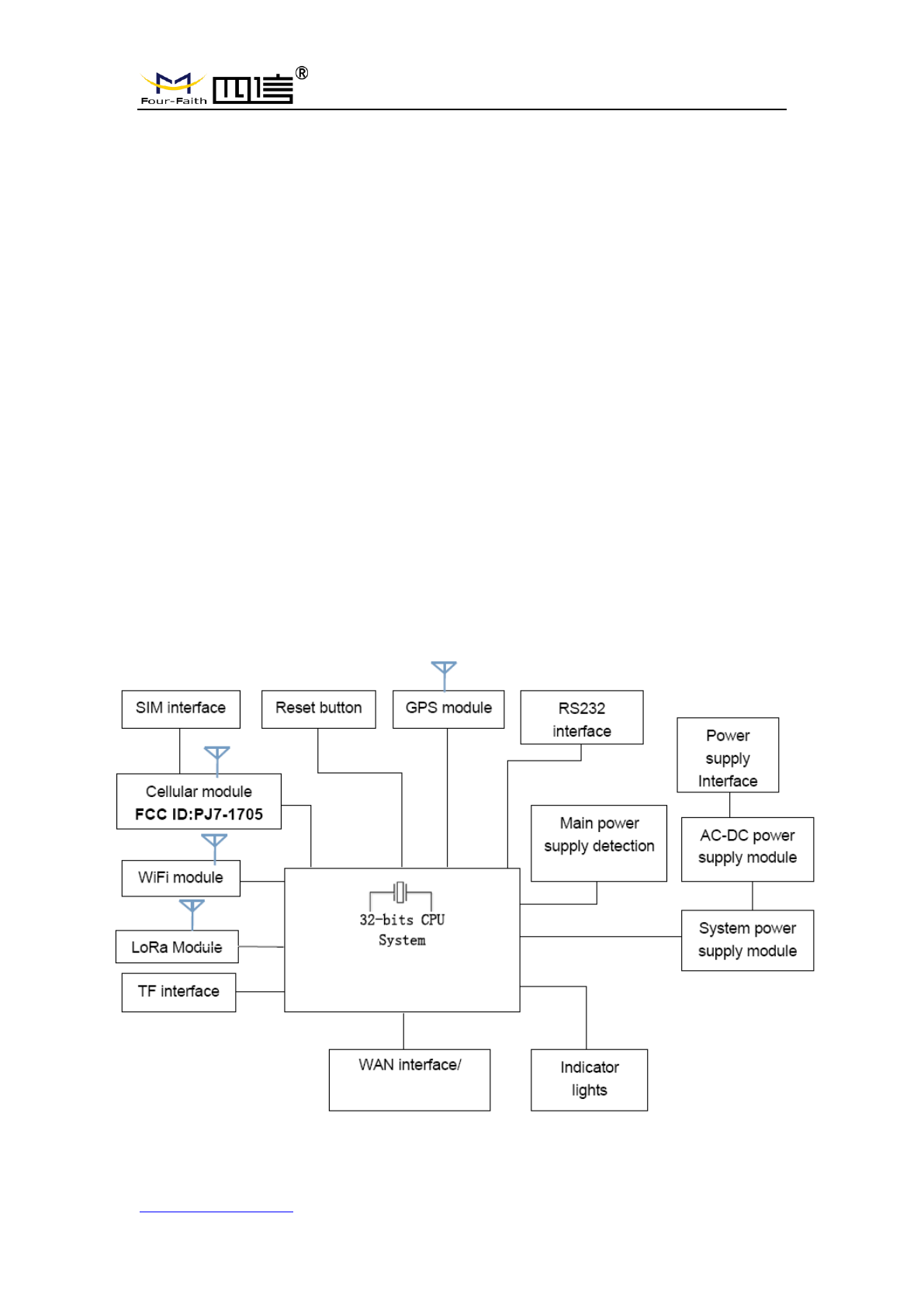
Chapter 1 Brief Introduction
1.1 General
F8L10GW LoRa Gateway is a wireless communication base station based on
LoRaWAN protocol. It connects to LoRaWAN terminals of various applications and
transmits terminal data to the cloud through 3G/4G or wired Ethernet. Support WiFi
wireless configuration management and online upgrade, GPS positioning, AC power
supply.
F8L10GW is complied with standard LoRaWAN protocol, it’s compatible with
LoRaWAN devices and NS. The product has been widely used in M2M industry, smart
grid, smart transportation, industrial automation, intelligent buildings, fire control, public
security, environmental protection, meteorology, digital medical treatment, telemetry,
military, space exploration, agriculture, forestry, water, mining, petrochemical and other
fields.
F8L10GW LoRa Gateway
Page 7 of 37
Add:11th Floor, A-06 Area, No.370, Chengyi Street, Jimei, Xiamen, Fujian, China.
http://www.four-faith.com Tel:+86-592-6307217 Fax: +86-592-5912735
1.2 Features and Benefits
Design for Industrial Application
High performance industrial wireless communication module.
High performance industrial multi-channel LoRaWAN RF base station chip.
Aluminum housing, IP65 rated.
Support AC Power supply
Stability and Reliability
WDT watchdog design.
Complete anti-drop mechanism ensures data terminal always online.
Built-in 1.5 KV electromagnetic isolation protection in Ethernet interface.
Built-in 15KV ESD protection in SIM/UIM card interface.
Built-in reverse phase protection, over voltage protection and lightning protection.
Antenna lightning protection.
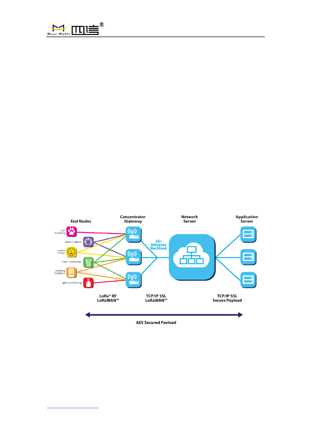
1.3 Working Principle
The principle chart of the F8L10GW LoRa Gatwway is as following:
F8L10GW LoRa Gateway
Page 8 of 37
Add:11th Floor, A-06 Area, No.370, Chengyi Street, Jimei, Xiamen, Fujian, China.
http://www.four-faith.com Tel:+86-592-6307217 Fax: +86-592-5912735
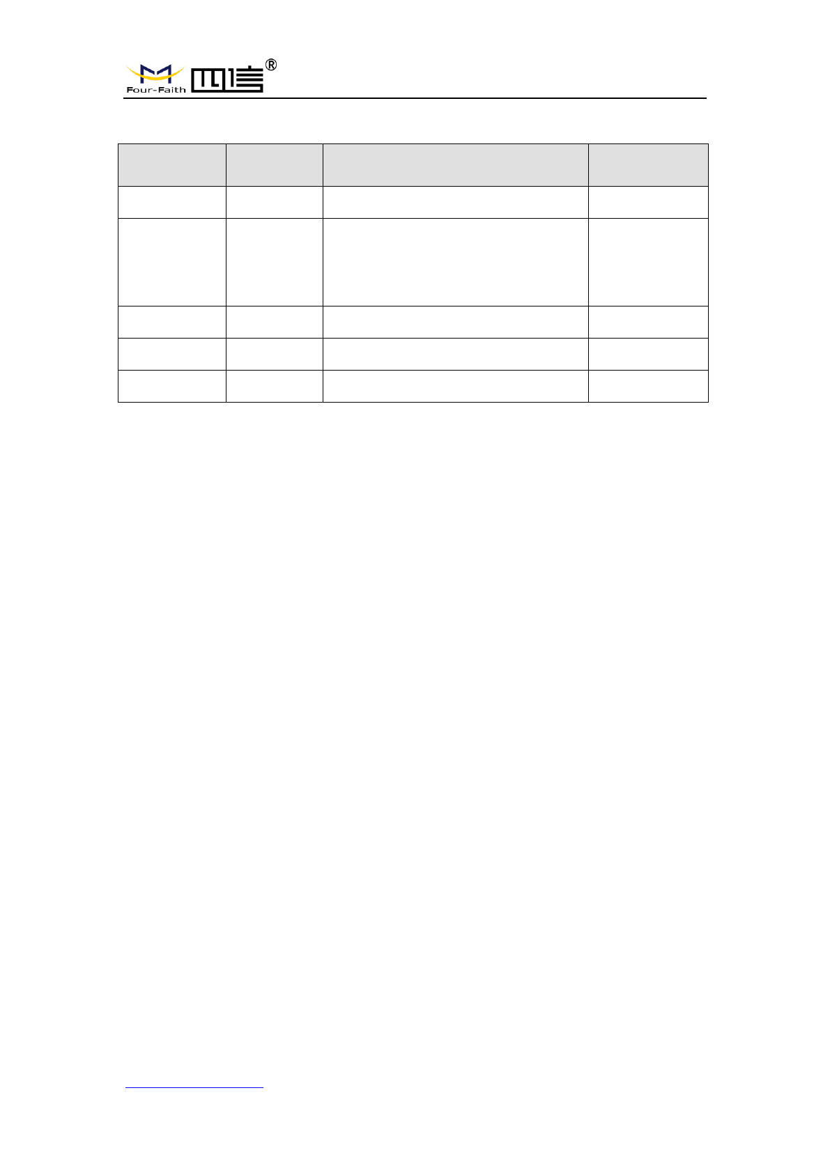
1.4 Specifications
Communication Network: Start topology.
Supported LoRaWAN protocol: Class A and Class B*, Class C.
Supported frequency: EU863-870.
Urban communication range: 6km.
Maximum receiving sensitivity: Max -142dbm @LoRa; -70dbm @WIFI.
8 upstream channels,1 downstream channel.
Safe and reliable, low latency, wireless transmission technology.
Adaptive data rate.
Work mode: support sending and receiving different frequency, same frequency.
Positioning function: GPS.
Network connectivity: 3G / 4G, Ethernet.
Management: WiFi wireless management and upgrade.
TF card local storage supported.
Operating temperature: -35~+50℃.
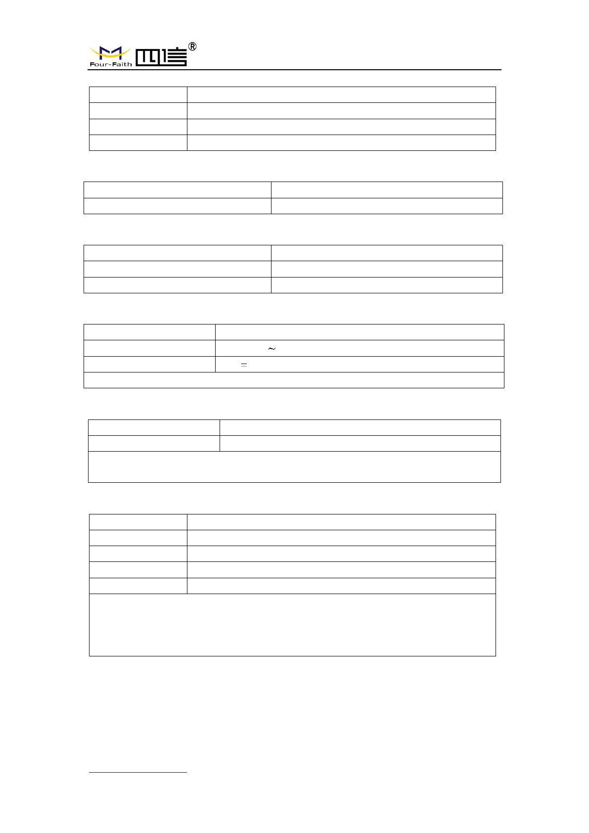
Dimensions: 289.4*223.62*115 mm.
IP65 rated.
Power supply:100-240V 50/60Hz, 0.8A.
Electrical Performance.
No.
Parameter
Technical Data
1
Rated input voltage
100~240V AC
2
Rated output voltage
12V
3
Rated output current
3A
4
Input undervoltage protection
No
5
Output overvoltage protection
Yes
6
Output overcurrent protection
Yes
7
Short circuit protection
Yes
8
Lightning protection level
3KA
9
Input wire diameter
5-7mm
Cellular Specification
ITEM
CONTENT
Frequency Band
FDD-LTE Band 2/4/5/7/17
DC-HSPA/HSPA+/HSDPA/ HSUPA/WCDMA Band 1/8
GSM850 / PCS1900
F8L10GW LoRa Gateway
Page 9 of 37
Add:11th Floor, A-06 Area, No.370, Chengyi Street, Jimei, Xiamen, Fujian, China.
http://www.four-faith.com Tel:+86-592-6307217 Fax: +86-592-5912735
WIFI Specification
Item
Content
Standard
IEEE802.11b/g/n
Security
WEP, WPA, WPA2, etc.
Frequency Range
2412MHz to 2462MHz
LoRa Specification
Item
Content
Communication Protocol and Band
902MHz to 928MHz(US)
GPS RX Specification
Item
Content
Frequency Band
1559MHz to 1610MHz
Operating Frequency:
1575.42MHz
Power supply
Item
Content
Input Power
100-240V 50/60Hz, 0.8A
Output Power
12V 3.0A
Note: The power plug considered as disconnect device of Power Supply.
Environmental Limits
Item
Content
Operating Temperature
-35~50ºC
Note 1: Do not use the products in the environment at too high or too low temperature.
The suitable temperature for the product and accessories is -35℃-50℃.
Antenna Specification
Item
Content
LoRa antenna
N-type female, Omni-Directional FRP Antenna , 2dBi gain
GPS antenna
N-type female, Omni-Directional FRP Antenna , 2dBi gain
WiFi antenna
N-type female, Omni-Directional FRP Antenna , 2dBi gain.
WWAN antenna
N-type female, Omni-Directional FRP Antenna , 0dBi gain
Note 1: Please ensure to use only the antenna offered by the manufacturer. Using
unauthorized antenna may cause danger and violate the authorization
Note 2: Antenna connector ( N-type ) was not unique connector, need installed by
trained, professional engineer

F8L10GW LoRa Gateway
Page 10 of 37
Add:11th Floor, A-06 Area, No.370, Chengyi Street, Jimei, Xiamen, Fujian, China.
http://www.four-faith.com Tel:+86-592-6307217 Fax: +86-592-5912735
Federal Communication Commission (FCC) Radiation Exposure
Statement
The device has been evaluated to meet general RF exposure requirement,
The device can be used in portable exposure condition without restriction
Federal Communication Commission (FCC) Radiation Exposure Statement
Power is so low that no RF exposure calculation is needed.
This device complies with part 15 of the FCC rules. Operation is subject to the
following two conditions: (1) this device may not cause harmful interference,
and (2) this device must accept any interference received, including
interference that may cause undesired operation.
NOTE: The manufacturer is not responsible for any radio or TV interference
caused by unauthorized modifications or changes to this equipment. Such
modifications or changes could void the user’s authority to operate the
equipment.
NOTE: This equipment has been tested and found to comply with the limits for
a Class B digital device, pursuant to part 15 of the FCC Rules. These limits are
designed to provide reasonable protection against harmful interference in a
residential installation. This equipment generates uses and can radiate radio
frequency energy and, if not installed and used in accordance with the
instructions, may cause harmful interference to radio communications.
However, there is no guarantee that interference will not occur in a particular
installation. If this equipment does cause harmful interference to radio or
television reception, which can be determined by turning the equipment off and
on, the user is encouraged to try to correct the interference by one or more of
the following measures:
‐ Reorient or relocate the receiving antenna.
‐ Increase the separation between the equipment and receiver.
‐Connect the equipment into an outlet on a circuit different from that to which
the receiver is connected.
‐Consult the dealer or an experienced radio/TV technician for help.
FCC Caution: Any changes or modifications not expressly approved by the
party responsible for compliance could void the user's authority to operate this
equipment.

F8L10GW LoRa Gateway
Page 11 of 37
Add:11th Floor, A-06 Area, No.370, Chengyi Street, Jimei, Xiamen, Fujian, China.
http://www.four-faith.com Tel:+86-592-6307217 Fax: +86-592-5912735
Chapter 2 Installation Instruction
2.1 General
F8L10GW must be installed correctly in order to achieve the design function. The
installation must be conducted by a qualified engineer recognized by the Four-Faith.
Warning:
1. Power off before installation.
2. Don’t remove the cover, power interface, antenna interface.
2.2 Packing List
2.2.1. Wall-mounted Packing List
Item
Qty
Remark
F8L10GW LoRa Gateway
1
4G Omni-Directional FRP Antenna
1
Optional
WIFI Omni-Directional FRP Antenna
1
GPS Omni-Directional FRP Antenna
1
LoRa Omni-Directional FRP Antenna
1
Bracket
1
Swelling screw ø14mm
3
Wire
1
Optional
User manual CD
1
Optional
QC passed card
1
Warranty card
1
2.2.2. Pole-mounted Packing List
Item
Qty
Remark
F8L10GW gateway
1
4G Omni-Directional FRP Antenna
1
Optional
WIFI Omni-Directional FRP Antenna
1
GPS Omni-Directional FRP Antenna
1
LoRa Omni-Directional FRP Antenna
1
Bracket
2
Wire
1
Optional
User manual CD
1
Optional
F8L10GW LoRa Gateway
Page 12 of 37
Add:11th Floor, A-06 Area, No.370, Chengyi Street, Jimei, Xiamen, Fujian, China.
http://www.four-faith.com Tel:+86-592-6307217 Fax: +86-592-5912735
QC passed card
1
Warranty card
1
2.3 Installation
F8L10GW Dimensions
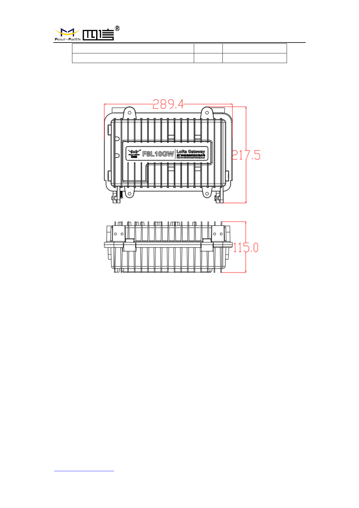
2.3.1 SIM/UIM Installation
1. Cut off the power.
2. Unscrew the M6 screws, figure. 2.3.1 as below.
3. Insert SIM/UIM card, figure 2.3.2 as below.
4. Push the SIM/UIM card and the card will pop up automatically.
5. Tighten M6 screws.
Warning:
1. Power must be off before installing SIM/UIM card.
2. M6 screws must be tightened and fixed.
F8L10GW LoRa Gateway
Page 13 of 37
Add:11th Floor, A-06 Area, No.370, Chengyi Street, Jimei, Xiamen, Fujian, China.
http://www.four-faith.com Tel:+86-592-6307217 Fax: +86-592-5912735
Figure 2-3-1 Unscrew the M6 screws
Figure 2-3-2 Insert SIM/UIM card
2.3.2 Wall-mounted Installation
Step 1: The wall where the gateway is installed must be flat and open-sided, make
sure no shield within 5 meters around LoRa antenna. Drill 3 holes of ø14mm
diameter, 60 mm depth (swelling screw is about 50mm long) according to the
position of the bracket mounting holes, Figure 2-3-3.
(Note: Press the shelf against the wall, mark it, and then punch the hole in the wall.)

F8L10GW LoRa Gateway
Page 14 of 37
Add:11th Floor, A-06 Area, No.370, Chengyi Street, Jimei, Xiamen, Fujian, China.
http://www.four-faith.com Tel:+86-592-6307217 Fax: +86-592-5912735
Figure 2-3-3 Hole Location Diagram
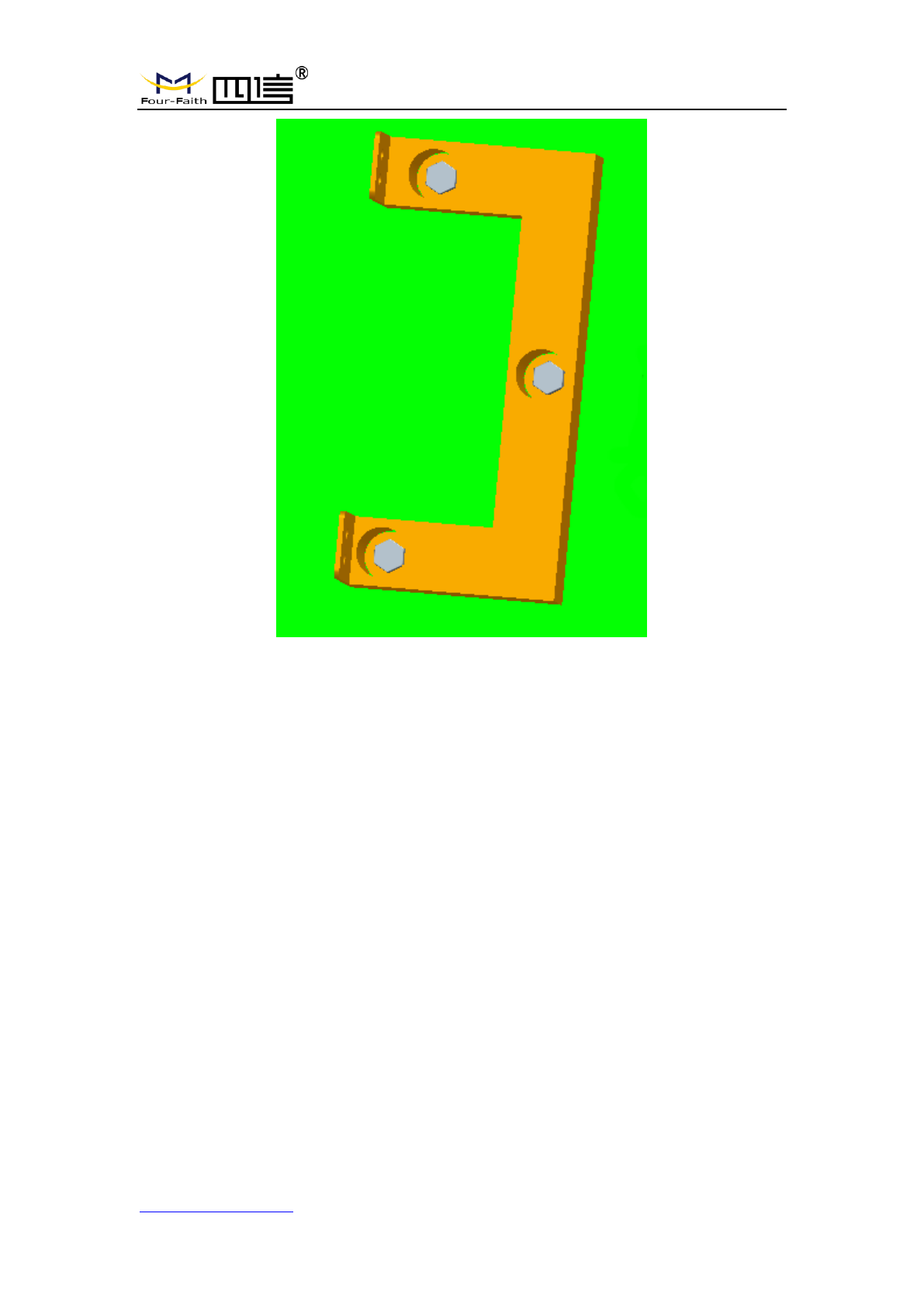
Step 2: Fix the swelling screws in the bracket, Figure 2-3-4.
Figure 2-3-4 Swelling Screws Installation Diagram
Step 3: Fix the bracket on the wall and tighten the screw, Figure 2-3-5.
F8L10GW LoRa Gateway
Page 15 of 37
Add:11th Floor, A-06 Area, No.370, Chengyi Street, Jimei, Xiamen, Fujian, China.
http://www.four-faith.com Tel:+86-592-6307217 Fax: +86-592-5912735
Figure 2-3-5 Bracket Installation Diagram
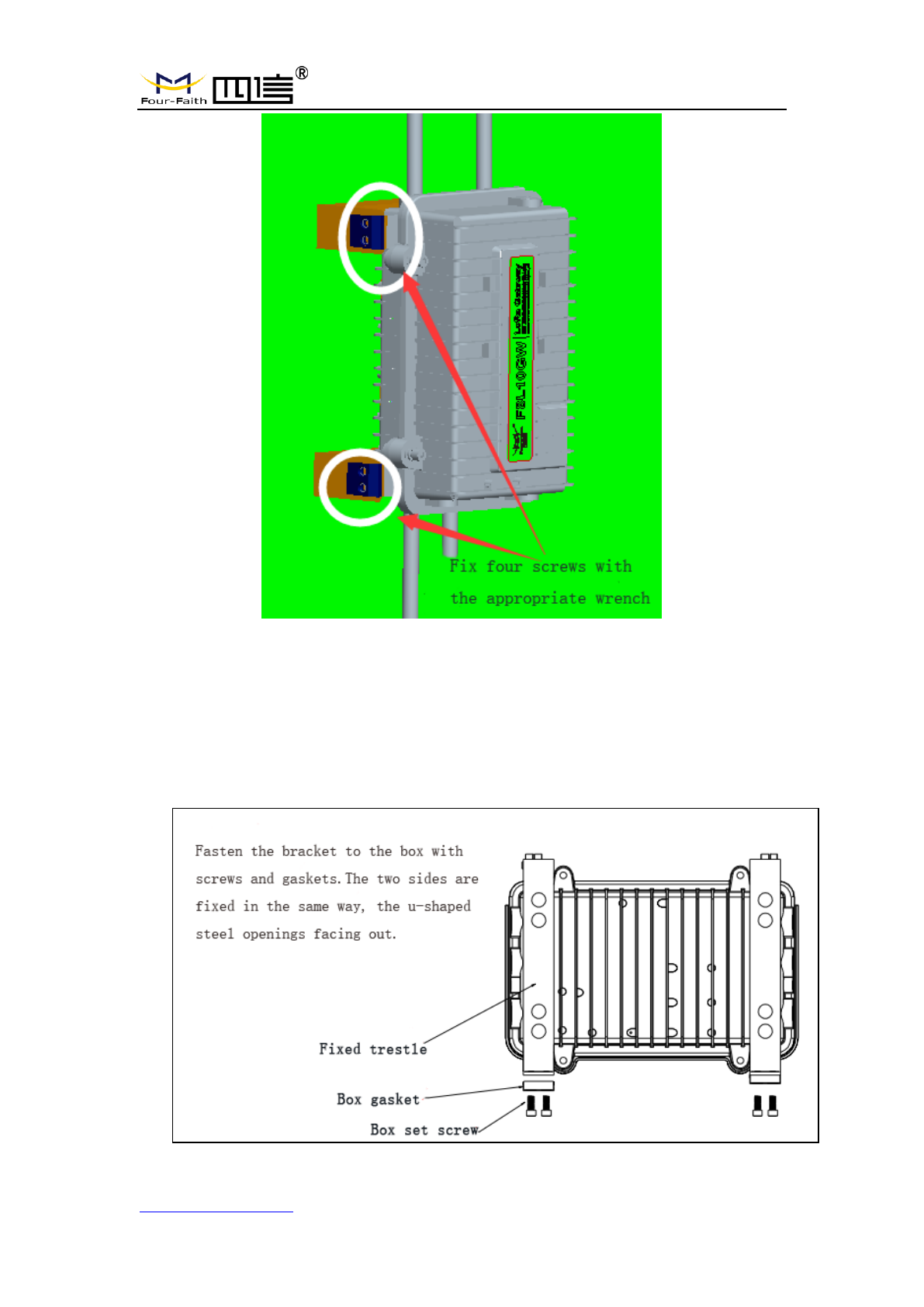
Step 4: Tighten the four screws and fix the gateway on the bracket, then install the
antenna, Figure 2-3-6.
F8L10GW LoRa Gateway
Page 16 of 37
Add:11th Floor, A-06 Area, No.370, Chengyi Street, Jimei, Xiamen, Fujian, China.
http://www.four-faith.com Tel:+86-592-6307217 Fax: +86-592-5912735
Figure 2-3-6 Fix Four Screws Diagram
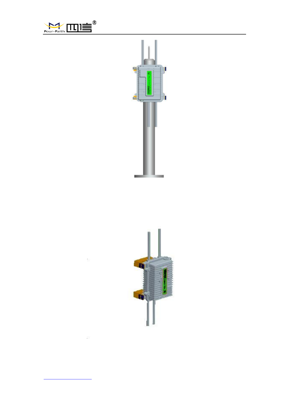
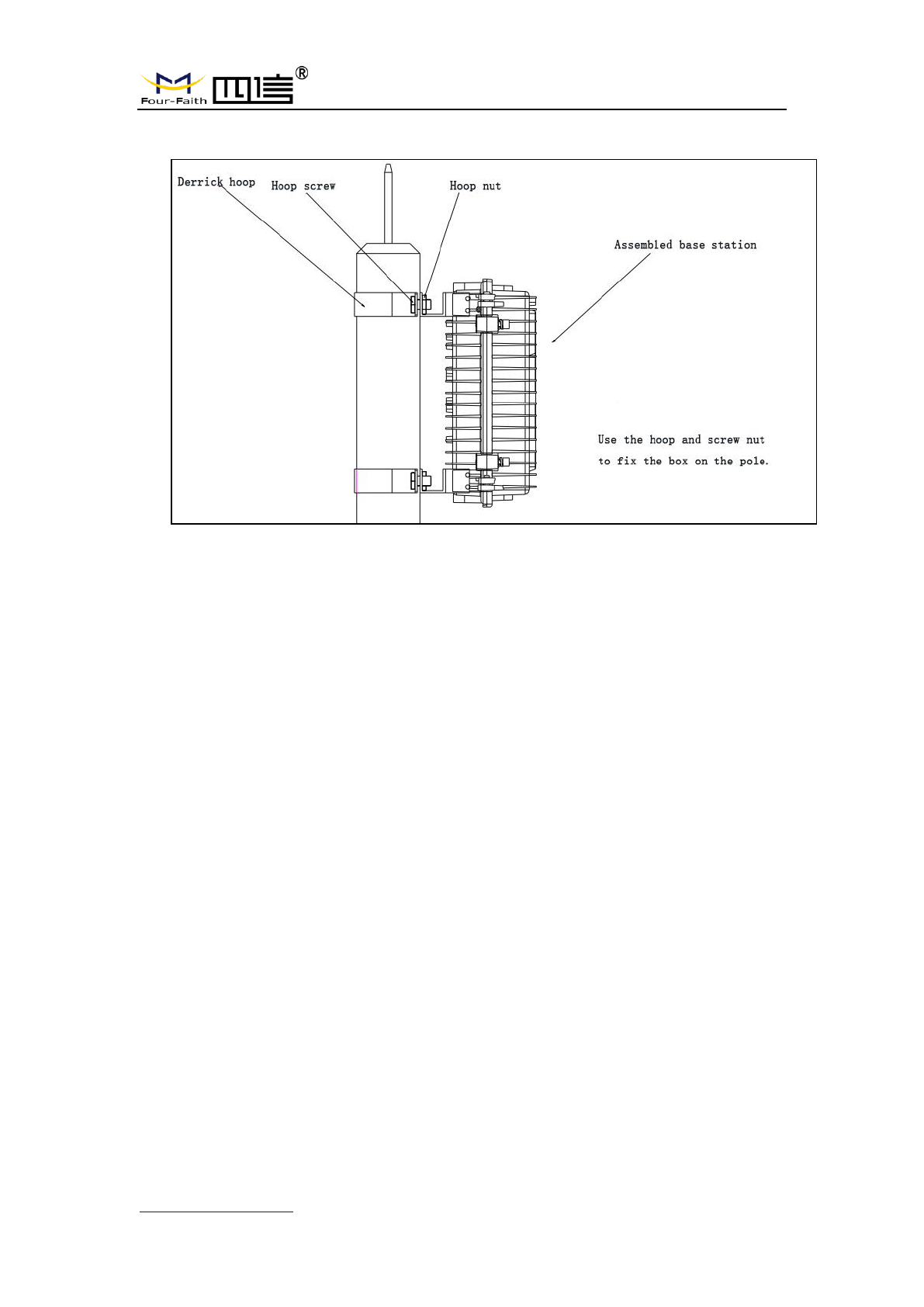
2.3.3 Pole-mounted Installation
Step 1: Prepare a pole with 70~90mm diameter, make sure no shield within 5
meters around LoRa antenna.
Step 2: Put the clamp into the pole, fix the clamp in the pole with screws.
F8L10GW LoRa Gateway
Page 17 of 37
Add:11th Floor, A-06 Area, No.370, Chengyi Street, Jimei, Xiamen, Fujian, China.
http://www.four-faith.com Tel:+86-592-6307217 Fax: +86-592-5912735
Note: Pole is not included in the product.
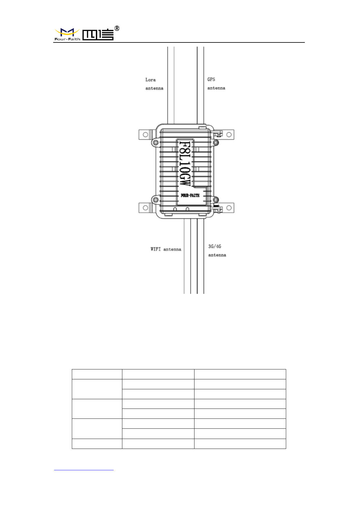
2.3.4 Antenna Installation
After gateway is installed on the wall or pole, connect the Matching antennas to the
antenna interface.Make sure the antennas are tightened to get best signal. Fig. 2.3.7
Note: Each antenna must install to the right interface and Using a tool to tighten,
otherwise the gateway won’t work properly and waterproof.
F8L10GW LoRa Gateway
Page 18 of 37
Add:11th Floor, A-06 Area, No.370, Chengyi Street, Jimei, Xiamen, Fujian, China.
http://www.four-faith.com Tel:+86-592-6307217 Fax: +86-592-5912735
Fig. 2.3.7
2.4 Indicator light description
The F8L10GW offers the following indicators: Power, System, Online, SIM, LoRa,
WAN, WIFI, Signal Strength. Status description of each indicator are as below:
Indicator light
Status
Description
PWR
Red light on
Power on
Red light off
Power off
SYS
Yellow light flash
System work properly
Yellow light off
System work improperly
WIFI
Blue light on
WIFI on
Blue light off
WIFI off
LoRa
Green light on
LoRa normal

F8L10GW LoRa Gateway
Page 19 of 37
Add:11th Floor, A-06 Area, No.370, Chengyi Street, Jimei, Xiamen, Fujian, China.
http://www.four-faith.com Tel:+86-592-6307217 Fax: +86-592-5912735
Green light off
LoRa abnormal
Green light flash
Data Transmitting
3G/4G Signal
Turn on an light
Weak signal strength (less
than -90db)
Turn on two lights
Medium signal strength
(-70db~-90db)
Turn on three lights
Better signal strength (greater
than -70db)
Online
Green light off
Online
Green light on
Offline
F8L10GW LoRa Gateway
Page 20 of 37
Add:11th Floor, A-06 Area, No.370, Chengyi Street, Jimei, Xiamen, Fujian, China.
http://www.four-faith.com Tel:+86-592-6307217 Fax: +86-592-5912735
Chapter 3 Configuration
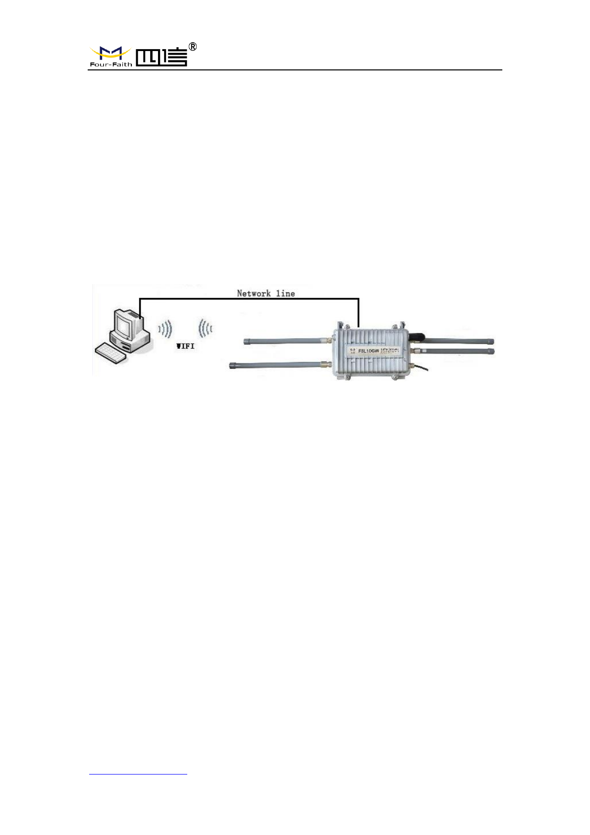
3.1 Configuration Connection
Before configuring the F8L10GW, connect the F8L10GW and the PC network cable or
WIFI. When connect with network cable, one end is connected to any Ethernet interface of
F8L10GW "Local Network" (LAN port), and the other end is connected to the Ethernet
interface of PC. When connect with WIFI, the default SSID of F8L10GW is "FOUR-FAITH"
without password verification.
3.2 Access to Configuration Web Page
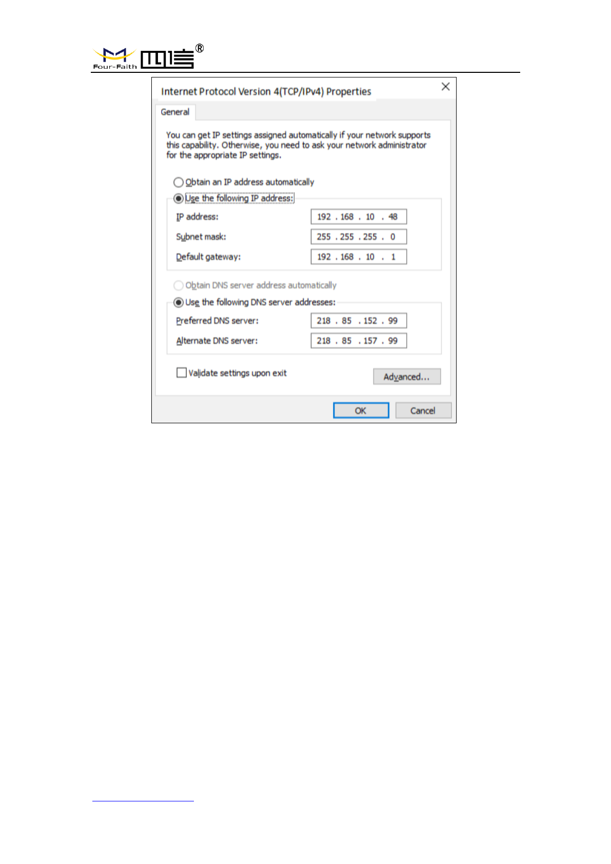
3.2.1 IP Address Setting
Specify IP address
Set the IP address of PC as 192.168.1.9(or other IP address of 192.168.1 network
segment), the subnet mask as 255.255.255.0, and the default gateway as
192.168.1.1.DNS as a locally available DNS server.
F8L10GW LoRa Gateway
Page 21 of 37
Add:11th Floor, A-06 Area, No.370, Chengyi Street, Jimei, Xiamen, Fujian, China.
http://www.four-faith.com Tel:+86-592-6307217 Fax: +86-592-5912735
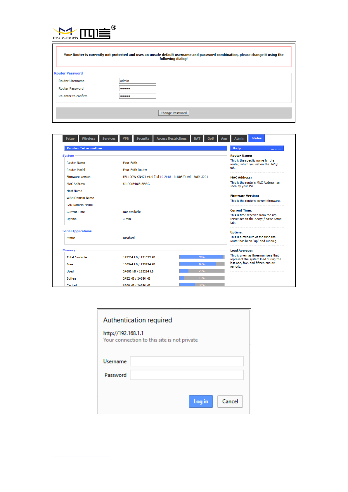
3.2.2 Login configuration web page
This chapter describes the main functions of the relevant pages. Visit the web pages
via web browser by the computer connected to F8L10GW. There are 11 main pages:
Settings, Wireless, Service, VPN, Security, Access Restrictions, NAT, QoS Settings,
Applications, Management and Status. Users enable to browse slave pages by click one
main page. This manual introduces the parameters related to F8L10GW, other
parameters can be default.
To access F8L10GW web-based Web management tool, enter the default IP address
192.168.1.1 of the F8L10GW in the address bar of browser, press enter. When login the
web page in the first time, there will display a page shows as blow to tip users to modify
the default user name and password. User can click “Change Password” to modify user
name and password if needed.
F8L10GW LoRa Gateway
Page 22 of 37
Add:11th Floor, A-06 Area, No.370, Chengyi Street, Jimei, Xiamen, Fujian, China.
http://www.four-faith.com Tel:+86-592-6307217 Fax: +86-592-5912735
Then access to main page.
Users need to enter user name and password if it is the first time to login.
Enter username and password to access the web page, default username and
password are both “admin”. (You can change the username and password on
F8L10GW LoRa Gateway
Page 23 of 37
Add:11th Floor, A-06 Area, No.370, Chengyi Street, Jimei, Xiamen, Fujian, China.
http://www.four-faith.com Tel:+86-592-6307217 Fax: +86-592-5912735
administration page.) then click “OK”.
3.3 Management & Configuration
3.3.1 Connection Setting
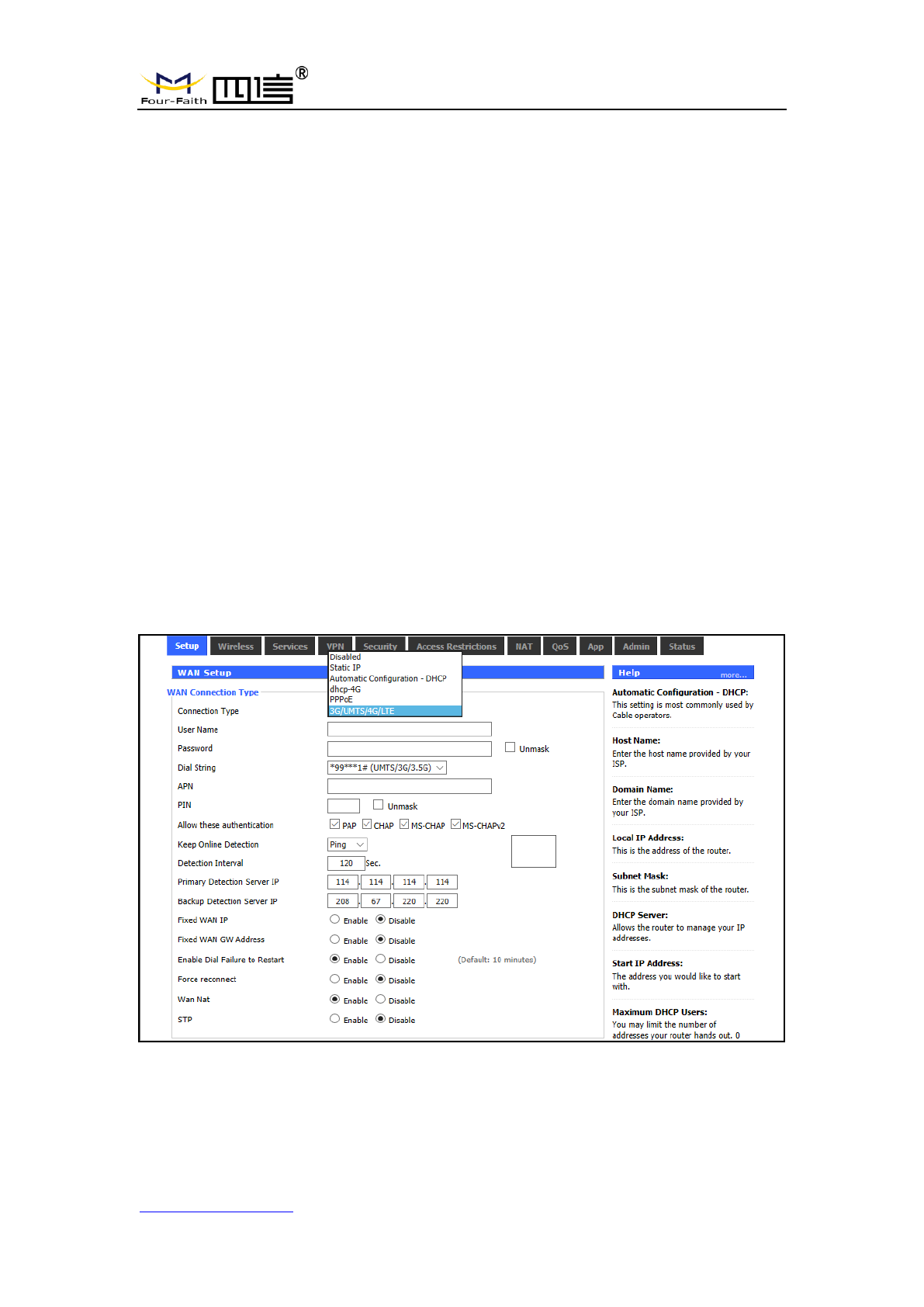
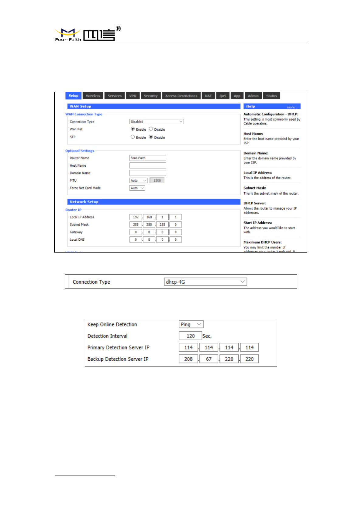
Click “Settings” and open first basic setting web page. On this page, change basic
settings according to the notices, click "Save” button to change the setting but don't take
effect, click "Apply" button to make settings to take effect, or click "Cancel" button to
cancel the settings.
Basic Settings:
“WAN Connection Type” setting section describes how to configure F8L10GW to
connect to the Internet. Details on this can be obtained from your ISP.
WAN Connection Type
Select the Internet connection type provided by your ISP from the drop-down menu,
WAN connection type includes 7 modes: Disable, Static IP, Automatic Configuration -
DHCP, PPPOE, 3G/UMTS/4G/LTE and DHCP-4G. The F8L10GW (LAN port only)
provides wired Ethernet connections and DHCP-4G (default) connections.
Mode 1: Wired Ethernet connection
F8L10GW LoRa Gateway
Page 24 of 37
Add:11th Floor, A-06 Area, No.370, Chengyi Street, Jimei, Xiamen, Fujian, China.
http://www.four-faith.com Tel:+86-592-6307217 Fax: +86-592-5912735
In the menu "WAN Settings" - > "WAN Connection Type" - > "Connection Type" select
"Disabled", in the menu of "Network Settings" - > "Router IP Configuration" Set IP address
of gateway with the same LAN IP.Then Wired Ethernet Connection is finished.
Mode 2: DHCP-4G
The IP address of the WAN port is obtained by dhcp-4G
Keep Online
This function is to detect whether the Internet connection is active. If users set it, the
F8L10GW will automatically detect the Internet connection. Once gateway detects the link
disconnected or invalid, the system will automatically reconnect and re-establish the
effective connection. If network is busy or in private network, Router mode is
recommended.
Keep Online:
None: disable Keep Online function.
Ping: Send ping packet to detect connection. In this mode, "Detection Interval",
F8L10GW LoRa Gateway
Page 25 of 37
Add:11th Floor, A-06 Area, No.370, Chengyi Street, Jimei, Xiamen, Fujian, China.
http://www.four-faith.com Tel:+86-592-6307217 Fax: +86-592-5912735
"Primary Detection Server IP" and "Backup Detection Server IP" must be configured
correctly.
Route: Detect connection with route method. In this mode, "Detection Interval",
"Primary Detection Server IP" and "Backup Detection Server IP" must be configured
correctly.
PPP: The PPP mode is to detect connection. In this mode, "Detection Interval" must
be configured correctly.
Detection Interval: time interval between two detection, unit is second
Primary Detection Server IP: Primary server IP used to response gateway’s
detection packet.This item is only valid for "Ping" and "Route".
Backup Detection Server IP: Backup server IP used to response gateway’s
detection packet. This item is only valid for "Ping" and "Route".
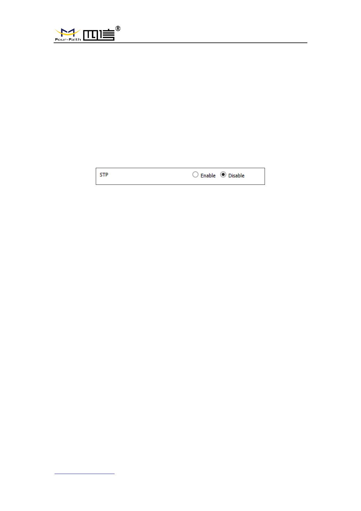
STP
STP(Spanning Tree Protocol)can be applied to the loop network, Through certain
algorithm achieves path redundancy, and loop network cuts to tree-based network without
loop in the meantime, thus to avoid the hyperplasia and infinite circulation of a message in
the loop network .
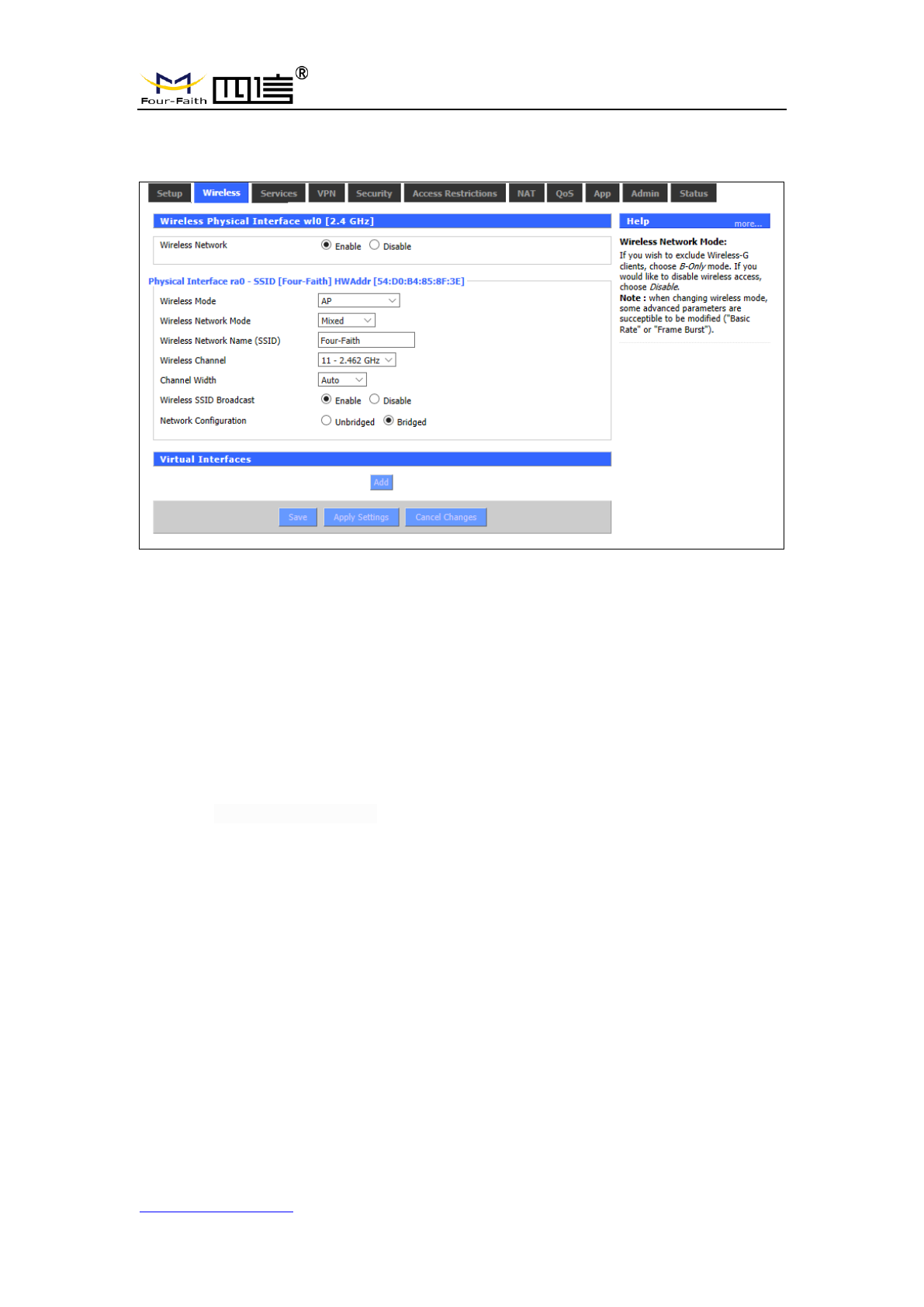
3.3.2 WiFi
WiFi function of F8L10GW gateway/gateway is to provide parameter configuration and
online upgrade.
F8L10GW LoRa Gateway
Page 26 of 37
Add:11th Floor, A-06 Area, No.370, Chengyi Street, Jimei, Xiamen, Fujian, China.
http://www.four-faith.com Tel:+86-592-6307217 Fax: +86-592-5912735
3.3.2.1 Basic Configuration
Enable: Turn on WIFI.
Disable: Turn off WIFI.
Wireless mode: AP, client, ad-hoc, relay and relay bridge are available.
Wireless network mode:
Hybrid: Support wireless devices with 802.11b/g/n standards at the same time
Bg-mix: Support both 802.11b and 802.11g standards wireless devices.
B Only: Only 802.11b standard wireless devices are supported.
G Only: Only 802.11g standard wireless devices are supported.
NG-mix: It supports 802.11g and 802.11n wireless devices.
Only N: Only 802.11n standard wireless devices are supported.
8021.11n transmission mode: When the wireless network mode is "only N", select its
transmission modes:
Greenbelt: When sure that no other 802.11a/b/g device in the surrounding environment
using the same channel, using this mode or increasing throughput. If there are
other 802.11a/b/g devices in the environment that using the same channel, the
messages you send can be errors, re-sends, and so on.
Mixture:This model is the opposite of the greenbelt model, but it reduces throughput.
Wireless network name (SSID): The network name Shared by all devices in a wireless
network, and the SSID of all devices is the same.SSID
consists of Numbers and letters, case - sensitive, no
more than 32 characters.
Wireless channels: there are 1-13 channels available. In the environment of multiple
wireless devices, please try to avoid using the same channels as
other devices.
F8L10GW LoRa Gateway
Page 27 of 37
Add:11th Floor, A-06 Area, No.370, Chengyi Street, Jimei, Xiamen, Fujian, China.
http://www.four-faith.com Tel:+86-592-6307217 Fax: +86-592-5912735
Channel width: 20MHZ and 40MHZ are available.
Broadband: when the channel is 40MHZ, you can choose upper or lower.
Wireless SSID Broadcast:
Enable: broadcast SSID.
Disable: hide SSID.
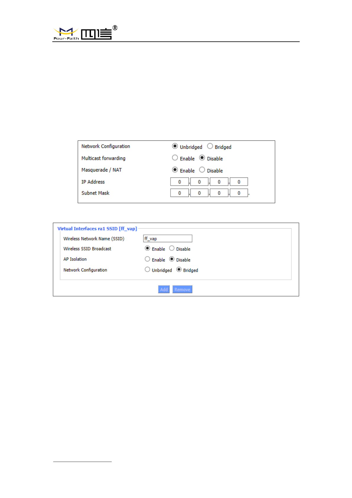
Network configuration:
Bridged: the bridge is connected to F8L10GW. In general, select bridged.
Unbridged: when no bridge is connected to F8L10GW, and the IP address needs
to be manually configured.
Virtual interface:Click to add a virtual interface, after successfully addition, click to
remove the virtual interface.
AP independence: completely isolate all wireless client devices so that they can only
access a fixed network with AP connections.
Note: save settings: save your changes, after changing the mode of "wireless", "wireless
network model", "wireless width" and "broadband" option, please click on this button, and
then configure other options.
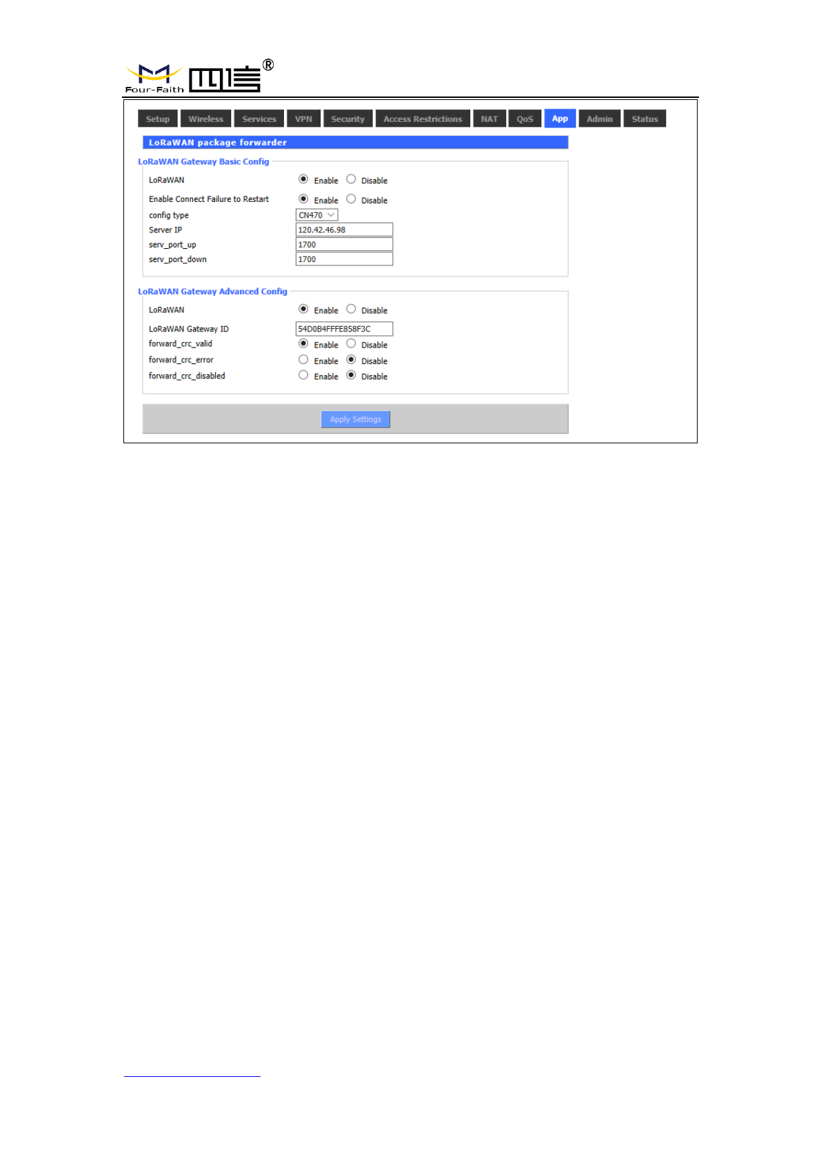
3.3.3 LoRa Application
Users can configure the parameters of forwarding function of LoRa gateway according
to the requirements.
F8L10GW LoRa Gateway
Page 28 of 37
Add:11th Floor, A-06 Area, No.370, Chengyi Street, Jimei, Xiamen, Fujian, China.
http://www.four-faith.com Tel:+86-592-6307217 Fax: +86-592-5912735
LoRa Gateway infrastructure configuration:
Enable the failed restart mechanism: when the gateway connection server fails, the
restart mechanism will start working.
Server address: the IP address of LoRaWAN data service center
Server upstream port: LoRaWAN data service center program uplink port. The range
is 0-65535 and the default value is 1700.
Server downstream port: LoRaWAN data service center program downlink port. The
range is 0-65535 and the default value is 1700.
Advanced configuration of LoRa Gateway:
LoRa Gateway ID: the unique identity of the LoRa Gateway, through which the server
can distinguish different LoRa Gateway.
CRC validation ok: Turn on/off CRC for validation. Default is on.
CRC validation error: Turn on or off the CRC validation error function. The default is
close.
CRC validation disabled: Turn on or off CRC validation. The default is close.
3.3.4 ADMINISTER
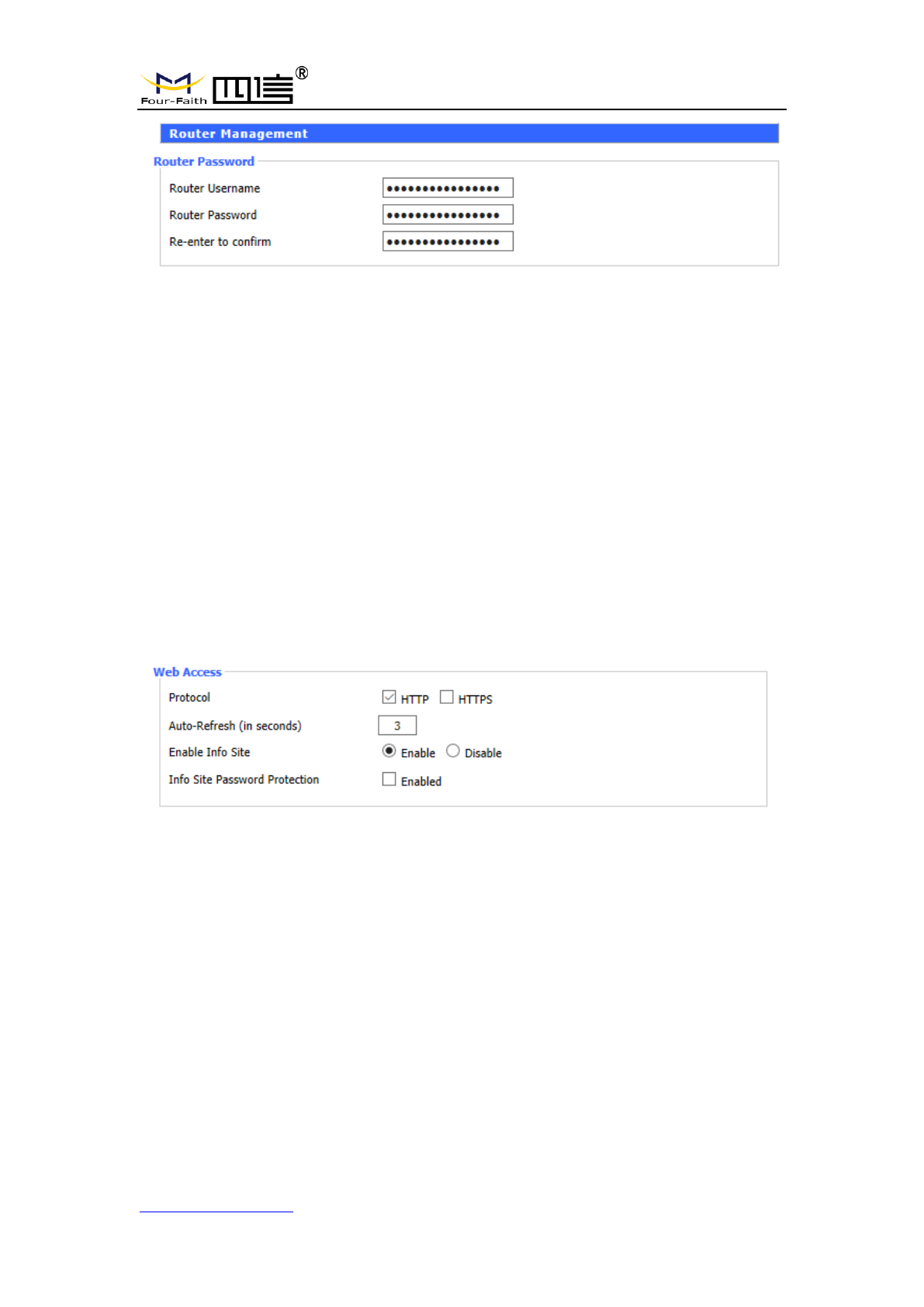
3.3.4.1 ADMINISTER
This page allows network administrators to manage specific F8L10GW functions to
ensure access and security.
F8L10GW LoRa Gateway
Page 29 of 37
Add:11th Floor, A-06 Area, No.370, Chengyi Street, Jimei, Xiamen, Fujian, China.
http://www.four-faith.com Tel:+86-592-6307217 Fax: +86-592-5912735
The new password shall not exceed 32 characters in length and shall not contain any
spaces. Make sure your password is the same as your new password, or it will fail.
Warning:
The default username: admin.
We strongly recommend that you modify the factory default password, all users trying
to access and modify the F8L10GW should use the correct F8L10GW password, thus
they can access and use it.
Web Access
This feature allows you to manage F8L10GW using either the HTTP protocol or the
HTTPS protocol. If you choose to disable this feature, you will need to reboot manually.
You can also activate or disable the F8L10GW information page.
That way you can use a password to protect the page (enter the correct username and
password).
Protocols: protocols support web pages include HTTP and HTTPS.
Automatic refresh (second): adjust the time interval for automatic refresh of Web
interface. 0 means turn off this feature.
Display system information page before login: whether to enable display system
information page before login.
System information page password protection: whether to enable the system
information page password protection function.
F8L10GW LoRa Gateway
Page 30 of 37
Add:11th Floor, A-06 Area, No.370, Chengyi Street, Jimei, Xiamen, Fujian, China.
http://www.four-faith.com Tel:+86-592-6307217 Fax: +86-592-5912735
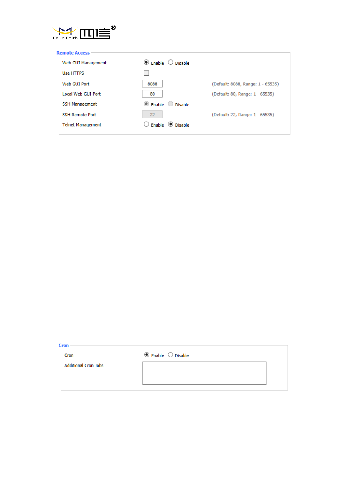
Web interface management: this feature allows you to manage F8L10GW from a remote
location over the Internet. To disable this feature, keep the default Settings. To enable this
feature, select enable and remotely manage F8L10GW using the specified port on your
computer (default is 8080). If you have not yet set the password, you must set the default
password for your own F8L10GW.
For remote management F8L10GW, go to http://xxx.xxx.xxx.xxx:8080 (x represents
F8L10GW Internet IP address, 8080 on behalf of the specified port) in your web browser
address bar. You will be requested to enter the F8L10GW password.
If you are using HTTPS, you need to specify the URL to https://xxx.xxx.xxx.xxx:8080 (not
all firmware support the reconstruction of the SSL)
SSH management: you can enable SSH to secure remote access to F8L10GW.Note that
to understand the setup of the SSH daemon, you can access more content on the service
page.
Warning:
If the remote F8L10GW access function is enabled, anyone who knows the Internet IP
address and password of F8L10GW can change the setting of F8L10GW.
Telnet management: Enable or disable remote Telnet functionality.
Cron:Cron's subsystem is the Linux command you plan to execute. You will need to
use the command line or startup script in actual use.
F8L10GW LoRa Gateway
Page 31 of 37
Add:11th Floor, A-06 Area, No.370, Chengyi Street, Jimei, Xiamen, Fujian, China.
http://www.four-faith.com Tel:+86-592-6307217 Fax: +86-592-5912735
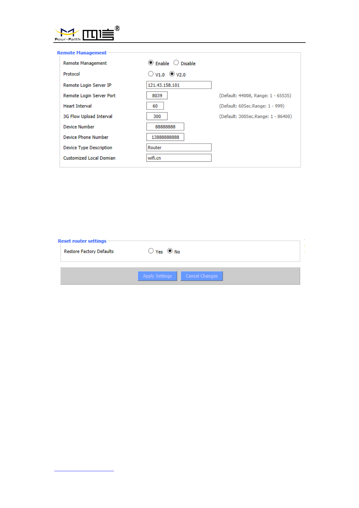
Equipment management: The F8L10GW can be monitored and managed, parameter
configuration, WIFI advertising update through the customized remote management
server.
3.3.4.2 The factory default
To clear all configurations and restore to factory default values, click “Yes” button and
save. All the Settings will lose when revert to the default Settings. The default
configuration for this feature is “No”. For more information, click “More”.
F8L10GW LoRa Gateway
Page 32 of 37
Add:11th Floor, A-06 Area, No.370, Chengyi Street, Jimei, Xiamen, Fujian, China.
http://www.four-faith.com Tel:+86-592-6307217 Fax: +86-592-5912735
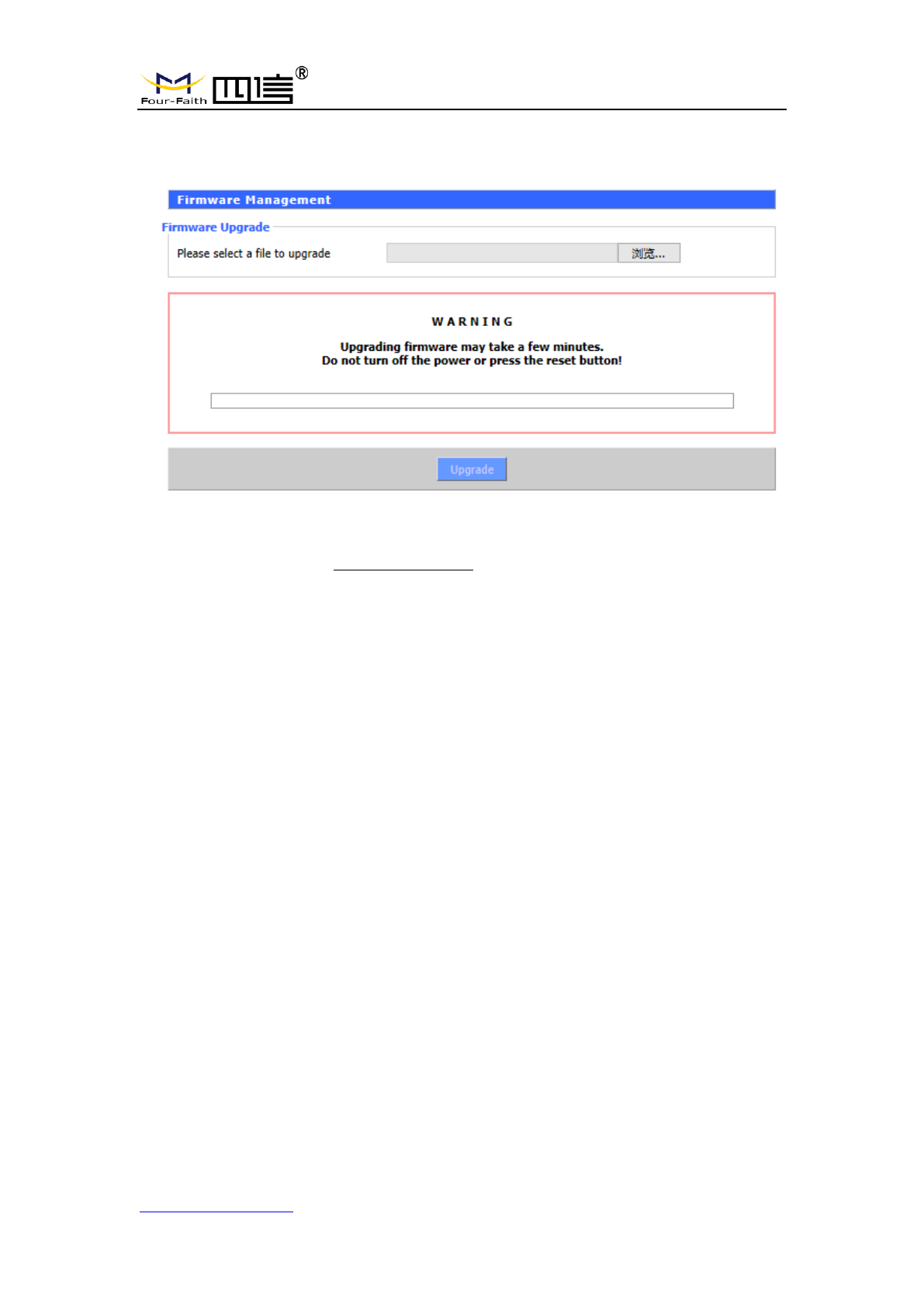
3.3.4.3 Firmware Upgrade
Firmware upgrade: new firmware can be loaded onto F8L10GW.The new firmware
version will be available at www.four-faith.com for free. It is no essential to download the
updated firmware version that F8L10GW work, unless there is useful functionality in new
version.
Note: Upgrading of F8L10GW firmware may lose the configuration Settings. It is essential
to back up the setup information of F8L10GW before upgrading.
After the refresh, reset to: Click “Default Settings” to reset the default Settings of the
firmware version of F8L10GW after the upgrade.
Click browse, select the upgrading firmware file, and then click the “Upgrade” button to
start. It may take few minutes, please do not turn off the power or press the reset button
during this period.
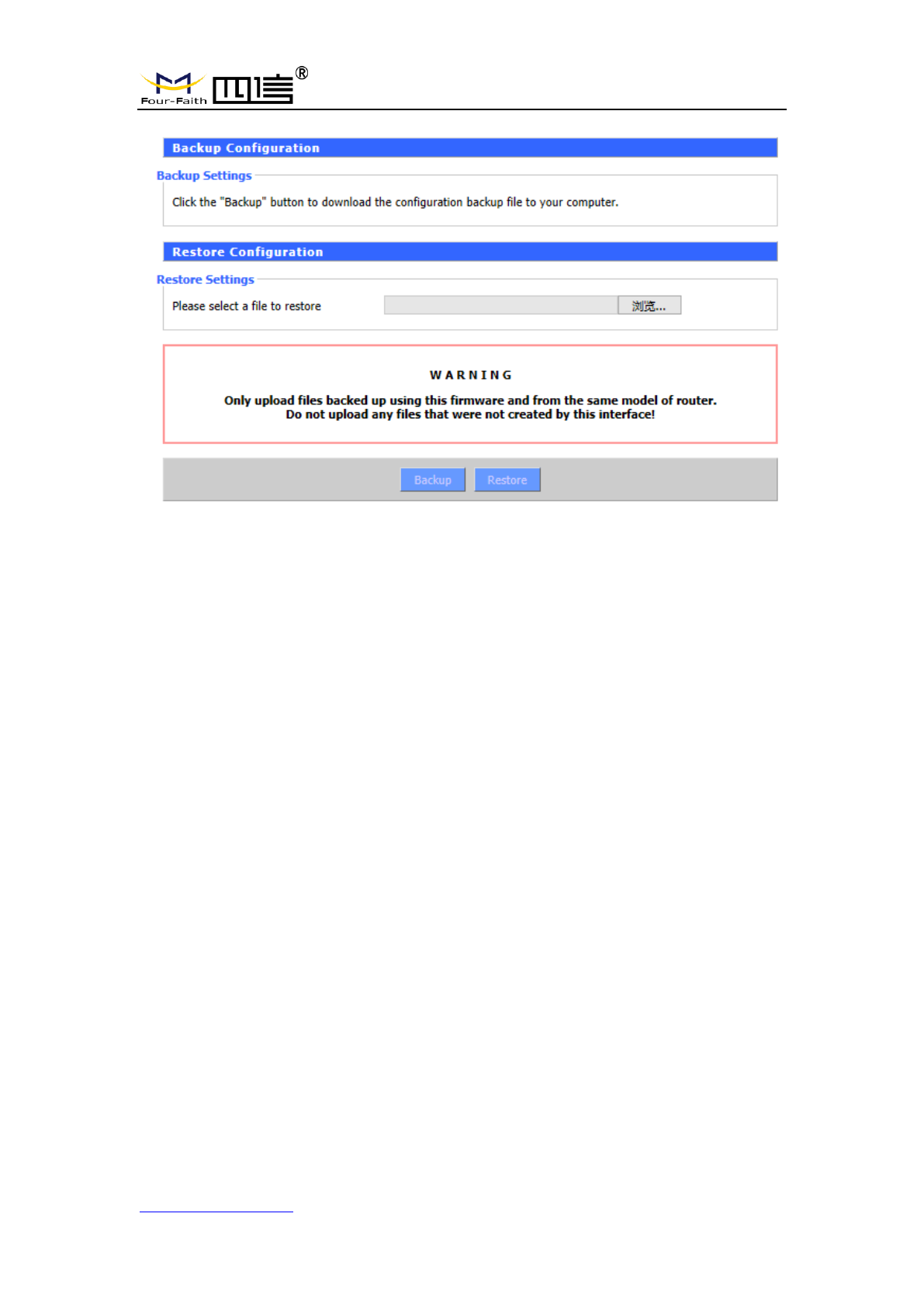
3.3.4.4 Backup
This page is used to back up or restore the F8L10GW configuration file.
F8L10GW LoRa Gateway
Page 33 of 37
Add:11th Floor, A-06 Area, No.370, Chengyi Street, Jimei, Xiamen, Fujian, China.
http://www.four-faith.com Tel:+86-592-6307217 Fax: +86-592-5912735
To backup the F8L10GW configuration file, click the “Backup” button. After that, follow
the instructions on the screen.
To restore the F8L10GW configuration file, click the "Browse" button. After finding the
backup file, follow the instructions on the screen. Select the backup file and click the
“Restore” button.
F8L10GW LoRa Gateway
Page 34 of 37
Add:11th Floor, A-06 Area, No.370, Chengyi Street, Jimei, Xiamen, Fujian, China.
http://www.four-faith.com Tel:+86-592-6307217 Fax: +86-592-5912735
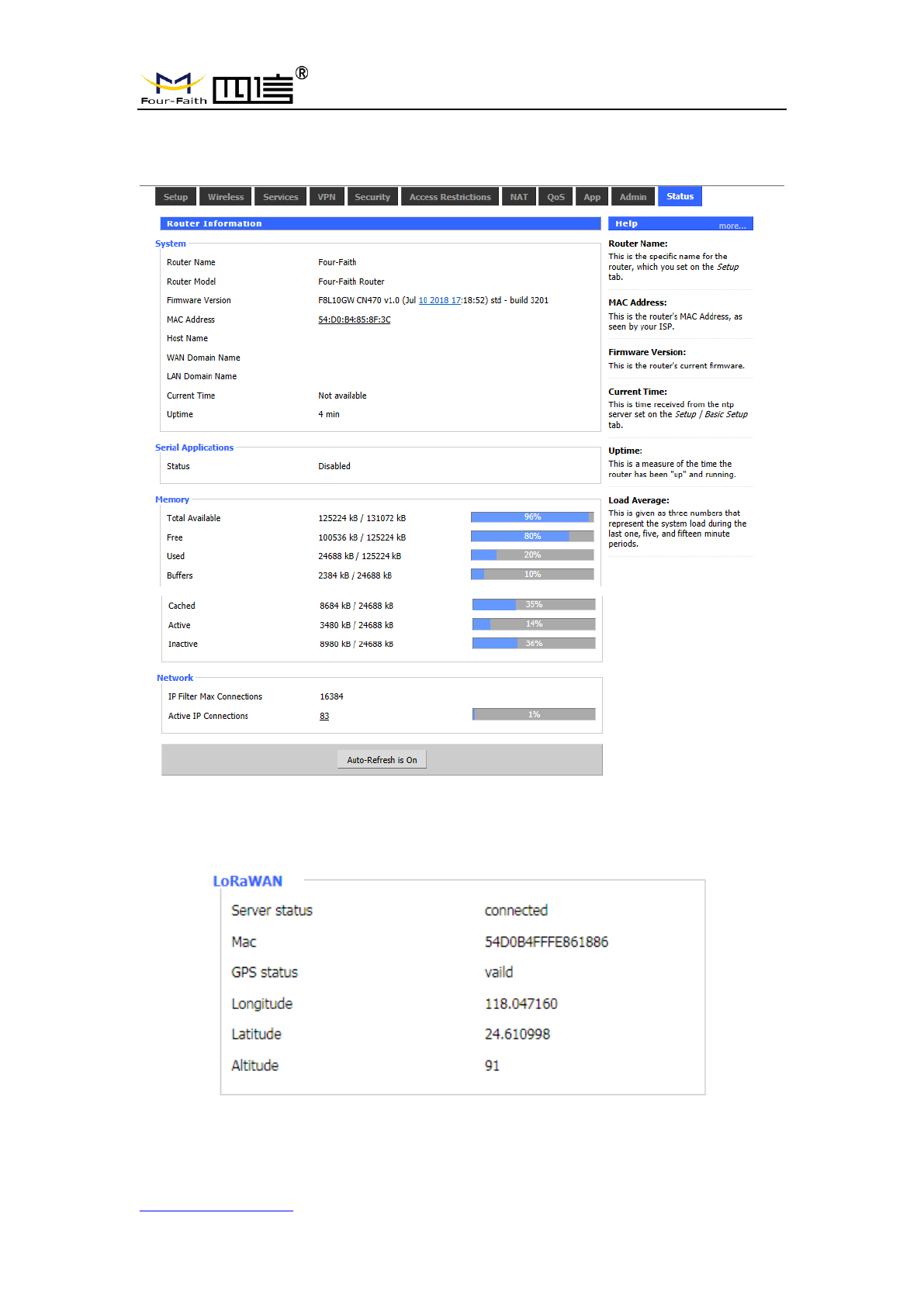
3.3.5 State
3.3.5.1 F8L10GW
Server status: connection status to the specified LoRaWAN server.

F8L10GW LoRa Gateway
Page 35 of 37
Add:11th Floor, A-06 Area, No.370, Chengyi Street, Jimei, Xiamen, Fujian, China.
http://www.four-faith.com Tel:+86-592-6307217 Fax: +86-592-5912735
Mac: Mac address of F8L10GW, LoRaWAN server identification code of different
F8L10GW.
GPS status: it is GPS signal status indicator.
Longitude, dimension and altitude are obtained from GPS.
F8L10GW LoRa Gateway
Page 36 of 37
Add:11th Floor, A-06 Area, No.370, Chengyi Street, Jimei, Xiamen, Fujian, China.
http://www.four-faith.com Tel:+86-592-6307217 Fax: +86-592-5912735
Appendix
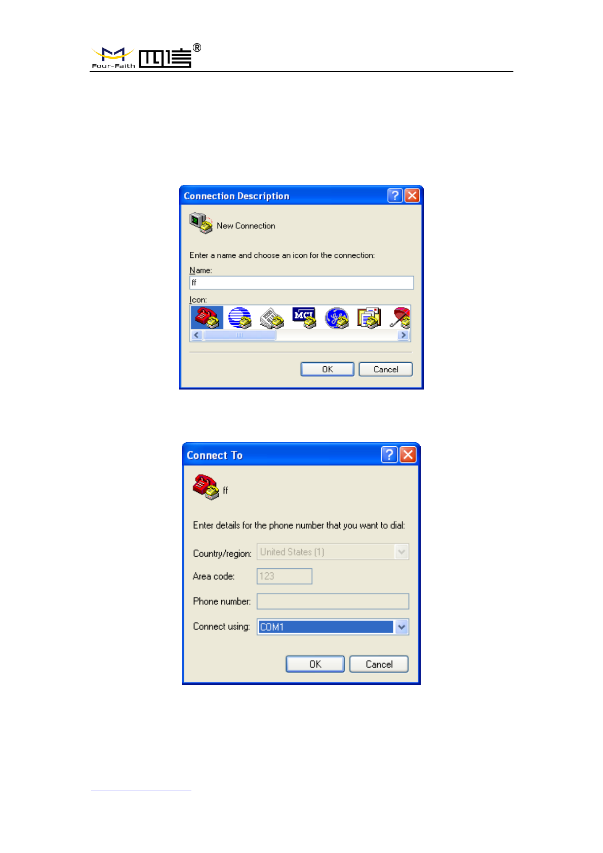
The following steps describe how to make F8L10GW Gateway enter configure state
with the Windows XP Hyper Terminal.
1. Press “Start””Programs””Accessories””Communications””Hyper Terminal”.
2. Enter the connection name and select “OK”.
3. Select the actual physical serial port of PC that is used to connect to the F8L10GW
Console port, and select "OK".
4. Configure the super terminal as shown below and select “OK”.
Communication rate: 115200
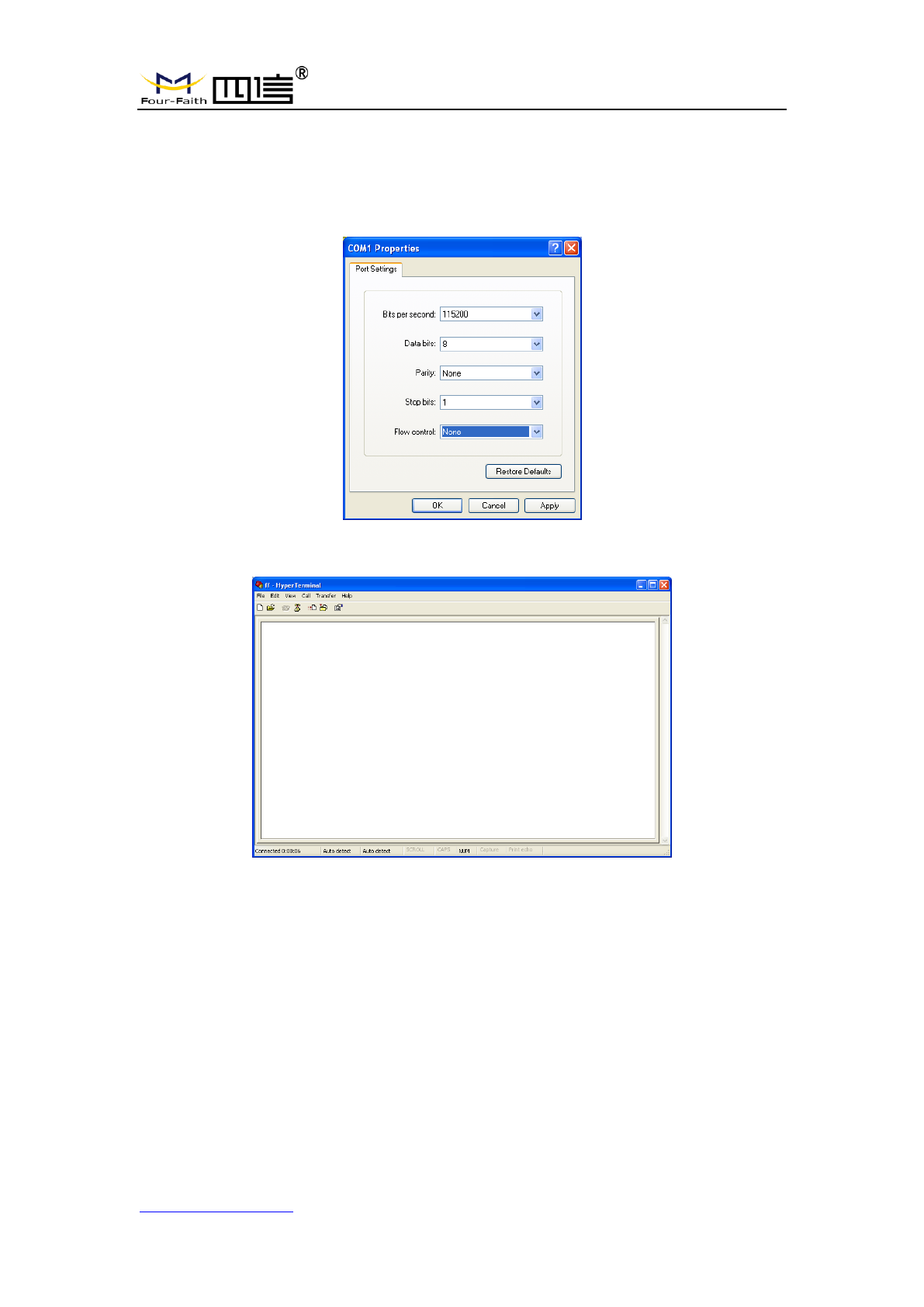
F8L10GW LoRa Gateway
Page 37 of 37
Add:11th Floor, A-06 Area, No.370, Chengyi Street, Jimei, Xiamen, Fujian, China.
http://www.four-faith.com Tel:+86-592-6307217 Fax: +86-592-5912735
Data bit: 8
Parity check: none
Stop bit: 1
Data flow control: none
At this point, the super terminal is running normally.
If you are using win7, you can download a win7 super terminal online. Or other
common serial interactive software, the use way is similar.