Xiamen Four Faith Communication Technology F8L10T F8L10T LoRa Terminal User Manual

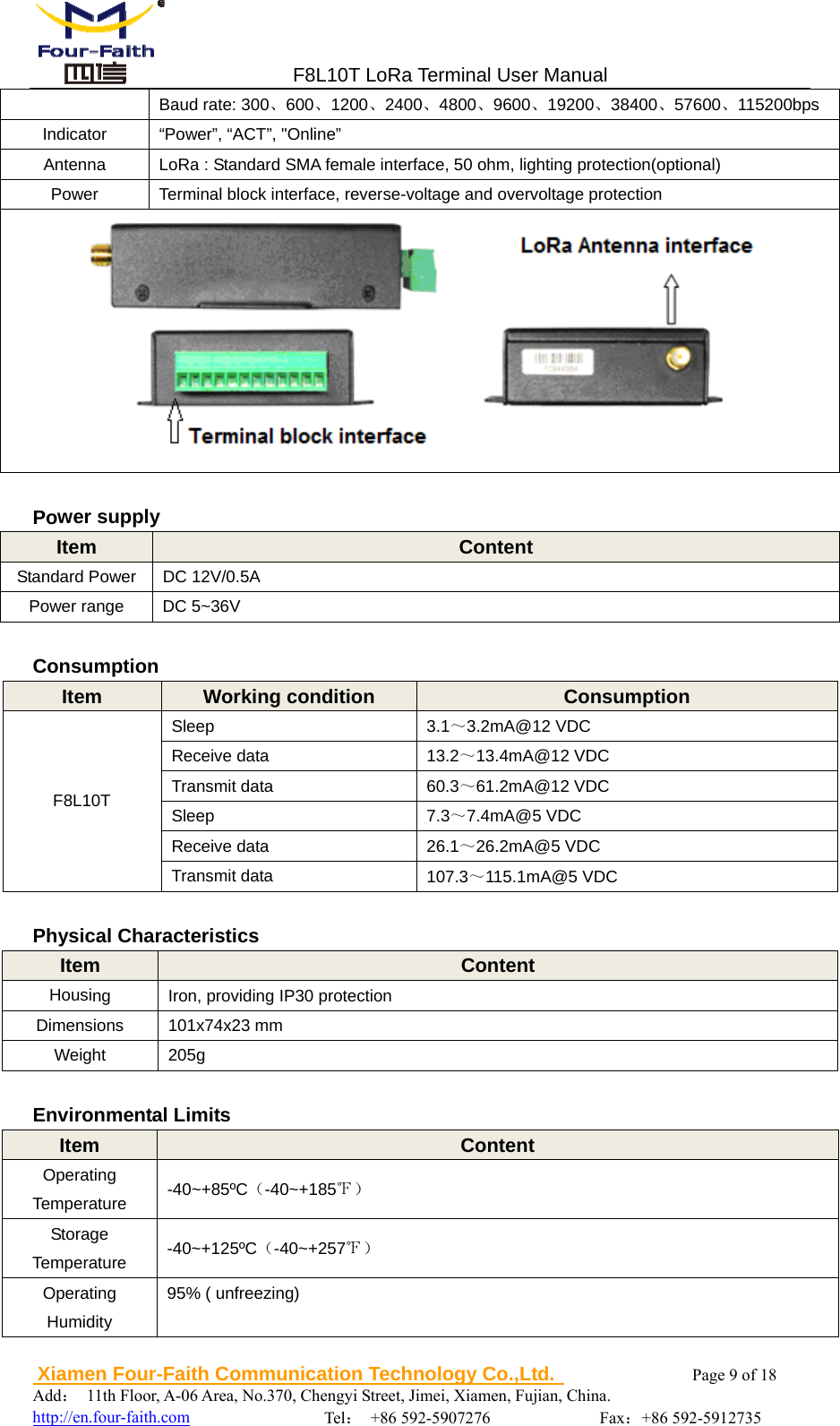
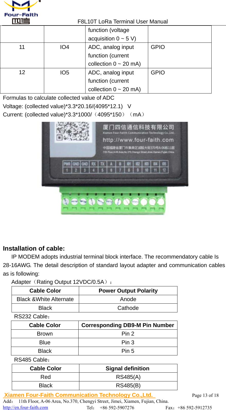
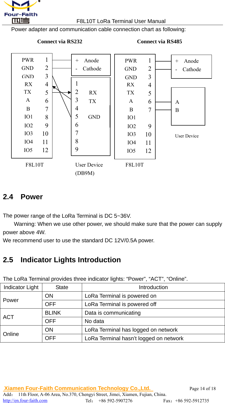
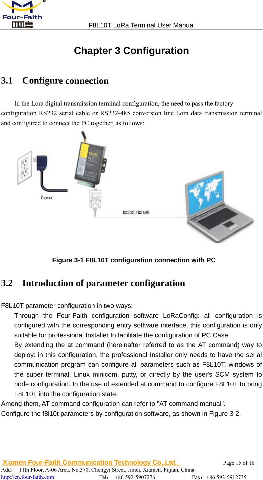
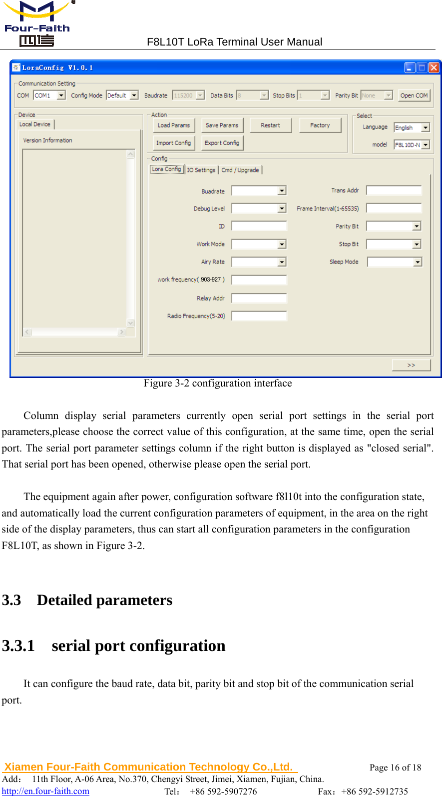
Xiamen Four-Faith Communication Technology Co., Ltd. F8L10T LoRa Terminal

User Manual

                                                                  F8L10T LoRa Terminal User Manual Document  Version  Page V1.1.2  Product Name:F8L10T  Total:18  F8L10T LoRa Terminal   User Manual        Xiamen Four-Faith Communication Technology Co., Ltd. Add:11th Floor, A-06 Area, No.370, Chengyi Street, Jimei, Xiamen, Fujian, China. Tel:+86 592-5907276 Fax:+86  592-5912735                   Web:en.four-faith.com
                                F8L10T LoRa Terminal User Manual  Xiamen Four-Faith Communication Technology Co.,Ltd.              Page 2 of 18     Add: 11th Floor, A-06 Area, No.370, Chengyi Street, Jimei, Xiamen, Fujian, China.                                    http://en.four-faith.com                Tel: +86 592-5907276             Fax:+86 592-5912735 Files Revised Record Date  Version  Remark  Author 2016-12-19 V1.0.0  Initial version  WSP 2017-02-20 V1.1.0 According to the product line , modify the radio frequency description. Adjust the parameter configuration   section with multiple details. ZDD 2017-08-17 V1.1.1 Add Formulas to calculate collected   value of ADC  YSL 2017-11-09 V1.1.2 Add Fcc Warning Add Working Principle Modify Communication Frequency Band Modify TX Power Modify F8L10T transmit data YSL
                                F8L10T LoRa Terminal User Manual  Xiamen Four-Faith Communication Technology Co.,Ltd.              Page 3 of 18     Add: 11th Floor, A-06 Area, No.370, Chengyi Street, Jimei, Xiamen, Fujian, China.                                    http://en.four-faith.com                Tel: +86 592-5907276             Fax:+86 592-5912735  Copyright Notice All contents in the files are protected by copyright law, and all copyrights are reserved by Xiamen Four-Faith Communication Technology Co., Ltd.Without written permission, all commercial use of the files from Four-Faith are forbidden, such as copy, distribute, reproduce the files, etc., but non-commercial purpose, downloaded or printed by individual   (all files shall be not revised, and the copyright and other proprietorship notice shall be   reserved) are welcome.   Trademark Notice Four-Faith、四信、 、 、 are all registered trademarks of Xiamen Four-Faith Communication Technology Co., Ltd., illegal use of the name of Four-Faith, trademarks and other marks of Four-Faith is forbidden, unless written permission is authorized in advance.
                                F8L10T LoRa Terminal User Manual  Xiamen Four-Faith Communication Technology Co.,Ltd.              Page 4 of 18     Add: 11th Floor, A-06 Area, No.370, Chengyi Street, Jimei, Xiamen, Fujian, China.                                    http://en.four-faith.com                Tel: +86 592-5907276             Fax:+86 592-5912735
                                F8L10T LoRa Terminal User Manual  Xiamen Four-Faith Communication Technology Co.,Ltd.              Page 5 of 18     Add: 11th Floor, A-06 Area, No.370, Chengyi Street, Jimei, Xiamen, Fujian, China.                                    http://en.four-faith.com                Tel: +86 592-5907276             Fax:+86 592-5912735   FCC WARNING Any Changes or modifications not expressly approved by the party responsible for compliance could void the user's authority to operate the equipment. This device complies with part 15 of the FCC Rules. Operation is subject to the following two conditions: (1) This device may not cause harmful interference, and (2) this device must accept any interference received, including interference that may cause undesired operation. Note: This equipment has been tested and found to comply with the limits for a Class B digital device, pursuant to part 15 of the FCC Rules. These limits are designed to provide reasonable protection against harmful interference in a residential installation. This equipment generates, uses and can radiate radio frequency energy and, if not installed   and used in accordance with the instructions, may cause harmful interference to radio communications. However, there is no guarantee that interference will not occur in a particular installation. If this equipment does cause harmful interference to radio or television reception, which can be determined by turning the equipment off and on, the user is encouraged to try to correct the interference by one or more of the following measures:  —Reorient or relocate the receiving antenna.  —Increase the separation between the equipment and receiver.  —Connect the equipment into an outlet on a circuit different from that to which the receiver is connected.  —Consult the dealer or an experienced radio/TV technician for help. This product needs a professional installation. The installer must be trained by our company. Installer must follow the instructions to install.
                                F8L10T LoRa Terminal User Manual  Xiamen Four-Faith Communication Technology Co.,Ltd.              Page 6 of 18     Add: 11th Floor, A-06 Area, No.370, Chengyi Street, Jimei, Xiamen, Fujian, China.                                    http://en.four-faith.com                Tel: +86 592-5907276             Fax:+86 592-5912735 CCoonntteennttss  Chapter 1 Brief Introduction of Product ....................................................................................... 7  1.1  General ............................................................................................................................. 7  1.2  Features and Benefits ....................................................................................................... 7  1.4  Specifications ................................................................................................................... 8  Chapter 2 Installation Introduction ............................................................................................. 10  2.1  General ........................................................................................................................... 10  2.2  Encasement List ............................................................................................................. 10  2.3  Installation and Cable Connection ................................................................................. 10 2.4  Power ............................................................................................................................. 14  2.5  Indicator Lights Introduction ......................................................................................... 14 Chapter 3 Configuration .............................................................................................................. 15 3.1  Configure connection ..................................................................................................... 15  3.2  Introduction of parameter configuration ........................................................................ 15 3.3  Detailed parameters ........................................................................................................ 16  3.3.1  serial port configuration ...................................................................................... 16 3.3.2  serial port work mode .......................................................................................... 17 3.3.3  ID ........................................................................................................................ 17  3.3.4  working frequency .............................................................................................. 17 3.3.5  Relay address ...................................................................................................... 17 3.3.6  sleep mode ......................................................................................................... 177 3.3.7  Debug level ......................................................................................................... 18
                                F8L10T LoRa Terminal User Manual  Xiamen Four-Faith Communication Technology Co.,Ltd.              Page 7 of 18     Add: 11th Floor, A-06 Area, No.370, Chengyi Street, Jimei, Xiamen, Fujian, China.                                  http://en.four-faith.com                Tel: +86 592-5907276             Fax:+86 592-5912735 Chapter 1 Brief Introduction of Product 1.1  General F8L10T LoRa data transmission terminal is a wireless data transmission terminal based on LoRa spread spectrum technology. At the same time using Lora wireless transmission technology for short distance data transmission. This product adopts industrial grade Lora scheme with high performance, based on embedded real-time operating system as the software platform, while providing RS232 and RS485 (or RS422) interface, can be directly connected to the serial device, realize the transparent data transmission function; low power design, lowest power consumption is less than 5ma@ 12VDC; 5 I/O, can achieve the digital input output, analog input, pulse counting function. It has been widely used on M2M fields, such as electric power, intelligent trafic, wireless   metering, industrial automation, telemetry, water supply, environment protection, weather, and so on.  1.2  Features and Benefits Design for Industrial Application   High-powered industrial LoRa chip and MCU   High-powered industrial 32 bits CPU   Support low power consumption mode, including multi-sleep and trigger modes to reduce the power dissipation farthest   Housing: iron, providing IP30 protection   Power range: DC 5~36V Stability and Reliability   Support hardware and software WDT   RS232/RS485/RS422 port: 15KV ESD protection   Power port: reverse-voltage and overvoltage protection   Antenna port: lightning protection(optional) Standard and Convenience   Adopt terminal block interface, convenient for industrial application   Support standard RS232 and RS485(or RS422) port that can connect to serial devices directly   TTL logic level RS232 interface can be customized, ADC interface can be customized   Support intellectual mode, enter into communication state automatically when powered   Provide management software for remote management
                                F8L10T LoRa Terminal User Manual  Xiamen Four-Faith Communication Technology Co.,Ltd.              Page 8 of 18     Add: 11th Floor, A-06 Area, No.370, Chengyi Street, Jimei, Xiamen, Fujian, China.                                  http://en.four-faith.com                Tel: +86 592-5907276             Fax:+86 592-5912735  Support several work modes   Convenient configuration and maintenance interface High-performance   Support Lora wireless short-range data transmission capabilities, with self-organizing network capabilities   Relay routing and terminal device functionality   Network capacity: 65000 nodes (typical number of 300)   Send mode flexible: Broadcast send or destination address send mode optional   Supply 5 I/O channels, can achieve the analog input of the 3 channels, the digital input and output of the 2 channels; compatible with the pulse count function of the 2 channels 1.3 Specifications LoRa Specification Item  Content Module  Industrial LoRa module Communication Frequency Band The product family supports a wide range of frequency bands   ISM: 903-927MHz Indoor/Urban Communication Distance F8L10T:1km          Outdoor/Visual Communication Distance F8L10T:3.5km     Rate 6 level adjustable(0.3、0.6、1.0、1.8、3.1、5.5Kbps) TX Power  903-927 MHz:92.91dBuV/m@3m RX Sensitivity  -140dBm Channel Number  25  Hardware System Item  Content CPU  Industrial 32bits CPU FLASH 128KB RAM 16KB  Interface type Item  Content Serial 1 RS232 port and 1 RS485(orRS422) port, 15KV ESD protection Data bits: 8 Stop bits: 1, 2 Parity: none, even, odd, space, mark
                                F8L10T LoRa Terminal User Manual  Xiamen Four-Faith Communication Technology Co.,Ltd.              Page 9 of 18     Add: 11th Floor, A-06 Area, No.370, Chengyi Street, Jimei, Xiamen, Fujian, China.                                  http://en.four-faith.com                Tel: +86 592-5907276             Fax:+86 592-5912735 Baud rate: 300、600、1200、2400、4800、9600、19200、38400、57600、115200bps Indicator  “Power”, “ACT”, "Online” Antenna  LoRa : Standard SMA female interface, 50 ohm, lighting protection(optional) Power  Terminal block interface, reverse-voltage and overvoltage protection   Power supply Item  Content Standard Power  DC 12V/0.5A Power range  DC 5~36V  Consumption Item  Working condition  Consumption F8L10T Sleep  3.1~3.2mA@12 VDC Receive data  13.2~13.4mA@12 VDC Transmit data  60.3~61.2mA@12 VDC Sleep  7.3~7.4mA@5 VDC Receive data  26.1~26.2mA@5 VDC Transmit data  107.3~115.1mA@5 VDC  Physical Characteristics Item  Content Housing  Iron, providing IP30 protection Dimensions 101x74x23 mm Weight 205g  Environmental Limits Item  Content Operating Temperature  -40~+85ºC(-40~+185℉) Storage Temperature  -40~+125ºC(-40~+257℉) Operating Humidity 95% ( unfreezing)
                                F8L10T LoRa Terminal User Manual  Xiamen Four-Faith Communication Technology Co.,Ltd.              Page 10 of 18     Add: 11th Floor, A-06 Area, No.370, Chengyi Street, Jimei, Xiamen, Fujian, China.                                  http://en.four-faith.com                Tel: +86 592-5907276             Fax:+86 592-5912735 Chapter 2 Installation Introduction 2.1  General The LoRa Terminal must be installed correctly by professional Installer to make it work properly. Warning: 1.Forbid to install the MODEM when powered! 2.This device will not be sold to the general public,it will be sold to dealers only. 3.This device requires controlled installation location by professional installers. 4.This device requires prfessional configuration for use.         5.Be sure to install the original antenna, the installation of other antenna, it will cause disputes, need to bear the relevant legal responsibility. 2.2  Encasement List Name Quantity RemarkLoRa Terminal host  1   LoRa Antenna  1   Power adapter  1   RS232 data cable  1  optionalRS485 data cable  1  optionalManual CD  1   Certification card  1   Maintenance card  1   2.3    Installation and Cable Connection Dimension: (unit: mm)
5923                                F8L10T LoRa Terminal User Manual  Xiamen Four-Faith Communication Technology Co.,Ltd.              Page 11 of 18     Add: 11th Floor, A-06 Area, No.370, Chengyi Street, Jimei, Xiamen, Fujian, China.                                  http://en.four-faith.com                Tel: +86 592-5907276             Fax:+86 592-5912735 352828825Ф3Ф54  Installation of antenna: Screw the SMA male pin of the LoRa antenna to the female SMA interface of the Device with sign  “LoRa”. Warning: The cellular antenna and the LoRa antenna can not be connected wrongly. And the antennas must be screwed tightly, or the signal quality of antenna will be   influenced! Antenna Installation Instructions: 1, Install the antenna far away from the large area metal and ground. 2, Keep the antennas visual. 3, Minimize obstructions between the antennas.     4, Antenna extension line try to straighten, sucker base to be adsorbed on the metal object. The performance of different antenna installation types, as the figure 2-2.
                                F8L10T LoRa Terminal User Manual  Xiamen Four-Faith Communication Technology Co.,Ltd.              Page 12 of 18     Add: 11th Floor, A-06 Area, No.370, Chengyi Street, Jimei, Xiamen, Fujian, China.                                  http://en.four-faith.com                Tel: +86 592-5907276             Fax:+86 592-5912735  Figure 2-2 Installation antenna mode User Interface Signal Definition Pin NumberSignal NameDefault FunctionExtensible Function1 PWR Power input anode N/A 2 GND Power Ground N/A 3 GND Power Ground N/A 4 RX RS232 RX N/A 5 TX RS232 TX N/A 6 A RS485 anode N/A 7 B RS485 cathode N/A 8 IO1 GPIO  sleep control 9 IO2 GPIO  N/A 10  IO3  ADC, analog input  GPIO
                                F8L10T LoRa Terminal User Manual  Xiamen Four-Faith Communication Technology Co.,Ltd.              Page 13 of 18     Add: 11th Floor, A-06 Area, No.370, Chengyi Street, Jimei, Xiamen, Fujian, China.                                  http://en.four-faith.com                Tel: +86 592-5907276             Fax:+86 592-5912735 function (voltage acquisition 0 ~ 5 V) 11  IO4  ADC, analog input function (current collection 0 ~ 20 mA) GPIO 12  IO5  ADC, analog input function (current collection 0 ~ 20 mA) GPIO Formulas to calculate collected value of ADC Voltage: (collected value)*3.3*20.16/(4095*12.1)   V Current: (collected value)*3.3*1000/(4095*150)(mA)     Installation of cable: IP MODEM adopts industrial terminal block interface. The recommendatory cable Is 28-16AWG. The detail description of standard layout adapter and communication cables as is following: Adapter(Rating Output 12VDC/0.5A): Cable Color  Power Output Polarity Black &White Alternate  Anode Black Cathode RS232 Cable: Cable Color  Corresponding DB9-M Pin NumberBrown Pin 2 Blue Pin 3 Black Pin 5 RS485 Cable: Cable Color  Signal definition  Red RS485(A) Black RS485(B)
                                F8L10T LoRa Terminal User Manual  Xiamen Four-Faith Communication Technology Co.,Ltd.              Page 14 of 18     Add: 11th Floor, A-06 Area, No.370, Chengyi Street, Jimei, Xiamen, Fujian, China.                                  http://en.four-faith.com                Tel: +86 592-5907276             Fax:+86 592-5912735 Power adapter and communication cable connection chart as following:  2.4  Power The power range of the LoRa Terminal is DC 5~36V. Warning: When we use other power, we should make sure that the power can supply power above 4W. We recommend user to use the standard DC 12V/0.5A power. 2.5  Indicator Lights Introduction The LoRa Terminal provides three indicator lights: “Power”, “ACT”, “Online”. Indicator Light  State  Introduction Power  ON  LoRa Terminal is powered on OFF  LoRa Terminal is powered off ACT  BLINK Data is communicating OFF No data Online  ON  LoRa Terminal has logged on network OFF  LoRa Terminal hasn’t logged on network F8L10T  F8L10T  User Device (DB9M) User Device 123456789101112RX GND TX A B IO1 IO2 IO3 IO4 PWR GND IO5 1 2 3 4 5 6 7 8 9 GND TX RX + Anode - Cathode RX 12345678 9101112RX GND TX A B IO1 IO2 IO3 IO4 PWR GND IO5 + Anode - Cathode  A B Connect via RS232  Connect via RS485
                                F8L10T LoRa Terminal User Manual  Xiamen Four-Faith Communication Technology Co.,Ltd.              Page 15 of 18     Add: 11th Floor, A-06 Area, No.370, Chengyi Street, Jimei, Xiamen, Fujian, China.                                  http://en.four-faith.com                Tel: +86 592-5907276             Fax:+86 592-5912735 Chapter 3 Configuration 3.1  Configure connection In the Lora digital transmission terminal configuration, the need to pass the factory configuration RS232 serial cable or RS232-485 conversion line Lora data transmission terminal and configured to connect the PC together, as follows:   Figure 3-1 F8L10T configuration connection with PC 3.2    Introduction of parameter configuration F8L10T parameter configuration in two ways: Through the Four-Faith configuration software LoRaConfig: all configuration is configured with the corresponding entry software interface, this configuration is only suitable for professional Installer to facilitate the configuration of PC Case. By extending the at command (hereinafter referred to as the AT command) way to deploy: in this configuration, the professional Installer only needs to have the serial communication program can configure all parameters such as F8L10T, windows of the super terminal, Linux minicom, putty, or directly by the user's SCM system to node configuration. In the use of extended at command to configure F8L10T to bring F8L10T into the configuration state. Among them, AT command configuration can refer to "AT command manual". Configure the f8l10t parameters by configuration software, as shown in Figure 3-2.
                                F8L10T LoRa Terminal User Manual  Xiamen Four-Faith Communication Technology Co.,Ltd.              Page 16 of 18     Add: 11th Floor, A-06 Area, No.370, Chengyi Street, Jimei, Xiamen, Fujian, China.                                  http://en.four-faith.com                Tel: +86 592-5907276             Fax:+86 592-5912735  Figure 3-2 configuration interface  Column display serial parameters currently open serial port settings in the serial port parameters,please choose the correct value of this configuration, at the same time, open the serial port. The serial port parameter settings column if the right button is displayed as "closed serial". That serial port has been opened, otherwise please open the serial port.    The equipment again after power, configuration software f8l10t into the configuration state, and automatically load the current configuration parameters of equipment, in the area on the right side of the display parameters, thus can start all configuration parameters in the configuration F8L10T, as shown in Figure 3-2.  3.3  Detailed parameters 3.3.1  serial port configuration It can configure the baud rate, data bit, parity bit and stop bit of the communication serial port. 903-927
                                F8L10T LoRa Terminal User Manual  Xiamen Four-Faith Communication Technology Co.,Ltd.              Page 17 of 18    Add:  11th Floor, A-06 Area, No.370, Chengyi Street, Jimei, Xiamen, Fujian, China.                                  http://en.four-faith.com                Tel: +86 592-5907276             Fax:+86 592-5912735 3.3.2  serial port work mode Module serial data work can be divided into "TRNS","AT" and "API". "TRNS": data transmission, when the need to pass through the address configuration, namely the destination address.   "AT": protocol format reference "Lora AT commands manual",usually used for parameter configuration and manual testing. "API": serial data must be based on a certain data format for sending and receiving, protocol format reference "Lora API commands manual". The maximum length is 100 bytes. Default: TRNS 3.3.3  ID Set the module ID, configurable range 0~65535. 3.3.4  working frequency Module data transmission frequency, different hardware modules can work different   frequency bands,Typical operating frequency band is 903-927 MHz, 1000 kHz spacing for a channel. Different application areas have different frequency band restrictions, as well as different channel interference factors, the error rate is different, so need to adjust the value according to the actual situation. The default value is 903. 3.3.5  Relay address When the transmission distance between nodes is too far, this parameter is set to the relay node’ ID, and the relay node will help the node forward the data to the final destination node. Default: 1000  3.3.6  sleep mode When the device is in low power mode, can be set to NONE(not dormant), TIME(timing   dormant) and DEEP(deep sleep). Regular sleep, you need to configure the "wake up time"and   "sleep time"; the depth of dormancy, only through the IO1 pin to wake up. Default: NONE  In regular sleep, keep the device wake-up time, unit MS, when the device wake up super this time will go to sleep.
                                F8L10T LoRa Terminal User Manual  Xiamen Four-Faith Communication Technology Co.,Ltd.              Page 18 of 18     Add:  11th Floor, A-06 Area, No.370, Chengyi Street, Jimei, Xiamen, Fujian, China.                                  http://en.four-faith.com                Tel: +86 592-5907276             Fax:+86 592-5912735 In regular sleep, keep the device dormant time, unit MS, when the device sleep over this time will wake up, in a normal working state. 3.3.7  Debug level Debug level control module log display, can be divided into three debugging levels, which: 0 do not output any log information   1 output Key log information   2 output detailed log information Default: 1

Navigation menu