Xiamen Keytop Comm and Tech KEY-WB02 Wireless Led Indicator User Manual
Xiamen Keytop Comm.&Tech.Co.;,Ltd Wireless Led Indicator
User Manual

Wireless Parking
Guidance System Manual
The China brand enterprise of top-selling parking guidance systems
KEYTOP Parking INC.

KEYTOP
KEYTOP Parking
Parking INC .
IN C.
Addr:Unit 301,No.58 GuanRi RD.,software Park,XiaMen,China
P.C:361008
TEL.:86-592-3521117
Fax:86-592-2611689
Web.:www.ikeytop.com
Email:zqb @keytop.com.cn
- 1 -
Catalogue
1 Principle of Wireless Parking Guidance System............................................................ - 2 -
2 Diagram of Wireless Parking Guidance System.............................................................- 2 -
3 Devices Instructions........................................................................................................- 3 -
3.1 Central Control Unit(CCU)................................................................................................ - 3 -
3.1.1 Parameters of CCU................................................................................................... - 3 -
3.1.2 Introduction of CCU Port......................................................................................... - 3 -
3.1.3 Configuration of CCU.............................................................................................. - 4 -
3.2 Wireless Detector ZCU....................................................................................................... - 4 -
3.2.1 Parameters of Wireless ZCU.....................................................................................- 4 -
3.2.2 Introduction of ZCU Control Panel.......................................................................... - 5 -
3.2.3 Setting Instruction.....................................................................................................- 6 -
3.2.4 Installation of Wireless Detector ZCU....................................................................- 10 -
3.3 Wireless Display ZCU...................................................................................................... - 10 -
3.3.1 Parameters of Wireless Display ZCU..................................................................... - 10 -
3.3.2 Address Setting of Wireless Display ZCU..............................................................- 11 -
3.3.3 Setting Instruction...................................................................................................- 12 -
3.3.4 Installation of Wireless Display ZCU..................................................................... - 13 -
3.4 Wireless Ultrasonic Detector............................................................................................ - 14 -
3.4.1 Appearance of Wireless Ultrasonic Detector..........................................................- 14 -
3.4.2 Parameters of Wireless Ultrasonic Detector........................................................... - 14 -
3.4.3 Address and Detecting Distance of Wireless Ultrasonic Detector..........................- 15 -
3.4.4 Settings of Nodes Under Ultrasonic Detectors....................................................... - 16 -
3.4.5 Address Settings of Detectors(Address showed on ZCU)......................................- 16 -
3.4.6 Installation of Wireless Ultrasonic Detector........................................................... - 16 -
3.5 Wireless LED Indicator.....................................................................................................- 19 -
3.5.1 Parameters of Wireless LED Indicator................................................................... - 19 -
3.5.2 Address Setting of LED Indicator........................................................................- 20 -
3.6 Wireless LED Display.......................................................................................................- 20 -
3.6.1 Parameters of Wireless LED Display..................................................................... - 21 -
3.6.2 Address Setting of Wireless Transmitting Module................................................. - 21 -
3.6.3 Address Setting of LED Display Controller Card.................................................. - 21 -
Addendum 1-1 Ultrasonic Detector Address Settings................................................................... - 23 -
KEYTOP
KEYTOP Parking
Parking INC .
IN C.
Addr:Unit 301,No.58 GuanRi RD.,software Park,XiaMen,China
P.C:361008
TEL.:86-592-3521117
Fax:86-592-2611689
Web.:www.ikeytop.com
Email:zqb @keytop.com.cn
- 2 -
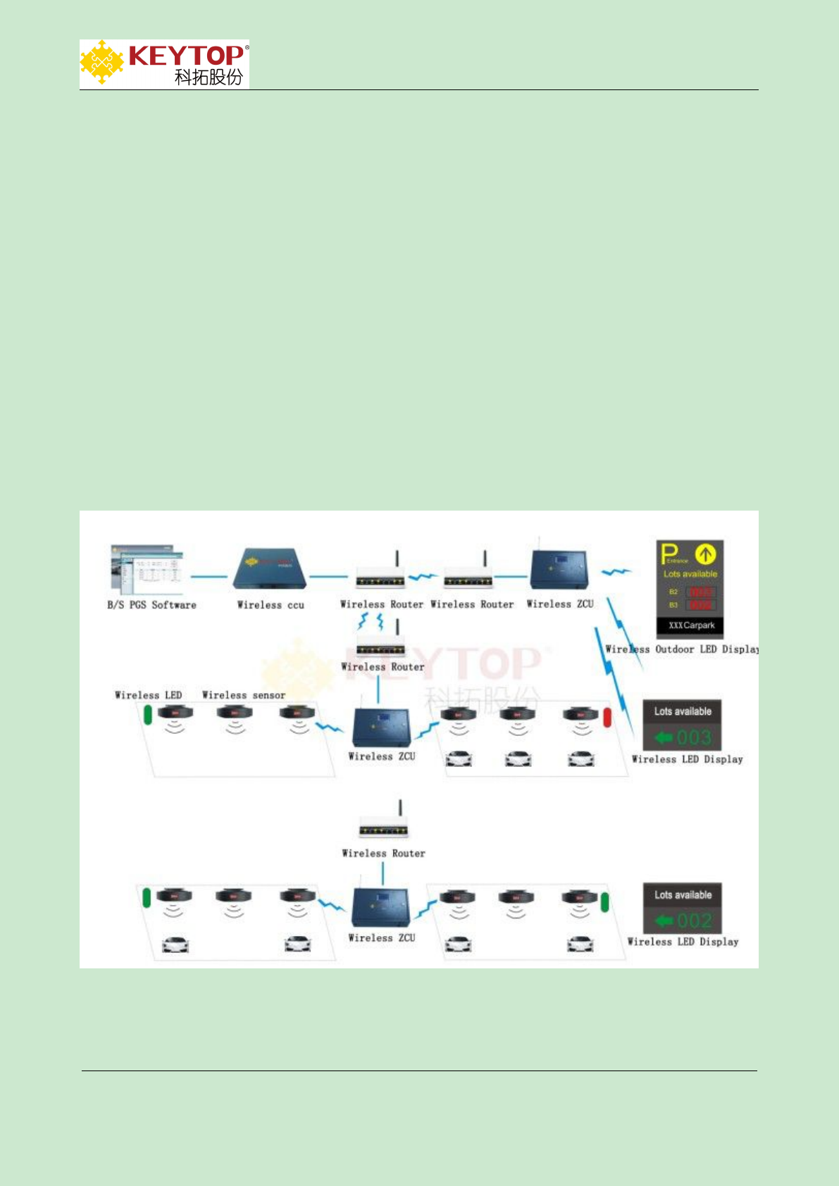
1 Principle of Wireless Parking Guidance System
Wireless ultrasonic detector detects the status of parking lot,then sends real-time parking lot
information to the corresponding wireless detector ZCUs by wireless RF signal.Through
WIFI ,wireless ZCU sends the collected parking information to wireless routers connected to
CCU.After collecting information of the whole carport,CCU updates parking lot data in
time.Wireless routers sends these data to corresponding LED displays by LED display ZCU.In this
way,wireless parking guidance system realizes the function of guiding vehicles to empty parking
spaces.
Remark:it's better to use separated ZCU for the led display to ensure the system's working
stabilities,so the system has detector ZCU and display ZCU.
2 Diagram of Wireless Parking Guidance System
KEYTOP
KEYTOP Parking
Parking INC .
IN C.
Addr:Unit 301,No.58 GuanRi RD.,software Park,XiaMen,China
P.C:361008
TEL.:86-592-3521117
Fax:86-592-2611689
Web.:www.ikeytop.com
Email:zqb @keytop.com.cn
- 3 -
3 Devices Instructions
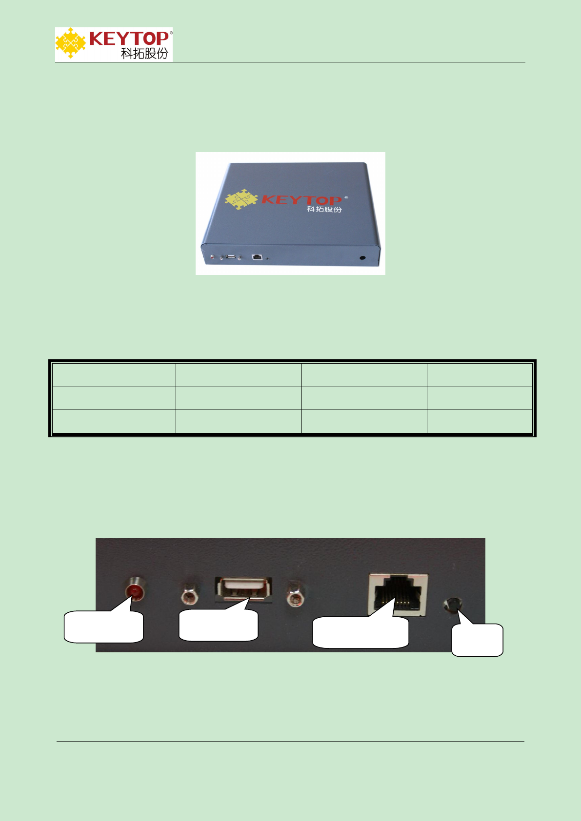
3.1 Central Control Unit(CCU)
3.1.1 Parameters of CCU
3.1.2 Introduction of CCU Port
USB upgrade port:insert upgrading U disk to USB port,get power on to CCU,then CCU
procedure will upgrade automatically.
Wireless router port:CCU is connected to wireless router.To visit CCU by computer,please
supply voltage:
110V/220V AC
working voltage:
5VDC
power dissipation:
5.8W
communication way:
TCP/IP
operating system:
WINDOWS XP-E
size:
28.5*22*5CM
power
indicator
USB upgrade
port
wireless router
port
reset
button
KEYTOP
KEYTOP Parking
Parking INC .
IN C.
Addr:Unit 301,No.58 GuanRi RD.,software Park,XiaMen,China
P.C:361008
TEL.:86-592-3521117
Fax:86-592-2611689
Web.:www.ikeytop.com
Email:zqb @keytop.com.cn
- 4 -
link network cable to wireless router’s LAN port.When only one node controller is connected
and communication distance less than 100 meters,wireless router port can directly
communicate to CCU port.
3.1.3 Configuration of CCU
To make LED display show correct information,it needs to configurate the CCU.Otherwise,LED
display will only show initial content of powering-on(000+arrow).
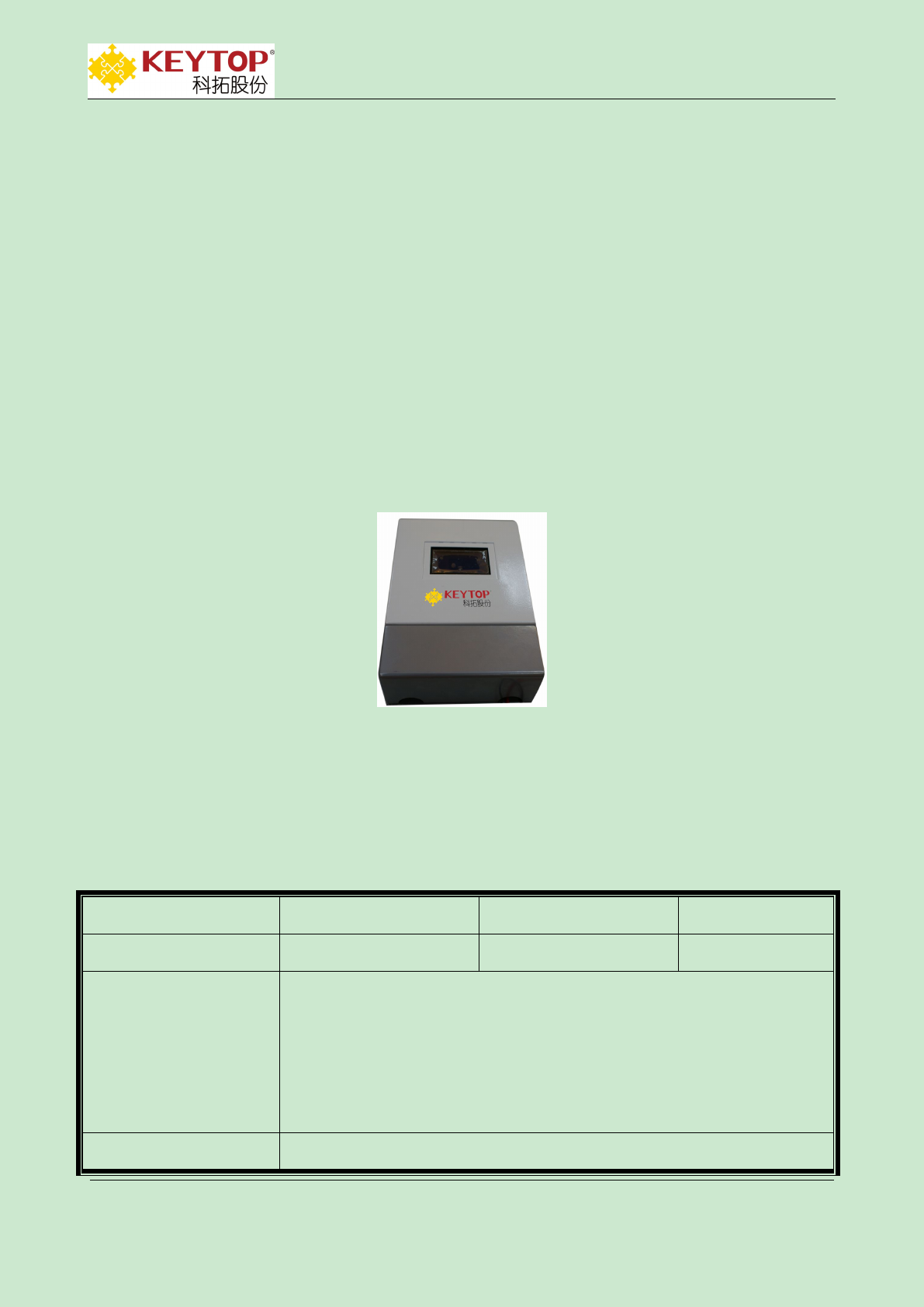
3.2 Wireless Detector ZCU
3.2.1 Parameters of Wireless ZCU
supply voltage:
110V/220V AC
working voltage:
5V DC
power dissipation:
3W
working temperature:
-40~80℃
communication way:
1.communicate with wireless detector by 915MHz,transmitting
power:0dBm,covering range:30m radius. Can be linked with 120
detector at most.
2.communicate with CCU by TCP/IP,can be linked by network cable or
WIFI.
size:
265mm*180mm*70mm(length*width*height)
KEYTOP
KEYTOP Parking
Parking INC .
IN C.
Addr:Unit 301,No.58 GuanRi RD.,software Park,XiaMen,China
P.C:361008
TEL.:86-592-3521117
Fax:86-592-2611689
Web.:www.ikeytop.com
Email:zqb @keytop.com.cn
- 5 -
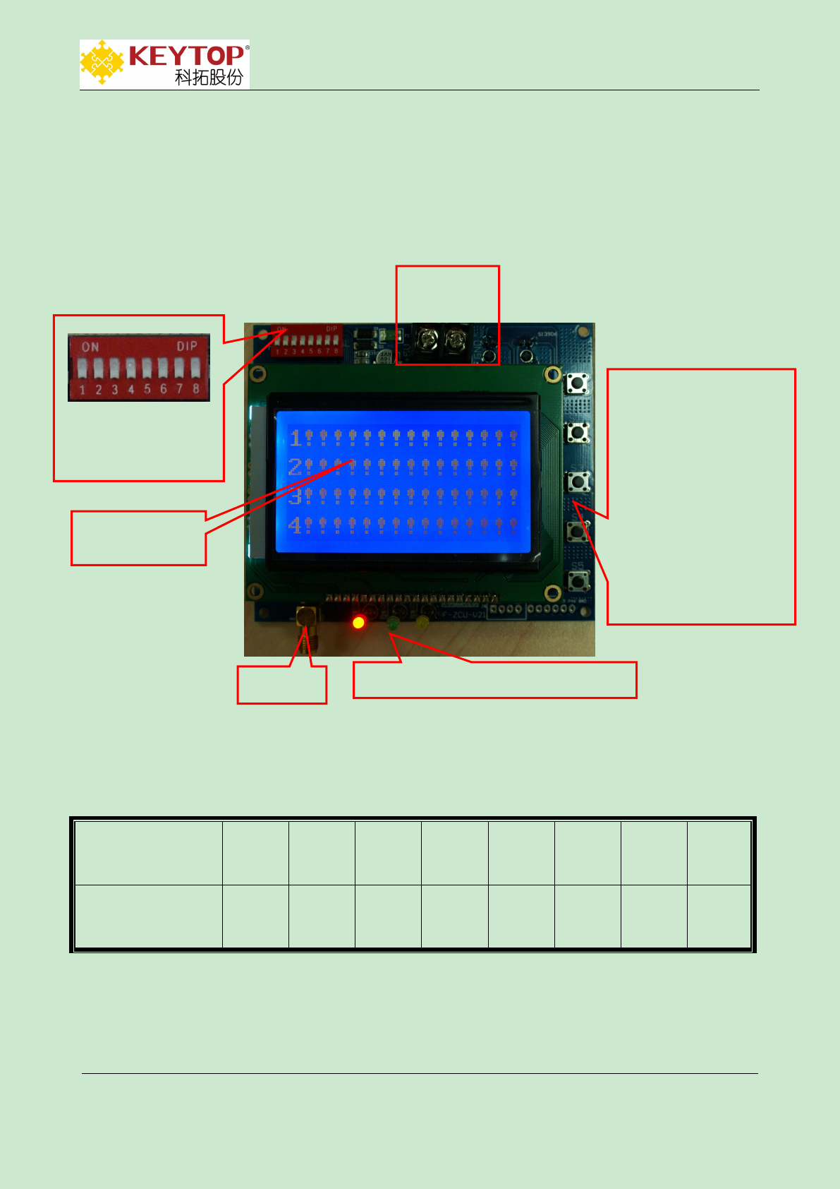
3.2.2 Introduction of ZCU Control Panel
ZCU Control Panel
DIP Switch(total 8 jumpers,1 is high,8 is low)
Switch digits
(pic.b)
1
2
3
4
5
6
7
8
Switch value
(ON-effective)
128
64
32
16
8
4
2
1
For example,set ZCU address 5.
5=4+1,set serial No. 6 and No.8 to ON,address setting finished,ZCU address will be 5 after
repowering on.
Buttons:
S1 pages switch
S2 add
S3 minus
S4 options switch
S5 setting
power
supply port
+5V GND
DIP switch
1 is high position,8 is low
position.
NO means 1,OFF means
0
indicator lights:red,green,yellow
aerial
LCD display

KEYTOP
KEYTOP Parking
Parking INC .
IN C.
Addr:Unit 301,No.58 GuanRi RD.,software Park,XiaMen,China
P.C:361008
TEL.:86-592-3521117
Fax:86-592-2611689
Web.:www.ikeytop.com
Email:zqb @keytop.com.cn
- 6 -
supply power port:VCC---+5V;GND---ground;
LED indicator:
red:power supply lamp;
green:detector’s communication lamp,when detector sends data to detector ZCU,the
green lamp will flash.
yellow :CCU communication lamp.The lamp doesn’t light up when failing to connect
CCU.In the process of connecting CCU,lamp will flash one time each 2 seconds.The lamp
stays lighting up when successfully linked to CCU.When CCU sends data to ZCU,yellow
lamp will flash quickly.
Buttons’ functions:
ZCU has 5 buttons,from up to down is:
(S1)pages switch button,(S2)add button,(S3)minus button,(S4)options switch
button,(S5)setting button
S1-pages switch button:In non-setting condition,press this button can switch pages of
different parking status.In setting condition,press this button to enter submenu of
cursor“<”.
S2-add button :In non-setting condition,press this button can inquire network port’s
configuration.In setting condition,press this button to act PLUS operation of corresponding
numbers of cursor.
S3-minus button :In setting condition,press this button to act MINUS operation of
corresponding numbers of cursor.
S4-options switch button:In setting condition,long press this button can swift cursor to
different setting options.
S5-setting button:In non-setting condition,long press this button until yellow lamp and
green lamp flash 3 times at the same time,it means entering the setting condition.In setting
process,press this button can go back to main setting menu.After setting,long press this
button until yellow and green lamps flash 3 times at the same time,which means exiting
setting condition.
3.2.3 Setting Instruction
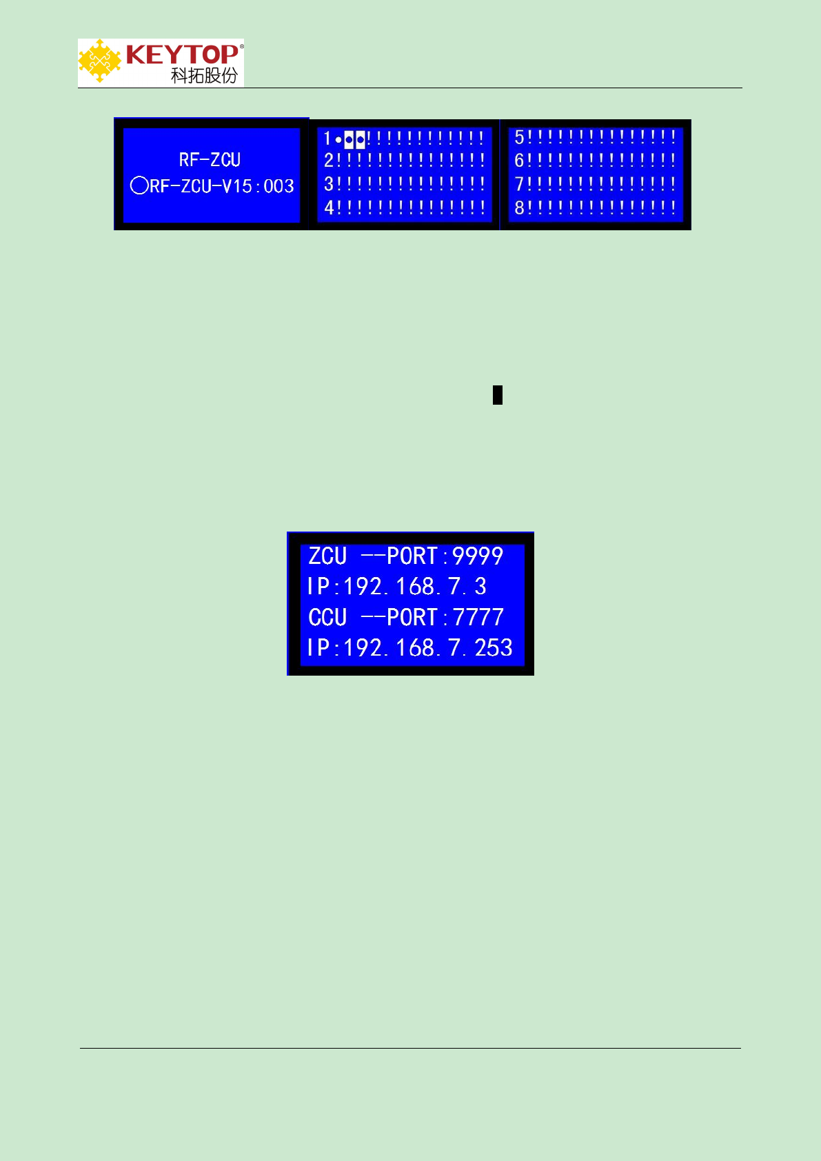
1.When powering on,press button S1 can switch 3 interfaces as showed in Pic.1-2:
KEYTOP
KEYTOP Parking
Parking INC .
IN C.
Addr:Unit 301,No.58 GuanRi RD.,software Park,XiaMen,China
P.C:361008
TEL.:86-592-3521117
Fax:86-592-2611689
Web.:www.ikeytop.com
Email:zqb @keytop.com.cn
- 7 -
(a)device version&address (b)1~60 detector’s status (c) 61~120 detector’s status
Pic. 1-2
(a)"Detector ZCU"means name of device,"RF-ZCU-V04"means version of
software,"003"means the address of detector ZCU is 3;(b)(c)means the ZCU is connected with 3
detectors,"●" means parking space under address 1 is vacant,"●"means parking space under address
2、3 are occupied,addresses 4--120 "!" means non-exist or breakdown.
2. Press button S2:enter inquire interface of network port setting,as showed in Pic.1-3
Pic.1-3 network port setting
First line:ZCU--PORT:9999,means port No. of ZCU is 9999;
Second line:IP:192.168.7.3,means IP address of node is 192.168.7.3,IP address namely is
ZCU address and doesn’t need to be set up manually;
Third line:CCU--PORT:7777,means port No. Of CCU is 7777;
Fourth line:IP:192.168.7.253,means CCU address is 192.168.7.253;
3.Long press button S5: enter setting interface as showed in Pic.1-4
KEYTOP
KEYTOP Parking
Parking INC .
IN C.
Addr:Unit 301,No.58 GuanRi RD.,software Park,XiaMen,China
P.C:361008
TEL.:86-592-3521117
Fax:86-592-2611689
Web.:www.ikeytop.com
Email:zqb @keytop.com.cn
- 8 -
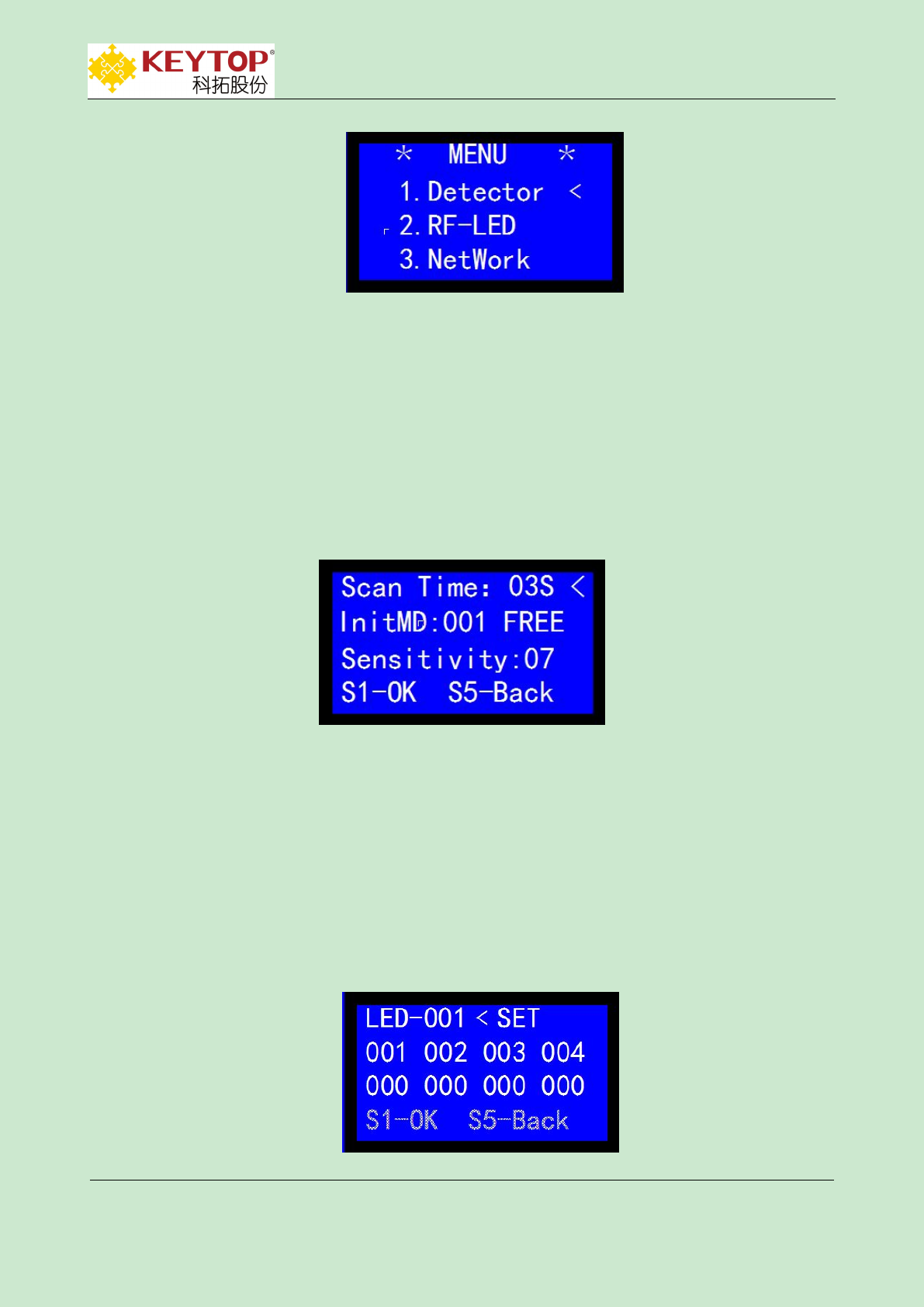
Pic.1-4 main menu
UD setting Set parameters of ultrasonic detector
LED indicator setting Set parameters of LED indicator
Network port setting Set parameters of network port
Press S4 to switch cursor “<”to options needed to be revised,then press S1 to enter
corresponding options.
Submenu setting of UD,as showed in Pic.1-5:
Pic.1-5 setting menu of UD
Scan time:set interval time for detector’s scanning,effective setting range is 03s~60s.
Press button S2 to add value,press button S3 to minus value,press S1 to send setting commands
of detector’s scan time(10 minutes needed for resending all detectors’ commands to ZCU),press
button S5 to go back previous menu.
Initialization/flexibility test/filter times:only available with wireless magnetic sensor
Submenu setting of LED indictor as showed in Pic.1-6
KEYTOP
KEYTOP Parking
Parking INC .
IN C.
Addr:Unit 301,No.58 GuanRi RD.,software Park,XiaMen,China
P.C:361008
TEL.:86-592-3521117
Fax:86-592-2611689
Web.:www.ikeytop.com
Email:zqb @keytop.com.cn
- 9 -
Pic.1-6 LED indicator VS Ultrasonic Detector
LED-000 SET choose the address of LED indictor ned to be set
000 000 000 000
000 000 000 000 one wireless LED indicator can set 8 detectors’ addresses at most
When UD detects parking spaces are all occupied,then wireless LED indicator will turn RED.
When UD detects more than 1 empty parking space,wireless LED indicator will turn
GREEN.
Press button S4 to switch options,button S2 to add values,single click will add 1 value,long
press S2 will instantly add values;press button S3 to minus value,single click minus 1 value,long
press will instantly minus values; after setting,press button S1 to send LED indicator’s setting
information,press S5 to go back previous menu.
Submenu setting of network port as showed in Pic.1-7:
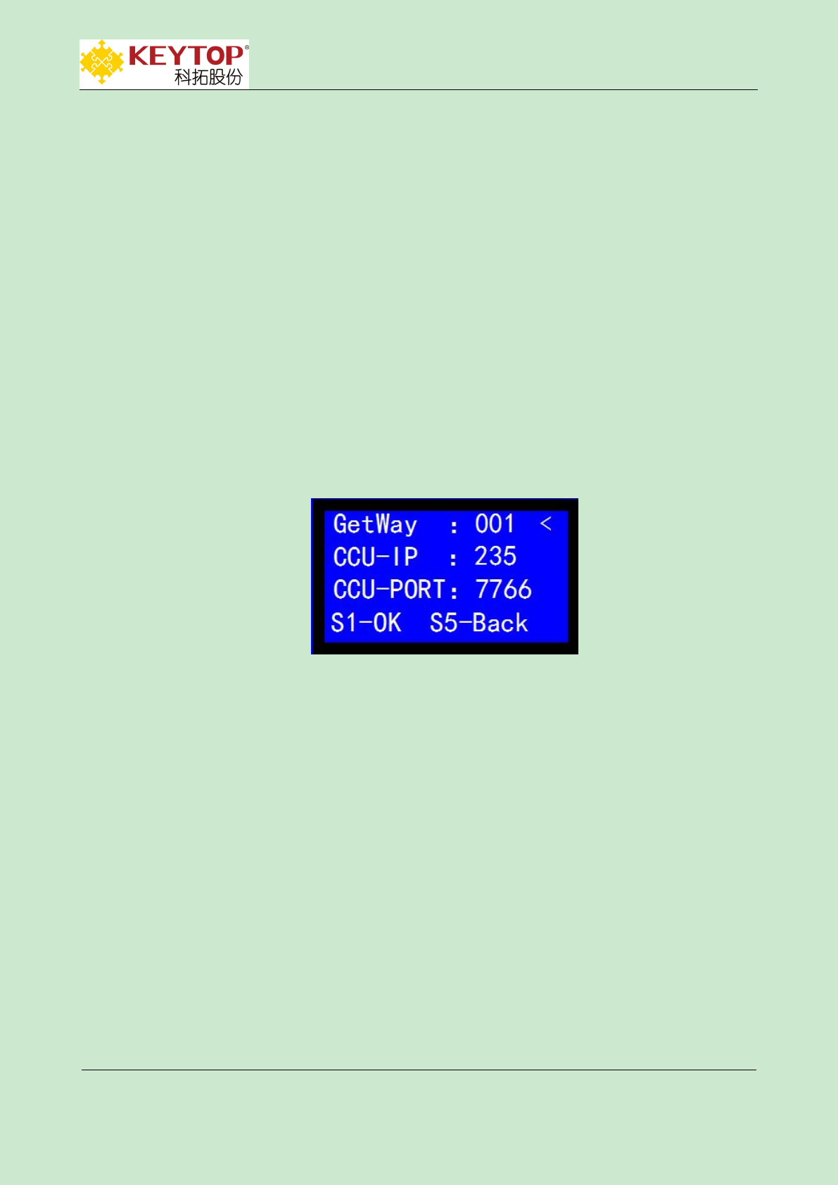
Pic.1-7 setting interface of network port
Getway(Network segment):001 network segment connected with node is 001;
CCU address:235 CCU address connected with node is 235;
CCU port:7766 CCU port connected with node is 7766;
Press button S4 to switch options,button S2 to add values,single click will add 1 value,long
press S2 will instantly add values;press button S3 to minus value,single click minus 1 value,long
press will instantly minus values; after setting,press button S1 to verify network port’s setting
information,press S5 to go back previous menu.Setting finished,repower on ZCU to make port
setting work.
Long press S5 to exit setting condition,go back to interface of detector’s status.
KEYTOP
KEYTOP Parking
Parking INC .
IN C.
Addr:Unit 301,No.58 GuanRi RD.,software Park,XiaMen,China
P.C:361008
TEL.:86-592-3521117
Fax:86-592-2611689
Web.:www.ikeytop.com
Email:zqb @keytop.com.cn
- 10 -
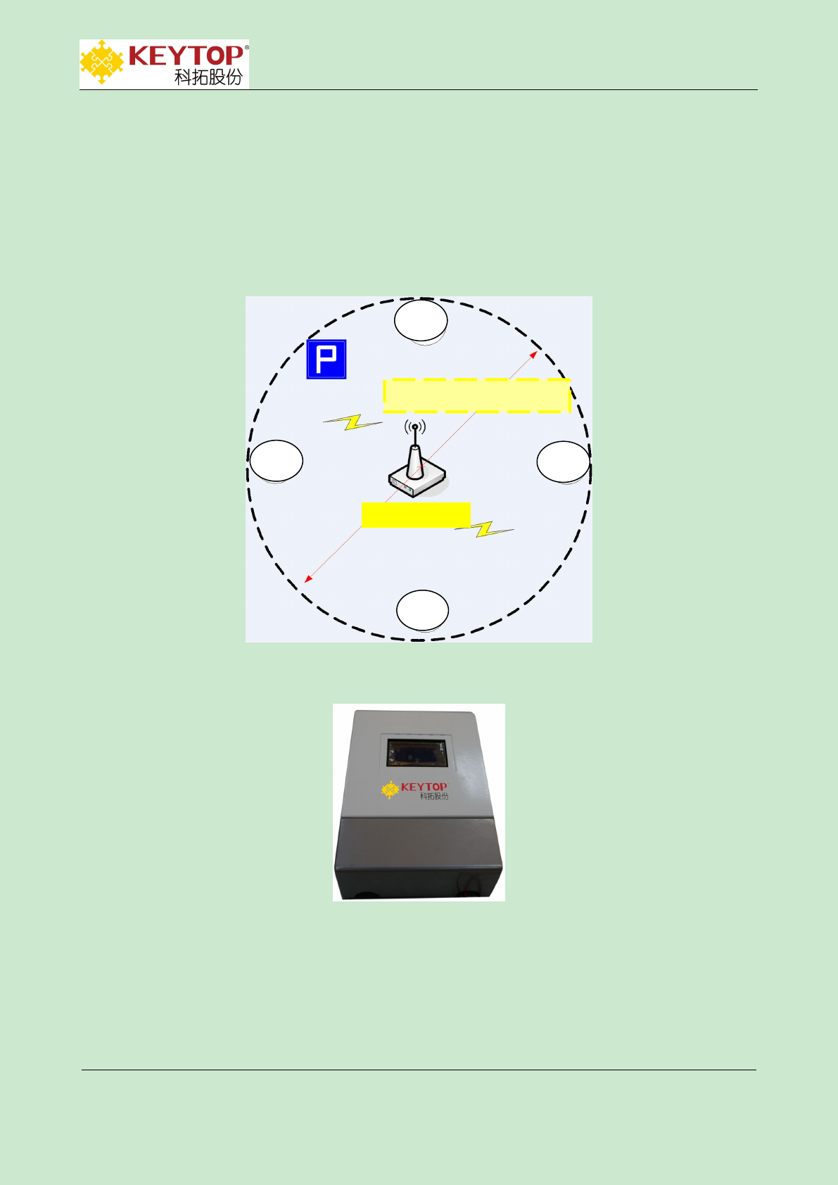
3.2.4 Installation of Wireless Detector ZCU
As showed in following digram,covering range of wireless ZCU is 30 meters.Thus installed
position of ZCU should be chosen according to parking spaces distribution.Aerial should be fasten
out of ZCU box at the height around 2.5 meters,without any large obstacles around and far away
from magnetic and iron objects.
3.3 Wireless Display ZCU
3.3.1 Parameters of Wireless Display ZCU
UD
UD
UD
UD
covering range:30m radius
Wireless ZCU

KEYTOP
KEYTOP Parking
Parking INC .
IN C.
Addr:Unit 301,No.58 GuanRi RD.,software Park,XiaMen,China
P.C:361008
TEL.:86-592-3521117
Fax:86-592-2611689
Web.:www.ikeytop.com
Email:zqb @keytop.com.cn
- 11 -
supply voltage:
110V/220V AC
working voltage:
5V DC
power dissipation:
3W
working
temperature:
-40~80℃
communication way:
communicate with wireless LED display through
915MHz,transmitting power:0dBm,covering range:200m
radius in vast space;
communicate with CCU by TCP/IP,can linked by network cable or WIFI.
size:
265mm*180mm*70mm(length*width*height)
3.3.2 Address Setting of Wireless Display ZCU
DIP switch (totally 8 jumpers,1 is high,8 is low):used for setting address of ZCU.ON means 1,OFF means
0.Eg.:address of 00000011 is 3(remarks:address of wireless display ZCU shouldn’t be repeated with that of
wireless detector ZCU;
Power supply port:VCC:+5V;GND--to ground;
LED indicator :red lamp is power supply indicator;green lamp is commands indicator of sending
display,when transmit display’s commands,it will flash one time;yellow lamp is CCU communication
lamp.The lamp doesn’t light up when failing to connect CCU.In the process of connecting
CCU,lamp will flash one time each 2 seconds.The lamp stays lighting up when
successfully linked to CCU.When CCU sends data to nodes,yellow lamp will flash quickly.
Buttons’ functions:
ZCU has 5 buttons,form up to down is:
(S1)pages switch button,(S2)add button,(S3)minus button,(S4)options switch
button,(S5)setting button
S1-pages switch button :In non-setting condition,press this button can switch pages of
different parking status.In setting condition,press this button to enter submenu of
cursor“<”.
S2-add button :In non-setting condition,press this button can inquire network port’s
configuration.In setting condition,press this button to act PLUS operation of corresponding
numbers of cursor.
S3-minus button :In setting condition,press this button to act MINUS operation of
corresponding numbers of cursor.
KEYTOP
KEYTOP Parking
Parking INC .
IN C.
Addr:Unit 301,No.58 GuanRi RD.,software Park,XiaMen,China
P.C:361008
TEL.:86-592-3521117
Fax:86-592-2611689
Web.:www.ikeytop.com
Email:zqb @keytop.com.cn
- 12 -
S4-options switch button:In setting condition,long press this button can swift cursor to
different setting options.
S5-setting button:In non-setting condition,long press this button until yellow lamp and
green lamp flash 3 times at the same time,it means entering the setting condition.In setting
process,press this button can go back to main setting menu.After setting,long press this
button until yellow and green lamps flash 3 times at the same time,which means exiting
setting condition.
3.3.3 Setting Instruction
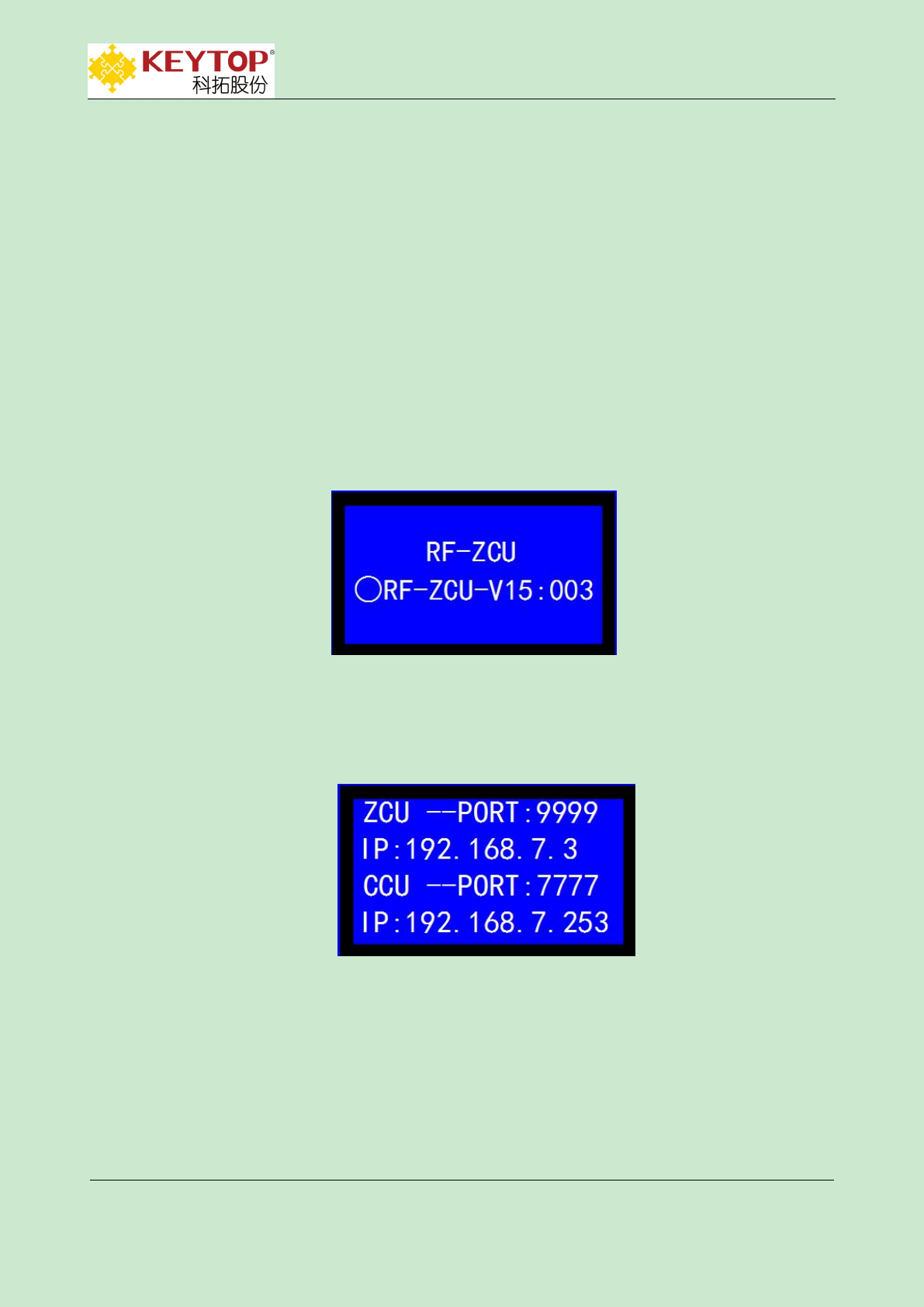
1. When powering on,interface appears as Pic.1-9
Pic.1-9 device version&address
“wireless display ZCU”means name of device;‘RF-ZCU-V15’ in the line of “○RF-ZCU-V15:003”means software
version,‘003’means the address of wireless node is 3;
2. Press button S2: enter inquire interface of network port setting,as showed in Pic.1-10:
Pic.1-10 inquire interface of network port setting
First line,ZCU--PORT:9999,means port No.of node is 9999;second line,IP:192.168.7.3,means IP address
of node192.168.7.3,the IP address namely is node address,which needn’t set up manually;third line,
CCU--PORT:7777,means CCU port No. is 7777;fourth line,IP:192.168.7.253,means IP address of CCU is
192.168.7.253;
3. Long press button S5: enter setting interface,as showed in Pic.1-11:
KEYTOP
KEYTOP Parking
Parking INC .
IN C.
Addr:Unit 301,No.58 GuanRi RD.,software Park,XiaMen,China
P.C:361008
TEL.:86-592-3521117
Fax:86-592-2611689
Web.:www.ikeytop.com
Email:zqb @keytop.com.cn
- 13 -
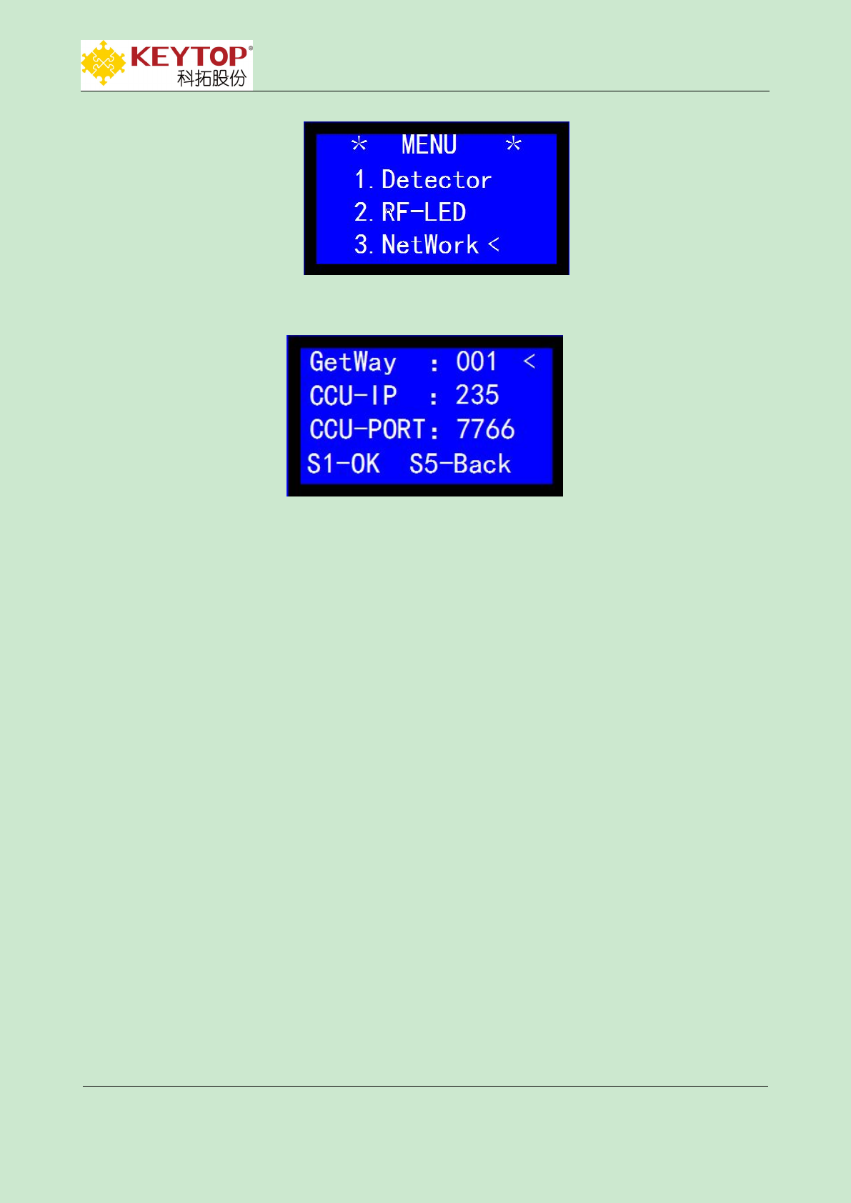
Pic.1-11 setting interface
press button S1:enter setting of network port and submenu setting of network port ,as showed in Pic.1-12
Pic.1-12 setting interface of network port
GetWay(Network segment):001 network segment connected with node is 001;
CCU address:235 CCU address connected with node is 235;
CCU port:7766 CCU port connected with node is 7766;
Press button S4 to switch options,button S2 to add values,single click will add 1 value,long
press S2 will instantly add values;press button S3 to minus value,single click minus 1 value,long
press will instantly minus values; after setting,press button S1 to verify network port’s setting
information,press S5 to go back previous menu.Setting finished,repower on nodes to make port
setting work.
Long press S5 to exit setting condition,go back to interface of detector’s status.
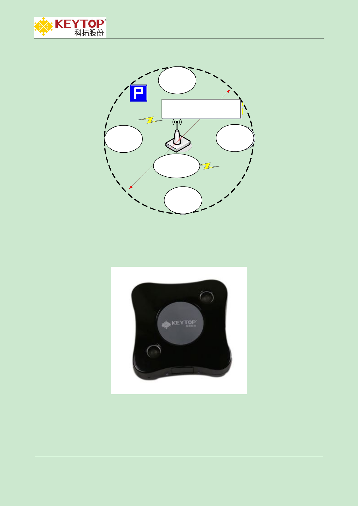
3.3.4 Installation of Wireless Display ZCU
As showed in following digram,covering range of wireless display node controller is 200
meters.Thus installed position of ZCU should be chosen according to wireless LED displays’
distribution.Aerial should be fasten out of node controller box at the height around 2.5
meters,without any large obstacles around and far away from magnetic and iron objects.
KEYTOP
KEYTOP Parking
Parking INC .
IN C.
Addr:Unit 301,No.58 GuanRi RD.,software Park,XiaMen,China
P.C:361008
TEL.:86-592-3521117
Fax:86-592-2611689
Web.:www.ikeytop.com
Email:zqb @keytop.com.cn
- 14 -
3.4 Wireless Ultrasonic Detector
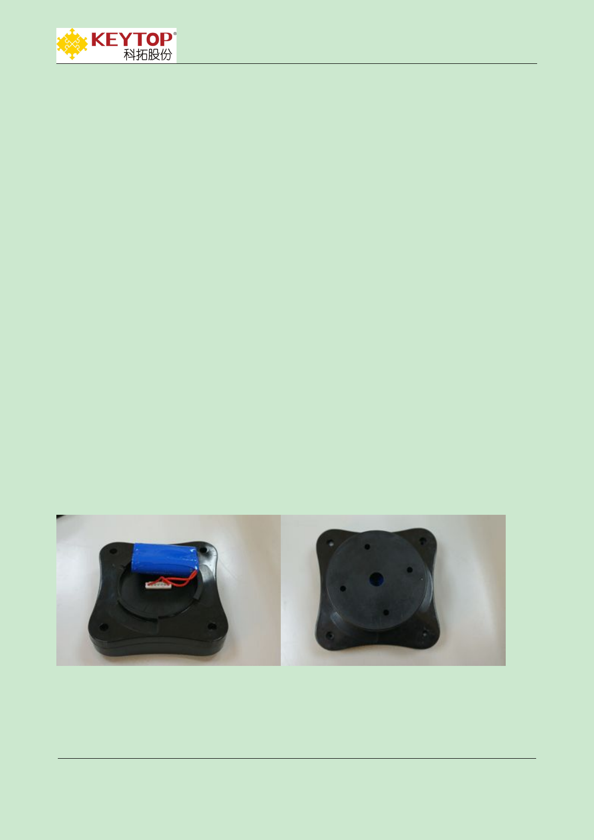
3.4.1 Appearance of Wireless Ultrasonic Detector
3.4.2 Parameters of Wireless Ultrasonic Detector
LED
display
LED
display
LED
display
LED
display
covering range: 200m radius
Wireless
ZCU
KEYTOP
KEYTOP Parking
Parking INC .
IN C.
Addr:Unit 301,No.58 GuanRi RD.,software Park,XiaMen,China
P.C:361008
TEL.:86-592-3521117
Fax:86-592-2611689
Web.:www.ikeytop.com
Email:zqb @keytop.com.cn
- 15 -
supply voltage:
1.5V
average power
dissipation:
90uW
power supply shelf:
>5 years
working
current:
60uA
power dissipation:
0dBm
communicate
distance:
about 30m
shell material:
ABS(anti-flaming,anti
-corrosion)
communication
way:
915MHz
maximum detecting
distance:
4m
working
temperature:
-40℃~+80℃
size:100mm*100mm
lithium iron
column battery :
FR6/AA
power supply
mode:
double battery parallel
operation
rated capacity of
single battery:
2900mAh
rated voltage :
1.5V
working
temperature:
-40℃~ +80℃
annual
discharge rate:
<1%
storage time:
>10 years
battery size:
diameter:14mm;height:50m
m
3.4.3 Address and Detecting Distance of Wireless Ultrasonic Detector
5、4、3、2、1
OFF
DIP2--8
setting
addresses
KEYTOP
KEYTOP Parking
Parking INC .
IN C.
Addr:Unit 301,No.58 GuanRi RD.,software Park,XiaMen,China
P.C:361008
TEL.:86-592-3521117
Fax:86-592-2611689
Web.:www.ikeytop.com
Email:zqb @keytop.com.cn
- 16 -
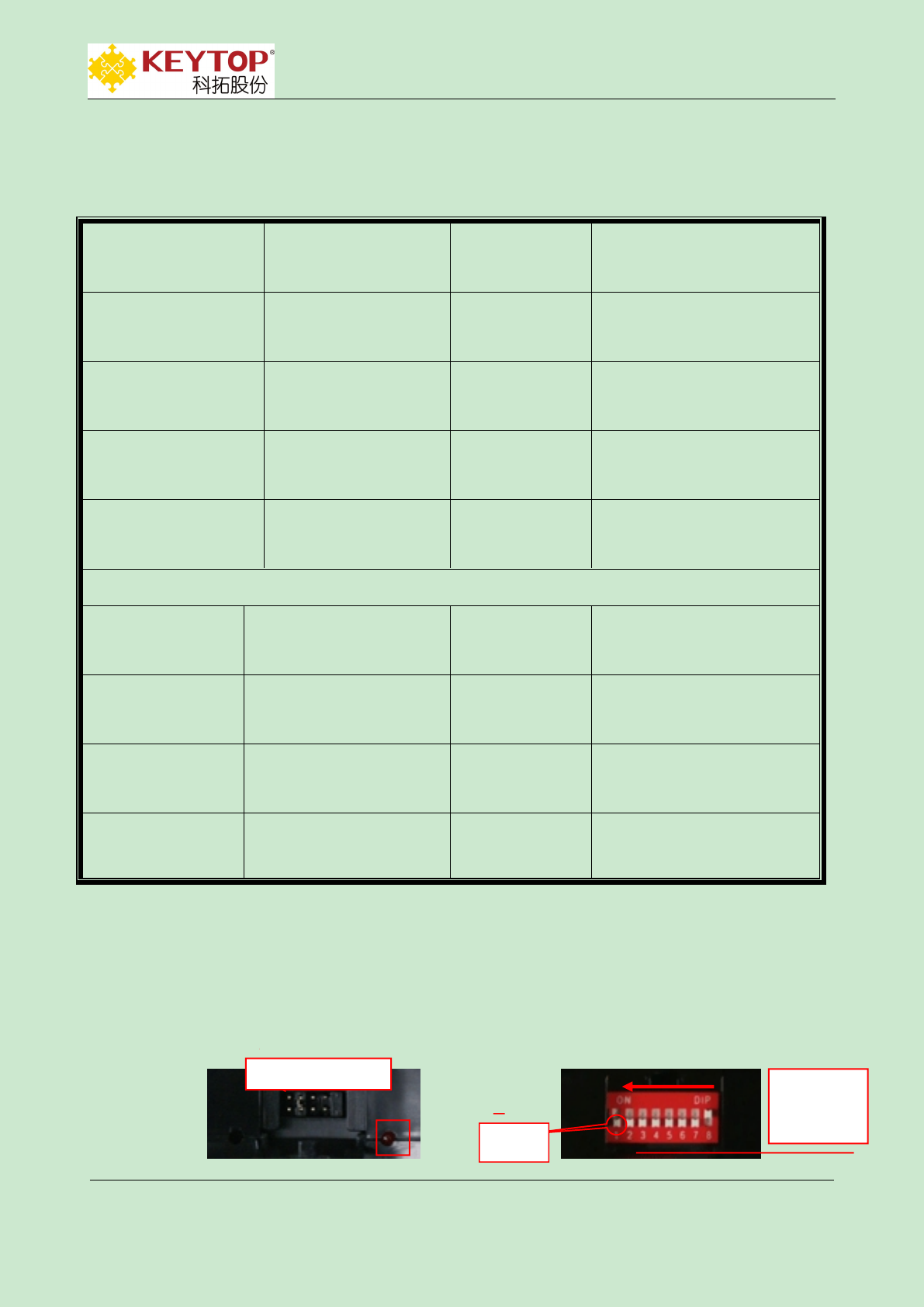
(a)jumper cap (b)DIP switch
1~5 jumper caps near red LED indicator is named as 1,from right to left in Pic.a are:1~5
No.1:power switch,jumper cap must be put on when using.
No.2:test usage.Put on jumper cap,when UD detects parking space is occupied,LED indicator
will light up.Otherwise,LED indicator will darken.
No.3~5:setting of detecting distance.:Put on No.3 jumper cap,then detecting distance is set up
for 0.5m;put on No.4 jumper cap,then detecting distance is set up for 1m;put on No.5 jumper
cap,then detecting distance is set up for 2m.Pic.(a) setting for 1m.Address setting of UD is divided
into two steps as follows:
3.4.4 Settings of Nodes Under Ultrasonic Detectors
Firstly fetch jumper caps of No.3 、4、5,then address set for DIP switch namely is node
address,power on detector for 2 seconds,and put address into detector.
3.4.5 Address Settings of Detectors(Address showed on ZCU)
Firstly cut power out of detectors,set addresses according to actual installation heights,thus
address of DIP switch namely is address of detectors,then power on detectors to work.
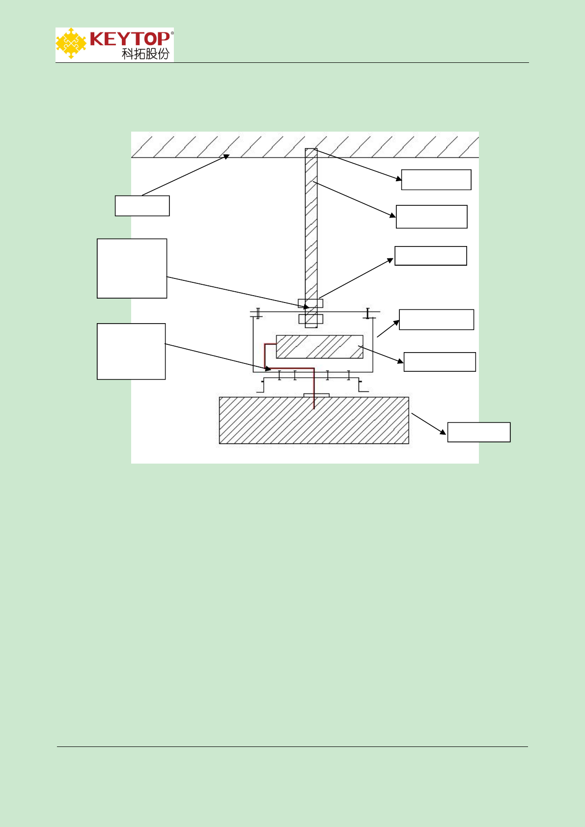
3.4.6 Installation of Wireless Ultrasonic Detector
KEYTOP
KEYTOP Parking
Parking INC .
IN C.
Addr:Unit 301,No.58 GuanRi RD.,software Park,XiaMen,China
P.C:361008
TEL.:86-592-3521117
Fax:86-592-2611689
Web.:www.ikeytop.com
Email:zqb @keytop.com.cn
- 17 -
Suspender installation: diameter of suspender is 0.8cm,length is set according to the height of UD
from ground.Therefore,UD’s height will be around 2m,2.5m,3m,3.5m,etc.Installation height of
2.5m is recommended.
Installation steps:
Suspender installation:fasten suspender onto ceiling by expansion head,right in the middle
of parking space.
Installation of UD’s bottom case: fasten bottom case onto suspender by screw nut,make
sure the direction of bottom case is as showed below,
UD
battery
bottom case
put UD and
bottom case
together by
rotating
screw nut
thread hole for
suspender to
cross bottom
case of UD
ceiling
suspender
expansion head
KEYTOP
KEYTOP Parking
Parking INC .
IN C.
Addr:Unit 301,No.58 GuanRi RD.,software Park,XiaMen,China
P.C:361008
TEL.:86-592-3521117
Fax:86-592-2611689
Web.:www.ikeytop.com
Email:zqb @keytop.com.cn
- 18 -
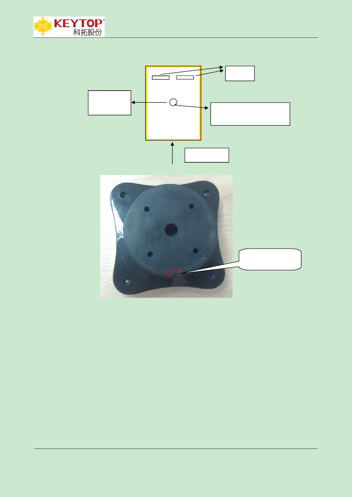
UD installation,press big hole of detector’s groove to bottom case and rotate them in
anticlockwise direction.Fasten detector to bottom case and ensure that two cameras in
detector are vertical with parking space after installation,as showed below,
vertical view
buffer
bottom case
of UD
Small notch angles 45°left
to passageway
small notch on
bottom case
KEYTOP
KEYTOP Parking
Parking INC .
IN C.
Addr:Unit 301,No.58 GuanRi RD.,software Park,XiaMen,China
P.C:361008
TEL.:86-592-3521117
Fax:86-592-2611689
Web.:www.ikeytop.com
Email:zqb @keytop.com.cn
- 19 -
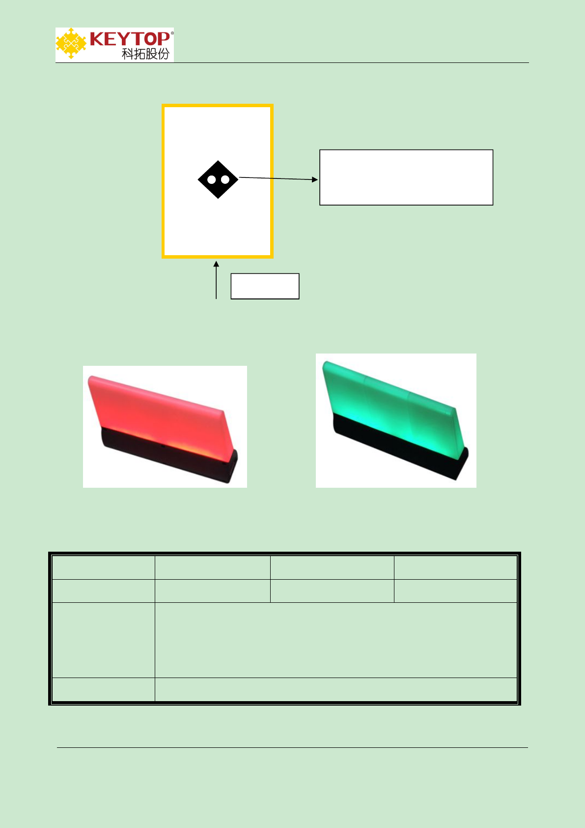
3.5 Wireless LED Indicator
(c)RED-occupied (d)GREEN-empty
3.5.1 Parameters of Wireless LED Indicator
supply voltage:
110V/220V AC
transmitting power:
0dBm
power dissipation:
1W
working temperature:
-40~80℃
communication
way:
1.communicate with Wireless Zone Control Unit(Wireless ZCU) by
915MHz,showing parking status by color changes of RED and
GREEN.Powering on,its color is RED.
2.communication distance:30m
size:
20mm*4.5mm*17mm(length*width*height)
two white loops are ultrasonic
cameras in UD,they are vertical with
parking spaces.
vertical view
KEYTOP
KEYTOP Parking
Parking INC .
IN C.
Addr:Unit 301,No.58 GuanRi RD.,software Park,XiaMen,China
P.C:361008
TEL.:86-592-3521117
Fax:86-592-2611689
Web.:www.ikeytop.com
Email:zqb @keytop.com.cn
- 20 -
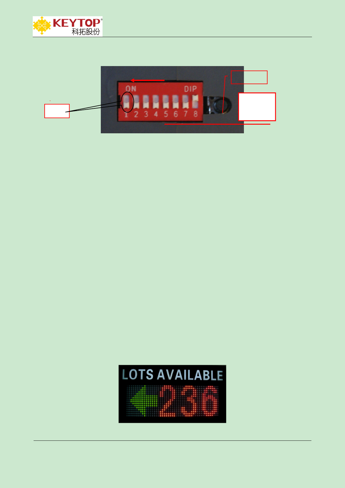
3.5.2 Address Setting of LED Indicator
(e)DIP switch of LED indicator
Set DIP -1 to ON,DIP-2~8 for setting addresses of nodes connected with LED indicator.Power
on LED indicator,green and red lights will flash alternatively and light off,it means address setting
of LED indicator is finished.
Under the condition of constant powering,set DIP-1 to OFF.Press ‘reset’key after setting
addresses of DIP-2~8.LED indicator will light off and turn to RED,which means the address
namely is that of LED indicator.The address of Pic.(e) is 02.
Due to the traits of mechanical parking spaces and installation method of detector,sometimes
the quantities of LED indicator and detectors do not always stay the same.For example,one LED
indictor is equipped with 6 detectors,LED indicator will turn RED as long as 5 detectors have
detected the parking spaces are occupied.Under such conditions,the quantity of LED indicator will
be 1 less than that of detector.Setting in this way:
DIP address setting: 0x79、0x7a、0x7b、0x7c、0x7d、0x7e、0x7f
Corresponding deduction value: 1、2、3、4、5、6、0
Press ‘reset’key,times that green and red indicators lights up together namely is the deduction
value.
3.6 Wireless LED Display
OFF
DIP2--8
setting
add.:01
reset key
KEYTOP
KEYTOP Parking
Parking INC .
IN C.
Addr:Unit 301,No.58 GuanRi RD.,software Park,XiaMen,China
P.C:361008
TEL.:86-592-3521117
Fax:86-592-2611689
Web.:www.ikeytop.com
Email:zqb @keytop.com.cn
- 21 -
3.6.1 Parameters of Wireless LED Display
supply voltage:
110V/220V AC
working voltage:
5VDC
power dissipation:
related to the size of LED
display
communication
way:
915MHz
working
temperature:
-40℃~+80℃
size:
customized
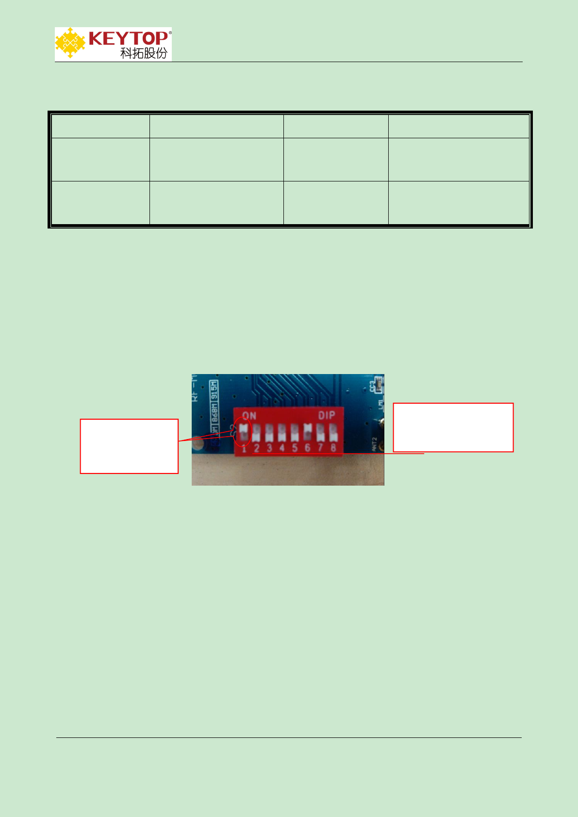
3.6.2 Address Setting of Wireless Transmitting Module
DIP switch(totally 8 jumpers,1 is high) is to set address of wireless display nodes.ON is 1,OFF
is 0.Set DIP1 to ON,baud rate is 9600,set to OFF,baud rate is 4800.DIP-2~8 are addresses.
Eg.:set wireless display node’s address be 04,baud rate 9600,then DIP is 10000100,as showed
below,
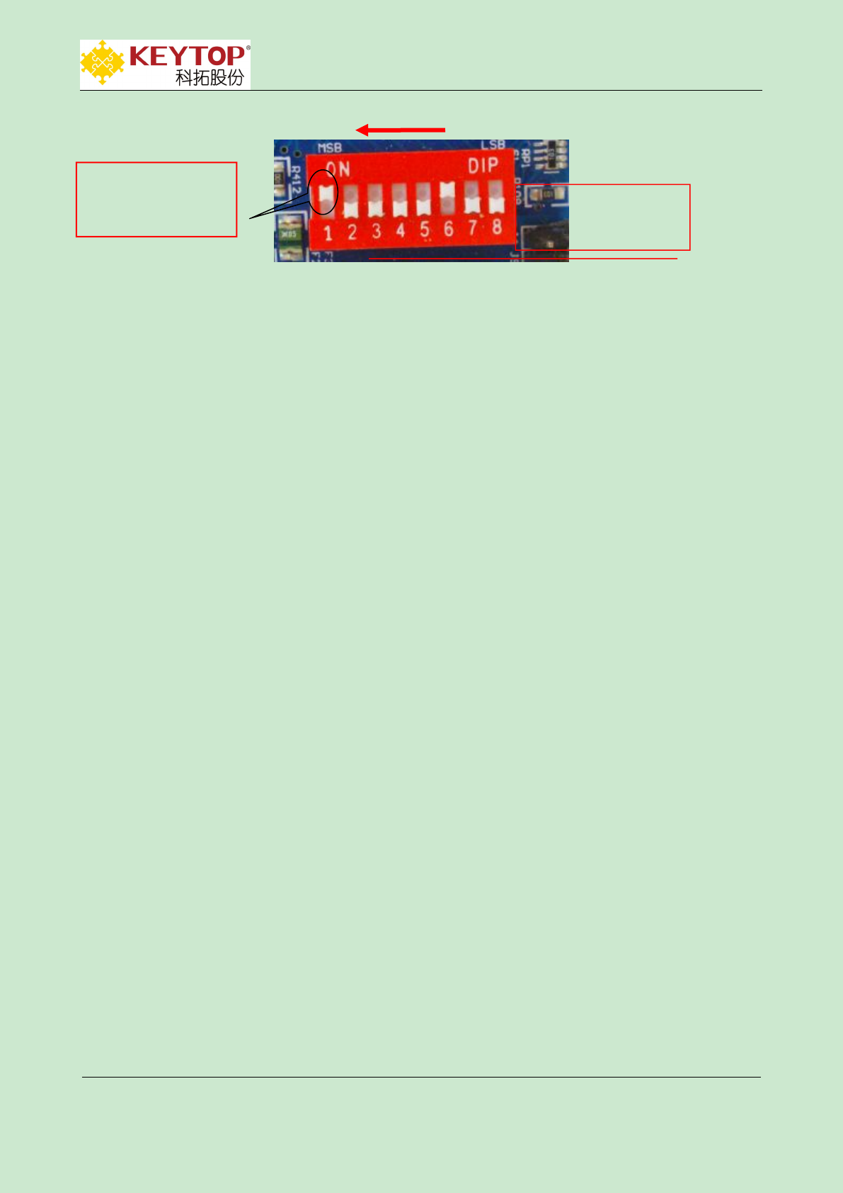
3.6.3 Address Setting of LED Display Controller Card
DIP switch(totally 8 jumpers,1 is high) is to set address of wireless display.ON is 1,OFF is
0.Set DIP1 to ON,baud rate is 9600,set to OFF,baud rate is 4800.DIP2 doesn’t applied.Others are
addresses.See attachment 9-1.
For example,to set display address be 04,baud rate 9600,then DIP will be 10000100,as showed
below,
DIP-1 setting baud
rate
ON--9600
OFF--4800
DIP2--8 setting address
2(high)←—8(low)
KEYTOP
KEYTOP Parking
Parking INC .
IN C.
Addr:Unit 301,No.58 GuanRi RD.,software Park,XiaMen,China
P.C:361008
TEL.:86-592-3521117
Fax:86-592-2611689
Web.:www.ikeytop.com
Email:zqb @keytop.com.cn
- 22 -
REMARKS:baud rate of display controller card should be conformed to that of wireless
transmitting module.
DIP3--8 setting display
address
3(high)←—8(low)
DIP-1 setting baud rate
ON--9600
OFF--4800

KEYTOP
KEYTOP Parking
Parking INC .
IN C.
Addr:Unit 301,No.58 GuanRi RD.,software Park,XiaMen,China
P.C:361008
TEL.:86-592-3521117
Fax:86-592-2611689
Web.:www.ikeytop.com
Email:zqb @keytop.com.cn
- 23 -
Addendum 1-1 Ultrasonic Detector Address Settings
DIP switch of ultrasonic detector has 8 ranks,one is the highest rank,8 is the lowest rank。
“ON” means“1”,the corresponding mark in below diagram is “●”;“OFF”means“0”the corresponding
mark in below diagram is“○”。
Detector Addr.
DIP Switch
2(high)←—8(low)
Detector Addr.
Decimal System
Hexadecimal
2
3
4
5
6
7
8
Decimal System
Hexadecimal
2
3
4
5
6
7
8
1
01
○
○
○
○
○
○
●
16
10
○
○
●
○
○
○
○
2
02
○
○
○
○
○
●
○
17
11
○
○
●
○
○
○
●
3
03
○
○
○
○
○
●
●
18
12
○
○
●
○
○
●
○
4
04
○
○
○
○
●
○
○
19
13
○
○
●
○
○
●
●
5
05
○
○
○
○
●
○
●
20
14
○
○
●
○
●
○
○
6
06
○
○
○
○
●
●
○
21
15
○
○
●
○
●
○
●
7
07
○
○
○
○
●
●
●
22
16
○
○
●
○
●
●
○
8
08
○
○
○
●
○
○
○
23
17
○
○
●
○
●
●
●
9
09
○
○
○
●
○
○
●
24
18
○
○
●
●
○
○
○
10
0A
○
○
○
●
○
●
○
25
19
○
○
●
●
○
○
●
11
0B
○
○
○
●
○
●
●
26
1A
○
○
●
●
○
●
○
12
0C
○
○
○
●
●
○
○
27
1B
○
○
●
●
○
●
●
13
0D
○
○
○
●
●
○
●
28
1C
○
○
●
●
●
○
○
14
0E
○
○
○
●
●
●
○
29
1D
○
○
●
●
●
○
●
15
0F
○
○
○
●
●
●
●
30
1E
○
○
●
●
●
●
○
31
1F
○
○
●
●
●
●
●
46
2E
○
●
○
●
●
●
○
32
20
○
●
○
○
○
○
○
47
2F
○
●
○
●
●
●
●
33
21
○
●
○
○
○
○
●
48
30
○
●
●
○
○
○
○
34
22
○
●
○
○
○
●
○
49
31
○
●
●
○
○
○
●
35
23
○
●
○
○
○
●
●
50
32
○
●
●
○
○
●
○
36
24
○
●
○
○
●
○
○
51
33
○
●
●
○
○
●
●
37
25
○
●
○
○
●
○
●
52
34
○
●
●
○
●
○
○
38
26
○
●
○
○
●
●
○
53
35
○
●
●
○
●
○
●
39
27
○
●
○
○
●
●
●
54
36
○
●
●
○
●
●
○
40
28
○
●
○
●
○
○
○
55
37
○
●
●
○
●
●
●
41
29
○
●
○
●
○
○
●
56
38
○
●
●
●
○
○
○
42
2A
○
●
○
●
○
●
○
57
39
○
●
●
●
○
○
●
43
2B
○
●
○
●
○
●
●
58
3A
○
●
●
●
○
●
○
44
2C
○
●
○
●
●
○
○
59
3B
○
●
●
●
○
●
●
45
2D
○
●
○
●
●
○
●
60
3C
○
●
●
●
●
○
○
Remark:The address setting of ZCU and led display can refer to this diagram.ZCU DIP switch:1(high rank)←
8(low rank);Display DIP switch 2(high rank)←8(low rank),1 is to set baud rate,ON-9600,OFF-4800
FCC Caution: Any changes or modifications not expressly approved by the party responsible
for compliance could void the user's authority to operate this equipment.
This device complies with Part 15 of the FCC Rules. Operation is subject to the following two
conditions:(1)This device may not cause harmful interference, and (2) this device must accept
any interference received, including interference that may cause undesired operation.
NOTE: This equipment has been tested and found to comply with the limits for a Class B
digital device, pursuant to Part 15 of the FCC Rules.
These limits are designed to provide reasonable protection against harmful interference in a
residential installation. This equipment generates, uses and can radiate radio frequency
energy and, if not installed and used in accordance with the instructions, may cause harmful
interference to radio communications.
However, there is no guarantee that interference will not occur in a particular installation.
If this equipment does cause harmful interference to radio or television reception, which can be
determined by turning the equipment off and on, the user is encouraged to try to correct the
interference by one or more of the following measures:
FCC RF Radiation Exposure Statement:
This equipment complies with FCC radiation exposure limits set forth for an uncontrolled
environment End users must follow the specific operating instructions for satisfying RF
exposure compliance. This transmitter must not be collocated or operating in conjunction with
any other antenna or transmitter.
The device has been evaluated to meet general RF exposure requirement. The device can be
used in portable exposure condition without restriction.