Xiamen Keytop Comm and Tech KEY-WT06 Wireless Ultrasonic Sensor User Manual

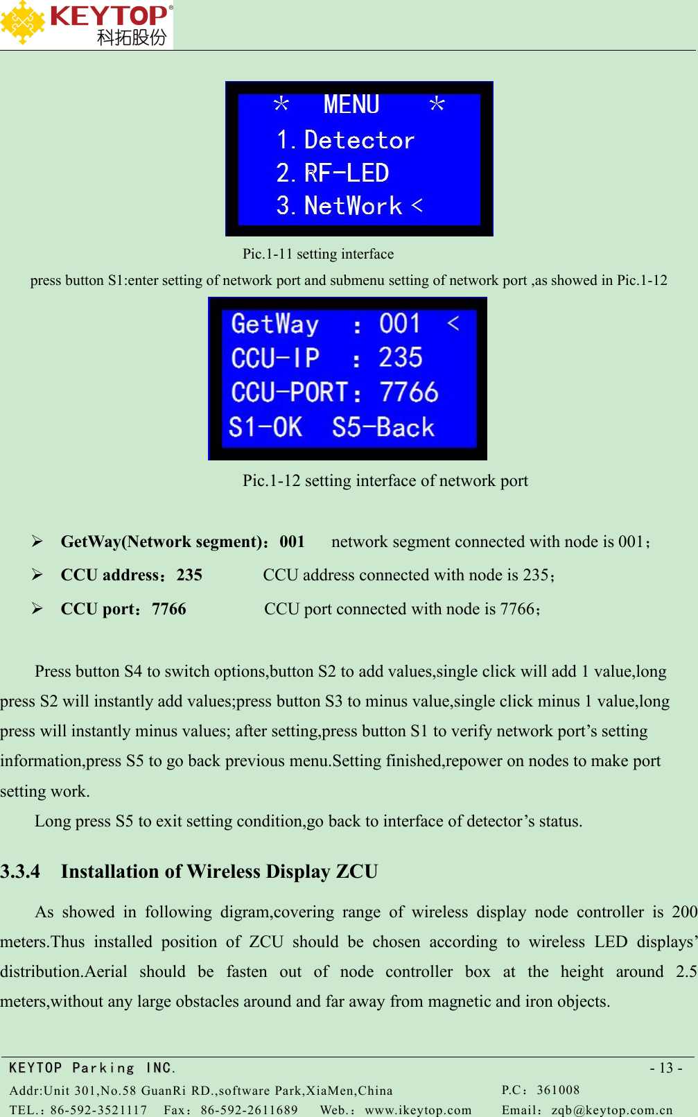
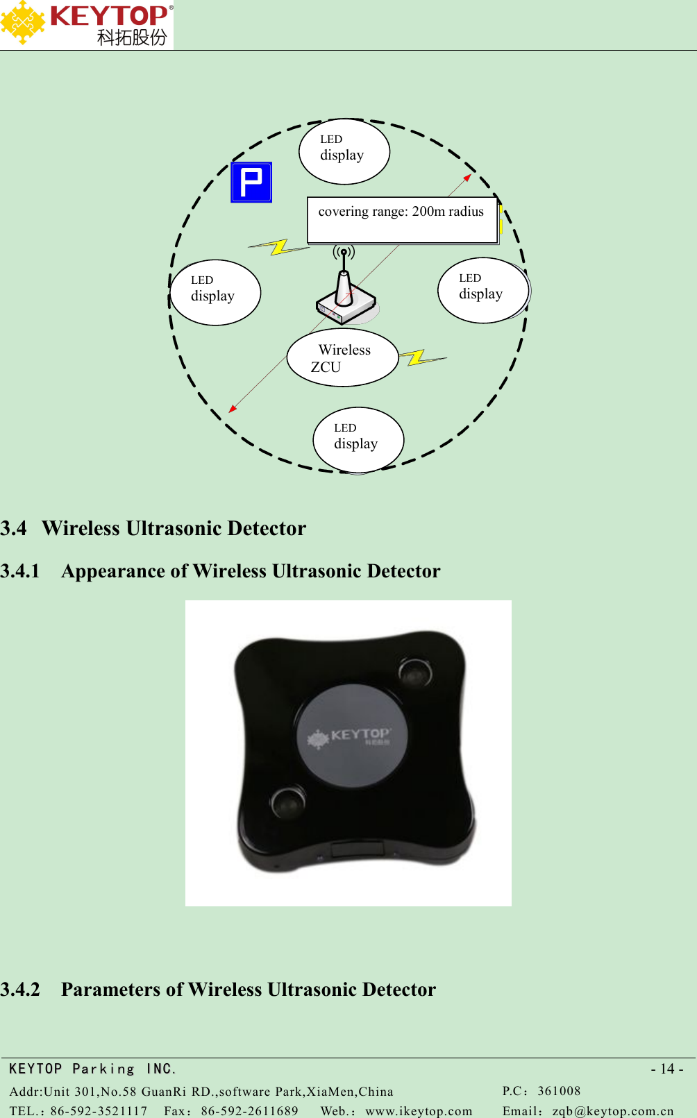
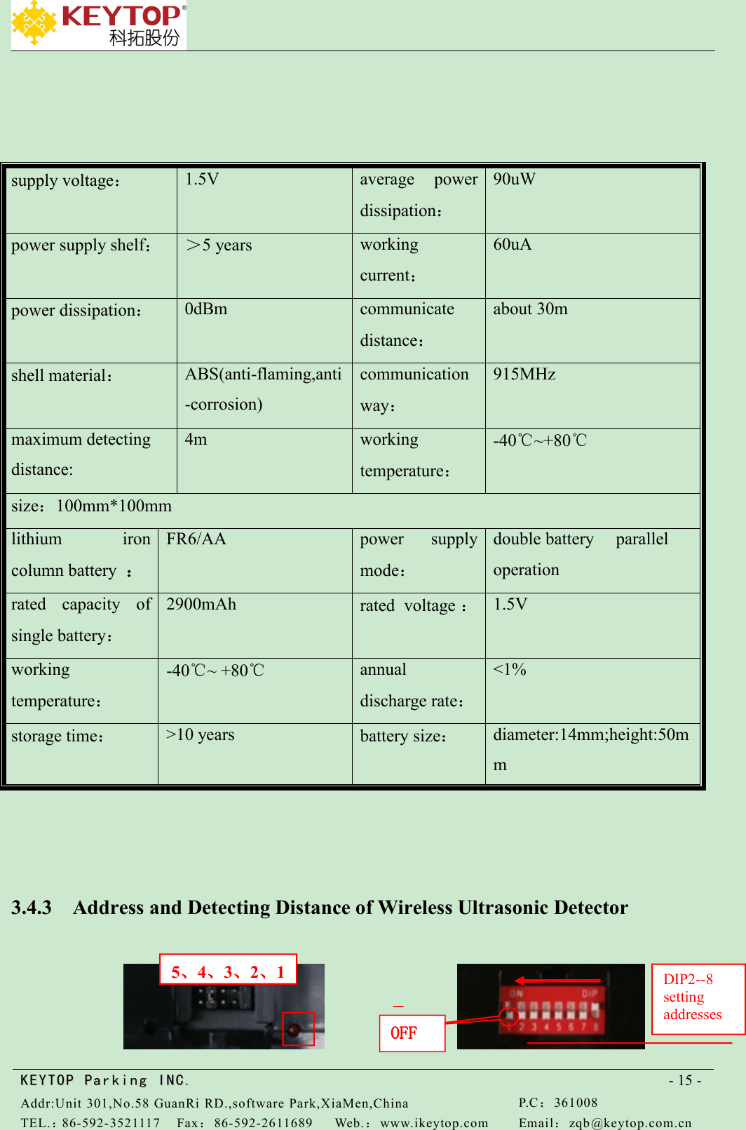
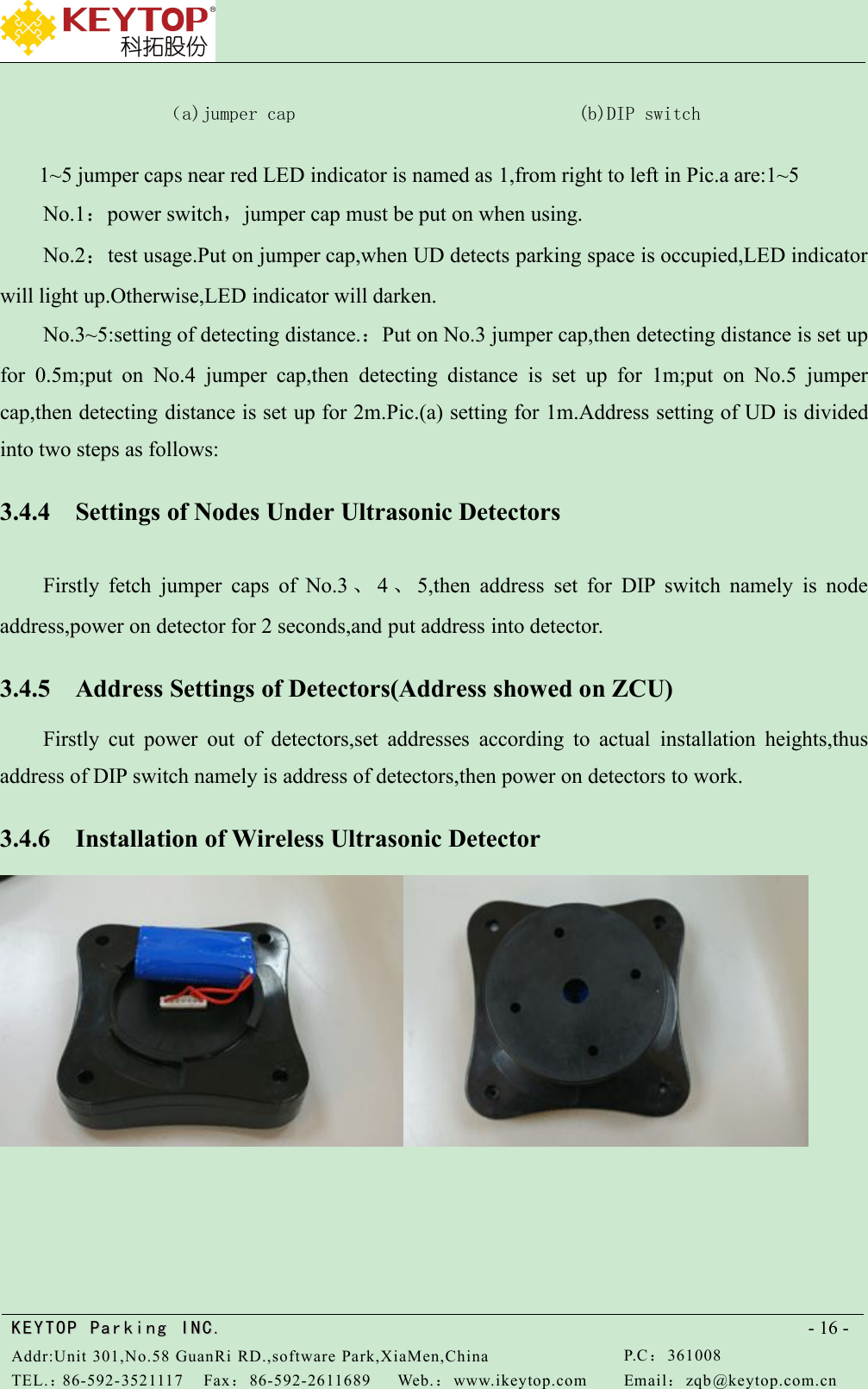
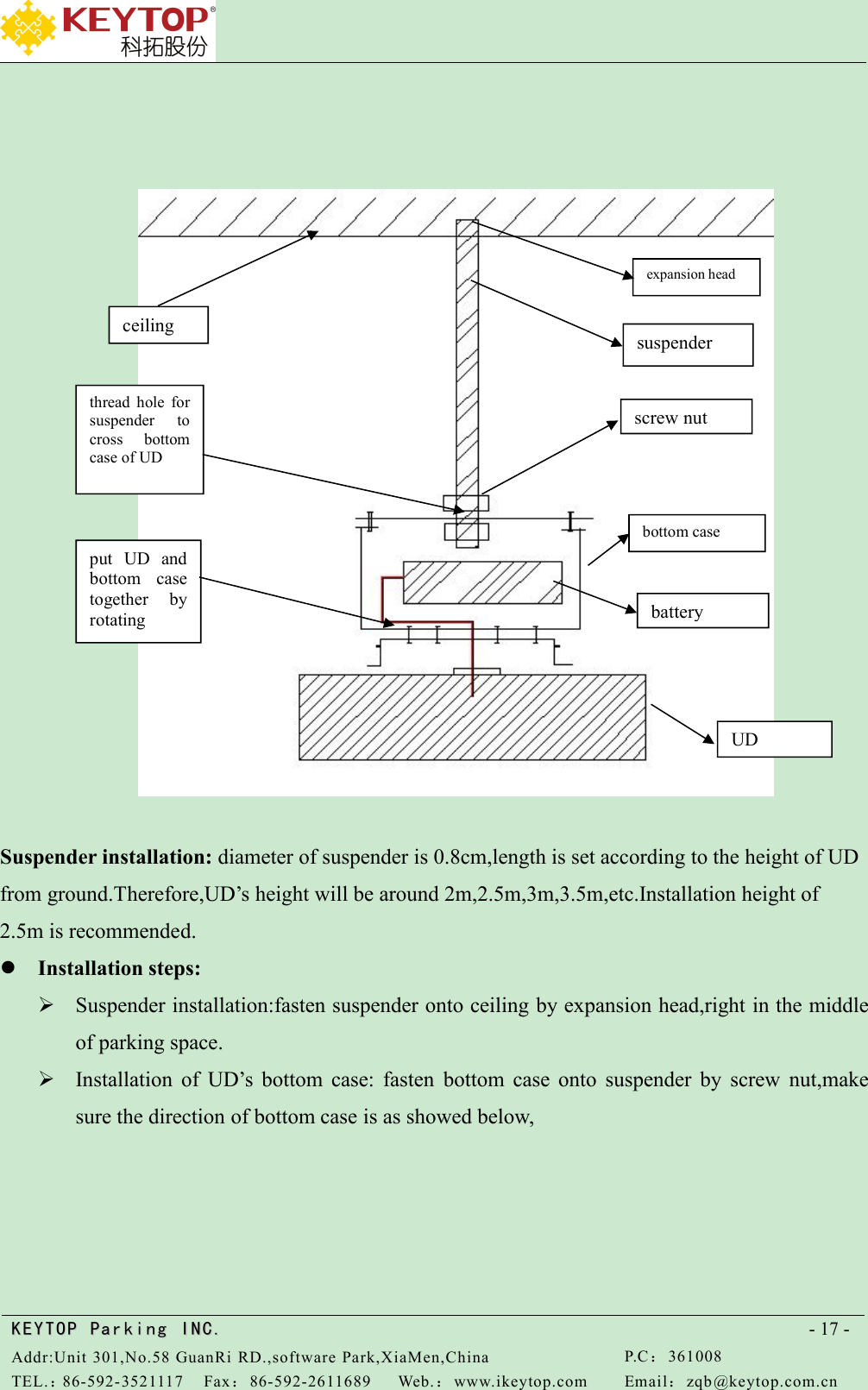
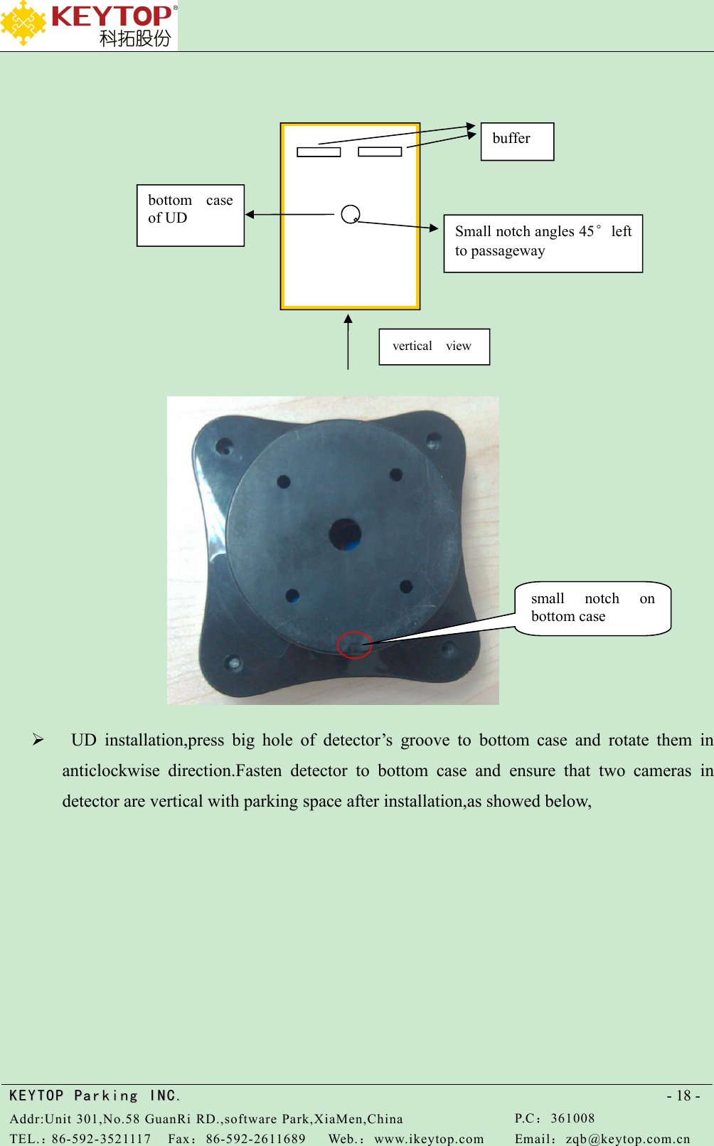
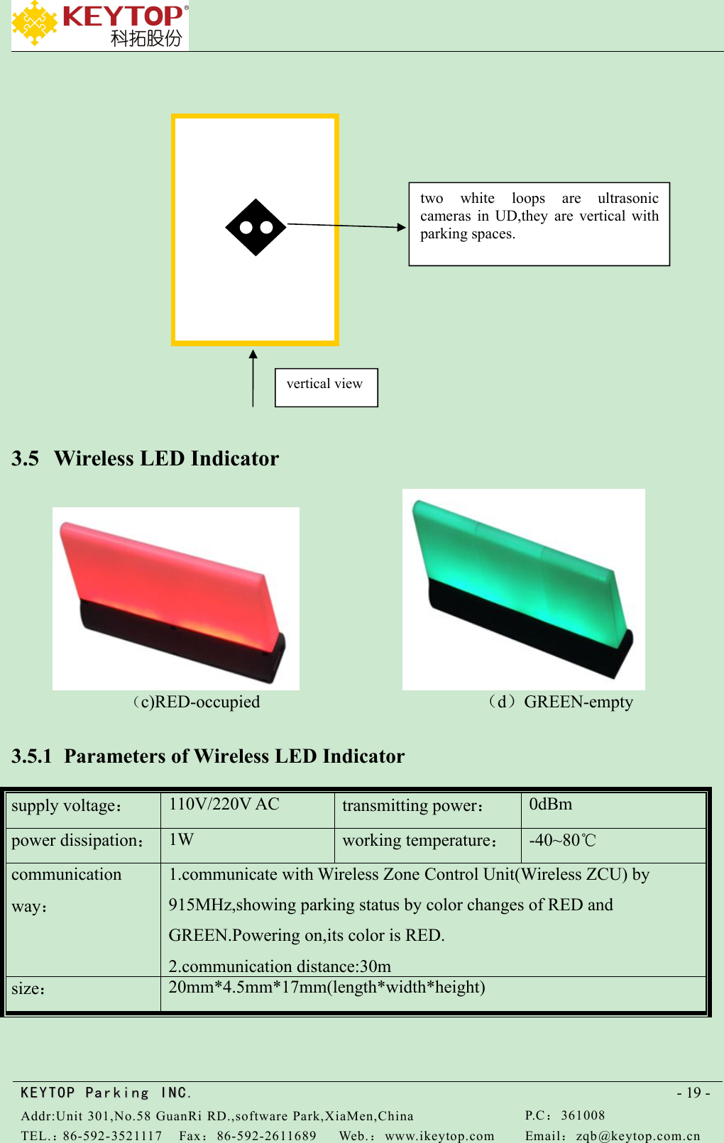
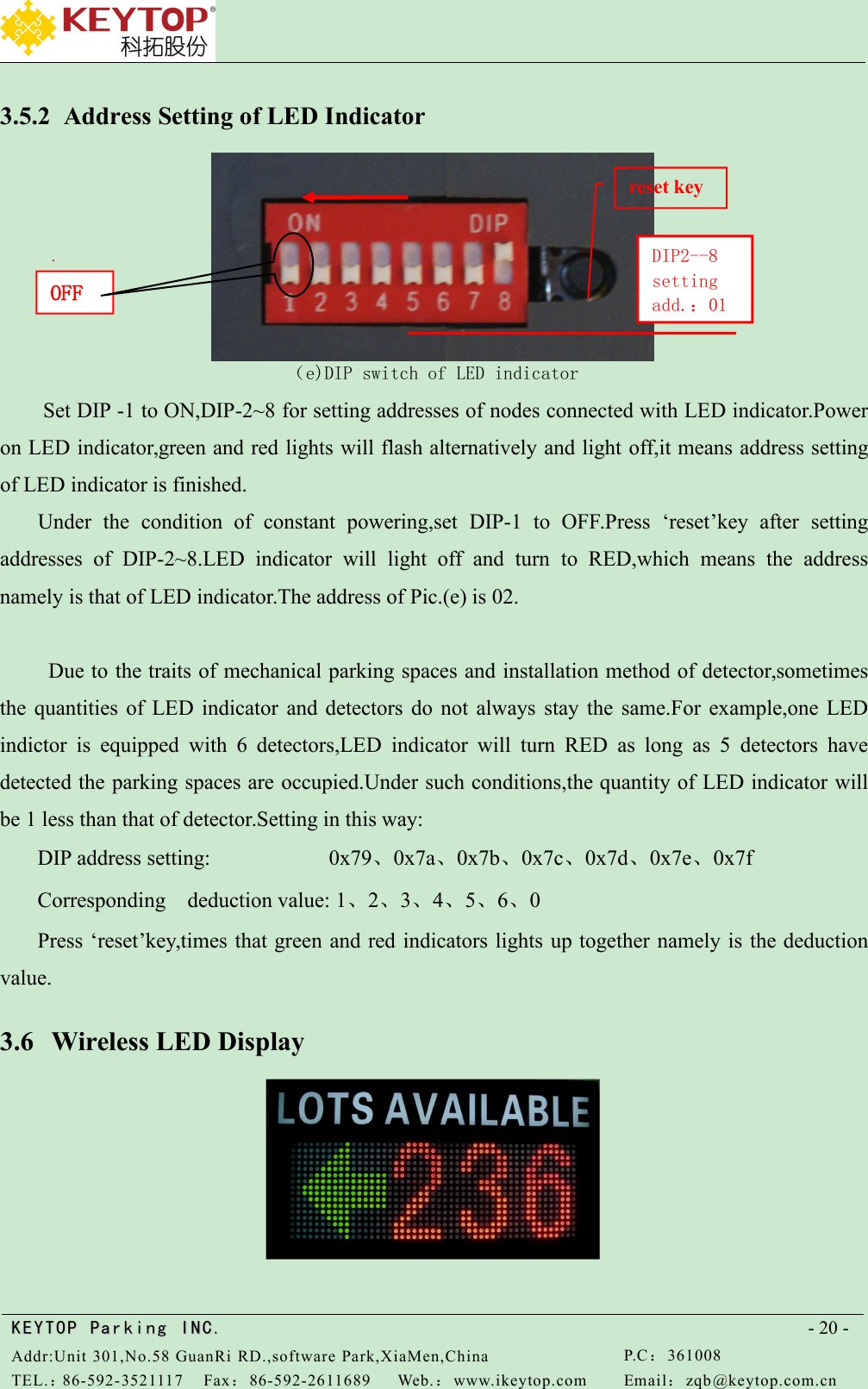
Xiamen Keytop Comm.&Tech.Co.;,Ltd Wireless Ultrasonic Sensor

User Manual

Wireless ParkingGuidance System ManualThe China brand enterprise of top-selling parking guidance systemsKEYTOP Parking INC.
KEYTOPKEYTOP ParkingParking INC .IN C.Addr:Unit 301,No.58 GuanRi RD.,software Park,XiaMen,ChinaP.C:361008TEL.:86-592-3521117Fax:86-592-2611689Web.:www.ikeytop.comEmail:zqb @keytop.com.cn- 1 -Catalogue1 Principle of Wireless Parking Guidance System............................................................ - 2 -2 Diagram of Wireless Parking Guidance System.............................................................- 2 -3 Devices Instructions........................................................................................................- 3 -3.1 Central Control Unit(CCU)................................................................................................ - 3 -3.1.1 Parameters of CCU................................................................................................... - 3 -3.1.2 Introduction of CCU Port......................................................................................... - 3 -3.1.3 Configuration of CCU.............................................................................................. - 4 -3.2 Wireless Detector ZCU....................................................................................................... - 4 -3.2.1 Parameters of Wireless ZCU.....................................................................................- 4 -3.2.2 Introduction of ZCU Control Panel.......................................................................... - 5 -3.2.3 Setting Instruction.....................................................................................................- 6 -3.2.4 Installation of Wireless Detector ZCU....................................................................- 10 -3.3 Wireless Display ZCU...................................................................................................... - 10 -3.3.1 Parameters of Wireless Display ZCU..................................................................... - 10 -3.3.2 Address Setting of Wireless Display ZCU..............................................................- 11 -3.3.3 Setting Instruction...................................................................................................- 12 -3.3.4 Installation of Wireless Display ZCU..................................................................... - 13 -3.4 Wireless Ultrasonic Detector............................................................................................ - 14 -3.4.1 Appearance of Wireless Ultrasonic Detector..........................................................- 14 -3.4.2 Parameters of Wireless Ultrasonic Detector........................................................... - 14 -3.4.3 Address and Detecting Distance of Wireless Ultrasonic Detector..........................- 15 -3.4.4 Settings of Nodes Under Ultrasonic Detectors....................................................... - 16 -3.4.5 Address Settings of Detectors(Address showed on ZCU)......................................- 16 -3.4.6 Installation of Wireless Ultrasonic Detector........................................................... - 16 -3.5 Wireless LED Indicator.....................................................................................................- 19 -3.5.1 Parameters of Wireless LED Indicator................................................................... - 19 -3.5.2 Address Setting of LED Indicator........................................................................- 20 -3.6 Wireless LED Display.......................................................................................................- 20 -3.6.1 Parameters of Wireless LED Display..................................................................... - 21 -3.6.2 Address Setting of Wireless Transmitting Module................................................. - 21 -3.6.3 Address Setting of LED Display Controller Card.................................................. - 21 -Addendum 1-1 Ultrasonic Detector Address Settings................................................................... - 23 -
KEYTOPKEYTOP ParkingParking INC .IN C.Addr:Unit 301,No.58 GuanRi RD.,software Park,XiaMen,ChinaP.C:361008TEL.:86-592-3521117Fax:86-592-2611689Web.:www.ikeytop.comEmail:zqb @keytop.com.cn- 2 -1 Principle of Wireless Parking Guidance SystemWireless ultrasonic detector detects the status of parking lot,then sends real-time parking lotinformation to the corresponding wireless detector ZCUs by wireless RF signal.ThroughWIFI ,wireless ZCU sends the collected parking information to wireless routers connected toCCU.After collecting information of the whole carport,CCU updates parking lot data intime.Wireless routers sends these data to corresponding LED displays by LED display ZCU.In thisway,wireless parking guidance system realizes the function of guiding vehicles to empty parkingspaces.Remark:it's better to use separated ZCU for the led display to ensure the system's workingstabilities,so the system has detector ZCU and display ZCU.2 Diagram of Wireless Parking Guidance System
KEYTOPKEYTOP ParkingParking INC .IN C.Addr:Unit 301,No.58 GuanRi RD.,software Park,XiaMen,ChinaP.C:361008TEL.:86-592-3521117Fax:86-592-2611689Web.:www.ikeytop.comEmail:zqb @keytop.com.cn- 3 -3 Devices Instructions3.1 Central Control Unit(CCU)3.1.1 Parameters of CCU3.1.2 Introduction of CCU PortUSB upgrade port:insert upgrading U disk to USB port,get power on to CCU,then CCUprocedure will upgrade automatically.Wireless router port:CCU is connected to wireless router.To visit CCU by computer,pleasesupply voltage:110V/220V ACworking voltage:5VDCpower dissipation:5.8Wcommunication way:TCP/IPoperating system:WINDOWS XP-Esize:28.5*22*5CMpowerindicatorUSB upgradeportwireless routerportresetbutton
KEYTOPKEYTOP ParkingParking INC .IN C.Addr:Unit 301,No.58 GuanRi RD.,software Park,XiaMen,ChinaP.C:361008TEL.:86-592-3521117Fax:86-592-2611689Web.:www.ikeytop.comEmail:zqb @keytop.com.cn- 4 -link network cable to wireless router’s LAN port.When only one node controller is connectedand communication distance less than 100 meters,wireless router port can directlycommunicate to CCU port.3.1.3 Configuration of CCUTo make LED display show correct information,it needs to configurate the CCU.Otherwise,LEDdisplay will only show initial content of powering-on(000+arrow).3.2 Wireless Detector ZCU3.2.1 Parameters of Wireless ZCUsupply voltage:110V/220V ACworking voltage:5V DCpower dissipation:3Wworking temperature:-40~80℃communication way:1.communicate with wireless detector by 915MHz,transmittingpower:0dBm,covering range:30m radius. Can be linked with 120detector at most.2.communicate with CCU by TCP/IP,can be linked by network cable orWIFI.size:265mm*180mm*70mm(length*width*height)
KEYTOPKEYTOP ParkingParking INC .IN C.Addr:Unit 301,No.58 GuanRi RD.,software Park,XiaMen,ChinaP.C:361008TEL.:86-592-3521117Fax:86-592-2611689Web.:www.ikeytop.comEmail:zqb @keytop.com.cn- 5 -3.2.2 Introduction of ZCU Control PanelZCU Control PanelDIP Switch(total 8 jumpers,1 is high,8 is low)Switch digits(pic.b)12345678Switch value(ON-effective)1286432168421For example,set ZCU address 5.5=4+1,set serial No. 6 and No.8 to ON,address setting finished,ZCU address will be 5 afterrepowering on.Buttons:S1 pages switchS2 addS3 minusS4 options switchS5 settingpowersupply port+5V GNDDIP switch1 is high position,8 is lowposition.NO means 1,OFF means0indicator lights:red,green,yellowaerialLCD display
KEYTOPKEYTOP ParkingParking INC .IN C.Addr:Unit 301,No.58 GuanRi RD.,software Park,XiaMen,ChinaP.C:361008TEL.:86-592-3521117Fax:86-592-2611689Web.:www.ikeytop.comEmail:zqb @keytop.com.cn- 6 -supply power port:VCC---+5V;GND---ground;LED indicator:red:power supply lamp;green:detector’s communication lamp,when detector sends data to detector ZCU,thegreen lamp will flash.yellow :CCU communication lamp.The lamp doesn’t light up when failing to connectCCU.In the process of connecting CCU,lamp will flash one time each 2 seconds.The lampstays lighting up when successfully linked to CCU.When CCU sends data to ZCU,yellowlamp will flash quickly.Buttons’ functions:ZCU has 5 buttons,from up to down is:(S1)pages switch button,(S2)add button,(S3)minus button,(S4)options switchbutton,(S5)setting buttonS1-pages switch button:In non-setting condition,press this button can switch pages ofdifferent parking status.In setting condition,press this button to enter submenu ofcursor“<”.S2-add button :In non-setting condition,press this button can inquire network port’sconfiguration.In setting condition,press this button to act PLUS operation of correspondingnumbers of cursor.S3-minus button :In setting condition,press this button to act MINUS operation ofcorresponding numbers of cursor.S4-options switch button:In setting condition,long press this button can swift cursor todifferent setting options.S5-setting button:In non-setting condition,long press this button until yellow lamp andgreen lamp flash 3 times at the same time,it means entering the setting condition.In settingprocess,press this button can go back to main setting menu.After setting,long press thisbutton until yellow and green lamps flash 3 times at the same time,which means exitingsetting condition.3.2.3 Setting Instruction1.When powering on,press button S1 can switch 3 interfaces as showed in Pic.1-2:
KEYTOPKEYTOP ParkingParking INC .IN C.Addr:Unit 301,No.58 GuanRi RD.,software Park,XiaMen,ChinaP.C:361008TEL.:86-592-3521117Fax:86-592-2611689Web.:www.ikeytop.comEmail:zqb @keytop.com.cn- 7 -(a)device version&address (b)1~60 detector’s status (c) 61~120 detector’s statusPic. 1-2(a)"Detector ZCU"means name of device,"RF-ZCU-V04"means version ofsoftware,"003"means the address of detector ZCU is 3;(b)(c)means the ZCU is connected with 3detectors,"●" means parking space under address 1 is vacant,"●"means parking space under address2、3 are occupied,addresses 4--120 "!" means non-exist or breakdown.2. Press button S2:enter inquire interface of network port setting,as showed in Pic.1-3Pic.1-3 network port settingFirst line:ZCU--PORT:9999,means port No. of ZCU is 9999;Second line:IP:192.168.7.3,means IP address of node is 192.168.7.3,IP address namely isZCU address and doesn’t need to be set up manually;Third line:CCU--PORT:7777,means port No. Of CCU is 7777;Fourth line:IP:192.168.7.253,means CCU address is 192.168.7.253;3.Long press button S5: enter setting interface as showed in Pic.1-4
KEYTOPKEYTOP ParkingParking INC .IN C.Addr:Unit 301,No.58 GuanRi RD.,software Park,XiaMen,ChinaP.C:361008TEL.:86-592-3521117Fax:86-592-2611689Web.:www.ikeytop.comEmail:zqb @keytop.com.cn- 8 -Pic.1-4 main menuUD setting Set parameters of ultrasonic detectorLED indicator setting Set parameters of LED indicatorNetwork port setting Set parameters of network portPress S4 to switch cursor “<”to options needed to be revised,then press S1 to entercorresponding options.Submenu setting of UD,as showed in Pic.1-5:Pic.1-5 setting menu of UDScan time:set interval time for detector’s scanning,effective setting range is 03s~60s.Press button S2 to add value,press button S3 to minus value,press S1 to send setting commandsof detector’s scan time(10 minutes needed for resending all detectors’ commands to ZCU),pressbutton S5 to go back previous menu.Initialization/flexibility test/filter times:only available with wireless magnetic sensorSubmenu setting of LED indictor as showed in Pic.1-6
KEYTOPKEYTOP ParkingParking INC .IN C.Addr:Unit 301,No.58 GuanRi RD.,software Park,XiaMen,ChinaP.C:361008TEL.:86-592-3521117Fax:86-592-2611689Web.:www.ikeytop.comEmail:zqb @keytop.com.cn- 9 -Pic.1-6 LED indicator VS Ultrasonic DetectorLED-000 SET choose the address of LED indictor ned to be set000 000 000 000000 000 000 000 one wireless LED indicator can set 8 detectors’ addresses at mostWhen UD detects parking spaces are all occupied,then wireless LED indicator will turn RED.When UD detects more than 1 empty parking space,wireless LED indicator will turnGREEN.Press button S4 to switch options,button S2 to add values,single click will add 1 value,longpress S2 will instantly add values;press button S3 to minus value,single click minus 1 value,longpress will instantly minus values; after setting,press button S1 to send LED indicator’s settinginformation,press S5 to go back previous menu.Submenu setting of network port as showed in Pic.1-7:Pic.1-7 setting interface of network portGetway(Network segment):001 network segment connected with node is 001;CCU address:235 CCU address connected with node is 235;CCU port:7766 CCU port connected with node is 7766;Press button S4 to switch options,button S2 to add values,single click will add 1 value,longpress S2 will instantly add values;press button S3 to minus value,single click minus 1 value,longpress will instantly minus values; after setting,press button S1 to verify network port’s settinginformation,press S5 to go back previous menu.Setting finished,repower on ZCU to make portsetting work.Long press S5 to exit setting condition,go back to interface of detector’s status.
KEYTOPKEYTOP ParkingParking INC .IN C.Addr:Unit 301,No.58 GuanRi RD.,software Park,XiaMen,ChinaP.C:361008TEL.:86-592-3521117Fax:86-592-2611689Web.:www.ikeytop.comEmail:zqb @keytop.com.cn- 10 -3.2.4 Installation of Wireless Detector ZCUAs showed in following digram,covering range of wireless ZCU is 30 meters.Thus installedposition of ZCU should be chosen according to parking spaces distribution.Aerial should be fastenout of ZCU box at the height around 2.5 meters,without any large obstacles around and far awayfrom magnetic and iron objects.3.3 Wireless Display ZCU3.3.1 Parameters of Wireless Display ZCUUDUDUDUDcovering range:30m radiusWireless ZCU
KEYTOPKEYTOP ParkingParking INC .IN C.Addr:Unit 301,No.58 GuanRi RD.,software Park,XiaMen,ChinaP.C:361008TEL.:86-592-3521117Fax:86-592-2611689Web.:www.ikeytop.comEmail:zqb @keytop.com.cn- 11 -supply voltage:110V/220V ACworking voltage:5V DCpower dissipation:3Wworkingtemperature:-40~80℃communication way:communicate with wireless LED display through915MHz,transmitting power:0dBm,covering range:200mradius in vast space;communicate with CCU by TCP/IP,can linked by network cable or WIFI.size:265mm*180mm*70mm(length*width*height)3.3.2 Address Setting of Wireless Display ZCUDIP switch (totally 8 jumpers,1 is high,8 is low):used for setting address of ZCU.ON means 1,OFF means0.Eg.:address of 00000011 is 3(remarks:address of wireless display ZCU shouldn’t be repeated with that ofwireless detector ZCU;Power supply port:VCC:+5V;GND--to ground;LED indicator :red lamp is power supply indicator;green lamp is commands indicator of sendingdisplay,when transmit display’s commands,it will flash one time;yellow lamp is CCU communicationlamp.The lamp doesn’t light up when failing to connect CCU.In the process of connectingCCU,lamp will flash one time each 2 seconds.The lamp stays lighting up whensuccessfully linked to CCU.When CCU sends data to nodes,yellow lamp will flash quickly.Buttons’ functions:ZCU has 5 buttons,form up to down is:(S1)pages switch button,(S2)add button,(S3)minus button,(S4)options switchbutton,(S5)setting buttonS1-pages switch button :In non-setting condition,press this button can switch pages ofdifferent parking status.In setting condition,press this button to enter submenu ofcursor“<”.S2-add button :In non-setting condition,press this button can inquire network port’sconfiguration.In setting condition,press this button to act PLUS operation of correspondingnumbers of cursor.S3-minus button :In setting condition,press this button to act MINUS operation ofcorresponding numbers of cursor.
KEYTOPKEYTOP ParkingParking INC .IN C.Addr:Unit 301,No.58 GuanRi RD.,software Park,XiaMen,ChinaP.C:361008TEL.:86-592-3521117Fax:86-592-2611689Web.:www.ikeytop.comEmail:zqb @keytop.com.cn- 12 -S4-options switch button:In setting condition,long press this button can swift cursor todifferent setting options.S5-setting button:In non-setting condition,long press this button until yellow lamp andgreen lamp flash 3 times at the same time,it means entering the setting condition.In settingprocess,press this button can go back to main setting menu.After setting,long press thisbutton until yellow and green lamps flash 3 times at the same time,which means exitingsetting condition.3.3.3 Setting Instruction1. When powering on,interface appears as Pic.1-9Pic.1-9 device version&address“wireless display ZCU”means name of device;‘RF-ZCU-V15’ in the line of “○RF-ZCU-V15:003”means softwareversion,‘003’means the address of wireless node is 3;2. Press button S2: enter inquire interface of network port setting,as showed in Pic.1-10:Pic.1-10 inquire interface of network port settingFirst line,ZCU--PORT:9999,means port No.of node is 9999;second line,IP:192.168.7.3,means IP addressof node192.168.7.3,the IP address namely is node address,which needn’t set up manually;third line,CCU--PORT:7777,means CCU port No. is 7777;fourth line,IP:192.168.7.253,means IP address of CCU is192.168.7.253;3. Long press button S5: enter setting interface,as showed in Pic.1-11:
KEYTOPKEYTOP ParkingParking INC .IN C.Addr:Unit 301,No.58 GuanRi RD.,software Park,XiaMen,ChinaP.C:361008TEL.:86-592-3521117Fax:86-592-2611689Web.:www.ikeytop.comEmail:zqb @keytop.com.cn- 13 -Pic.1-11 setting interfacepress button S1:enter setting of network port and submenu setting of network port ,as showed in Pic.1-12Pic.1-12 setting interface of network portGetWay(Network segment):001 network segment connected with node is 001;CCU address:235 CCU address connected with node is 235;CCU port:7766 CCU port connected with node is 7766;Press button S4 to switch options,button S2 to add values,single click will add 1 value,longpress S2 will instantly add values;press button S3 to minus value,single click minus 1 value,longpress will instantly minus values; after setting,press button S1 to verify network port’s settinginformation,press S5 to go back previous menu.Setting finished,repower on nodes to make portsetting work.Long press S5 to exit setting condition,go back to interface of detector’s status.3.3.4 Installation of Wireless Display ZCUAs showed in following digram,covering range of wireless display node controller is 200meters.Thus installed position of ZCU should be chosen according to wireless LED displays’distribution.Aerial should be fasten out of node controller box at the height around 2.5meters,without any large obstacles around and far away from magnetic and iron objects.
KEYTOPKEYTOP ParkingParking INC .IN C.Addr:Unit 301,No.58 GuanRi RD.,software Park,XiaMen,ChinaP.C:361008TEL.:86-592-3521117Fax:86-592-2611689Web.:www.ikeytop.comEmail:zqb @keytop.com.cn- 14 -3.4 Wireless Ultrasonic Detector3.4.1 Appearance of Wireless Ultrasonic Detector3.4.2 Parameters of Wireless Ultrasonic DetectorLEDdisplayLEDdisplayLEDdisplayLEDdisplaycovering range: 200m radiusWirelessZCU
KEYTOPKEYTOP ParkingParking INC .IN C.Addr:Unit 301,No.58 GuanRi RD.,software Park,XiaMen,ChinaP.C:361008TEL.:86-592-3521117Fax:86-592-2611689Web.:www.ikeytop.comEmail:zqb @keytop.com.cn- 15 -supply voltage:1.5Vaverage powerdissipation:90uWpower supply shelf:>5 yearsworkingcurrent:60uApower dissipation:0dBmcommunicatedistance:about 30mshell material:ABS(anti-flaming,anti-corrosion)communicationway:915MHzmaximum detectingdistance:4mworkingtemperature:-40℃~+80℃size:100mm*100mmlithium ironcolumn battery :FR6/AApower supplymode:double battery paralleloperationrated capacity ofsingle battery:2900mAhrated voltage :1.5Vworkingtemperature:-40℃~ +80℃annualdischarge rate:<1%storage time:>10 yearsbattery size:diameter:14mm;height:50mm3.4.3 Address and Detecting Distance of Wireless Ultrasonic Detector5、4、3、2、1OFFDIP2--8settingaddresses
KEYTOPKEYTOP ParkingParking INC .IN C.Addr:Unit 301,No.58 GuanRi RD.,software Park,XiaMen,ChinaP.C:361008TEL.:86-592-3521117Fax:86-592-2611689Web.:www.ikeytop.comEmail:zqb @keytop.com.cn- 16 -(a)jumper cap (b)DIP switch1~5 jumper caps near red LED indicator is named as 1,from right to left in Pic.a are:1~5No.1:power switch,jumper cap must be put on when using.No.2:test usage.Put on jumper cap,when UD detects parking space is occupied,LED indicatorwill light up.Otherwise,LED indicator will darken.No.3~5:setting of detecting distance.:Put on No.3 jumper cap,then detecting distance is set upfor 0.5m;put on No.4 jumper cap,then detecting distance is set up for 1m;put on No.5 jumpercap,then detecting distance is set up for 2m.Pic.(a) setting for 1m.Address setting of UD is dividedinto two steps as follows:3.4.4 Settings of Nodes Under Ultrasonic DetectorsFirstly fetch jumper caps of No.3 、4、5,then address set for DIP switch namely is nodeaddress,power on detector for 2 seconds,and put address into detector.3.4.5 Address Settings of Detectors(Address showed on ZCU)Firstly cut power out of detectors,set addresses according to actual installation heights,thusaddress of DIP switch namely is address of detectors,then power on detectors to work.3.4.6 Installation of Wireless Ultrasonic Detector
KEYTOPKEYTOP ParkingParking INC .IN C.Addr:Unit 301,No.58 GuanRi RD.,software Park,XiaMen,ChinaP.C:361008TEL.:86-592-3521117Fax:86-592-2611689Web.:www.ikeytop.comEmail:zqb @keytop.com.cn- 17 -Suspender installation: diameter of suspender is 0.8cm,length is set according to the height of UDfrom ground.Therefore,UD’s height will be around 2m,2.5m,3m,3.5m,etc.Installation height of2.5m is recommended.Installation steps:Suspender installation:fasten suspender onto ceiling by expansion head,right in the middleof parking space.Installation of UD’s bottom case: fasten bottom case onto suspender by screw nut,makesure the direction of bottom case is as showed below,UDbatterybottom caseput UD andbottom casetogether byrotatingscrew nutthread hole forsuspender tocross bottomcase of UDceilingsuspenderexpansion head
KEYTOPKEYTOP ParkingParking INC .IN C.Addr:Unit 301,No.58 GuanRi RD.,software Park,XiaMen,ChinaP.C:361008TEL.:86-592-3521117Fax:86-592-2611689Web.:www.ikeytop.comEmail:zqb @keytop.com.cn- 18 -UD installation,press big hole of detector’s groove to bottom case and rotate them inanticlockwise direction.Fasten detector to bottom case and ensure that two cameras indetector are vertical with parking space after installation,as showed below,vertical viewbufferbottom caseof UDSmall notch angles 45°leftto passagewaysmall notch onbottom case
KEYTOPKEYTOP ParkingParking INC .IN C.Addr:Unit 301,No.58 GuanRi RD.,software Park,XiaMen,ChinaP.C:361008TEL.:86-592-3521117Fax:86-592-2611689Web.:www.ikeytop.comEmail:zqb @keytop.com.cn- 19 -3.5 Wireless LED Indicator(c)RED-occupied (d)GREEN-empty3.5.1 Parameters of Wireless LED Indicatorsupply voltage:110V/220V ACtransmitting power:0dBmpower dissipation:1Wworking temperature:-40~80℃communicationway:1.communicate with Wireless Zone Control Unit(Wireless ZCU) by915MHz,showing parking status by color changes of RED andGREEN.Powering on,its color is RED.2.communication distance:30msize:20mm*4.5mm*17mm(length*width*height)two white loops are ultrasoniccameras in UD,they are vertical withparking spaces.vertical view
KEYTOPKEYTOP ParkingParking INC .IN C.Addr:Unit 301,No.58 GuanRi RD.,software Park,XiaMen,ChinaP.C:361008TEL.:86-592-3521117Fax:86-592-2611689Web.:www.ikeytop.comEmail:zqb @keytop.com.cn- 20 -3.5.2 Address Setting of LED Indicator(e)DIP switch of LED indicatorSet DIP -1 to ON,DIP-2~8 for setting addresses of nodes connected with LED indicator.Poweron LED indicator,green and red lights will flash alternatively and light off,it means address settingof LED indicator is finished.Under the condition of constant powering,set DIP-1 to OFF.Press ‘reset’key after settingaddresses of DIP-2~8.LED indicator will light off and turn to RED,which means the addressnamely is that of LED indicator.The address of Pic.(e) is 02.Due to the traits of mechanical parking spaces and installation method of detector,sometimesthe quantities of LED indicator and detectors do not always stay the same.For example,one LEDindictor is equipped with 6 detectors,LED indicator will turn RED as long as 5 detectors havedetected the parking spaces are occupied.Under such conditions,the quantity of LED indicator willbe 1 less than that of detector.Setting in this way:DIP address setting: 0x79、0x7a、0x7b、0x7c、0x7d、0x7e、0x7fCorresponding deduction value: 1、2、3、4、5、6、0Press ‘reset’key,times that green and red indicators lights up together namely is the deductionvalue.3.6 Wireless LED DisplayOFFDIP2--8settingadd.:01reset key
KEYTOPKEYTOP ParkingParking INC .IN C.Addr:Unit 301,No.58 GuanRi RD.,software Park,XiaMen,ChinaP.C:361008TEL.:86-592-3521117Fax:86-592-2611689Web.:www.ikeytop.comEmail:zqb @keytop.com.cn- 21 -3.6.1 Parameters of Wireless LED Displaysupply voltage:110V/220V ACworking voltage:5VDCpower dissipation:related to the size of LEDdisplaycommunicationway:915MHzworkingtemperature:-40℃~+80℃size:customized3.6.2 Address Setting of Wireless Transmitting ModuleDIP switch(totally 8 jumpers,1 is high) is to set address of wireless display nodes.ON is 1,OFFis 0.Set DIP1 to ON,baud rate is 9600,set to OFF,baud rate is 4800.DIP-2~8 are addresses.Eg.:set wireless display node’s address be 04,baud rate 9600,then DIP is 10000100,as showedbelow,3.6.3 Address Setting of LED Display Controller CardDIP switch(totally 8 jumpers,1 is high) is to set address of wireless display.ON is 1,OFF is0.Set DIP1 to ON,baud rate is 9600,set to OFF,baud rate is 4800.DIP2 doesn’t applied.Others areaddresses.See attachment 9-1.For example,to set display address be 04,baud rate 9600,then DIP will be 10000100,as showedbelow,DIP-1 setting baudrateON--9600OFF--4800DIP2--8 setting address2(high)←—8(low)
KEYTOPKEYTOP ParkingParking INC .IN C.Addr:Unit 301,No.58 GuanRi RD.,software Park,XiaMen,ChinaP.C:361008TEL.:86-592-3521117Fax:86-592-2611689Web.:www.ikeytop.comEmail:zqb @keytop.com.cn- 22 -REMARKS:baud rate of display controller card should be conformed to that of wirelesstransmitting module.DIP3--8 setting displayaddress3(high)←—8(low)DIP-1 setting baud rateON--9600OFF--4800
KEYTOPKEYTOP ParkingParking INC .IN C.Addr:Unit 301,No.58 GuanRi RD.,software Park,XiaMen,ChinaP.C:361008TEL.:86-592-3521117Fax:86-592-2611689Web.:www.ikeytop.comEmail:zqb @keytop.com.cn- 23 -Addendum 1-1 Ultrasonic Detector Address SettingsDIP switch of ultrasonic detector has 8 ranks,one is the highest rank,8 is the lowest rank。“ON” means“1”,the corresponding mark in below diagram is “●”;“OFF”means“0”the correspondingmark in below diagram is“○”。Detector Addr.DIP Switch2(high)←—8(low)Detector Addr.Decimal SystemHexadecimal2345678Decimal SystemHexadecimal2345678101○○○○○○●1610○○●○○○○202○○○○○●○1711○○●○○○●303○○○○○●●1812○○●○○●○404○○○○●○○1913○○●○○●●505○○○○●○●2014○○●○●○○606○○○○●●○2115○○●○●○●707○○○○●●●2216○○●○●●○808○○○●○○○2317○○●○●●●909○○○●○○●2418○○●●○○○100A○○○●○●○2519○○●●○○●110B○○○●○●●261A○○●●○●○120C○○○●●○○271B○○●●○●●130D○○○●●○●281C○○●●●○○140E○○○●●●○291D○○●●●○●150F○○○●●●●301E○○●●●●○311F○○●●●●●462E○●○●●●○3220○●○○○○○472F○●○●●●●3321○●○○○○●4830○●●○○○○3422○●○○○●○4931○●●○○○●3523○●○○○●●5032○●●○○●○3624○●○○●○○5133○●●○○●●3725○●○○●○●5234○●●○●○○3826○●○○●●○5335○●●○●○●3927○●○○●●●5436○●●○●●○4028○●○●○○○5537○●●○●●●4129○●○●○○●5638○●●●○○○422A○●○●○●○5739○●●●○○●432B○●○●○●●583A○●●●○●○442C○●○●●○○593B○●●●○●●452D○●○●●○●603C○●●●●○○Remark:The address setting of ZCU and led display can refer to this diagram.ZCU DIP switch:1(high rank)←8(low rank);Display DIP switch 2(high rank)←8(low rank),1 is to set baud rate,ON-9600,OFF-4800
    FCC Caution: Any changes or modifications not expressly approved by the party responsible for compliance could void the user's authority to operate this equipment. This device complies with Part 15 of the FCC Rules. Operation is subject to the following two conditions:(1)This device may not cause harmful interference, and (2) this device must accept any interference received, including interference that may cause undesired operation. NOTE: This equipment has been tested and found to comply with the limits for a Class B digital device, pursuant to Part 15 of the FCC Rules. These limits are designed to provide reasonable protection against harmful interference in a residential installation. This equipment generates, uses and can radiate radio frequency energy and, if not installed and used in accordance with the instructions, may cause harmful interference to radio communications. However, there is no guarantee that interference will not occur in a particular installation. If this equipment does cause harmful interference to radio or television reception, which can be determined by turning the equipment off and on, the user is encouraged to try to correct the interference by one or more of the following measures: FCC RF Radiation Exposure Statement: This equipment complies with FCC radiation exposure limits set forth for an uncontrolled environment End users must follow the specific operating instructions for satisfying RF exposure compliance. This transmitter must not be collocated or operating in conjunction with any other antenna or transmitter. The device has been evaluated to meet general RF exposure requirement. The device can be used in portable exposure condition without restriction.

Navigation menu