Xinguodu Technology 2500EXA Mobile Payment Terminal User Manual XD2500 User Guide 5 0706
Shenzhen Xinguodu Technology Co., Ltd. Mobile Payment Terminal XD2500 User Guide 5 0706
User manual
2871 Pullman Street, Santa Ana, CA 92705 Phone. 949.486.0320 Fax. 949.486.0333 www.exadigm.com
XD2500 Mobile Payment Terminal
User Guide

XD2500 User Guide
© 2009 ExaDigm, Inc. Page 2 of 10 Rev. 5/0609
Copyright ExaDigm Company
All Rights Reserved.
Printed in USA
Warranty
The information contained in this document is subject to change without notice.
ExaDigm makes no warranty of any kind with regard to this material, including, but not limited to, the
implied warranties or merchantability and fitness for a particular purpose.
ExaDigm shall not be liable for errors contained herein or for incidental or consequential damages in
connection with the furnishing, performance, or use of this material.

XD2500 User Guide
© 2009 ExaDigm, Inc. Page 3 of 10 Rev. 5/0609
Table of Contents
1.0 XD2500 Mobile Terminal ...................................................................................... 4
2.0 Accessories, Parts, Peripherals, and Modems ..................................................... 4
3.0 Installing the XD2500 ........................................................................................... 4
4.0 Terminal Components .......................................................................................... 5
4.1 Front View ..................................................................................................................... 5
4.2 Terminal Ports ............................................................................................................... 5
5.0 Installing a Paper Roll ........................................................................................... 6
6.0 Installing and Removing the Battery Pack ............................................................ 6
7.0 SIM Chip Installation ............................................................................................. 6
8.0 Card Swipe ........................................................................................................... 7
9.0 Modem Configurations ......................................................................................... 7
10.0 Connecting External Readers ............................................................................... 8
11.0 Alpha/Numeric Keypad ......................................................................................... 8
12.0 Color-Coded Keys ................................................................................................ 8
13.0 Terminal Indicators ............................................................................................... 9
14.0 Battery and Charger Safety .................................................................................. 9

XD2500 User Guide
© 2009 ExaDigm, Inc. Page 4 of 10 Rev. 5/0609
1.0 XD2500 Mobile Terminal
The ExaDigm XD2500 Terminal supports multiple applications and will communicate with the host via Dial,
Cellular Modem (CDMA) or (GPRS/GSM).
PCI-PED Device information:
Hardware version –
The XD2500 features include:
Integrated Bar Code Reader
Integrated Finger Print Reader
Smart Card Reader
2.0 Accessories, Parts, Peripherals, and Modems
Shipped items include:
Power adapter
Telephone line cord
XD2500 unit
3.0 Installing the XD2500
When installing the ExaDigm XD2500 for countertop, use a location near a power outlet and a telephone
or direct dial connectivity if using this option.
The battery time will vary according to the terminal setup and merchants desired usage.
Certain conditions may damage the terminal or cause it to operate poorly. In general, avoid areas with:
Excessive heat or dust
Oil or moisture
Excessive electrical noise (caused by air conditioners, motors, fans, neon signs, or power
tools)
Direct sunlight
Artificial light that could reflect glare off the display panel
XD2500 User Guide
© 2009 ExaDigm, Inc. Page 5 of 10 Rev. 5/0609
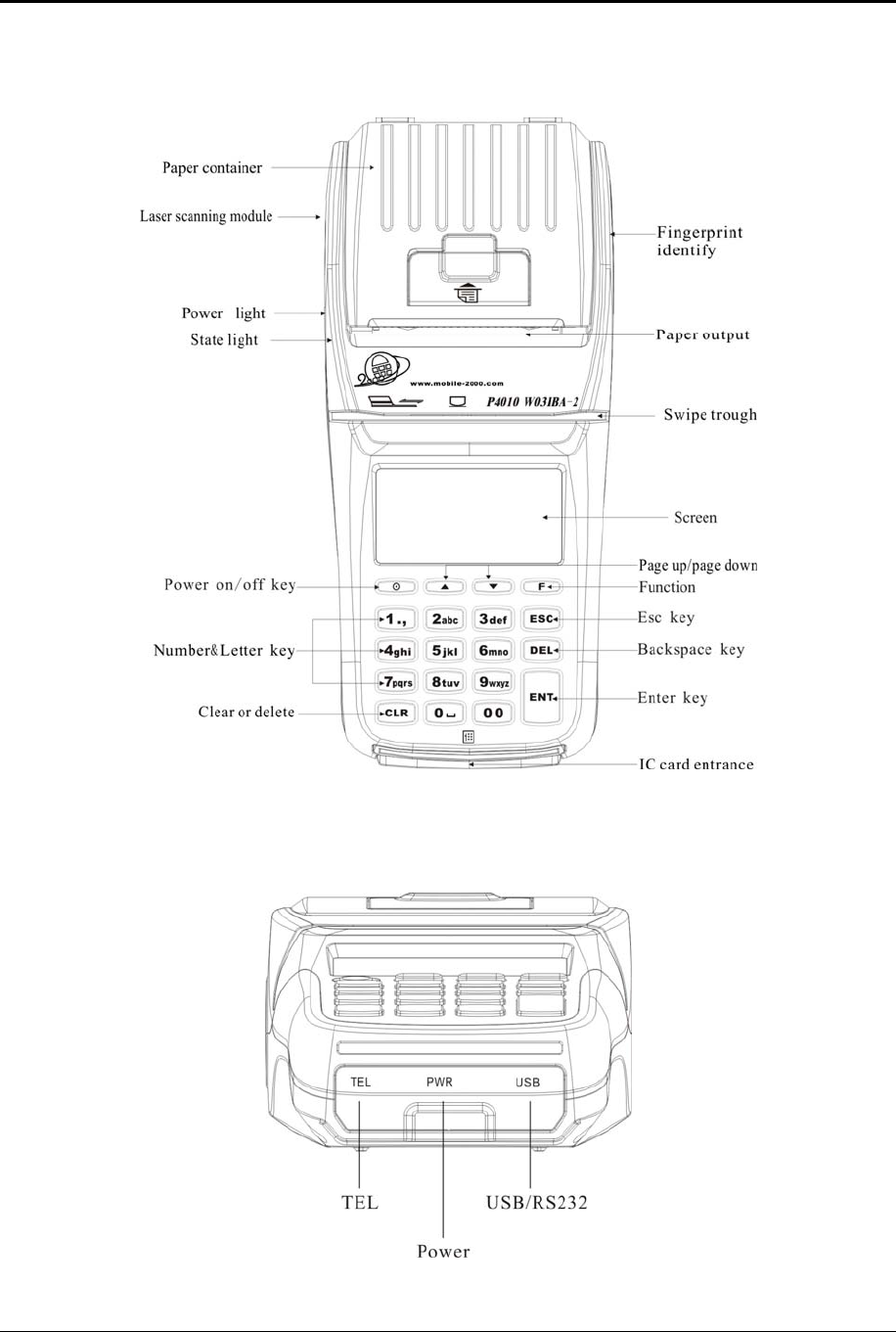
4.0 Terminal Components
4.1 Front View
4.2 Terminal Ports
The figure below shows the ports used to connect the terminal to a power source, telephone line and
various devices such as PIN pads using the multi-port connector.
XD2500 User Guide
© 2009 ExaDigm, Inc. Page 6 of 10 Rev. 5/0609
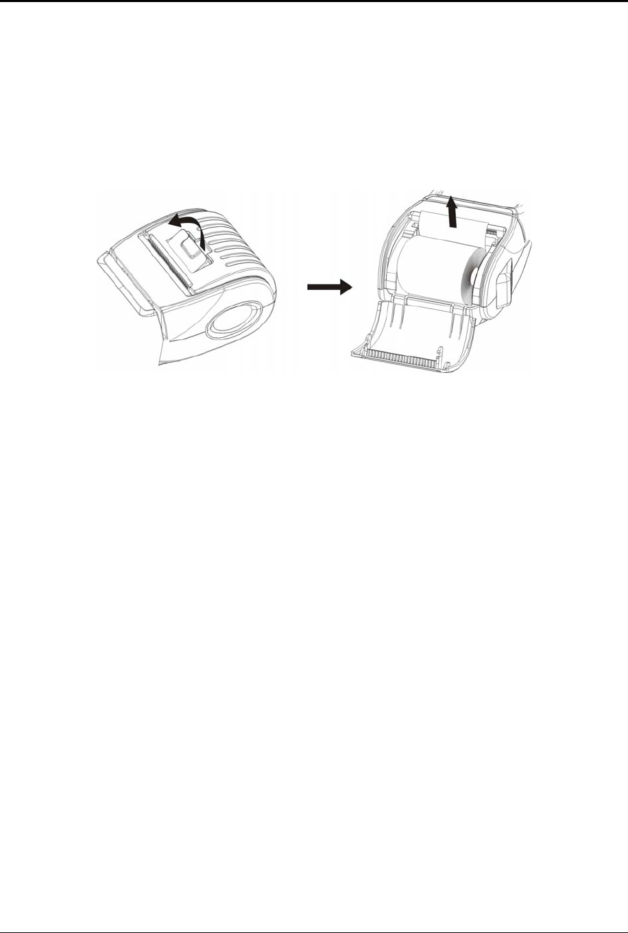
5.0 Installing a Paper Roll
A paper roll is required to print receipts and reports. Follow the steps below to install a paper roll:
1. Place forefinger under flap at top of printer compartment and pull forward using force.
2. Using tab lift compartment up.
3. Place the paper roll in the printer compartment.
4. Close the printer compartment door by pressing until it clicks into place.
6.0 Installing and Removing the Battery Pack
The power pack allows the terminal to operate when not connected to a power outlet. Follow the steps
below to install the terminal’s battery pack.
1. Remove the battery door by placing your finger on the tab and pushing down. While pushing
down pull toward you and slide the door up to remove.
2. Remove the battery by placing a finger on the tab and pulling up. The battery will loosen and slide
to the right, clearing the locking tabs pull the battery out.
3. To install slide the battery under the locking tabs on the left and push down.
4. Replace the battery door by inserting the bottom hedge in first, push down until it snaps into place.
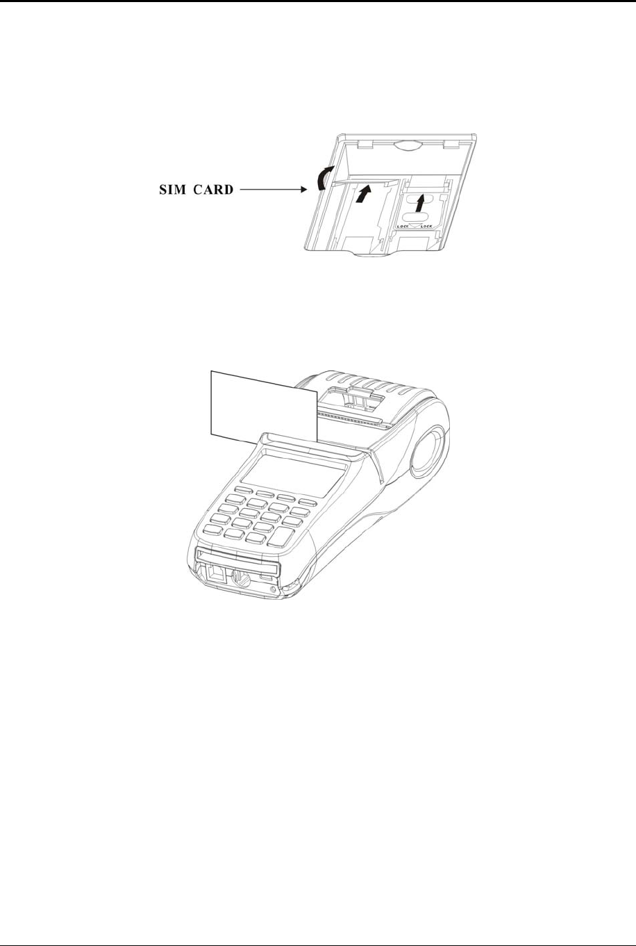
7.0 SIM Chip Installation
Note: SIM chips are only used in GSM modems.
1. The SIM chip slot is located with the terminal face down under the battery compartment. The
battery door must be removed by placing your finger on the tab and pushing down. While pushing
down pull toward you and slide the door up to remove.
2. Remove the battery by placing a finger on the tab and pulling up. The battery will loosen and slide
to the right, clearing the locking tabs pull the battery out.
3. There are two compartments be sure to use the one located on the right. The SIM chip will be
protected by a locking gate.
4. To open the gate, carefully use your fingernail or a small flathead screwdriver to slide the gate
from the LOCKED to the UNLOCKED position (slide down to unlock). The distance required is
about 1/8 inches or 3mm.
5. Once unlocked, use the square slot to open the gate. The gate is on a hinge and should NOT be
removed from the modem.
XD2500 User Guide
© 2009 ExaDigm, Inc. Page 7 of 10 Rev. 5/0609
6. Once the gate is open, the SIM chip can be easily placed into the slot by inserting the card into
the grooves of the holder door. The metallic contact on the SIM card must be placed face down
(toward the contacts on the unit).
7. Close the door by pushing down and slide the gate up to lock it.
8.0 Card Swipe
Swipe card through reader with the magnetic stripe facing down and away from the terminal screen.
9.0 Modem Configurations
Ensure that the terminal is properly connected to an active power source or with a fully charged battery in
it. Carefully plug the AC adapter into the terminal (the plug should insert into the power receptacle on the
lower front side of the terminal) and secure it to a live electrical outlet.
Direct Dial
Ensure that the telephone cord is connected to the RJ11 port located on the lower front side of the
terminal. Plug the other end of the telephone cored into the telephone jack on the wall. For better
communication Dial using a TCIP connection (digital) is recommended.
CDMA
Before you use the terminal to do live transactions with TCP/IP connections, you need to make sure the
modem is activated. Contact your network carrier, ISO or ExaDigm to confirm activation.
XD2500 User Guide
© 2009 ExaDigm, Inc. Page 8 of 10 Rev. 5/0609
GSM/GPRS
Before you use the terminal to do live transactions with TCP/IP connections, you need to make sure the
modem is activated by inserting the SIM card. Contact your network carrier, ISO or ExaDigm to confirm
activation.
10.0 Connecting External Readers
The multi-purpose USB port allows various devices to be attached and used. Attach the multi-purpose
attachment to the R232 port located on the lower front side of the terminal.
11.0 Alpha/Numeric Keypad
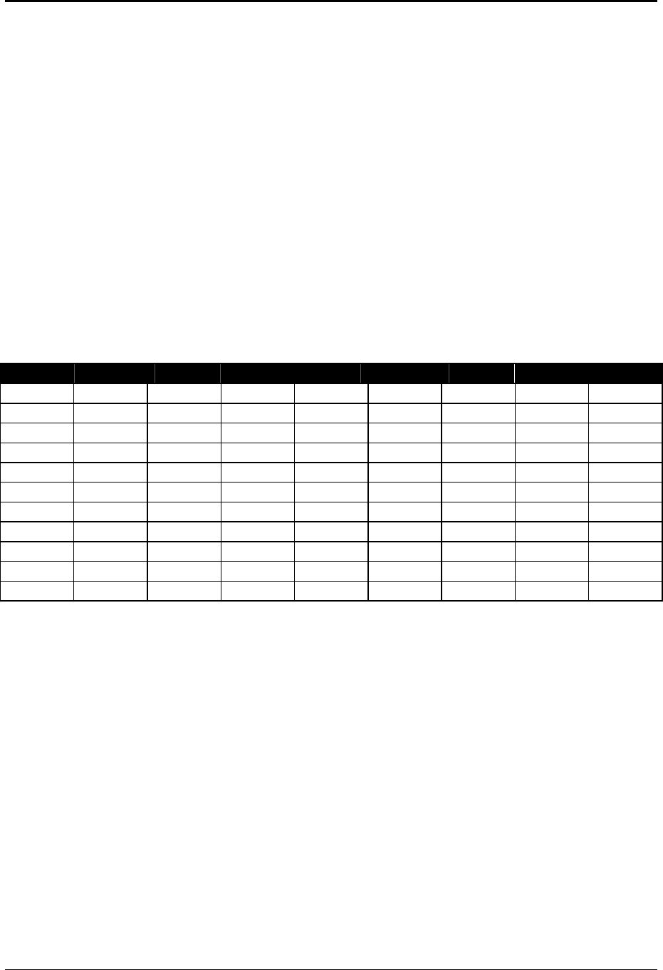
The keypad contains horizontal rows of numeric keys with alphabetic characters. The keypad accepts
numeric keys as the default. To activate the alphabetic keys, continue to press the numeric key to change
from a numeric digit to an alpha character. The following is a table representing the Numbers, Alpha
Letters and Symbols on the keypad.
Number 1 2 3 4 5 6 7 8
1 . , z .
2 A B C a b c
3 D E F d e f
4 G H I g h i
5 J K L j k l
6 M N O m n o
7 P Q R S p q r s
8 T U V t u v
9 W X Y Z w x y z
0 SPACE
00
For example press the numeric key [2], then press the [2] key again until the desired alpha character
displays. Press once to display the alpha letter A (capital), press twice to display the alpha letter B
(capital), and press four times for the alpha letter a (lower case) to display.
12.0 Color-Coded Keys
The color-coded keys perform the following tasks:
Red CANCEL Key: Press the red key to cancel the current operation or return to the
previous menu.
Yellow CLEAR and Backspace Key: Press this key to backspace, erasing typed text,
starting from right to left or to clear an action.
Green ENTER Key: This key is used like the ENTER key on a computer keyboard. Press
the green key to signify to the terminal that the task is complete, or press to enable a function
or perform an action based on typed data.
Blue FUNCTION Key: This key is used activate a special function and to enter alpha
characters from the keyboard.

XD2500 User Guide
© 2009 ExaDigm, Inc. Page 9 of 10 Rev. 5/0609
13.0 Terminal Indicators
Indicators are located on the display screen and will display when the mentioned peripheral or device is
attached.
External Power Supply
Battery
Charge strength
Charging continuously flickers while charging
Fully charged
Radio
GPRS
CDMA
Signal strength
14.0 Battery and Charger Safety
Proper battery and charger safety is necessary to ensure the terminal will perform to its potential and
reduce the risk of overheating, igniting or explosion, resulting in serious bodily harm or property damage.
Do not disassemble, open, crush, bend, deform, puncture, shred or attempt to modify the battery
or charger.
Do not modify or remanufacture, attempt to insert foreign objects into the battery or charger,
immerse or expose to water or other liquids, or expose to fire, explosion, or other hazards.
Only use the battery and charger for the terminal for which it was specified.
Only use the battery with a charging system that has been qualified with the unit. Use of an
unqualified battery or charger may present a risk of fire, explosion, leakage or other hazard.
Do not short circuit a battery or allow metallic or conductive objects to contact the battery
terminals.
Replace the battery only with another battery that has been qualified with the unit. Use of an
unqualified battery may present a risk of fire, explosion, leakage, or other hazard.
Promptly dispose of used batteries in accordance with local regulations.
Children should not touch battery and charger.
Avoid dropping the battery and charger. If the battery or charger is dropped, especially on a hard
surface, and the user suspects damage, contact ExaDigm for inspection.
Improper battery or charger use may result in a fire, explosion, or other hazard.
The working environment temperature is 0-50 degree.
CAUTION: To reduce the risk of fire use only No.26 AWG or larger telecommunication line cord.

XD2500 User Guide
© 2009 ExaDigm, Inc. Page 10 of 10 Rev. 5/0609
RF exposure information:
The SAR limit of USA (FCC) is 1.6 W/kg averaged over one gram of tissue. Device types XD2500 (FCC
ID: XDQ2500EXA) has also been tested against this SAR limit. The highest SAR value reported under
this standard during product certification when properly worn on the body is 0.228 W/kg. This device was
tested for typical body-worn operations with the back of the handset kept 1.5cm from the body. To
maintain compliance with FCC RF exposure requirements, use accessories that maintain a 1.5cm
separation distance between the user's body and the back of the handset. The use of belt clips, holsters
and similar accessories should not contain metallic components in its assembly. The use of accessories
that do not satisfy these requirements may not comply with FCC RF exposure requirements, and should
be avoided.
This device complies with part 15 of the FCC rules. Operation is subject to the following two conditions: (1)
this device may not cause harmful interference, and (2) this device must accept any interference received,
including interference that may cause undesired operation.
NOTE: The manufacturer is not responsible for any radio or TV interference caused by unauthorized
modifications to this equipment. Such modifications could void the user’s authority to operate the
equipment.