Xingyaohua T7AH-2400 Radio User Manual
Shenzhen Xingyaohua Industrial Co., Ltd. Radio
User Manual
Tel:+86(755)84008148 +86(755)84673906
Fax:+86(755)84673903
Address:NO.28 Wenxin Road, Xinmu Lao Village,
Pinghu Town,Longgang District,Shenzhen City,
Guangdong Province,518111 China
Website:www.zdracing.com
SHENZHEN XINGYAOHUAINDUSTRIALCO.,LTD
T7AH-2400
T7AH-2400
T7AH-2400

Safety and attention matters
* To make your remote control equipment can make model correct and work
safety, please read this manual carefully,and use it strictly with the
instructions in the future.
* Reminder
1. Tt can only be used as the control to the model.
2. The use of the product should conform to the relative law and local
regulations.
3. It is out of warranty such as man-made damage, replace components and
adjust it inside the machine subjectively.
4. This manual may change without notice. If you find a need to modify and
add in manual, please contact us.
* check the battery before turning on transmitter, ensure that the battery
power is adequate. The voltage of the transmitter's battery cannot be
under 8.6V.
* Don't let the antenna contact with any object when transmitter working.
The more don't touch the antenna.
* Please check the working voltage of the receiver before use. The voltage
shall not be less than 4 V.
* Please check whether servo system is normal before using the remoter.
Be sure each control action of the transmitter is done correctly.
* To keep the remote control equipment away from moisture and high
temperature, not to vibrate it hardly and clean it with chemical liquefacient.
* To keep the product and its accessories away from children .
* We will not responsible for any accident and loss caused by personal
instruction violated law and local regulation on radio management.
T7AH-2400 instruction manual
1
Catalogue
One Summarize
Second、 Characteristics
Three、 The machine configuration
Four、 The binding transmitter and receiver
Five、R7AH-2400 wireless simulator function
Six、 the RC lever the strength of the regulation
Seven、input method
7.1、 input panel and keys function
7.2、 input mode and function selection
Eigh、two example of quickly start the plane
Nine、 fixed wing aircraft programming guide
9.1、 system model function
9.2 、system model flow chart
9.3、 function mode flow chart
Ten、Helicopter programming guide 67 page
10.1 system installation mode installation
10.2 function mode, pp. 81 flow chart
10.3 function mode function
11、related safety matters
、
2
11
6
8
38
40
49
52
65
13
14
23
6
7
34
Summarize
T7AH-2400 is a style of RC equipments that can be used for fixed wing aircraft also
can be used for helicopters model aircraft.It use the 2.4 GHz frequency-hopping
spread spectrum radio system, tell the replacement of the remote control
equipment crystal trouble,you won't have to worry about interference cause by the
remote control equipment of the same frequency. This type of remote control also
can restassured be used in large oil power plane,because the receiver of it can
resist almost all of electromagnetic interference in the air.
The transmitter main performance indicators
Work power: 8 nimh battery charge section
Working current: <
Launch frequency: 2400 MHz (FHSS)
Channel number: 7
Function set instructions way: LCD
Receiver main performance indicators
Work power: 4.8 V-6
Receive frequency: 2400 MHz
Channel number: 7 + PPM signal channel
Second, Characteristics
●7 channel steering gear had function
●With the helicopter and fixed wing two kind of control mode and free switch when
starting up.
●A memory of various models' parameter settings of 8 kinds of fixed wings and 8
kinds of helicopters flight respective.
●Wireless simulator funtion can be used to directly output simulator's signal to
computer.
●Wireless trainer function can prevent the user from the trouble connecting the
trainer line.
●The way of receiving code can easily finish matching between transmitter and
receiver.
●A transmitter can match with more than one of receivers's codes.
●Transmitters can work at same time without any special set. They wouldn't be
interfered with each other.
●The receiver's antenna horizontal polarization and vertical polarization double
receive complementary system
Three, the machine configuration
A T7AH-2400 transmitter
A R7AH-2400 a receiver
Four pcs DJ 200 servo
Transmitter battery
Receiver battery
Special charger
Four, the binding transmitter and receiver
◆the code of thehost and receiver
he transmitter can and two different receiver supporting the use of the R7AH
-2400 and R7AH-2400 A. The type 2400 have antenna with Double channel
receiver function. the vertical and horizon plate form are more sensitive,
and with wireless trainer function Function of code as follows:.
◆Using receiver with trainer fuction to code
R7AH 2400 receiver with wirless trainer function can use any transmitter as trainer,
another one transmitter as student machine. Student machine should code with the
trainer R7AH 2400 receiver , then the students transmitter can be used. The method
is shut down power of the trainer, while open the student transmitter's and connect
with receiver transmitter power, press the S-code switch untill the green S-LED
indication go solid
Note: There couldn't have other 7 TAH-2400 in the receiver's received signal range
when coding, or not success
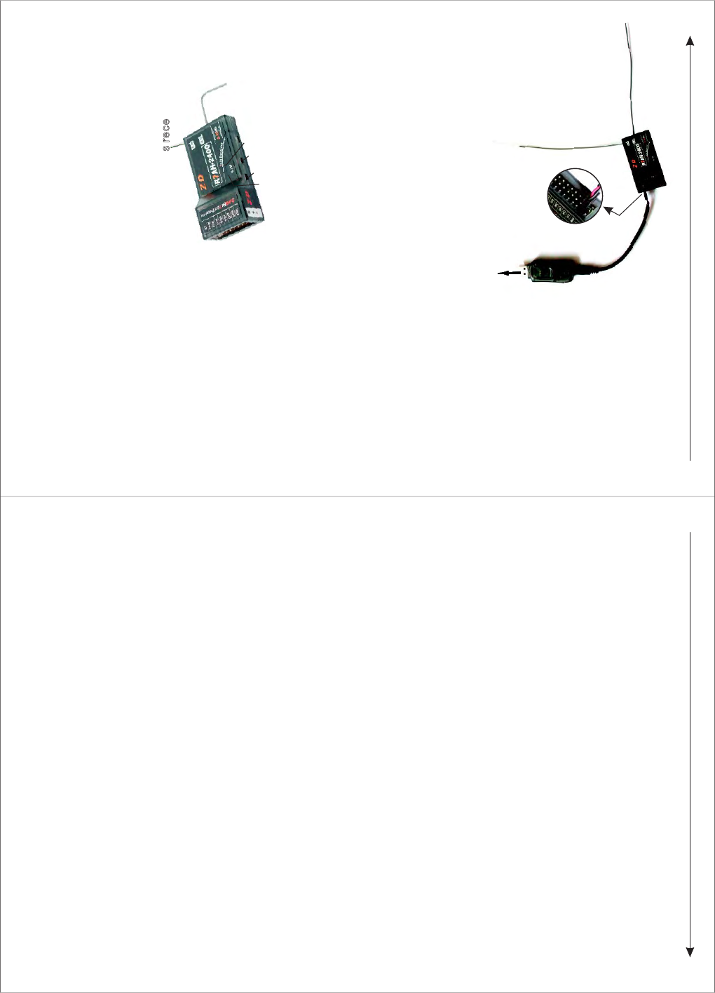
Five, R7AH-2400 wireless simulator function
Connecting a computer USB outlet
The second
plug-in of pins
from the
front view
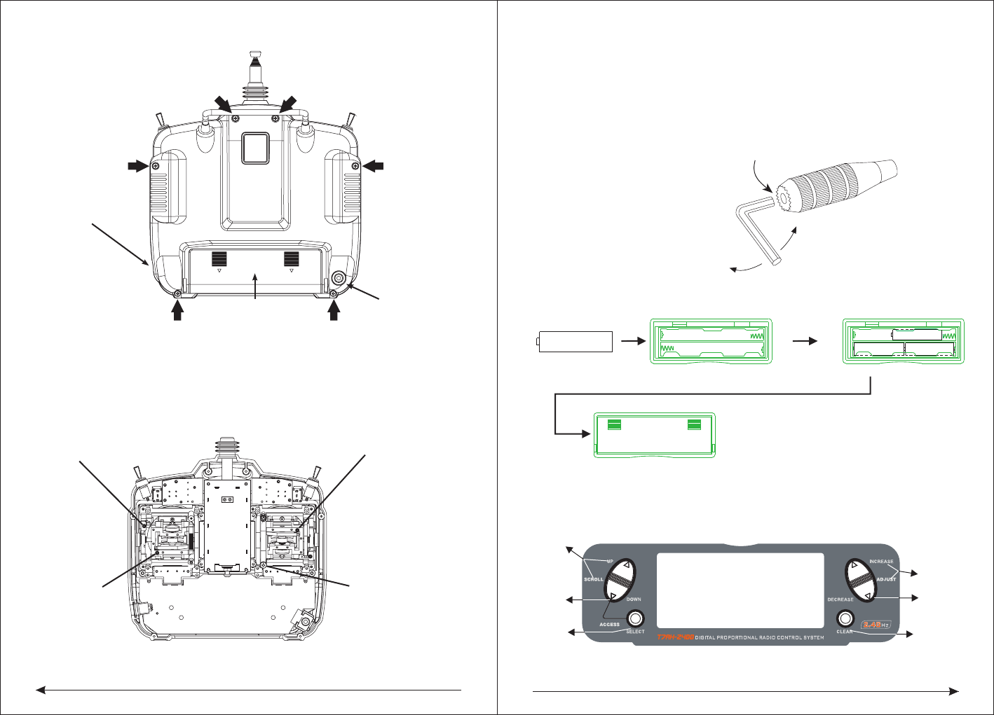
Six, control stick tension adjustment
◆Remoting the screws of the back of the RC
R7AH-2400 PPM channel can use special set of plugs line connection with
simulator decoder. Then insert the decoder into the computer USB mouth, use
transmitter can complete wireless simulator function.
C
C
o
o
n
n
n
n
e
e
c
c
t
t
t
t
r
r
a
a
n
n
s
s
m
m
i
i
t
t
t
t
e
e
r
r
a
a
n
n
d
d
r
r
e
e
c
c
e
e
i
i
v
v
e
e
r
r
'
'
s
s
p
p
o
o
w
w
e
e
r
r
,
,
f
f
i
i
r
r
s
s
t
t
l
l
y
y
,
,
p
p
r
r
e
e
s
s
s
s
t
t
h
h
e
e
M
M
c
c
o
o
d
d
e
e
s
s
w
w
i
i
t
t
c
c
h
h
o
o
f
f
r
r
e
e
c
c
e
e
i
i
v
v
e
e
r
r
t
t
i
i
l
l
l
l
t
t
h
h
e
e
M
M
-
-
L
L
E
E
D
D
i
i
n
n
d
d
i
i
c
c
a
a
t
t
o
o
r
r
l
l
i
i
g
g
h
h
t
t
c
c
h
h
a
a
n
n
g
g
e
e
s
s
f
f
r
r
o
o
m
m
f
f
l
l
i
i
c
c
k
k
e
e
r
r
i
i
n
n
g
g
i
i
n
n
t
t
o
o
l
l
i
i
g
g
h
h
t
t
i
i
n
n
g
g
.
.
T
T
h
h
e
e
n
n
,
,
p
p
r
r
e
e
s
s
s
s
t
t
h
h
e
e
S
S
c
c
o
o
d
d
e
e
s
s
w
w
i
i
t
t
c
c
h
h
t
t
i
i
l
l
l
l
t
t
h
h
e
e
S
S
-
-
L
L
E
E
D
D
i
i
n
n
d
d
i
i
c
c
a
a
t
t
o
o
r
r
l
l
i
i
g
g
h
h
t
t
c
c
h
h
a
a
n
n
g
g
e
e
s
s
f
f
r
r
o
o
m
m
f
f
l
l
i
i
c
c
k
k
e
e
r
r
i
i
n
n
g
g
i
i
n
n
t
t
o
o
l
l
i
i
g
g
h
h
t
t
i
i
n
n
g
g
,
,
s
s
h
h
o
o
w
w
s
s
t
t
h
h
a
a
t
t
t
t
r
r
a
a
n
n
s
s
m
m
i
i
t
t
t
t
e
e
r
r
a
a
n
n
d
d
r
r
e
e
c
c
e
e
i
i
v
v
e
e
r
r
c
c
o
o
d
d
e
e
s
s
u
u
c
c
c
c
e
e
s
s
s
s
.
.
T
T
h
h
e
e
m
m
o
o
d
d
e
e
l
l
2
2
4
4
0
0
0
0
A
A
i
i
s
s
s
s
i
i
n
n
g
g
l
l
e
e
r
r
e
e
c
c
e
e
i
i
v
v
e
e
d
d
c
c
h
h
a
a
n
n
n
n
e
e
l
l
w
w
i
i
t
t
h
h
w
w
i
i
r
r
e
e
l
l
e
e
s
s
s
s
t
t
r
r
a
a
i
i
n
n
e
e
r
r
f
f
u
u
n
n
c
c
t
t
i
i
o
o
n
n
,
,
o
o
n
n
l
l
y
y
o
o
n
n
e
e
c
c
o
o
d
d
e
e
s
s
w
w
i
i
t
t
c
c
h
h
a
a
n
n
d
d
a
a
i
i
n
n
d
d
i
i
c
c
a
a
t
t
o
o
r
r
l
l
i
i
g
g
h
h
t
t
,
,
t
t
h
h
e
e
w
w
a
a
y
y
t
t
o
o
c
c
o
o
d
d
e
e
i
i
s
s
s
s
a
a
m
m
e
e
w
w
i
i
t
t
h
h
2
2
4
4
0
0
0
0
t
t
y
y
p
p
e
e
,
,
o
o
n
n
l
l
y
y
c
c
o
o
d
d
i
i
n
n
g
g
t
t
h
h
e
e
s
s
i
i
n
n
g
g
l
l
e
e
y
y
a
a
r
r
d
d
s
s
.
.
N
N
o
o
t
t
e
e
:
:
T
T
h
h
e
e
r
r
e
e
c
c
o
o
u
u
l
l
d
d
n
n
'
'
t
t
h
h
a
a
v
v
e
e
o
o
t
t
h
h
e
e
r
r
7
7
T
T
A
A
H
H
-
-
2
2
4
4
0
0
0
0
i
i
n
n
t
t
h
h
e
e
r
r
e
e
c
c
e
e
i
i
v
v
e
e
r
r
'
'
s recei
i
v
v
e
e
d
d
s
s
i
i
g
g
n
n
a
a
l
l
r
r
a
a
n
n
g
g
e
e
w
w
h
h
e
e
n
n
c
c
o
o
d
d
i
i
n
n
g
g
,
,
o
o
r
r
n
n
o
o
t
t
s
s
u
u
c
c
c
c
e
e
s
s
s
s
.
.
S-LED indicator light
Scode switch
Mcode switch
M-LED indicator light
56
LOOSEN
TIGHTEN
SETSCREW
CHARGING JACK FOR
NI-CD BATTERY
BATTER Y COVER TRAINER JACK
◆Should adjust lever tension
Note: Remove the six transmitter back cover screws. Carefully open the transmitter
back and don't cause damage to any components.
Adjust the tension of every lever's screw to desired degree ( turn the screws counter
-clockwise can loosen tension, then turn screws clockwise can tighten tension)
ELEVATOR TENSION
SCREW
AILERON TENSION
SCREW
RUDDER TENSION
SCREW
THROTTLE TENSION
SCREW
◆Control stick length adjustment
The 7 TAH-2400 allows you to adjust the control stick's length. Use the 2mm Allen
wrench,
turn the wrench counterclockwise to loosen the crew. Then, turn the stick clockwise
to shorten or counterclockwise to lengthen. After the control stick length has been
adjusted to suitable height, tighten the 2mm setscrew.
◆battery and battery change
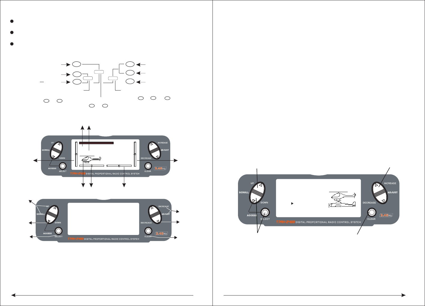
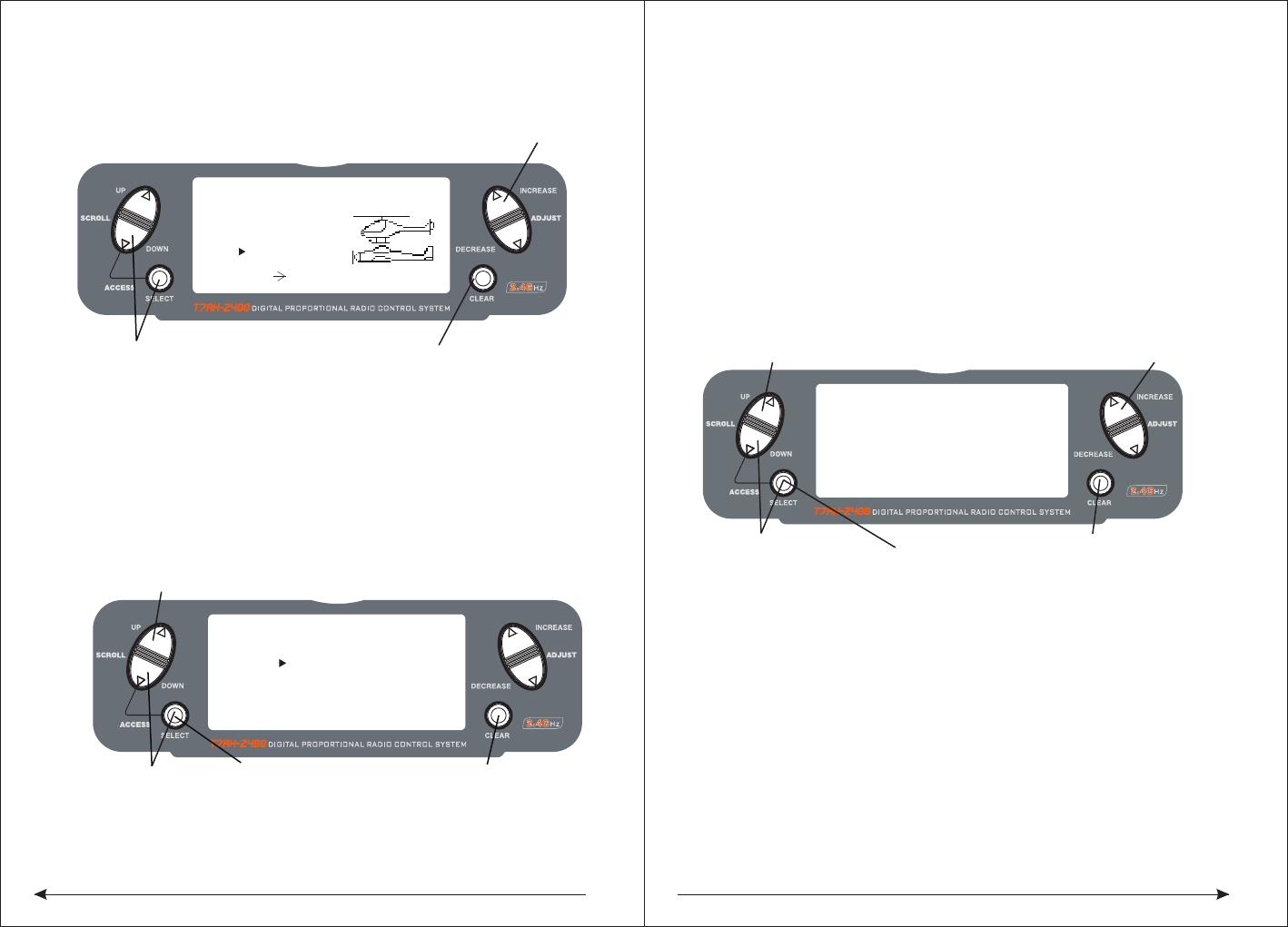
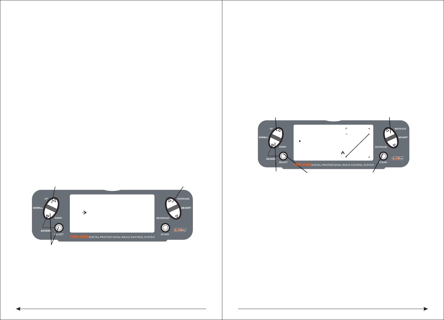
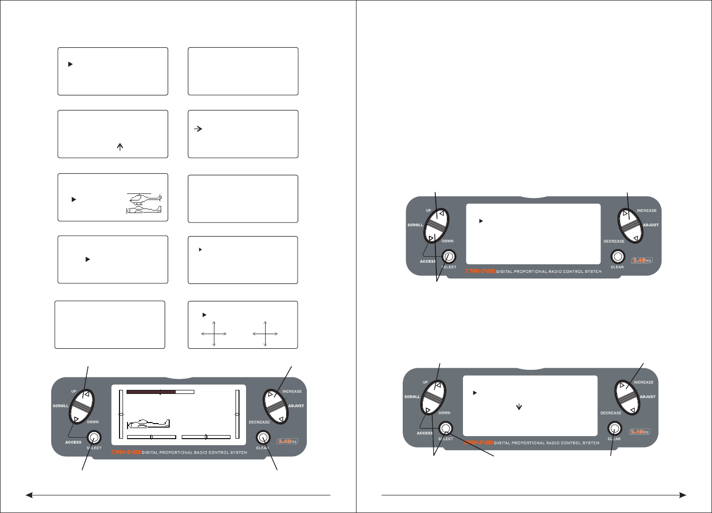
Seven, inputing method
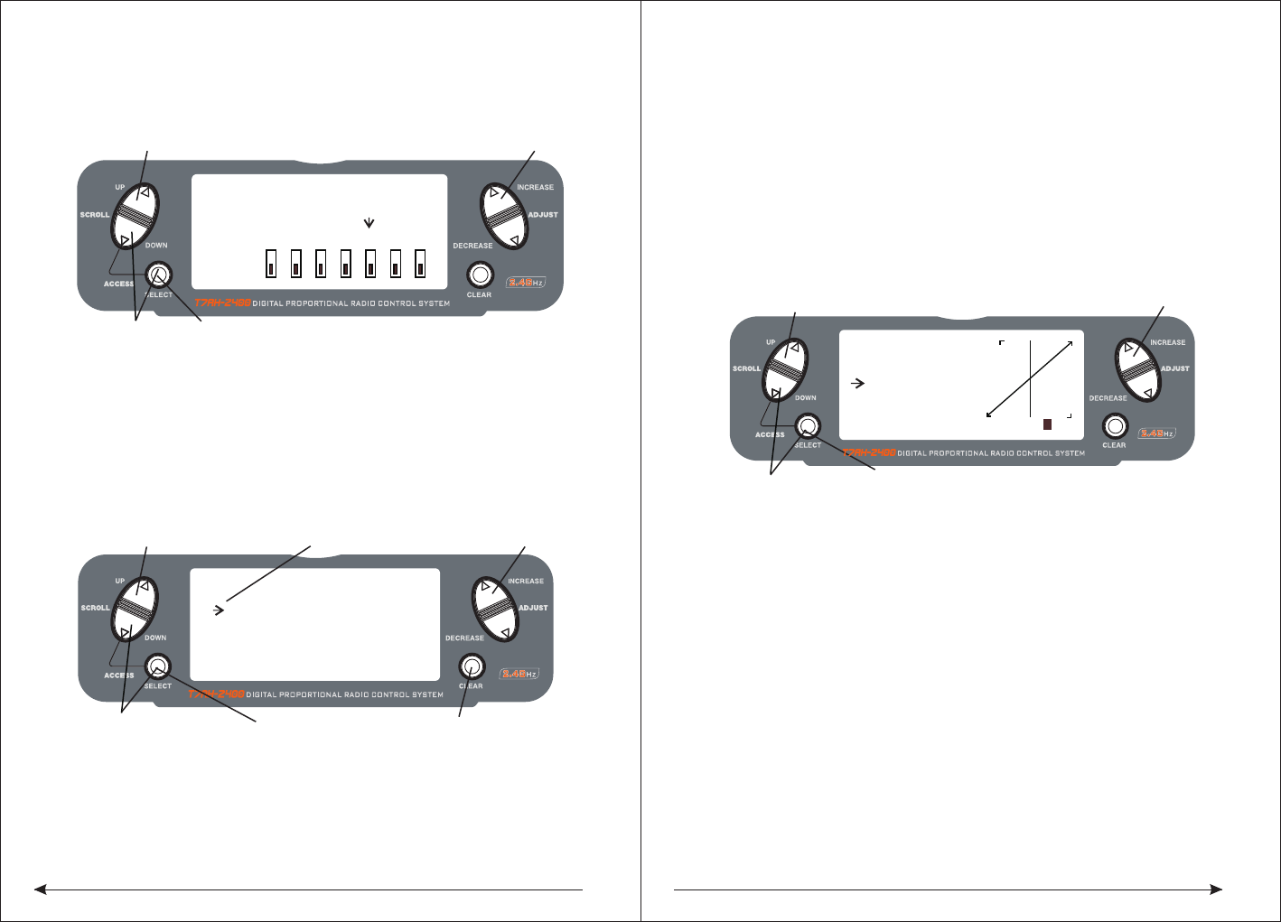
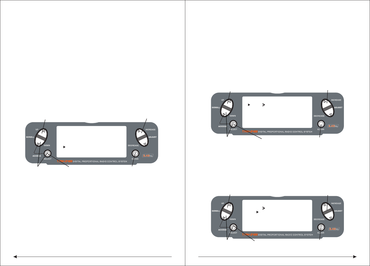
7.1Input panel and keys function
SCROLL UP
DOWN
SELECT
ADJUST
INCREASE
ADJUST
DECREASE
CLEAR
AA AA
AAAA
78
Input key and scroll under the condition of input, all will make a sound to
confirm the correct.
Add keys and Decrease keys have rapidly increasing or decreasing function
(continuous pressure which will rapidly increasing or decreasing)
Sometimes occur numerical unchanged, but have the confirmed sound,
that is because of the numerical value in the decimal point,no suggested
in the LCD screen, but the internal value have changed.
Available when
to select function
available when to
select setted project
{
}
up key
down key
UP
DN
select key SEL
ENTER
LIST
Alert mode switch
DNSEL
(press with simultaneously)list
CO NT
+
-
SEL
Change screen light and shade
increase key
decrease key
clear key
available when to
set the information
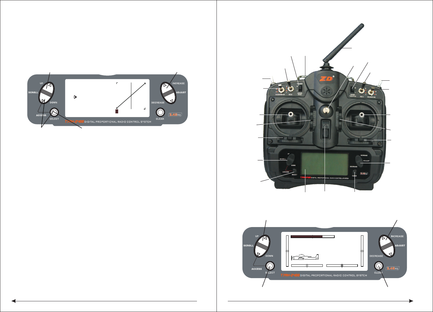
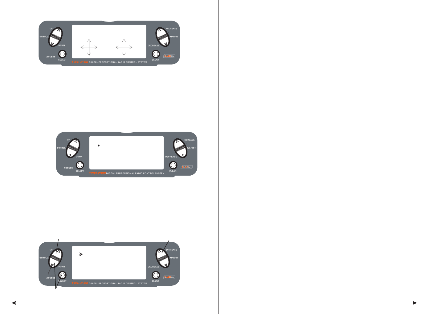
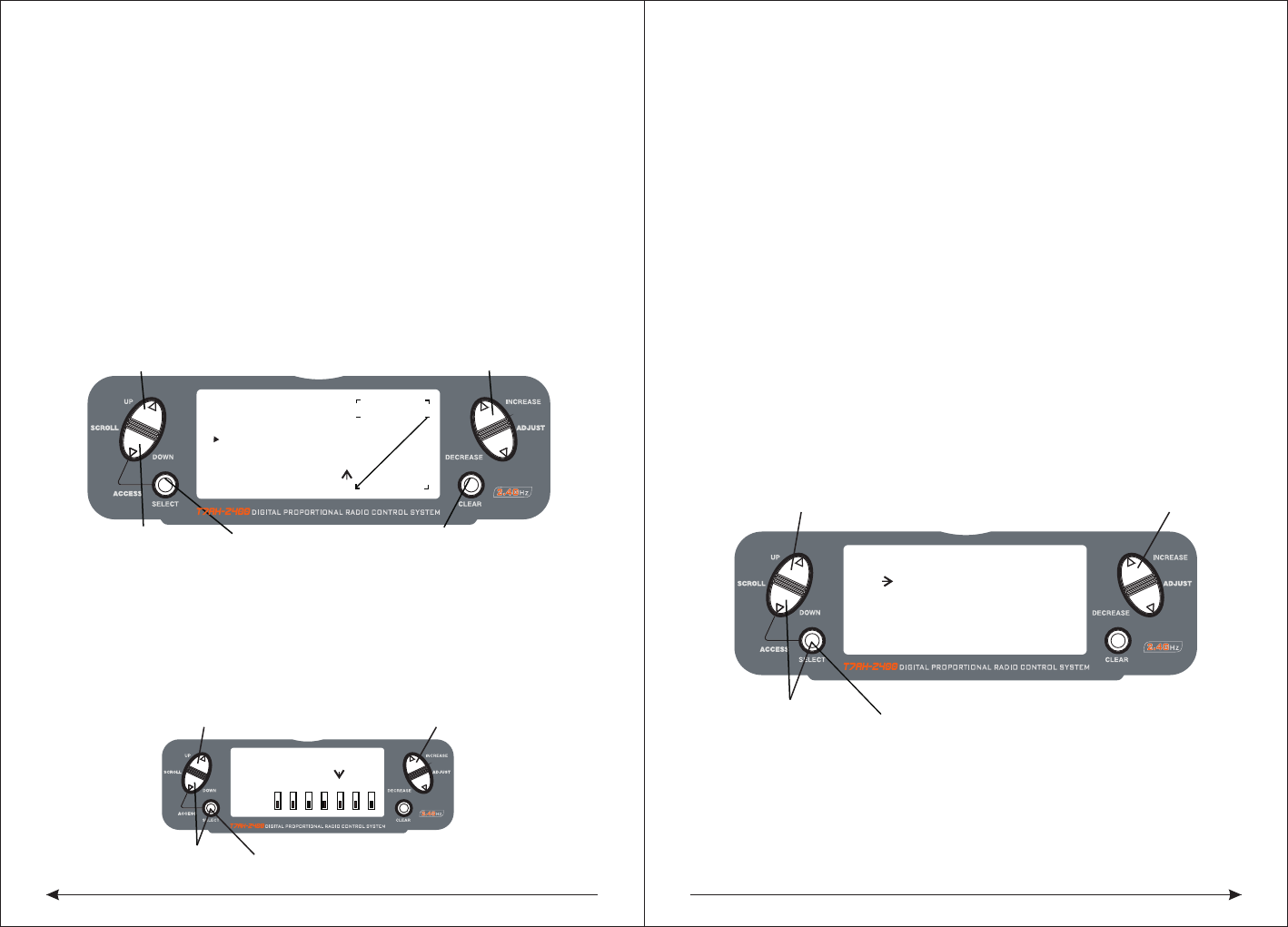
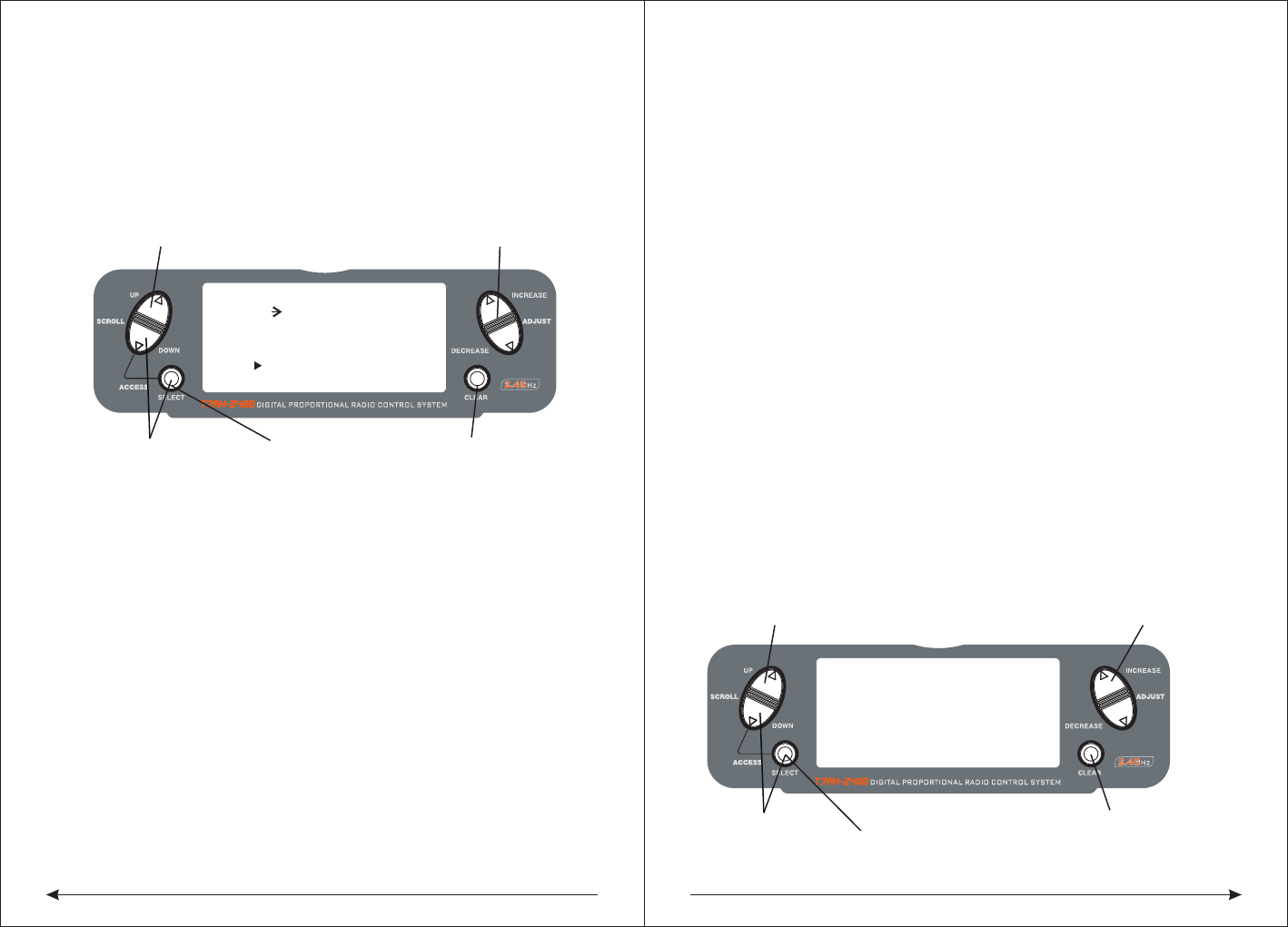
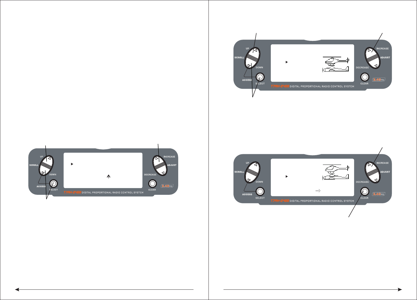
7.2 Inputing mode and function selection
Boot screen
S
as described below:
SCROLL UP and SCROLL DOWN, the two keys used to flip menus. The SELECT is
select key, used to select the menu, ADJUST INCREASE and ADJUST DECREAS
are used to change the specific settled date under the options. CLEAR is reseted
button, make the date to reset the default values.
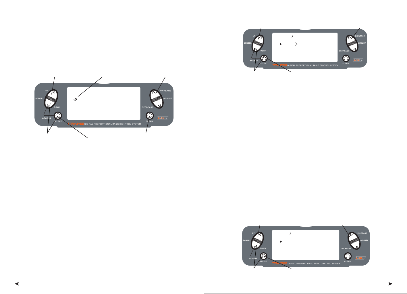
In additon, these keys has some combination setting functions:
1 In the boot screen, pressing SCROLL DOWN and the SELECT keys
simultaneously, you can enter the system setup menu interface, in this display
interface, pressing the SCROLL UP and SELECT keys, you can enter the system
setup menu list interface. At the same time in SCROLL DOWN and SELECT keys
,you can return to the system setup menu interface, once again, then you can
return to the main display interface.
2, After startup, pressing SCROLL DOWN and SELECT keys simultaneously, you
can enter the function setup menu interface, pressing SCROLL UP and SELECT
buttons, you can enter the function setting menu list. When in the interface, you
can press SCROLL DOWN and SELECT keys simultaneously, exist to function
setup menu interface, then press again, go back to the main display interface.
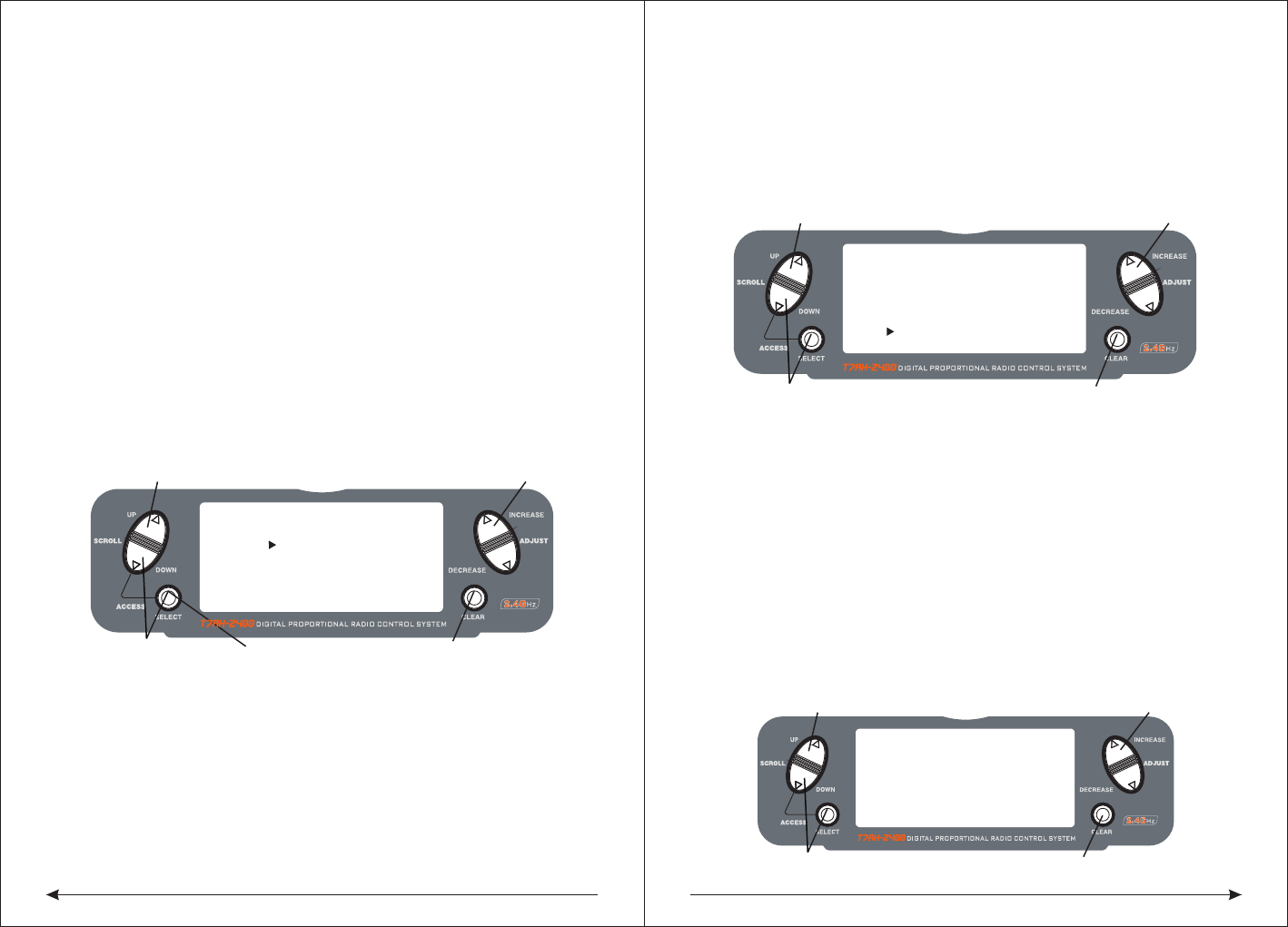
DECREASE、CLEAR, The specific function of this several LCD operation buttons
The text below the key panel figure state:
Panel SCROLL UP、SCROLL DOWN、SELECT、ADJUST INCREASE、ADJUST
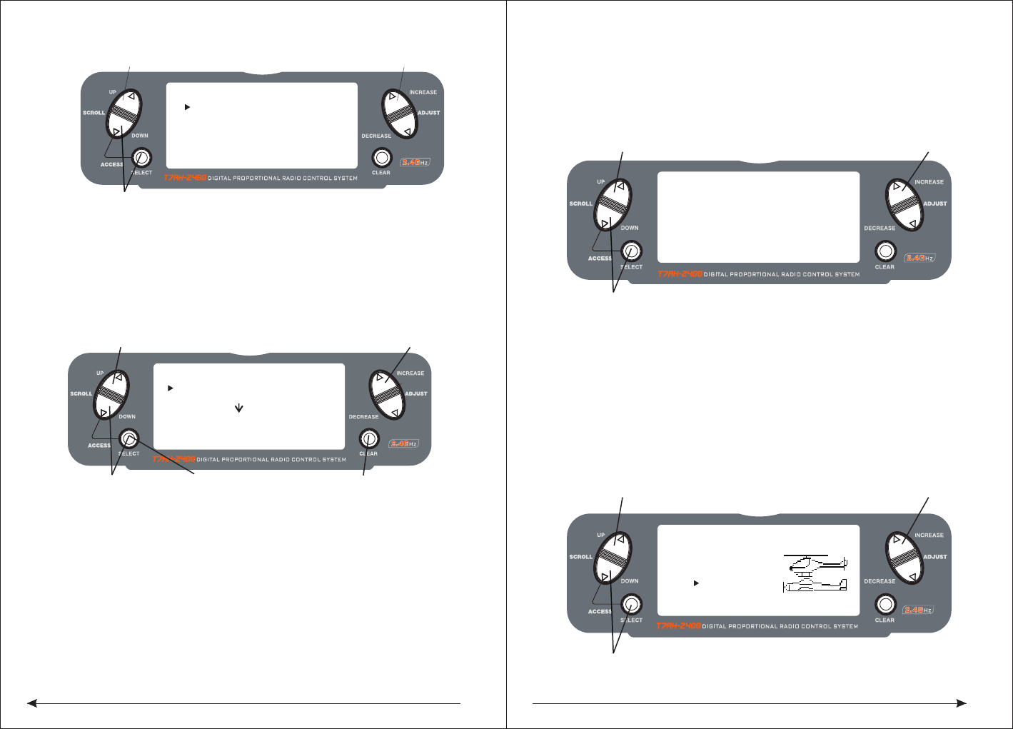
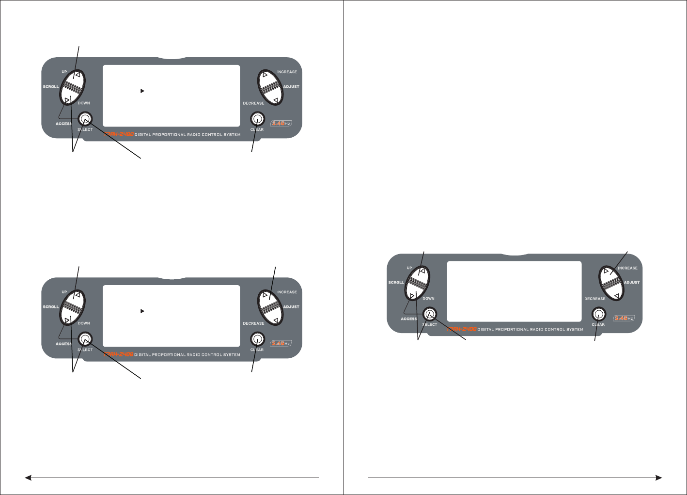
Eight, aircraft quick setup guide
◇choose aircraft type
Turn the power and press DOWN and SELECT keys simultaneously, the RC turns
into the system setup mode.
Press the UP or DOWN key until TYPE SELECT appears on the screen.
According to the UP or DOWN until the SELECT button, by appear on the screen.
Press INCREASE or DECREASE key, the black triangle towards or in "HELI" and
◆Servo Reversing
Press to enter TYPE SELECT
[TYPE SELECT]
MODEL 1
HELI
INCREASE and DECREASE key
Hold while turning on transmitter
ACRO
Accept new model type CHANNGE
SCROLL UP
DOWN
SELECT
ADJUST
INCREASE
ADJUST
DECREASE
CLEAR
MODEL 0 HELI0001
12.5ms FRAME RATE
10.3V
Model number Launch control data update cycle
Current control the plane type
Throttle fine
-tuning quantity
display
Rudder fine-tuning
quantity display Aileron fine-tuning quantity display
Elevator fine-
tuning quantity
display
UP
SEL
(press with simultaneously)
SEL +-
(press with simultaneously)with
910
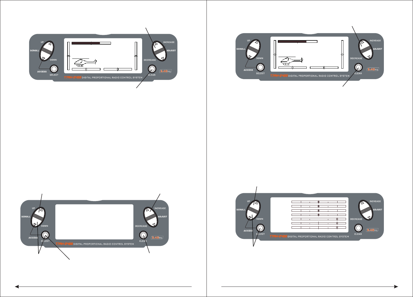
◇To Access Servo Reversing
Turn the power on and press the DOWN and SELECT keys simultaneously to enter
the function mode.
Press the UP and DOWN keys until REVERSING SW appears on the screen.
Press the SELECT key to select the desired channel, and then press the INCREASE
or DECREASE key reverse or normal servo direction.
◆Travel Asjustment
Insert English instruction 26 page below
◇To Access Travel Adjustment
Turn on the power and press the DOWN and SELECT keys to enter into the function
model press the UP or DOWN key until TRAVEL ADJUST appears on the screen.
Press selected key to move cursor arrow to the desired channel.
Note: if your aircraft flaps is controlled by two independent servos, please see page
44. The rear wing type for selected explicitly pointed out the programming
flaperon.
◆Only aircraft adjust for HELI, just have this feature setup.
T7AH-2400 offers four independent pitch curves, each with up to five adjustable
points. This function allocates a separate pitch curve setting during normal, stunt
1, stunt 2 and hold modes. Once the pitch curves are adjusted, each can be
activated in flight using the three-position flight mode and throttle hold switches.
Each of the five points of the pitch curve are independently adjustable from 0–
100%. These five points correspond to low, 25%, mid, 75% and high stick positions.
See Page 94 for more details on setting up pitch curves.
◇To Access the Pitch Curve Function
Turn the power on and press the DowN and SELECT keys simultaneously to enter
the function mode.
Press the UP or DOWN key until PITCH CURVE NORM appears on the screen.
Press the SELECT key to select the stick position that you wish to adjust the pitch.
● L = Low
● 1 = 25%
● 2 = 50%
● 3 = 75%
● H = High
Press the INCREASE or DECREASE key to adjust the pitch position.
Recommended Initial Pitch Settings
● L= -4º
● 2= 5º
● H= 9º
Note: For more information about setting up pitch curves, see continue pages.
◆Adjust the three sections of switch with corresponding normal model under the
throttle curve Only aircraft adjust for HELI, just have this setup function.
[REVERSING SW]
GEAR
Press to select REV. or NORMPress to enter REVERSE
Press to enter
Function Mode
Press to select
desired channel
NORM
ch 1 2 3 4 5 6 7
REV.
[TRAVEL ADJUST]
THRO
H 100%
L 100%
ELEV
D 100%
U 100%
AILE
L 100%
R 100%
RUDD
L 100%
R 100%
Selected channel
Press to enter
TRAVEL ADJUST
Press to enter
Function Mode
Press to return
value to default
Press to select
desired channel
Press to adjust value
[PITCH CURVE]
Point-3
51 51
INH
1 2 3HL
IN
Press to enter
PITCH CURVE
Press to enter
Function Mode
Press to select
desired points
Press to change
OUT
NORM
"ACRO" appear alternately, if not show "the YES-> CLEAR KEY, it means the
current plane is the type, if not be, it means you can choose the aircraft type by
pressing CLEAR key.
11
Adjustment of the throttle curves is similar to the pitch curve adjustment described
on the preceding page. Three throttle curves are available: normal, st1 and st2.
All throttle curves have five adjustable points—low, 25%, 50%, 75% and high.
Flight modes are located on the 3-position flight mode switch. The throttle curve is
in the normal mode when the Flight Mode switch is in the rear position and the
Throttle Hold switch is rearward
◇To Access the Throttle Curve Function
Turn the power on and press the DOWN and SELECT keys simultaneously to enter
the function mode.
Press the UP or DOWN key until THROTTLE CURVE NORM appears on screen.
Press the SELECT key to select the stick position that you wish to adjust the throttle.
● L= Low
● 1= 25%
● 2= 50%
● 3= 75%
● H= High
Press the INCREASE or DECREASE key to adjust the throttle value of the selected
throttle position.
For more information about setting up Throttle Curves see continue pages. For
additional features like Dual Rates and Mixing etc, see the appropriate pages
listed in the table of contents. The more detail information about the HEI mode,
please see the HEL part of this book.
NINE, Aircraft Programming guide
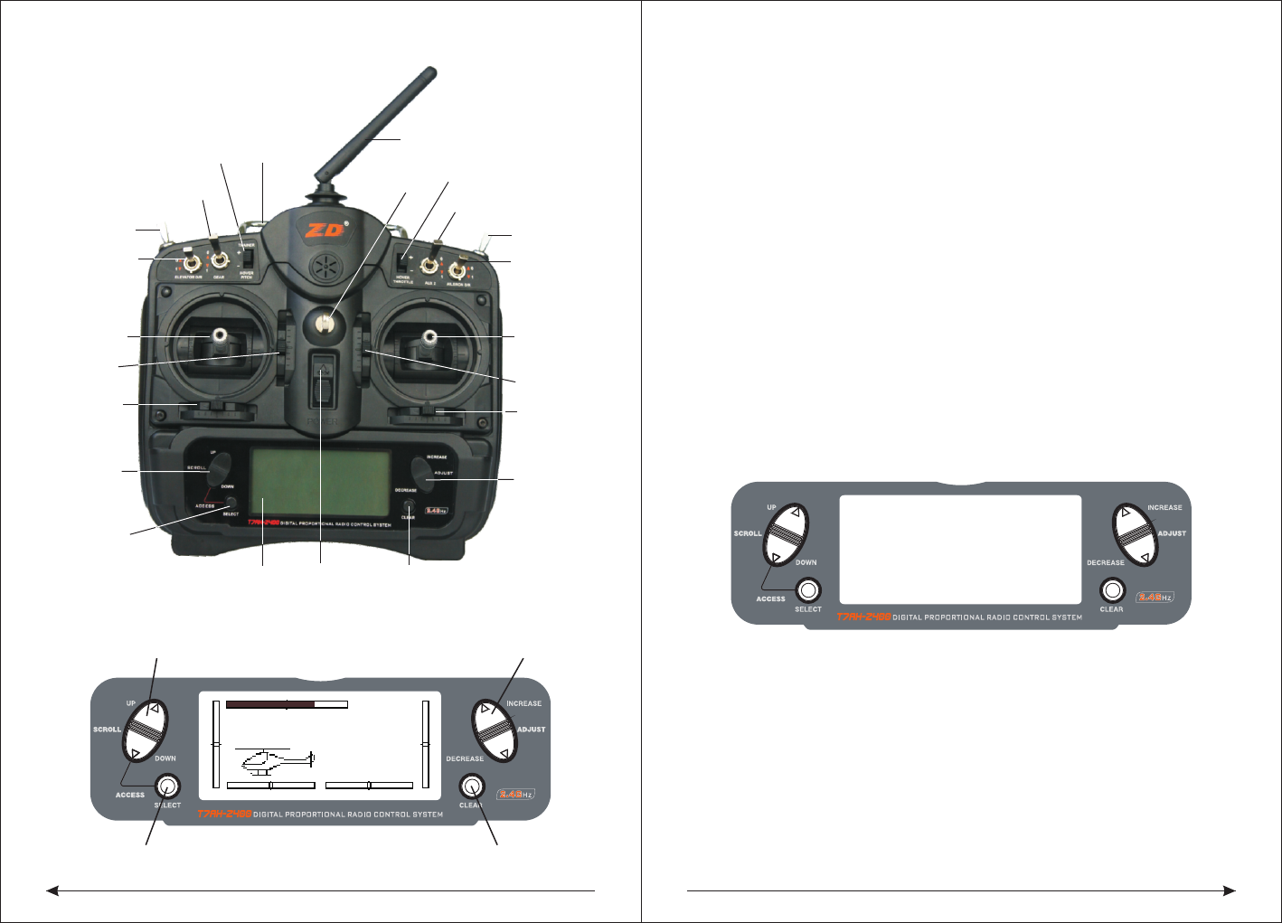
Control Identification and Location - Airplane Mode 1-ACRO
Throttle ALT
The Throttle ALT function makes the throttle stick trim active only when the throttle
stick is at less than half throttle. This allows accurate adjustments without affecting
the mid to high throttle position.
◆General Information
Press to adjust values
[THRO CURVE]
NORM
Point-L
51 51
0.0%
1 2 3 HL
IN OUT
Press to enter
THROTTLE CURVE
Press to enter
Function Mode
Press to select
desired points
12
MODEL 1
12.5ms FRAME RATE
10.6V
INCREASE and DECREASE keyUP and DOWN key
SELECT key CLEAR key
Landing
gear switch
Flaps switch
Lift wing ratio
Lift direction
rocker
Lift direction
fine-tuning
Direction wing
fine-tuning
scroll up and
down key
Switch key
The LED display Reset button
Data item
increase or
decrease
buttons
Aileron fine
-tuning
Throttle
aileron rocker
Throttle fine
-tuning
Aileron ratio
AUX2Switch
Direction
wing ratio
Hook
The power
switch
traner flaps
with the rocker Handle
Antenna
AUX2Rocker
13 14
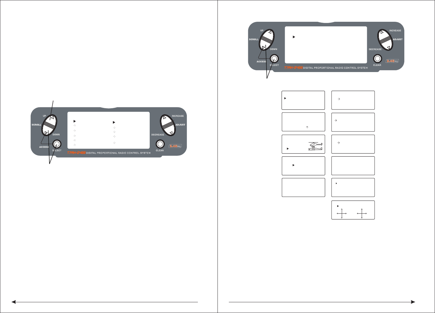
◇ Key Input and Display Functions
The UP and DOWN keys are used to select the programming function.
The SELECT key is used to select the channel or feature that you wish to program.
The INCREASE and DECREASE keys are used to change the values of the selected
programming feature.
T7AH-2400 features two programming modes: System Mode and Function Mode.
9.1System Mode Functions
System Mode
◇ To Enter the System List Mode
Press and hold the DOWN and SELECT keys simultaneously before turning
the power, then turn the transmitter power switch on to enter the System Mode.
While in the System Mode, press the UP and SELECT keys simultaneously to
access the “List” mode.
Use the UP and DOWN keys to scroll through the available function.
Press DOWN and SELECT to enter a selected function.
In this mode, servos are activated.
By pressing the DOWN and SELECT keys twice simultaneously, you can return to
the main screen.
◇To Enter the System Setup Mode
● With the power switch off, press and hold the DOWN and SELECT keys
simultaneously.
● Turn on the power switch.
● The system will display the last screen that was used in system set up mode.
You are now in System Mode.
◇ To Exit the System Setup Mode
● Press the DowN and SELECT keys simultaneously. The main screen will be
displayed.
[MODEL SELECT ]
SELECT
MODEL 1
ACRO DSM
Hold while turning on transmitter to enter System Mode
[MODEL NAME]
MODEL 1 ACRO
< >
[MODEL SELECT]
SELECT
MODEL 1ACRO
[ TYPE SELECT ]
MODEL 1
HELI
ACRO
[THRO RECOVERY]
INH
[MODEL RESET]
MODEL 1 ACRO
DATA RESET
INTEG-T
03:23:13
[D/R SWITCH SEL]
INVALID
[WING TYPE]
FLAPERON OFF
DELTA OFF
V-TAIL OFF
[TRAINER]
INH
[INPUT SELECT]
AUX2:2P SW
AUX2 TRIM:INH
FLAP:SYSTEM
FLAP TRIM:INH
GEAR:2P SW
Model Select (Page 15)
Model Name (Page 16)
Type Select (Page 16)
Model Reset (Page 17)
Trainer (Page 18)
Dual Rate Select
(Page 25)
Wing Type (Page 20)
Input Select (Page 19)
Throttle Recovery
(Page 46)
[SYSTEM LIST]
TRAINER
INPUT SEL.
WING TYPE
MODEL SEL
MODEL NAME
TYPE SEL.
MODEL RES.
UP and DOWN key
Hold while turning on transmitter
D/R SW
TH RECOV.
STICKMOD
CHNL RASS
[SKMODE SELECT]
ELEV
RUDD
THRO
AILE
MODE 1
[CHNO ASSGIN]
1:TH RO
2:AILE
3:EL EV
4:RU DD
5:GE AR
6:FLAP
7:AU X2
(Page 19)
Stick mode select
(Page 19)
Channel no assign
9.2 System Mode Flowchart
System Mode includes programming functions that are normally used during set up.
System programming functions include:
15 16
◇To Enter the Model Select Function
Press the DOWN and SELECT keys simultaneously and turn the power switch on
to access the System Setup Mode.
Press the INCREASE or DECREASE key until the MODEL SELECT appears on the
screen .
Press the INCREASE or DECREASE key to select the desired model memory.
◇ To Enter the Model Cope Function
Press the DOWN and SELECT keys simultaneously and turn the power switch on
to access the System Setup Mode.
Press the INCREASE or DECREASE key until the MODEL SELECT appears on the
screen .
Press the SELECT key to enter COPY SCREEN.
Press the INCREASE or DECREASE key to select the desired copy memory.
Press the CLEAR key to copy mode to the desired model memory.
Note: The model you copy to will have its memory replaced with the new model's
memory, and the programming information for the model to be copied will be erased.
◆Model Name
The Model Name function is used to input and assign the model's name to a specific
memory, allowing identification of each model's program. Each model's name is
displayed on the main screen when that model is selected. Up to eight letters and
numbers and are available.
◇To Enter the Model Name Function
Press the DOWN and SELECT keys simultaneously, then turn on the transmitter.
Press the UP or DOWN key until the MODEL NAME appears on the screen.
Press the SELECT key to move the cursor to the desired character's position.
Press the INCREASE or DECREASE key to select the desired character.
◇Type Select Function
The T7AH-2400 features two programming types: Airplane and Helicopter. The
DX7 can memorize data for up to six fixed wing aircraft and six helicopters model
and the model type will automatically be stored with each model memory.
Hold while turning on transmitter
[MODEL SELECT ]
SELECT
MODEL 1
ACRO
Hold while turning on transmitter
INCREASE and DECREASE keyUP and DOWN key
[MODEL SELECT]
MODEL 1HELI
MODEL 2ACRO
COPY
INCREASE and DECREASE key
Press to select
MODEL SELECT
Press to enter
function main screen
Press to enter
COPY screen
Press to copy
selected model
[MODEL NAME]
MODEL 1 ACRO
DSM <EXTRA 300>
Press to enter MODEL NAME
Hold while turning on transmitter
INCREASE and DECREASE key
[TYPE SELECT]
MODEL 1
HELI
INCREASE and DECREASE key
Press to enter
TYPE SELECT
ACRO
17 18
◇To Enter the Type Select Mode
Press the DOWN and SELECT keys simultaneously, then turn on the transmitter.
Press the UP key until the TYPE SELECT appears on the screen.
◇To Select a Model Type
Press the INCREASE or DECREASE key to witch between the heli or acro
model type.
press the CLEAR key to accept the new model type . All settings will be
set to the factory defaults if the selected memory group is previously used
type label
◆Model Reset and Integrated Timer Reset
The Model Reset function allows the model memory of the current model to be
reset to the factory default setting. This screen also allows the integrated timer to
be reset.
◇To Perform a DATA RESET or Reset the Integrated Timer
Press the DOWN and SELECT keys simultaneously, then turn on the transmitter.
.
◆Enhanced wireless Trainer
The T7AH-2400 offers a Wireless Trainer Function. Premise is the transmitter's and
transmitter's sets are the same
To Enter the Trainer Mode:
Press the DOWN and SELECT keys simultaneously, then turn on the transmitter.
Press the UP key until TRAINER function appears on screen.
Press the INCREASE or DECREASE key to activate or close Trainer function, then
TRAINER TRIM only used as a traniner switches.
◆Throttle Recovery
The T7AH-2400 has a unique throttle trim recovery feature. Throttle Recovery
stores the last known throttle trim position once throttle restore function is activated.
That stored position is then recalled by moving the throttle trim up (open) one notch
when the throttle trim is moved to the full down (closed) position. This makes shutting
off the engine and restarting it with the correct trim position easy.
To Activate the Throttle Recovery Function
Press the DOWN and SELECT keys simultaneously, then turn on the transmitter.
Press the UP key until THRO RECOVERY appears on screen.
Press the INCREASE or DECREASE key to turn on/off the Throttle Recovery function.
[TYPE SELECT]
MODEL 1
HELI
INCREASE and DECREASE key
Hold while turning on transmitter
ACRO
Accept new model type
YES CLEAR KEY
[MODEL RESET]
MODEL 1 ACRO
DATA RESET
INTEG-T
Press to enter MODEL RESET
Hold while turning
on transmitter
Press to select
RESET or INTEG-T
Press to reset
data or timer
0:00:34
INCREASE and DECREASE key
Press to select MODEL SELECT
Press to enter
function main screen
Press to enter
COPY screen
Press to copy
selected model
INH
[TRAINER ]
Press the UP or DOWN key until MODEL RESET appears on the screen.
Use the SELECT key to select DATA RESET or INTE-T.
When DATA RESET is selected, pressing the CLEAR key will reset the date to the
factory default setting for that model, or if INTE-T is selected, the integrated timer
will be reset to 0:00:00
◆Pole mode
The T7AH-2400 have in four different control rod "mode" (0, 1, 2, 3). Different mode
corresponding to operation function of different control rod. Usually, set in "mode" 1.
19 20
(The ROKER(HOVER THROTTLE) provides proportional trim function, while the
AUX2 channel allows the switch of 2 or 3 positions. Or you can inhibit the AUX2
rocker as well to prevent inadvertent changes. You can also choose the rocker as
an AUX2 channel proportional outputing. )
In addition, you have 3 choices to activate/inhibit FLAP SYSTEM:
● System (3-position switch)
● Rocker
● INH
(The ROKER(HOVER THROTTLE) provides proportional trim function, while the
AUX2 channel allows the switch of 2 or 3 positions. Or you can inhibit the AUX2
rocker as well to prevent inadvertent changes. You can also choose the rocker as
an AUX2 channel proportional outputing. )
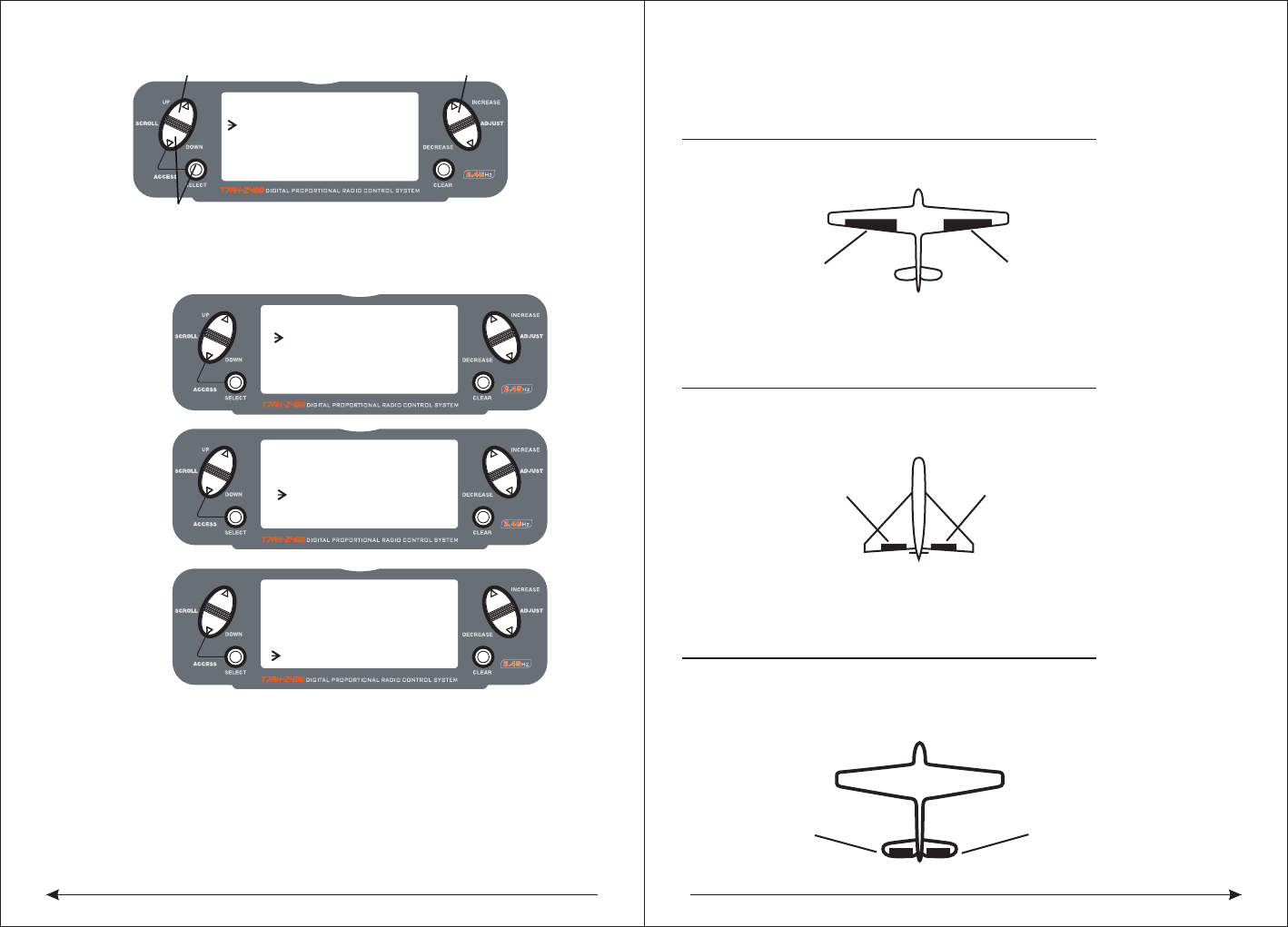
◆Wing Type
In the fixed wing mode, the 7AH-2400 offers three different wing types to choose
from: Normal, Flaperon and Delta. In addition, V-Tail mixing is available from the
Wing Type screen.
◆Normal
When the Flaperon and Delta wing function are off, Normal wing type is selected.
Use this wing type with common aircraft that utilize only one servo for both ailerons.
Normal is the default setting.
◆Flaperon Wing Type Selection
Flaperons require the use of one servo for each aileron and allow the use of
ailerons as flaps or spoilers. This function also allows the precise independent
adjust of up and down travel, and independent sub-trim and differential of each
aileron.
◇To Access Input Select
Press the DOWN and SELECT keys simultaneously, then turn on the transmitter.
Press the UP key until the INPUT SELECT function appears on screen.
Here you have 4 choices that can be used to operate auxiliary channel :
● 2-position switch
● 3-position switch
● Rocker
● INH
◆Delta Wing Type Selection
Delta wing arrangements combine the function of ailerons with the function of the
elevator to allow precise control of both roll and pitch.
[SKMODE SELECT]
MODE 1
ELEV
RUDD
THRO
AILE
◆Input Select
The purpose of the Input Selection Function is to assign the activation device for
the AUX2 channel and the FlAP Channel.
Change Pole mode
From Main Screen Display press the DOWN and SELECT keys simultaneously to
enter thFunction Mode.
Press the DOWN and SELECT keys simultaneously, the turn the transmitter on.
Press the UP key until SKMODE SELECT appear on green.
Press the INCREASE and DECREASE keys to change the pole mode.。
◆Channels Distribute
The T7AH-2400 can assign 7 channels to output in any channel, you can choose a
different style of the channel allocation, can also customize the output channel
allocation output.
[CHNO ASSGIN]
1:THRO
2:AILE
3:ELEV
4:RUDD
5:GEAR
6:FLAP
7:AUX2
[INPUT SELECT]
AUX2 TRIM:INH
FLAP: SYSTEM
Press to enter INPUT SELECT
Hold while turning on the transmitter
FLAP TRIM:INH
INCREASE and DECREASE key
AUX2: 2P SW
GEAR:2P SW
Change the channel distrubute
Press the SELECT and DOWN keys simultaneously and turn the transmitter on.
Press the UP key until CHNO ASSGIN appears on screen.
Press the SELECT key to select channel that you wish to output signal.
Press the INCREASE or DECREASE key to change the signal out putted by channel.
Press the CLEAR key restoring default values.
21 22
◇To Enter the Tail Wing Type Function
Press the DOWN and SELECT keys simultaneously, then turn on the transmitter.
Press the UP key until WING TYPE function appears on screen.
◇To Select a Wing Type
Press the INCREASE or DECREASE key until the desired wing type is highlighted
on screen: NORMAL, FLAPERON, DELTA WING.
Note: When Flaperon or Delta Wing type is selected, the travel adjustment is used
to adjust the individual servo throw, while the combined aileron travel is adjusted
with the aileron dual rate. It's also possible to set aileron differential. Reverse
switches are applicable for each servo. Neutral adjustments of each servo need
thought the Sub Trim Function to complete.
V-Tail Type Servo Connections
ELEV Servo Port
(Left V-Tail)
RUDD Servo Port
(Right V-Tail)
Triangle type steering gear connection.
● AILE servo port (right aileron)
● AUX1 servo port (left aileron)
◆ V tail type steering gear connection
◆ RUDD servo right aileron)
● AILE servo port (left aileron)
Flaperon Wing Type Servo Connections
• AILE ser
• AUX1 servo port (left aileron)
vo port (right aileron)
AUX1 Servo Port
(Left Aileron)
AILE Servo Port
(Right Aileron)
Flaperon WING Type Connection
AILE Servo Port
(Left Aileron)
ELEV Servo Port
(Right Aileron)
Delta Wing Type Connection
V-Tail Type Connection
RUDD servo port(right V-tail)
ELEV servo port (leftV-tail)
•
•
Delta Wing Type Servo Connections
ELEV servo port (right aileron)
AILE servo port (left aileron)
•
•
Flaperon Active:
[WING TYPE]
FLAPERON ON
V-TAIL OFF
V-Tail Active:
[WING TYPE]
FLAPERON OFF
V-TAIL ON
Delta Active:
[WING TYPE]
DELTA ON
[WING TYPE]
FLAPERON
DELTA
V-TAIL
Hold while turning on the transmitter
INCREASE and DECREASE key
OFF
OFF
OFF
WING TYPE FUNCTION
Press to enter ◆Flaperon Wing Type Servo Connections
● AILE servo port (right aileron)
● AUX1 servo port (left aileron)
23 24
◆Function Mode
◇To Enter Function Mode
● From Main Screen Display press the DowN and SELECT keys simultaneously to
enter the Function Mode.
● Use the UP or DowN keys to select the desired function.
● Use the SELECT key to scroll to the desired channel.
● Use the INCREASE and DECREASE keys to change the values or positions of
the selected channel.
● Use the CLEAR key is used to return the selected value to the factory default
settings.
9.3Function Mode Flowchart
Information pertaining to each function is explained on the following pages.
Functions will appear on the screen in the same order they are shown on the flow
chart below:
[D/R & EXP]
POS-0
AILE
D/R 100%
EXP LIN
OUTPUT
Dual Rate & Exponential (Page 26)
Servo Monitor
THRO
AILE
ELEV
RUDD
GEAR
FLAP
AUX2
(Page 38)Reverse Switch
[ REVERSING SW ]
NORM
GEAR
ch 1 2 3 4 5 6 7
REV.
(Page 27)
[PROG.MIX1]
THRO≥ THRO ON
RATE: 0%
0%
SW:ON
OFFSET: 0
Programmable Mixing (1-6) (Page 34)
[DIFFERENTIAL]
FLAPERON
NORM 0%
Differential (Page 32)
[FLAP SYS.] NORM
FLAP ELEV
NORM UP100% 0
0
0
MID
LAND
AUTO INH
DN100%
0%
Flap System
(Page 30)
Sub Trim
(Page 28)
[SUB TRIM]
THRO AILE
0 0
0 0
ELEV RUDD
[TRAVEL ADJUST]
THRO
H 100%
L 100%
ELEV
D 100%
U 100%
AILE
L 100%
R 100%
RUDD
L 100%
R 100%
Travel Adjust
(Page 29)
[AILE->RUDD MIX]
RATE: 0%OFF
SW: MIX
Aileron-to-RudderMix (Page 30)
Elevator-to-Flap (Page 30)
[ELEV->FLAP MIX]
RATE: D 0%ON
U 0%
SW:FLAP0
◆Function List Modes
The list mode screens display all the functions on screen allowing the access of
any function without having to scroll through each screen.
Note that there are two list modes: a System Setup List Mode and a Function List
Mode
To enter the Function List Mode, with the system on and in any function mode
screen, press the UP and SELECT keys simultaneously.
In list mode, pressing the UP and DOWN keys will move the cursor to the desired
function. Then pressing the DOWN and SELECT keys simultaneously will access
the selected function.
MODEL 1
12.5ms FRAME RATE
10.6V
INCREASE and DECREASE keyUP and DOWN key
SELECT key CLEAR key
[FUNCTION LIST]
DUAL RATE
EL≥FL MIX
TRAV ADJ.
SUB TRIM
REV. SW
EXPONENT.
PROG.MIX3
PROG.MIX2
PROG.MIX1
FLAP SYS.
AI≥RU MIX
UP and DOWN key
Press to enter function List Mode
INCREASE and DECREASE key
[ TIMER ]
MODEL 1
DOWN-T
00:00
Timer
(Page 36)
SW:ADJUST
25 26
◇To Enter the Function List Mode
● Turn the transmitter on.
● From the main screen, press the UP and SELECT keys simultaneously.
● The system is in Function List Mode now and will display a list of all the available
functions .
● Use the UP and DOWN keys to Scroll through the available function.
● Press DOWN and SELECT to enter a selected function.
◇To Exit the Function List Mode
● Press the DOWN and SELECT keys simultaneously twice. The system will return
to the main screen.
◆Dual Rate and Switch Select
The D/R switch select function allows the dual and expo rates to be selected via
individual switches (aileron, elevator and rudder D/R switches) or to be
conveniently combined
on a single switch. When combined to a single switch the following switch options
are available:
● COM AILE: Aileron D/R switch
● COM ELEV: Elevator D/R switch
● COM RUDD: Rudder D/R switch
● FLAP 2: Flap switch in the lower position
● FLAP 0: Flap switch in the upper position
● INDIVID: D/R activated by it’s individual aileron, elevator and rudder switches.
◇To Activate Dual Rate and Switch Select
Press and hold the DOWN and SELECT keys simultaneously to enter system mode.
Press the UP or DowN key until D/R SWITCH SEL appears on the screen.
Press the INCREASE or DECREASE keys to select the desired switch(es) you wish
to operate the D/R and Expo function.
and selectedwith a switch. Dual rates and expos are available on the aileron,
elevator and rudder channels. Changing the dual rate value not only affects the
maximum control authourity but also affects the overall sensitivity of control.
A higher rate yields a higher overall sensitivity. The sensitivity around center can
be tailored using the Exponential function to precisely adjust.
Dual and Expo rates can be controlled by their respective dual rate switches or by
one common switch. The choices for this are found on the D/R SWITCH SEL screen
in the System Setup Mode for Airplanes.
Dual rate values are adjustable from 0–125%. The factory default settings for both
the 0 and 1 switch positions are 100%. Exponential values are adjustable from -
100% to +100%. Either switch position may be selected as the low or high rate by
placing the switch in the desired position and adjusting the value accordingly.
◇To Adjust the Dual and Expo Rates
Press the DOWN and SELECT keys simultaneously to access the Function Mode.
In Function Mode, use the UP or DOWN keys to select the D/R or EXP screen.
Press the INCREASE or DECREASE key to select the desired channel.
Press the SELECT key to highlight the D/R or EXPO function.
Adjust the dual rate values for the selected switch position using the INCREASE or
DECREASE key.
[D/R & EXP]
POS-0
AILE
D/R 100%
EXP LIN
OUTPUT
Press to adjust value
Press to enter
DUAL RATE
Press to enter
Function Mode
Press to select
desired channel
Press to return value
to default setting
[ D/R SWITCH SEL ]
UP and DOWN key
Press to enter function List Mode
INCREASE and DECREASE key
INDIVID
◆Dual Rate and Exponential
The Dual Rate and Exponential function allows two control rates to be programmed
he Dual Rate and Expo functions for aileron, elevator and rudder can be combined
on a single switch, high or low rates to be selected via one switch. The choices for
this are found on the D/R SWITCH SEL screen in the System Setup Mode for
Airplanes.(have a look at page 50.)
The Exponential function allows two exponential rates to be programmed and
selected with a switch. Exponential is available on the aileron, elevator and rudder
channels. Changing the exponential value does not affect the maximum control
authority but only affects control sensitivity. Exponential is normally used to reduce
control sensitivity around neutral while still allowing high control authority at the
27 28
◇To Adjust the Exponential
Press the DOWN and SELECT keys simultaneously to access the Function Mode.
In Function Mode, use the UP or DOWN keys to select the DUAL RATE and
EXPONENTIAL screen.Press the INCREASE or DECREASE key to select the
desired channel (AILE, ELEV or RUDD).Move the selected channel’s dual rate
switch to the desired position, 0 or 1.Press the SELECT key until EXP is highlighted
on the screen.Using the INCREASE or DECREASE key to adjust the Expo rate values.
◆Reverse Switch
The Reverse Switch function allows electronic means of reversing the servo’s throw
. Servo reversing is available for all seven channels.
◇To Access the Reverse Switch Mode
Press the DOWN and SELECT keys simultaneously to access the Function Mode.
In Function Mode, use the UP or DOWN key to select the REVERSING SW screen.
Press the SELECT key to access the desired channel.
Press the INCREASE or DECREASE keys to reverse the servo direction
The available channels are:
● THRO: Throttle ● AILE: Aileron ● ELEV: Elevator ● RUDD: Rudder
● GEAR: Retractable Landing Gear ● FLAP: Flap ● AUX2: Auxiliary 2
◇To Access the Sub-Trim Function
Press the DOWN and SELECT keys simultaneously to access the Function Mode.
In Function Mode, use the UP or DowN key to select the SUB TRIM screen.
Press the SELECT key to access the desired channel.
Press the INCREASE or DECREASE keys to adjust the sub-trim position for that
selected channel.
[D/R & EXP]
POS-0
AILE
D/R 100%
EXP LIN
OUTPUT
Press to adjust value
Press to enter
DUAL RATE and EXPONENTIAL
Press to enter
Function Mode
Press to select
desired channel
Press to return value
to default setting
[REVERSING SW]
NORM
GEAR
ch 1 2 3 4 5 6 7
REV.
Press to select REV. or NORMPress to enter REVERSE
Press to enter
Function Mode
Press to select
desired channel
[SUB TRIM]
THRO AILE
0
ELEV
Press to enter SUB TRIM
Press to enter
Function Mode
Press to select
desired channel
Press to adjust sub-trim position
0
0
RUDD
0
extremes of throw. The sensitivity around center can be tailored using the
Exponential function to precisely adjust control feel.
Exponential rates can be controlled by their respective rate switches (aileron,
elevator and rudder), or combined on a single switch.The choices for this are found
on the D/R SWITCH SEL screen in the System Setup Mode for Airplanes.
Exponential is available for the aileron, elevator and rudder channels. Expo values
are adjustable from-100% (full negative expo), straight line, and +100% (full positive
expo). The factory default settings for both the 0 and 1 switch positions are straight
line or 0%. You can select one between the witch's two position to open the desirable
EXPO rate. The position of the switch is the place of ajusting the accordingly EXPO
Note: A negative Expo value will increase sensitivity around neutral, and a
positive Expo value will decrease sensitivity around neutral. Normally a
positive value is used to insensitize control response around neutra
value.
◆Sub-Trim
The Sub-Trim function allows you to electronically adjust the centering of each
servo. Sub trim is individually adjustable for all seven channels, with a range of +
or - 125% (+ or - 30 degrees servo travel).
Caution: Do not use excessive sub-trim values as it is possible to overdrive the
servo’s maximum travel.The available channels are:
● THRO: Throttle ● AILE: Aileron ● ELEV: Elevator ● RUDD: Rudder
● GEAR: Retractable Landing Gear ● FLAP: Flap ● AUX2: Auxiliary 2
29 30
◆Travel Adjust
The Travel Adjust function allows the precise end-point adjustments of all seven
channels in each direction independently. The travel adjust range is from 0–150%.
Channel available for programming are:
● THRO: Throttle ● AILE: Aileron ● ELEV: Elevator ● RUDD: Rudder
● GEAR: Retractable Landing Gear ● FLAP: Flap ● AUX2: Auxiliary 2
◇To Access the Travel Adjust Function
Press the DOWN and SELECT keys simultaneously to access the Function Mode.
In Function Mode, use the UP or DOWN key to select the TRAVEL ADJUST screen.
Press the SELECT key to access the desired channel.
Move the selected channel’s stick or switch in the desired direction that you wish to
adjust.
Press the INCREASE or DECREASE keys to adjust the end-point position for that
selected channel's direction.
◇To Access the Elevator-to-Flap Mixing
In the Function Mode, use the UP or DOWN key to select the ELEVATOR TO FLAP
MIXING function and press the UP and DowN keys simultaneously to access.
Note: The flap mix switch, or the Mix switch, no matter which is selected, must be
in the“ON” position to adjust values.
To adjust the rate value, with the switch on, move the elevator stick in the desired
position and press the INCREASE or DECREASE key to adjust the desired mix value.
◇To Select the Switch to Operate the Flap Mix
Press the SELECT key to highlight SW.
Press the INCREASE or DECREASE key to select the MIX or FLAP0 switch.
[TRAVEL ADJUST]
THRO
H 100%
L 100%
ELEV
D 100%
U 100%
AILE
L 100%
R 100%
RUDD
L 100%
Selected channel
Press to enter
TRAVEL ADJUST
Press to enter
Function Mode
Press to return
value to default
Press to select
desired channel
R 100%
Press to adjust value
Press to enter TRAVEL ADJUST
[ ELEV - FLAP MIX ]
Press to enterFunction Mode Press to select desired channel
Press to adjust value
RATE: D 0%
SW: FLAPO
U 0%
ON
[ AILE- RUDD MIX ]
Press to enter TRAVEL ADJUST
Press to enter Function Mode Press to select desired channel
Press to adjust value
RATE: 0%
SW: MIX
OFF
◆Elevator-to-Flap Mix Function
When the Elevator-to-Flap Mixing System is active, and a value of flaps is inputted,
the flaps will be deflected each time the elevator stick is used. The actual flap
movement is independently adjustable for both up and down elevator. When used
in this manner, the aircraft pitches much more quickly than normal. The uppermost
position of the Flap Mixing Switch or the Mix Switch can be used to activate the
Elevator-to-Flap Mixing function. When you want to reverse the mixing directions,
press the - key to change the mixing value from + to - (or - to +).
◆Aileron-to-Rudder Mixing
If the Aileron-to-Rudder Mixing function is designed, the rudder servo will move
when the aileron stick is used, eliminating the need to coordinate these controls
manually. This mixing program can be turned ON/OFF by a switch. The switches
that can be selected are shown below, with their abbreviations as they appear on
the screen and the corresponding switch positions. Mix values are adjustable
from 0 to 125%. When adjusting the mix value, if an opposite mixing direction of the
rudder servo is required, simply press the INCREASE or DECREASE key to change
the mixing value from + to - or - to +. This will reverse the mixing direction of the
rudder from its original direction.
● ON: Mixing Always ON ● MIX Switch ON/OFF Using Mixing Switch
● Flap 0 Switch ON/OFF Using Flap Mix Position 0
● Flap 2 Switch ON/OFF Using Flap Mix Position 2
31 32
◇To Access the Aileron-to-Rudder Mix Function
Press the DOWN and SELECT keys simultaneously to access the Function Mode.
In Function Mode, use the UP or DOWN key to select the AILE-RUDD MIX screen.
Press the SELECT key to select RATE or SW (switch).
◇To Adjust the Mix Value
With RATE highlighted, press the INCREASE or DECREASE keys to adjust the
mix value. Note: reversing mix directions is accessible.
◇To Assign a Switch
With SW be choosed, press the INCREASE or DECREASE keys to select the
desired switch used to turn on/off the mix (Flap 0 or Mix).
◆Flap System
The purpose of the Flap System is to set the flap and elevator positions for landing
and takeoff. This is accomplished by selecting values for the elevator and flaps to
be activated when the Land Switch is engaged. Three flap and elevator positions
are available. The landing system can also be activated by a preset position of the
throttle stick. Refer to the Automatic Landing Attitude section for more information
on how to select the preset throttle position.
Note: The Flap System is only be accessed when SYSTEM is selected under Flap
in the Input Select screen. See page 46 for more detail
◇Accessing and Utilizing the Flap System
Press the UP and SELECT keys simultaneously to enter the Function Mode.
Press the UP or DOWN keys until FLAP SYS appears in the upper left portion of the
LCD. Press the SELECT key to move the cursor at the desired function (i.e., ELEV,
FLAP , SPOI, AUTO). Note: The flap system can only be accessed when SYSTEM
is selected in the Input Select screen under flaps. See page 41 for more details.
Press the UP or DOWN keys to set the flap and elevator travel. The UP key adds up
flap/elevator and the DOWN key adds down flap/elevator. The input is adjustable
from 125% for flap and -200% for elevator.
◆Automatic Landing
When the Automatic Landing Function is active, the throttle stick will activate the
landing system you have just set up. Any point of throttle stick travel can be set as
the “auto-land” point. Once the throttle stick passes through this point and the
LAND switch is in the MID, or land position, the landing system will be activated.
Thus, the elevator and flaps would be activated. If the flap mixing switch is not in
the LAND position, the throttle stick operation would have no effect on the landing
system.
◇To Activate the Automatic Landing Feature
In the FLAP SYS. screen, press the SELECT key until AUTO is selected.
Press the INCREASE or DECREASE key to activate the AUTOMATIC LANDING
SYSTEM. Press the INCREASE or DECREASE key to adjust the value (0% = low
stick while 100% = full stick). To clear the auto land point, press CLEAR key and
the display will return to INH.
◆Differential Aileron Mixing
Note: Only available when Flaperon or Elevon is selected, the Differential System
is available (see Tail Wing Type Page 44).
The Differential Aileron function allows precise electronic adjustments of the up vs
. down aileron travel of both ailerons. Aileron differential is used to reduce unwanted
yaw characteristics during roll inputs. In order to access the Differential Function,
flaperon or elevon wing mixing must be selected and two servos must be used to
operate the ailerons.
[FLAP SYS.] NORM
FLAP ELEV
NORM UP100% 0
0
0
MID
LAND
AUTO INH
DN100%
0%
Press to enter FLAP SYSTEM
Press to enter
Function Mode
Press to return
value to default
Press to highlight
the desired function
Press to adjust value
[ DIFFERENTIAL ]
Press to enter DIFFERENIAL
Press to enterFunction Mode Press to return value to default
Press to adjust value
FLAPERON
NORM 0%
[FLAP SYS.] NORM
FLAP ELEV
NORM Up100%
0
0
MID
LAND
AUTO INH
DN100%
0%
Press to enter FLAP SYSTEM
Press to enterFunction Mode Press to return value to default
Press to adjust value
0
33 34
◇To Access the Differential Aileron Mixing Function
Press the DOWN and SELECT keys simultaneously to access the Function Mode.
In Function Mode, use the UP or DOWN key to select the Differential screen.
Press the INCREASE or DECREASE keys to adjust the Differential value.
Note: Increasing the value will reduce the amount of down travel in each aileron.
If differential is working in reverse, it means the aileron servos are plugged into the
wrong channels. The right aileron should be plugged into the aileron channel,
while the left aileron should be plugged into the flap channel.
◆throttle idle
Throttle idle function used to safety close engine, for fixed wing
aircraft, it is always a very safe switch, lock throttle to the closed position. When
the throttle lock switch is activated, and all the other servos are normal, throttle
idle function lock throttle servo/ESC to specific position (normal low or close the
throttle). Throttle idle switch is also can be selected. Switch choice positions
including rudder double proportion, auxiliary 2, aileron double row or the elevator
servo's double ratio switch position
◇To Access the Throttle Idle Function
Press the DOWN and SELECT keys simultaneously to access the Function Mode.
In Function Mode, use the UP or DOWN key to select the THRO HOLD screen.
Press the INCREASE or DECREASE key to activate the throttle idel function.
When activated, press the INCREASE or DECREASE key to change the throttle
idel value.
◇To Access the Throttle Idle Switch Function
Press the SELECT key to highlight switch.
Press the INCREASE or DECREASE key to select the desired switch.
◆Programmable Mixing 1–6
The T7AH-2400 offers six programmable mixes that allow stick or switch inputs to
control the output of two or more servos. This function allows any channel mixing
to any other channel, or to mix a channel to itself. The mix can remain ON at all
times, or it can be switched OFF when using a number of different switches in flight.
Mix values are adjustable from 0 to 125%. Each channel is identified by a four-
character name (i.e., Aileron - AILE, Elevator - ELEV, etc.). The channel appearing
first is the master channel. The second channel is the auxiliary channel. For
example,AILE - RUDD indicates aileron-to-rudder mixing. Each time the aileron
stick is moved, the rudder will automatically move in the direction and to the position
based on the value input in the programmable mix screen. Mixing is proportional,
because small inputs of the master channel will produce small outputs of the slave
channel. Each programmable mix has a mixing offset. The purpose of the mixing
offset is to redefine the neutral position of the slave channel.
◇Assigning Channels
Press the DOWN and SELECT keys simultaneously to access the Function Mode.
In Function Mode, use the UP or DowN keys to select the desired PROG. MIX
screen (1–6).
Press the INCREASE or DECREASE keys to select the desired master channel.
Press the SELECT key to highlight the slave channel.
Press the INCREASE or DECREASE keys to select the desired auxiliary channel.
[PROG.MIX1]
THRO THRO ON
RATE: 0%
0%
SW:ON
OFFSET: 0
or SLAVE CHANNEL
Press to enter PROG MIX
Press to enter
Function Mode
Press to return
value to default
Press to highlight
MASTER CHANNEL
or SLAVE CHANNEL
Press to select MASTER CHANNEL
[PROG.MIX1]
THRO THRO ON
RATE: 0%
0%
SW:ON
OFFSET: 0
Press to enter PROG MIX
Press to enter
Function Mode
Press to return
value to default
Press to highlight
RATE
Press to adjust MIX value
[THRO IDL]
SW:RUDD D/R
HOLD POS. -5.0%
Press to enter THROTTLE HOLD
Press to enter
Function Mode
Press to return
value to INH
Press to select
desired channel
Press to activate THROTTLE HOLD and change values
ON
35 36
◇Assigning Mixing Values
Press the DOWN and SELECT keys simultaneously to access the Function Mode.
In Function Mode, use the UP or DOWN keys to select the desired PROG. MIX screen
Press the SELECT key to select RATE.
Using the stick or switch that is assigned to the master channel, move that stick or
switch in the desired direction that you wish to adjust the mix value.
Press the INCREASE or DECREASE key to adjust the mix value. The values are
adjustable from -125% to +125%.
◇Assigning an Offset
Press the DOWN and SELECT keys simultaneously to access the Function Mode.
In Function Mode, use the UP or DOWN keys to select the desired PROG. MIX screen
Press the SELECT key to select OFFSET.
To establish the offset position, use the INCREASE or DECREASE keys to change
the value to the desired point. The stored offset value will appear on screen.
To change the offset value, simply use the INCREASE or DECREASE key to change
the value. Pressing the CLEAR key will reset the offset to 0.
◇Assigning a Switch
Press the DOWN and SELECT keys simultaneously to access the Function Mode.
In Function Mode, use the UP or DOWN keys to select the desired PROG. MIX screen.
Press the SELECT key to select SW.
Use the INCREASE or DECREASE key to select the desired switch to turn on/off
the mix.
● ON: Mixing Always On ● MIX: Mixing Switch Toward Self
● Flap 0: Flap Switch in Flap 0 Position ● Flap 2: Flap Switch in Flap 2 Position
● Gear: Gear Switch
◆Timer
TheT7AH-2400 features an onscreen timer with three programming options.
INH:
Inhibit- In this mode the timer is turned off.
Down-T:
Down Timer- The countdown timer allows a preset time in ten-second intervals up
to 59 minutes and 50 seconds to be programmed, and when that time before the
expiry of 10 S, a beeper will sound for 10 seconds.
STOP-W:
Stopwatch- The stopwatch function is a simple count-up timer that displays
minutes and seconds up to 59 minutes and 59 seconds. And when that time before
the expiry of 10 S
, a beeper will sound for 10 seconds.
When the DOWN-T or STOP-W function is selected, the timer will be displayed on
the main screen. The following buttons are used in conjunction to operate the time
r function:
[PROG.MIX1]
THRO THRO ON
RATE: 0%
0%
SW:ON
OFFSET: 0
Press to enter PROG MIX
Press to enter
Function Mode
Press to return
value to default
Press to highlight
OFFSET
Press to adjust OFFSET value
When choosing the throttle idle speed as switch to activate of the timer, it
will display the percentage of throttle idling for choosing.It is independent of
the set.
CLEAR key:
Used to reset the timer to the preset time or to reset the stopwatch timer to 0:00.
SW:ADJUST ADJUST
THRO IDL Switch of throttle trip percentage
Press to select TIMER
Press to enter
Function Mode
Press the CLEAR key
to reset the DOWN-T
to 10:00 minutes
Press the SELECT key
to access INH, DOWN-T
or STOP-W
Press the INCREASE or DECREASE
key to set the down timer
[ TIMER ]
MODEL 1
DOWN-T
00:00
SW:ADJUST
37 38
◇To Access the Timing Function
Press the DOWN and SELECT keys simultaneously to access the system mode.
In System Mode, use the UP or DOWN key to select the TIMER screen.
Press the SELECT key to select STOP-W, DOWN-T or INH.
With DOWN-T selected press the INCREASE or DECREASE key to change the
preprogrammed time.
◇To Access the Timing Control and Switch Function
Press the DOWN and SELECT keys simultaneously to access the system mode.
In System Mode, use the UP or DOWN key to select the TIMER screen.
Press the SELECT key to select STOP-W, DOWN-T or INH key or switch.
With STOP-W selected, press the INCREASE or DECREASE key to select the key
and switch.
Press the DOWN and SELECT keys simultaneously to access the system mode.
In System Mode, use the UP or DOWN key to select the TIMER screen.
Press the SELECT key to select STOP-W, DOWN-T or INH.
With DOWN-T selected press the INCREASE or DECREASE key to change the
preprogrammed time.
After choosing the countdown timer and press INCREASE or DECREASE key to
change the good programming time in advance.
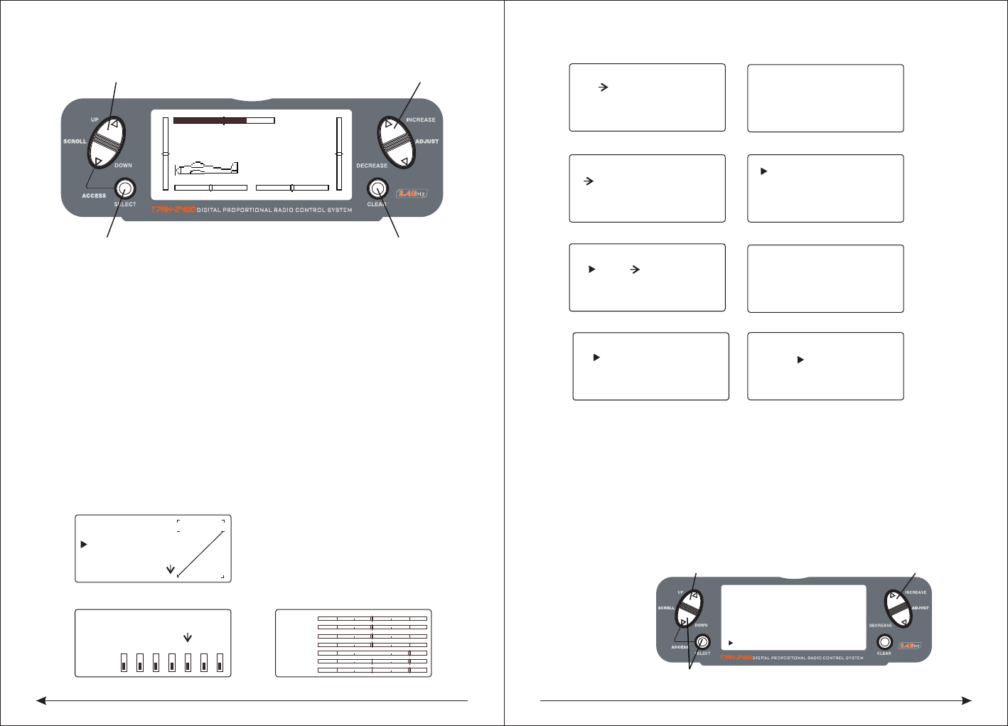
◆Servo Monitor
The servo monitor screen serves as a useful tool when programming your radio. It
displays servo positions and is useful in checking different programming functions.
TEN, Helicopter Programming guide
Transmitter Control Identification and Location
MODEL 110.6V
12.5ms FRAME RATE
DOWN-T
10:00
Press the INCREASE or DECREASE
Press the CLEAR key to reset the timer
key to start or stop the timer
MODEL 110.6V
12.5ms FRAME RATE
DOWN-T
10:00
Press the INCREASE or DECREASE
Press the CLEAR key to reset the timer
key to start or stop the timer
THRO
AILE
ELEV
RUDD
GEAR
FLAP
AUX2
Press to enter SERVO MONITOR
Press to enter Function Mode
Press to select TIMER
Press to enter
Function Mode
Press the CLEAR key
to reset the DOWN-T
Press the SELECT key
to access INH, DOWN-T
or STOP-W
Press the INCREASE or DECREASE
key to set the down timer
[ TIMER ]
MODEL 1
DOWN-T
00:00
SW:ADJUST
39 40
◆Boot screen
◇Input and Display Functions
● The UP and DowN keys are used to select the programming function.
● The SELECT key is used to select the channel or feature that you wish to program.
● The INCREASE or DECREASE keys are used to change the values of the
selected programming feature.
The DX7 features two programming modes: System Setup Mode and Function
Mode, which are described in the next sections.
◆Throttle Hold/Stunt Mode
When the T7AH-2400 is operated in the helicopter mode, there is a warning system
that is employed to avoid hot starts (accidental high throttle startups). If the power
switch is turned on, and throttle switch is on high throttle, an alarm will sound and
a warning message will be displayed on the LCD. When all switches are returned
to the normal condition, the display will return to normal.
Note: If the Throttle Hold function is not activated before the power switch being
turned on, no alarm will sound. Below is the display example of warning condition
when the power switch is on.
◆Gyro Connections
Note: The Gyro Gain channel can be selected to operate on Channel 5 (Gear) or
Channel 7 (AUX2). See input Select on Page 78 for detail on selecting the gain
channel.
10.1 System Setup Mode
Includes programming functions that are normally used during setup.
System Setup programming functions include:
WARNNING
F.MODE
MODEL 1
12.5ms FRAME RATE
10.6V
INCREASE and DECREASE keyUP and DOWN key
SELECT key CLEAR key
Landing
gear switch
Flaps switch
Lift wing ratio
Lift direction
rocker
Lift direction
fine-tuning
Direction wing
fine-tuning
scroll up and
down key
Switch key
The LED display Reset button
Data item
increase or
decrease
buttons
Aileron fine
-tuning
Throttle
aileron rocker
Throttle fine
-tuning
Aileron ratio
AUX2Switch
Direction
wing ratio
Hook
The power
switch
traner flaps
with the rocker Handle
Antenna
AUX2Rocker
41 42
[SWASH TYPE]
1 SERVO
NORM
Swash Type (Page 49)
[THRO RECOVERY]
INH
Throttle Recovery
(Page 46)
Model Select (Page 43)
SELECT
MODEL 1
HELI
[MODE SELECT]
Model Name (Page 43)
[MODEL NAME]
MODEL 1 HELI
< >
Input Select (Page 47)
[INPUT SELECT]
AUX2 GEAR
GYRO GEAR
Type Select (Page 44)
[TYPE SELECT]
MODEL 1
HELI
ACRO
Model Reset (Page 45)
[MODEL RESET]
MODEL 1 HELI
DATA RESET
INTEG-T
03:00:34
◇To Enter the System Setup Mode
● With the power switch off, press the DOWN and SELECT keys simultaneously.
● Turn on the power switch.
● The system will display the last system setup screen that was used.
◇To Exit the System Setup Mode
● Press the DOWN and SELECT keys simultaneously.
● The main menu will be displayed
● Or turn the transmitter off to exit the System Setup Mode
◆Model Select/Copy
The T7AH-2400 features a memory function that stores the programmed data for
up to 6 models. Any combination of up to 6 airplanes and/or helicopters can be
stored in memory. A model name feature with up to eight characters allows each
model to be easily identified.
◇To Enter the Model Select Function
Press the DOWN and SELECT keys simultaneously, then turn the power switch on
to access the System Setup Mode. Press the INCREASE or DECREASE key until
the MODEL SELECT appears on screen.
Press the INCREASE or DECREASE key to select the desired model memory.
MODEL 1
12.5ms FRAME RATE
10.6V
INCREASE and DECREASE keyUP and DOWN key
HOLD while turning on transmitter CLEAR key
[MODEL SELECT ]
SELECT
MODEL 1 T-REX
ACRO
Hold while turning on transmitter
UP and DOWN key INCREASE and DECREASE key
[MODEL SELECT]
MODEL 1HELI
MODEL 2ACRO
COPY
INCREASE and DECREASE key
Press to select MODEL SELECT
Press to enter
function main screen
Press to enter
COPY screen
Press to copy
selected model
[SKMODE SELECT]
ELEV
RUDD
THRO
AILE
MODE 1
Stick mode select(Page 19)
[CHNO ASSGIN]
1:THRO
2:AILE
3:ELEV
4:RUDD
5:GEAR
6:PIT.
7:AUX2
Channel no assign(Page 19)
[TRAINER]
INH
Throttle Recovery (Page 46)
43 44
◇To Enter the Copy Function
● Press the DOWN and SELECT keys simultaneously and turn the power switch
on to access the System Setup Mode.
● Press the UP or DOWN key until MODEL SELECT appears on screen.
● Press the SELECT button to enter the COPY screen.
● Press the INCREASE or DECREASE keys to select to model that you wish to
copy the model.
● Press the CLEAR key to copy the model to the selected model memory.
Note: Be aware that the model that you copy will have its memory replaced with the
new model and the programming information for that model will be erased.
◆Model Name
The Model Name function is used to input and assign the model's name to a specific
memory, allowing easy identification of each model's program. Each model's name
is displayed on the main screen when that model is selected. Up to eight characters
and numbers are available.
◇To Enter the Model Name Function
Press the DOWN and SELECT keys simultaneously, then turn on the transmitter.
Press the INCREASE or DECREASE key until the MODEL NAME screen appears.
Press the SELECT Key to move the cursor to the desired character's position.
Press the INCREASE or DECREASE key to select the desired character.
◆Type Select Function
The T7AH-2400 features two programming types: Airplane and Helicopter. The
T7AH-2400 can memorize data for up to 6 models individually.
◇To Enter the Type Select Mode
Press the DOWN and SELECT keys simultaneously, then turn on the transmitter.
Press the UP key until the TYPE SELECT function appears on screen.
◇To Select a Model Type
Press the INCREASE or DECREASE key to change between the heli or acro model
types.To accept the new model type by pressing the CLEAR key.
◆Model Reset/Integrated Timer
The Model Reset function resets all programming functions to their default settings.
This screen also allows you to reset the integrated timer function to zero.
[TYPE SELECT]
MODEL 1
HELI
INCREASE and DECREASE key
Press to enter TYPE SELECT
Hold while turning on transmitter
ACRO
[MODEL NAME ]
MODEL 1 ACRO
(T-REX450)
Press to enter MODEL NAME INCREASE and DECREASE key
Press to enter main screen
[TYPE SELECT]
MODEL 1
HELI
INCREASE and DECREASE key
ACRO
YES CLEAR KEY
Press to accept new model type
45 46
◇To Reset a Model
● Press the DOWN and SELECT keys simultaneously, then turn on the transmitter.
● Press the UP key until MODEL RESET appears on screen.
● Press the SELECT key until DATA RESET is highlighted.
● Pressing the CLEAR key will reset the model memory to factory default settings.
◇To Reset the Integrated Timer
● Press the DOWN and SELECT keys simultaneously, then turn on the transmitter.
● Press the UP key until the MODEL RESET function appears on screen.
● Press the SELECT key until INTEg-T is highlighted.
● Pressing the CLEAR key will reset the INTEG-T to factory zero.
◆Enhanced wireless Trainer
The T7AH-2400 offers a Wireless Trainer Function. Premise is the transmitter's
and transmitter's sets are the same.
To Enter the Trainer Mode:
Press the DOWN and SELECT keys simultaneously, then turn on the transmitter.
Press the UP key until TRAINER function appears on screen.
Press the INCREASE or DECREASE key to activate or close Trainer function, then
TRAINER TRIM only used as a trainer switches.
◆Throttle Recovery
The T7AH-2400 has a unique throttle trim recovery feature. Throttle Recovery
stores the last known throttle trim position once throttle restore function is
activated. That stored position is then recalled by moving the throttle trim up
(open) one notch when the throttle trim is moved to the full down (closed) position.
This makes shutting off the engine and restarting it with the correct trim position easy.
To Activate the Throttle Recovery Function
Press the DOWN and SELECT keys simultaneously, then turn on the transmitter.
Press the UP key until THRO RECOVERY appears on screen.
Press the INCREASE or DECREASE key to turn on/off the Throttle Recovery function.
◇To Activate the Throttle Recovery Function
Press the DOWN and SELECT keys simultaneously, then turn on the transmitter.
Press the UP key until THRO RECOVERY appears on screen.
Press the INCREASE or DECREASE key to turn on/off the Throttle Recovery function.
[MODEL RESET]
MODEL 1 ACRO
DATA RESET
INTEG-T
Press to enter MODEL RESET
Hold while turning
on transmitter
Press to select
RESET or INTEG-T
Press to reset
data or timer
00:00:34
[MODEL RESET]
MODEL 1 ACRO
DATA RESET
INTEG-T
Press to enter MODEL RESET
Hold while turning
on transmitter
Press to select
RESET or INTEG-T
Press to reset
data or timer
00:00:34
INCREASE and DECREASE key
INCREASE and DECREASE key
Press to enter
function main screen
Press to enter
COPY screen
Press to copy
selected model
INH
TRAIN RECOVERY
[ ]
Press to enter THROTTLE RECOVERY
◆Pole mode
The T7AH-2400 have in four different control rod "mode" (0, 1, 2, 3). Different
mode corresponding to operation function of different control rod. Usually, set in
"mode" 1.
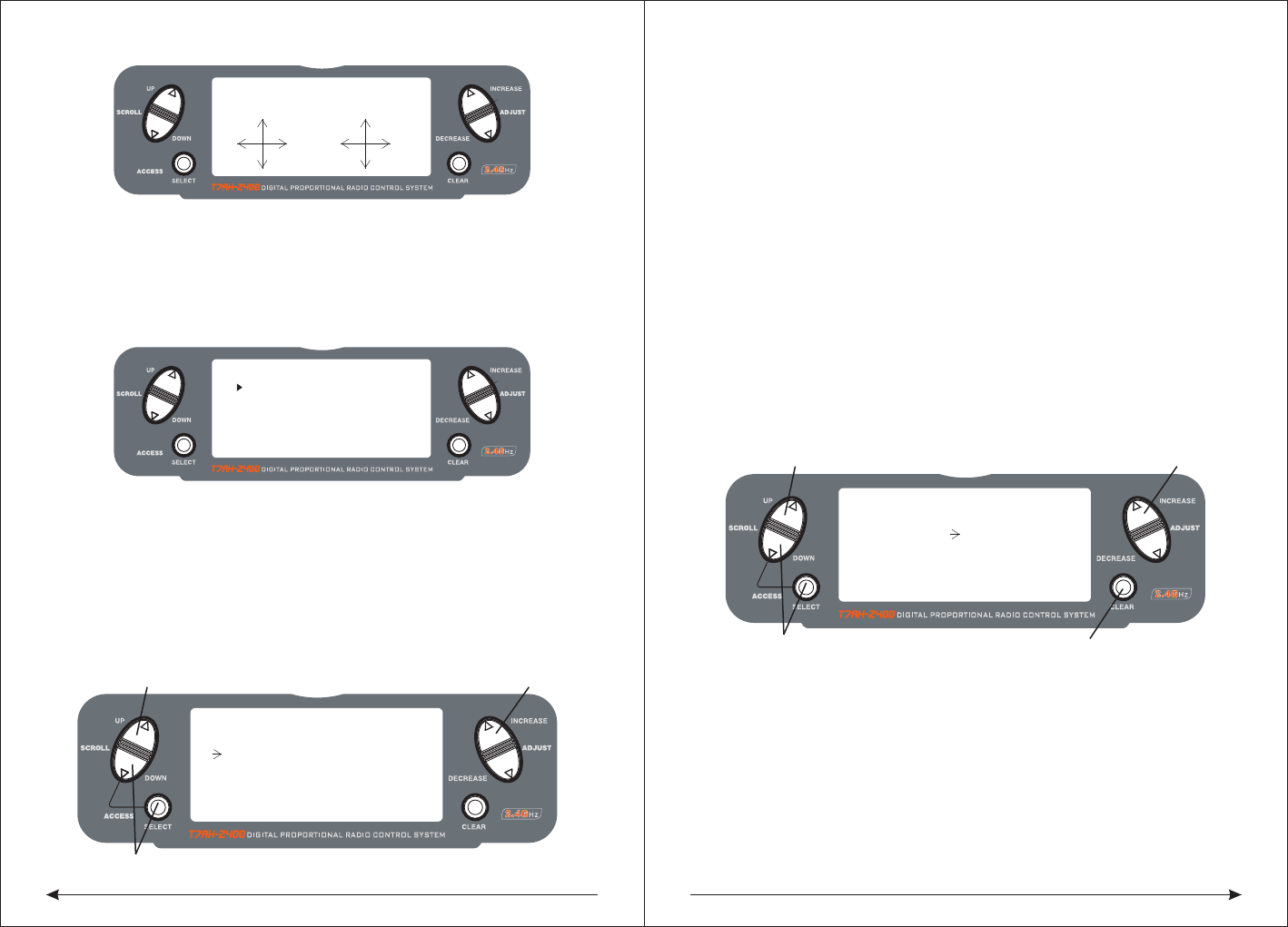
47 48
Change the channel distribute
Press the SELECT and DOWN keys simultaneously and turn the transmitter on.
Press the UP key until CHNO ASSGIN appears on screen.
Press the SELECT key to select channel that you wish to output signal.
Press the INCREASE or DECREASE key to change the signal out putted by channel.
Press the CLEAR key restoring default values.
◆Input Select
The Input Select function is used to select the switch input for the gyro gain and the
channel that will operate.
To Select the Function for the AUX2 Channel
Press the DOWN and SELECT keys simultaneously, then turn on the transmitter.
Press the UP or DOWN key until the INPUT SELECT function appears on screen.
Press the SELECT key until AUX2 is highlighted.
Press the INCREASE or DECREASE key to select the desired function.
◇To Select the Function for the Gear Channel
Press the DOWN and SELECT keys simultaneously, then turn on the transmitter.
Press the UP or DOWN key until INPUT SELECT appears on screen.
Press the SELECT key until GEAR is highlighted.
Press the INCREASE or DECREASE key to select the desired function.
The gear channel options are:
INH:
Inhibit is selected if the gyro function will not be used on the gear channel.
Selecting inhibit turns off the channel, allowing it to be used as a slave channel fo
mixing.
INCREASE and DECREASE key
Press to enter INPUT SELECT
Hold while turning on transmitter
[INPUT SELECT]
AUX2 GEAR
GYRO INH
INCREASE and DECREASE key
Press to enter INPUT SELECT
Hold while turning on transmitter
[INPUT SELECT]
AUX2 GEAR
INH INH
Press to reset
[SKMODE SELECT]
MODE 1
ELEV
RUDD
THRO
AILE
Change Pole mode
Press the DOWN and SELECT keys simultaneously, the turn the transmitter on.
Press the UP key until SKMODE SELECT appear on green.
Press the INCREASE and DECREASE keys to change the pole mode.
The T7AH-2400 can assign 7 channels to output in any channel, you can choose a
different style of the channel allocation, can also customize the output channel
allocation output.
[CHNO ASSGIN]
1:THRO
2:AILE
3:ELEV
4:RUDD
5:GEAR
6:FLAP
7;AUX2
The Auxiliary 2 channel options are:
INH:
Inhibit is selected if the gyro function will not be used on the Aux 2 channel.
F.MODE:
In this mode, the AUX2 channel is controlled by the flight mode switch and three
positions are available. Sub trim and travel adjust is used to set the center and
end points for each switch position.
AUX2:
The Auxiliary 2 switch controls the AUX2 Channel.
GYRO:
The gyro mode is selected if you want to use the Gyro Sensing (see page 96) for
more detail. Selecting GYRO under AUX2 assigns the gyro sensing program to
operate use the AUX2 channel. In this case the gyro gain must be plugged into the
AUX2 (Channel 7) channel.
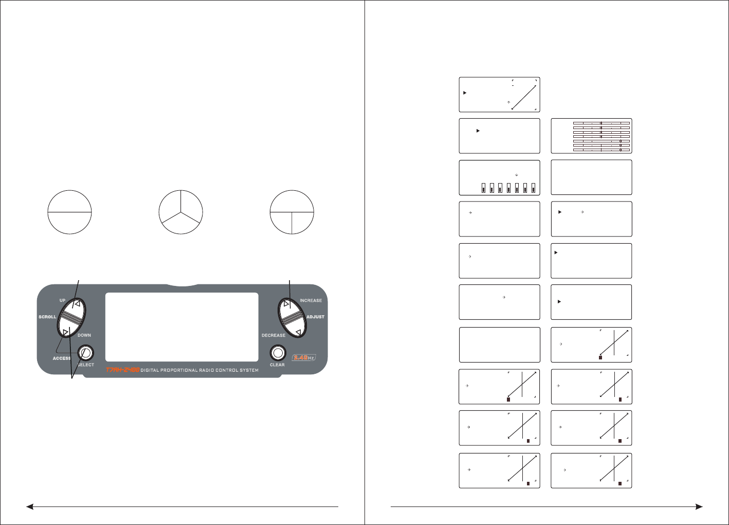
49 50
2 Servo/180 CCPM 3 Servo/120 CCPM
(most popular) 3 Servo/90 CCPM
Ch6Ch2
Ch3
Ch2 Ch6
Ch3
Ch2 Ch6
◇Accessing the Swashplate Types
While pressing the DOWN and SELECT keys, turn the transmitter on to enter the
System Mode.
Press either the UP or DOWN key until SWASH TYPE is displayed in the LCD.
Press the INCREASE or DECREASE keys to change the swashplate type.
Pressing the CLEAR key will reset the swashplate type to the NORMAL position.
[AUTO D/R EXP]
NORM INH
ST-1 INH
ST-2 INH
[D/R & EXP]
POS-0
AILE
D/R 100%
EXP LIN
OUTPUT
[SUB TRIM]
THRO AILE
0 0
0 0
ELEV RUDD
[REVERSING SW]
NORM
GEAR
ch 1 2 3 4 5 6 7
REV.
[SWASH MIX]
3 SERVO
120
EXP INH
AILE + 60%
ELEV + 60%
PIT. + 60%
[TRAVEL ADJUST]
THRO
H 100%
L 100%
ELEV
D 100%
U 100%
AILE
L 100%
R 100%
RUDD
L 100%
R 100%
THRO
AILE
ELEV
RUDD
GEAR
FLAP
AUX2
[TIMER]
MODEL 1
DOWN-T
10:00
[PROG.MIX1]
THRO THRO ON
RATE: 0%
0%
SW:ON
OFFSET: 0
[REVO MIX]
NORM STNT
UP 0%
DN 0%UP 0%
DN 0%
[GYRO SENS]
RUDD
RATE:
0: 50%
1: 50%
[THRO HOLD]
HOLD POS.
ACT OFF
- 5.0%
[THRO CURVE]
ST-1
Point-3
51 51
INH
1 2 3HL
IN OUT
[THRO CURVE]
NORM
Point-L
51 51
0.0%
1 2 3 HL
IN OUT
[PITCH CURVE]
HOLD
Point-L
49 49
0.0%
1 2 3HL
IN OUT
[PITCH CURVE]
ST-1
Point-3
51 51
INH
1 2 3HL
IN OUT
[PITCH CURVE]
ST-2
Point-3
51 51
INH
1 2 3HL
IN OUT
[THRO CURVE]
ST-2
Point-3
51 51
INH
1 2 3HL
IN OUT
[PITCH CURVE]
Point-3
51 51
INH
1 2 3HL
IN
Travel Adjust(56 )Page
Auto Dual Rate Expo(54 )Page
Dual Rate &Exponential(51Page)
Programmable Mix (1 though 3)
(64 )Page
Sub Trim (55 )Page
Reverse(54 )Page
Swashplate Mix (Only available
whenCCPM Mix is active
(56 )Page
Throttle Hold(57 )Page
NORMALhrottle Curve Normal(58 )Page
Throttle Curve ST-1
Throttle Curve ST-2
Pitch Curve Normal
Pitch Curve ST-2
Pitch Curve Hold (only available
when HOLD is activated)
Revo Mix(6 0 )Page
Gyro Sensing (Only available when
AUX2 or GEAR is assigned as Gyro
Function)(60 )Page
Servo Monitor (61 )Page
Timer(6 3 )Page
Press to enter SWASH TYPE Press to welect Wwashplate TYpe
Hold white turning on the transmitter
[SWASH MIX]
1 SERVO
NORM
◆Swash Type
The Swashplate Mixing function enables the DX7 system to operate the following
swashplate types:
The Swashplates are:
● 1 Servo: Non-CCPM, standard mixing type helicopter
● 2 Servo/180° CCPM
● 3 Servo/120° CCPM (most popular)
● 3 Servo/90° CCPM
GYRO:
Gyro is selected under gear if you wish to have the Gyro Sensing (see Page 96 to
gain more detail) operate using the gear channel.
AUX2:
The Auxiliary 2 switch is used to activate the gear channel.
10.2 Function Mode Flowchart
The following function Mode programming includes more programming functions
that are frequently used.
Pitch Curve ST-1
10.2 flow chart of function mode:
the following programming of function mode, more common usage inclusive.
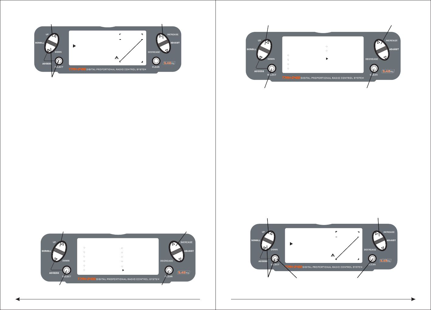
51 52
◇To Enter the Function Mode
● Turn the transmitter on.
● From the main screen press the DOWN and SELECT keys simultaneously.
● The system is now in Function Mode and will display the last screen that was
used in Function Mode.
◇To Exit the Function Mode
● Press the DOWN and SELECT keys simultaneously. The system will return to
the main screen.
◆List Modes
The list mode screens display all the functions on screen, allowing the access of
any function without having to scroll through each screen. Note that there are two
list modes: a System Setup list mode that displays all the system setup functions
and a Function list mode that displays all the system programming functions.
To enter the System Setup List Mode, with the system on and in any System Setup
function, press the UP and SELECT keys simultaneously.
To enter the Function List mode, with the system on and in any function mode screen,
press the UP and SELECT keys simultaneously.
In either List Mode, pressing the UP and DOWN keys will move the cursor to the
desired function. Then pressing the DOWN and SELECT key simultaneously will
access the selected function.
10.3 Function Mode Functions
◆Dual Rate and Exponential
The Dual Rate and Exponential function allows two control rates to be programmed
and selected with a switch. Dual rates and exponentials are available on the aileron
, elevator and rudder channels. Changing the dual rate value not only affects the
maximum control authority but also affects the overall sensitivity of control. A higher
rate yields a higher overall sensitivity.
Dual rates can be controlled by their respective dual rate switches (aileron, elevator
and rudder). An auto dual rate function is available that allows to automatic
selection of the desired rates via the three-position flight-mode switch.
Exponential values are adjustable from -100% to +100%. The factory default
settings for both the 0 and 1 switch positions are 100%. Either switch position may
be selected as the low or high rate by placing the switch in the desired position and
adjusting the value accordingly.
[FUNCTION LIST]
D/R & EXP
AUTO D/R
SWASH MIX
REV. SW
SUB TRIM
TRAV ADJ.
PI CURV ST1
THRO HOLD
TH CURV NOR
TH CURV ST1
TH CURV ST2
PI CURV NORASE and DECREASE key
UP and DOWN key
SELECT key CLEAR key
PI CURV NOR
INCREASE and DECREASE key
[FUNCTION LIST]
PI CURV ST2
PROG.MIX2
REVO. MIX
GYRO SENS
PROG.MIX1
PROG.MIX3
TIMER
UP and DOWN key
SELECT key CLEAR key
MONITOR
[D/R & EXP]
POS-0
AILE
D/R 100%
EXP LIN
OUTPUT
Press to adjust value
Press to enter DUAL
Press to enter
Function Mode
RATE and EXPONENTIAL
Press to select
desired function
Press to return value
to default setting
[D/R & EXP]
POS-0
D/R 100%
EXP LIN
OUTPUT
INCREASE and DECREASE keyUP and DOWN key
Press to enterFunction Mode
AILE
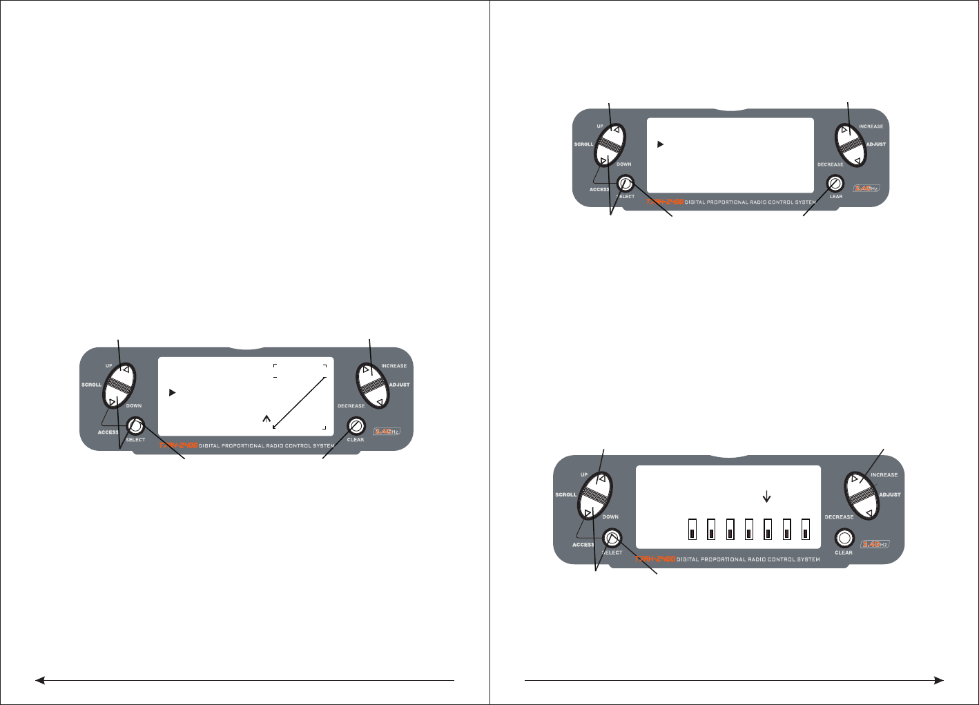
53 54
The Exponential function allows two exponential rates to be programmed and
selected with a switch. Exponential is available on the aileron, elevator and rudder
channels. Changing the exponential value does not affect the maximum control
authority but only affects control sensitivity. Exponential is normally used to reduce
control sensitivity around neutral while still allowing high control authority at the
extremes of throw. The sensitivity around center can be tailored using the
Exponential function to precisely adjust control feel.Exponential rates can be
controlled by their respective rate switches (aileron, elevator and rudder),
or combined on a flight mode switch. Exponential is available for the aileron,
elevator and rudder channels. Expo values are adjustable from -100% (full negative
expo), LIN (linear), and +100% (full positive expo). The factory default settings for
both the 0 and 1 switch positions are LIN or 0%. Either switch position may be
selected to give any desirable EXPO rate by placing the switch in the desired
position and adjusting the value accordingly.
Note: A negative (-) Expo value will increase sensitivity around neutral, and a
positive (+) Expo value will decrease sensitivity around neutral. Normally a
positive value is used to insensitize control response around neutral.
◇To Adjust the Exponential
Press the DOWN and SELECT keys simultaneously to access the Function Mode.
In Function Mode, use the UP or DOWN keys to select the DUAL RATE AND
EXPONENTIAL screen.Press the INCREASE or DECREASE key to select the
desired channel (AILE, ELEV or RUDD).Move the selected channel's dual rate
switch to the desired position, 0 or 1.Press the SELECT key until EXP is highlighted.
Adjust the Expo rate values for the selected switch position using the INCREASE
or DECREASE keys.
◆Auto Dual Rate EXP
The Auto Dual Rate and Expo function allows Expo and Dual Rate values (aileron,
elevator and rudder) to be automatically selected in each flight mode (Normal,
◇To Adjust the Auto Dual Rate
Press the DOWN and SELECT key simultaneously to access the Function Mode.
Press the UP or DowN key until the AUTO D/R EXP screen appears on screen.
Use the select key to select NORMAL, ST1 ST2 or NORMAL mode.
When selected, press the INCREASE or DECREASE key to select DUAL RATE,
P-1, P-2 or INHIBIT.
Note: The actual dual rate values are setted in the Dual Rate and Expo screen.
See Page 84.
◆Reverse Switch
The Reverse Switch function allows electronic means of reversing the servo’s throw.
Servo reversing is available for all seven channels.
◇Accessing the Reverse Switch Function
Press the SELECT key to access the desired channel.
Press the INCREASE or DECREASE keys to reverse the servo direction for that
selected channel.
[D/R & EXP]
POS-0
AILE
D/R 100%
EXP LIN
OUTPUT
Press to adjust value
Press to enter DUAL
Press to enter
Function Mode
RATE and EXPONENTIAL
Press to select
desired function
Press to return value
to default setting
[AUTO D/R & EXP]
NORM INH
ST-1 INH
Press to adjust value
Press to enter
Press to enter
Function Mode
Press to select
desired flight mode
Press to return value
AUTO DUAL RATE
to default setting
ST-2 INH
[REVERSING SW]
NORM
GEAR
ch 1 2 3 4 5 6 7
REV.
Press to select REV. or NORMPress to enter REVERSE
Press to enter
Function Mode
Press to select
desired channel
St1, ST2, and Hold.) When an auto dual rate flight mode is inhibited, the dual rate
is defaulted to the correlating switch and dual rate switch positions.
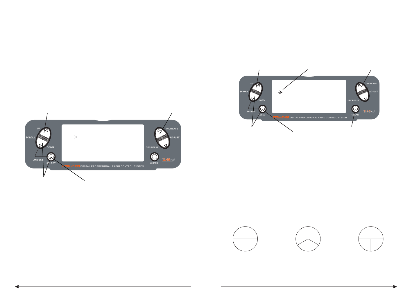
55 56
● THRO: Throttle ● AILE: Aileron ● ELEV: Elevator ● RUDD: Rudder
● GEAR: Gyro Gain ● PIT: Pitch (AUX1) Gyro Gain
◆Sub Trim
The Sub-Trim function allows you to electronically adjust the centering of each
servo. Sub trim is individually adjustable for all seven channels, with a range of +
or - 125% (+ or – 30 degrees servo travel).
Caution: Do not use excessive sub-trim values as it is possible to overdrive the
servo’s maximum travel. Sub-trim value (max ±125).
The available channels are:
● THRO: Throttle ● AILE: Aileron ● ELEV: Elevator
● RUDD: Rudder ● GEAR: Retractable Landing Gear
● PIT.: Pitch ● AUX2: Auxiliary 2
◇To Access the Sub-Trim Function
Press the DOWN and SELECT keys simultaneously to access the Function Mode.
In Function Mode, use the UP or DOWN key to select the SUB TRIM screen.
Press the SELECT key to access the desired channel.
Press the INCREASE or DECREASE keys to adjust the sub-trim position for that
selected channel.
● ELEV: Elevator
● RUDD: Rudder
● GEAR: Retractable Landing Gear
● PIT.: Pitch
● AUX2: Auxiliary 2
◇To Access the Travel Adjust Function
Press the SELECT key to access the desired channel.
Move the selected channel’s Stick or switch in the desired direction that you wish
to adjust.
◆The screen of the swash mix only showes when is activited. swash mix can
adjust the quantity and direction of the aileron trip,elevator and rudder.For example
,if more aileron trips are selected ,adding the mixed value will increase the necessary
whole trip of steer to get more aileron distance.
NOTE: The use of a negative value will reverse the direction of the function
2 Servo/180 CCPM 3 Servo/120 CCPM
(most popular) 3 Servo/90 CCPM
Ch6Ch2
Ch3
Ch2 Ch6
Ch3
Ch2 Ch6
Press to enter SUB TRIM Press to adjust sub-trim position
Function Mode
Press to enter
[ SUB TRIM ]
Press to select
Desired channel
THRO AILE
0 0
ELEV RUDD
0 0
[TRAVEL ADJUST]
THRO
H 100%
L 100%
ELEV
D 100%
U 100%
AILE
L 100%
R 100%
RUDD
L 100%
Selected channel
Press to enter
TRAVEL ADJUST
Press to enter
Function Mode
Press to return
value to default
Press to select
desired channel
R 100%
Press to adjust value
◆Travel Adjust
The Travel Adjust function allows the precise end point adjustments of all seven
channels in each direction independently. The travel adjust range is from 0–125%.
Channel available for programming are:
● THRO: Throttle
● AILE: Aileron
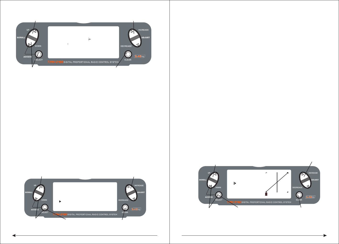
57 58
◇Accessing the Swashplate Mix Function
Press the DOWN and SELECT keys simultaneously to access the Function Mode.
In function mode, press the UP or DOWN key to select the SWASH MIX screen.
Press the SELECT key to access the desired function (AILERON, ELEVATOR,
PITCH or EXPO).Press the INCREASE or DECREASE key to change the selected
swashplate mix value.
Note: Selecting a negative value will reverse the direction of the function.
Note:The cross plate's exponential function can be used,the compensation for non
linear output is caused by the loop servo's rotation. The exponential function can
eliminate the cross plate interaction in extreme times.
◆Throttle Hold
The Throttle Hold function is used to practice autorotation and is often use as a
safety switch for electric helicopters, holding the throttle in the off position. When
the throttle hold switch is activated, the throttle hold function holds the throttle
servo/ ESC in a specific position (normally low or off throttle) while all other servos
function normally. The throttle hold switch is also selectable. Switch selection
options include rudd D/R, gear, AUX2, aileron D/R or elevator D/R.
◇To Access the Throttle Hold Function
Press the DOWN and SELECT keys simultaneously to access the Function Mode.
In Function Mode, use the UP or DOWN key to select the THRO HOLD screen.
Press the INCREASE or DECREASE key to activate the throttle hold function.
When activated, press the INCREASE or DECREASE key to change the throttle
hold value.
◇To Access the Throttle Hold Switch Function
Press the SELECT key to highlight switch.
Press the INCREASE or DECREASE key to select the desired switch.
◆Throttle Curve
The T7AH-2400 offers three (3) separate throttle curves with five (5) adjustable
points per curve. This function allows you to adust the throttle curve to optimize
engine rpm at a particular pitch setting. Once the throttle curves are established,
each can be activated in flight using the 3-position flight mode switch. The flight
mode switch offersthree (3) selectable curves: N=Normal, 1=Stunt 1, 2=Stunt 2.
The N, or Normal, position should be used for starting the engine and hovering.
Positions 1 and 2, or Stunt 1 and Stunt 2, should be used for aerobatic maneuvers
and forward flight.
Note: The throttle trim and hovering throttle lever are only operable when the flight
mode switch is in the Normal position. Thus, in the 1 or 2 positions, these two
functions have no effect. Each of the five (5) positions of the throttle curve are
independently adjustable from 0–100%. These five (5) positions correspond to
the position of the throttlestick.The transmitter is factory preset to the throttle
curve as indicated by the solid line in the figure below. Individual points can be
activated and increased/decreased to suit your specific needs.
◇To Access the Throttle Curve Function
Press the DOWN and SELECT keys simultaneously to access the System Mode.
Press to enter SWASH MIX Press to adjust value
Hold white turning
on the transmitter
[SWASH MIX]
3 SERVO
120
EXP INH
AILE+ 60%
ELEV+ 60%
PIF. + 60%
Press to reset
value to default
[THRO HOLD]
SW:RUDD D/R
HOLD POS. -5.0%
Press to enter
THROTTLE HOLD
Press to enter
Function Mode
Press to return
value to INH
Press to select
desired channel
Press to activate THROTTLE HOLD
and change values
Press to adjust values
[THRO CURVE]
NORM
Point-L
51 51
0.0%
1 2 3 HL
IN OUT
Press to enter
THROTTLE CURVE
Press to enter
Function Mode
Press to select
desired points
Press to return
value to default
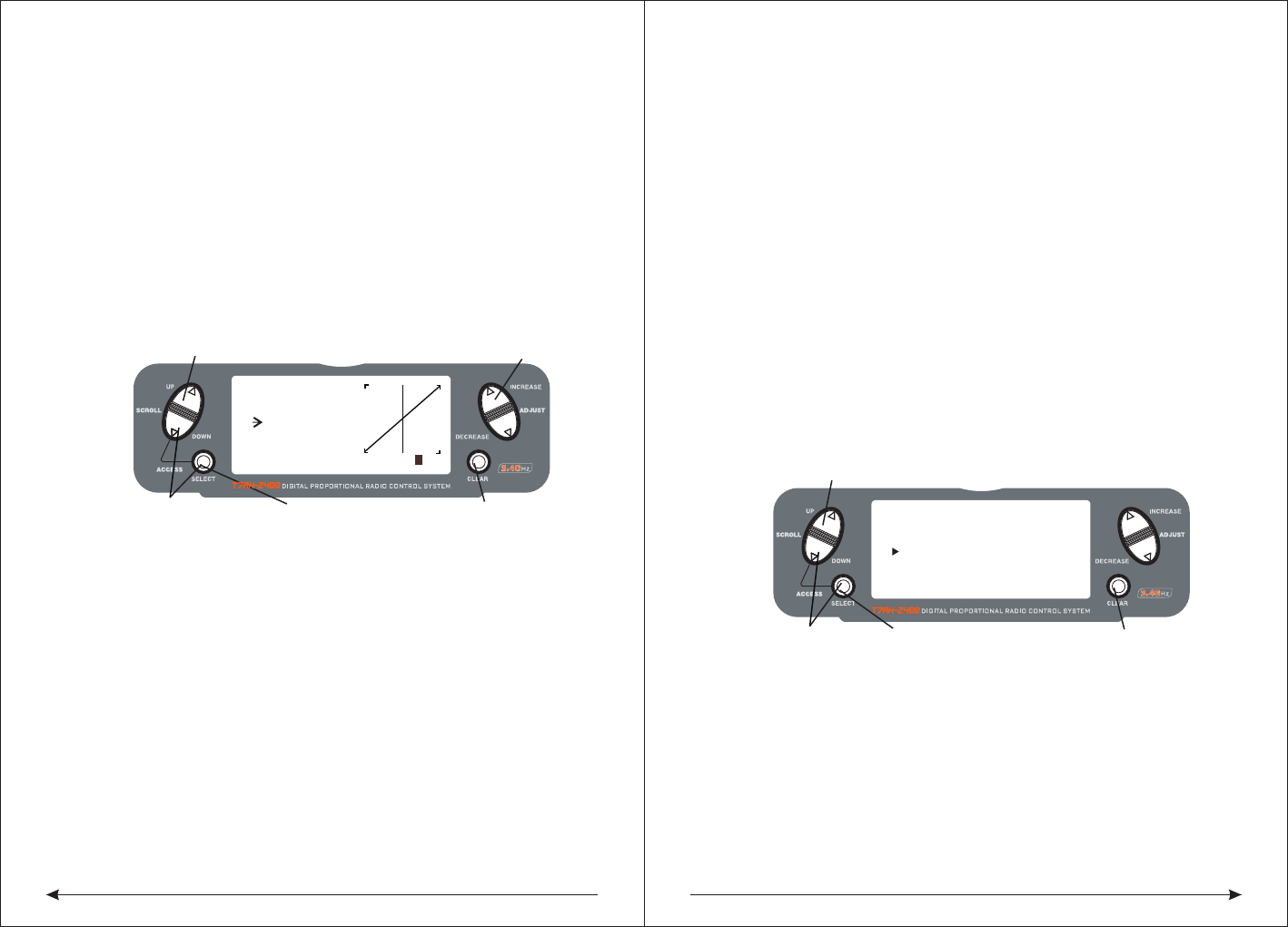
59 60
◆Pitch Curve
Adjustment of the pitch curve is very similar to the throttle curve adjustment
described in the preceding section. A thorough understanding of the throttle curve
section will make pitch curve adjustment easier to understand.
The T7AH-2400 offers four (4) independent pitch curves: Normal, Stunt 1, Stunt 2
and Hold. Each pitch curve contains five (5) adjustable points — L, 1, 2, 3, and H.
Note: When setting pitch curve for throttle hold, it is necessary for the throttle hold
to be active. if this function is inhibited, the throttle hold pitch curve will not be
visible on the screen.
◇To Access the Pitch Curve Function
Press the DOWN and SELECT keys simultaneously to access the System Mode.
In System Mode, use the UP or DOWN keys to select the PITCH CURVE NORM
screen. Press the SELECT button to access pitch points L (Low), 1, 2, 3, or H
(High) or EXPO.Press the INCREASE or DECREASE keys to change the selected
pitch value or expo on/off.
◆Hovering Pitch Rocker
The hovering pitch rocker operates in the same manner as the hovering throttle
rocker. It is operable while the flight mode is in the N, or Normal, position, and its
function is to shift the center point (#2) of the curve either upward or downward to
adjust pitch at the hover position.
◆Revolution Mixing (only used with non-heading hold gyros)
The Revolution Mixing Function mixes tail rotor input with the Throttle/Collective
function to counteract torque from the main rotor blades. When set up correctly,
the helicopter should climb and descend without a tendency to yaw in either
direction. Because torque reaction varies with different power settings, it is
◆Setting Up Revolution Mixing
First, adjust the helicopter so that it will hover in a neutral position with the tail rotor
trim at center. Next, establish the helicopter into a stable hover; then steadily
increase the throttle to initiate a stable climb. The body of the helicopter will move
in the opposite direction to the main rotor rotation. Increase the U, or Up, setting
until the helicopter will climb with no tendency to turn or rotate. At a safe altitude,
close the throttle and the helicopter will descend with the body turning in the same
direction as the main rotor. Increase the D, or Down, mix until the helicopter
descends with no tendency to turn or rotate. When attempting this procedure,
throttle stick movements should be slow, and the initial acceleration and
deceleration swings should be overlooked.
。
◇To Access Revolution Mixing
Press the DOWN and SELECT keys simultaneously to access the Function Mode.
Press the SELECT key to select the desired function.
Press the INCREASE or DECREASE key to change the value or function.
◆Gyro Sensing
The T7AH-2400 offers two different types of Gyro Sensitivity Adjustments — manual
or automatic. This feature gives the user the choice of selecting gyro sensitivity
manually through the rudder dual rate switch or automatically through the flight
mode switch.
[ REVO MIX ]
Press to enter REVO MIX
Press to enter
Function Mode
Press to select
desired channel
Press to return
value to default
NORM STNT
UP 0% UP 0%
DN 0% DN 0%
Press to adjust values
[PITCH CURVE]
NORM
Point-3
51 51
INH
1 2 3HL
IN OUT
Press to enter
THROTTLE CURVE
Press to enter
Function Mode
Press to select
desired points
Press to return
value to default
In System Mode, use the UP or DOWN keys to select the THRO CURVE NORM
screen.Press the SELECT button to access pitch points L (Low), 1, 2, 3, or H (High)
or EXPO.Press the INCREASE or DECREASE keys to change the selected pitch
value or expo on/off.
necessary to vary the tail rotor pitch at the same time. The DX7 offers two (2)
separate revolution mixing programs with independent up and down mixing for
each—one for flight mode position N, and the other for Stunt 1 and Stunt 2
positions. The U, or Up, mixing adjusts the tail rotor compensation for the mid to
high throttle/stick setting, and the D, or DOWN, mixing adjusts the tail rotor
compensation for the mid to low throttle/stick setting.In the Function Mode, use
the UP or DOWN keys to select Revolution Mixing screen.!!
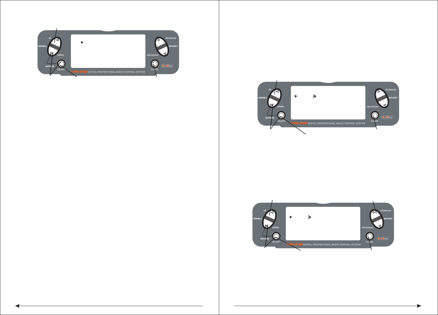
61 62
◇To Access the Gyro Sensing Function
In function mode, press the UP or DowN key until gYRO SENS screen appears on
the screen.Use the SELECT key to highlight the desired RATE or FLIgHT MODE.
Press the INCREASE or DECREASE key to change the rate value or the select
position 0 or 1 for each flight mode.
Note: In order to access the Gyro Sensing function, it is necessary to select Gyro
in the Input Select screen and assign it to AUX2 or the gear channel. See Page
78 for more details.
◆Manual Gyro Sensitivity Adjustment
Manual Gyro Sensitivity Adjustment allows the pilot to select from two different
gyro sensitivities during all flight conditions. This function is activated in
conjunction with the rudder dual rate switch.
◆Automatic Gyro Sensitivity Adjustment
The Automatic Gyro Sensitivity Adjustment feature allows the pilot to automatically
alter the sensitivity of the gyro from either of two pre-determined settings through
the use of the flight mode switch. As different flight modes are selected (Normal,
1, 2, Hold), the Gyro’s sensitivity rate will switch to the pre-determined com
pensation rate for each particular flight mode in use. [ PROG.MIX1 ]
Press to enter PROG MIX
Press to enter
Function Mode
Press to return
value to default
RATE: 0%
SW:ON 0%
THRO THRO ON
OFFSET: 0
Press to highlight
Press to adjust mix value
RATE
[ PROG.MIX1 ]
Press to enter GYRO SENS
Press to enter
Function Mode
Press to return
value to default
RATE: 0%
SW:ON 0%
THRO THRO ON
OFFSET: 0
Press to highlight
MASTER CHANNEL
or SLAVE CHANNEL
[ ]GYRO SENS
Press to enter GYRO SENS
Press to enter
Function Mode
Press to select
desired function
Press to return
value to default
RATE:
1:50%
0:50%
AUTO F.MODE
NORM:0
STNT:0
◆Programmable Mixing 1–3
In helicopter mode the T7AH-2400 offers three (3) programmable mixes that allow
stick or switch inputs to control the output of two or more servos. This function
allows mixing any one channel to any other channel or the ability to mix a channel
to itself. The mix can remain ON at all times, or be switched OFF in flight using a
number of different switches. (Refer to chart below.) Mix values are adjustable
from 0 to 125%. Each channel is identified by a four-character name (i.e., Aileron -
AILE, Elevator - ELEV, etc.). The channel appearing first is the master channel.
The second channel is the slave channel. For example, AILE - ELEV would indicate
aileron-to-elevator mixing. Each time the aileron stick is moved, the elevator will
deflect, and the elevator will automatically move in the direction and to the position
based on the value input in the programmable mix screen. Mixing is proportional,
so small inputs of the master channel will produce small outputs of the slave
channel. Each programmable mix has a mixing offset. The purpose of the mixing
offset is to redefine the neutral position of the auxiliary channel.
● ON: Mixing always on ● F-NR: Flight mode normal
● F-S12: Stunt modes 1 and 2 ● F-S2: Stunt mode 2
● HOLD: Throttle hole toward self ● GEAR: Gear channel toward self
◆Assigning Channels
Press the DOWN and SELECT keys simultaneously to access the Function Mode.
In Function Mode, use the UP or DOWN keys to select the desired PROG. MIX
screen (1–3). Press the INCREASE or DECREASE button to access the
Programmable Mix function.Press the INCREASE or DECREASE keys to select
the desired master channel.Press the SELECT key to highlight the auxiliary channel.
Press the INCREASE or DECREASE keys to select the desired slave channel.
◇Assigning Mixing Values
Press the DOWN and SELECT keys simultaneously to access the Function Mode.
In Function Mode, use the UP or DowN keys to select the desired PROg. MIX
screen (1–3).Press the SELECT key to highlight RATE.
Using the stick or switch that is assigned to the master channel, move that stick or
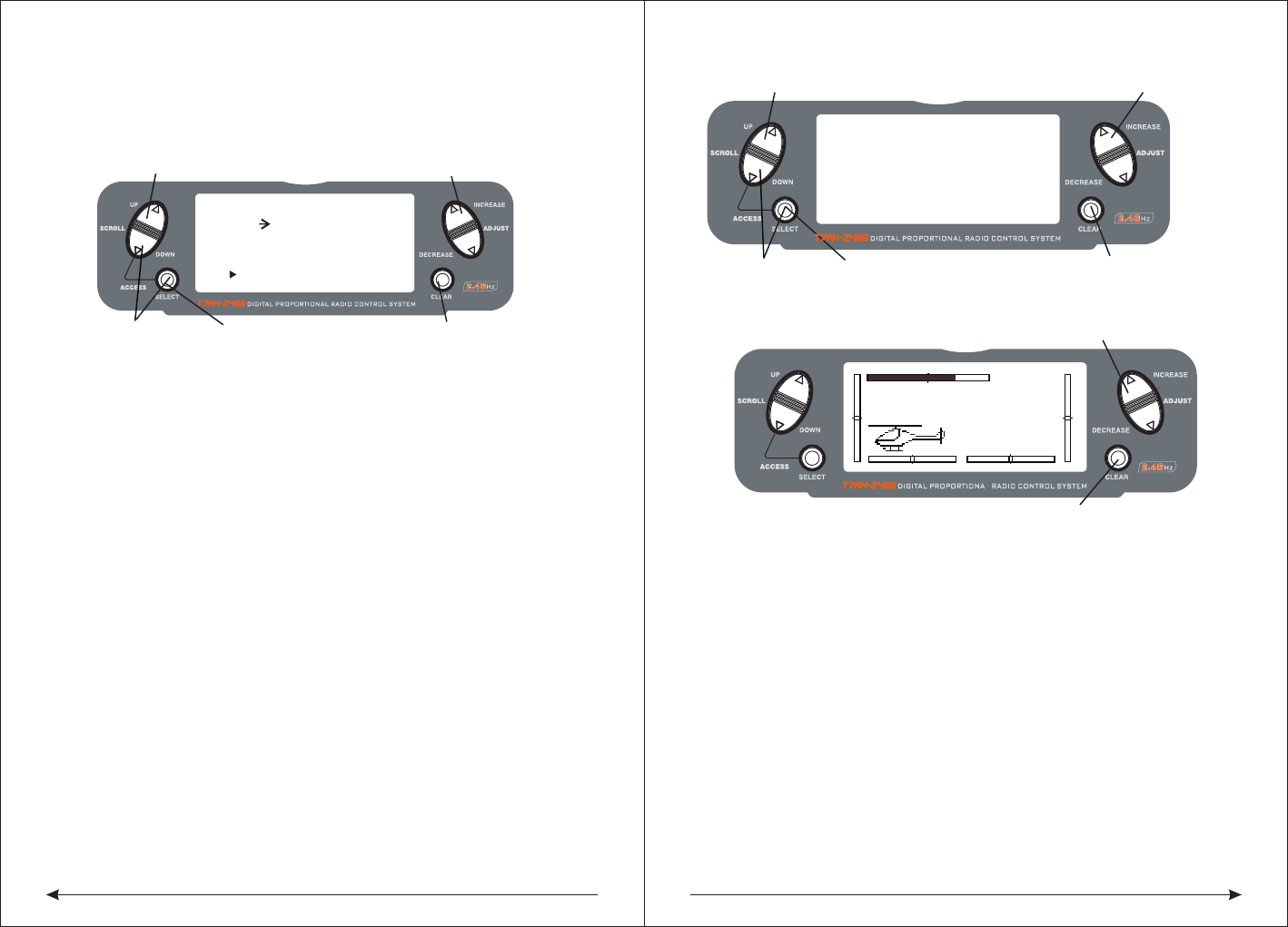
63 64
MODEL 110.6V
12.5ms FRAME RATE
DOWN-T
10:00
Press the INCREASE or DECREASE
Press the CLEAR key to reset the timer
key to start or stop the timer
Press to select TIMER
Press to enter
Function Mode
Press the CLEAR key
to reset the DOWN-T
to 10:00 minutes
Press the SELECT key
to access INH, DOWN-T
or STOP-W
Press the INCREASE or DECREASE
key to set the down timer
[ TIMER ]
MODEL 1
DOWN-T
00:00
SW:ADJUST
[ PROG.MIX1 ]
Press to enter PROG MIX
Press to enter
Function Mode
Press to return
value to default
RATE: 0%
SW:ON 0%
THRO THRO ON
OFFSET: 0
Press to adjust mix value
Press to
highlight OFFSET
switch in the desired direction that you wish to adjust the mix value. Press the
INCREASE or DECREASE keys to adjust the mix value.
Note: If a switch is assigned to the mix, that switch must be turned on to allow
mixing values to be changed.Moving the stick or switch in the opposite direction
will allow the mix value to be adjusted in the opposite direction.
◆Assigning an Offset
Press the DowN and SELECT keys simultaneously to access the Function Mode.
In Function Mode, use the UP or DOWN keys to select the desired PROG. MIX
screen (1–3).Press the SELECT key to highlight OFFSET.
Press the INCREASE or DECREASE key to select the desired offset value.
◆Timer
T7AH-2400 provides a screen show timer.with three programmable Settings
INH:Shielding-in this mode timer is closed
DOWN-T:
Countdown timer-decreasing order of default timer which allowed 10 seconds of
interval to 59 points 50 seconds was programming. When that time expires before
10 S, every 1 S have a sound, a total of 10 times.
STOP-W:
Stopwatch-a stopwatch function is a simple count timer, display up to 59 points 59]
seconds. When that time expires, the top 10 S. Every 1 s have a sound, a total of
10 times
When the countdown timer and stopwatch function is selected, the timer will
display in the main screen. The following button or switch is to start or stop the timer.
SW: ADJUST ADJUST button
FLTNOR Flight mode NORMAL ELE D/R Elevator double proportion
GEAR GEAR AUX2 AUX2 AILE D/R Aileron double proportion
RUDD D/R Direction listed the campaign of THROHOLD Throttle keep
CLEAR buttons:
Used to reset timers to the default time or reset a stopwatch to 0-0
FLT12 Flight mode 1、2
◇Access to the timer function
Press the DOWN and SELECT buttons simultaneously to enter the system mode.
In system mode, the use UP or DOWN keys to select the timer screen
According to the SELECT button to choose a stopwatch, countdown timer or stop
After choosing the countdown timer press INCREASE or DECREASE button to
change the programming in advance.
◇Access the timer control buttons or switch function
Press the SELECT and the DOWN buttons simultaneously to enter the system mode
In system mode, to use UP or DOWN keys to select the TIMER screen.
Press the SELECT button to choose SW,,start or stop the timer buttons or switch
After choosing the SW and then to press INCREASE or DECREASE keys to
selector buttons or switch.
Server display
Server display screen is used as a useful tool when programming your remote
control. It shows the steering gear's moving and direction when different
programming function, the joystick or switch moves.
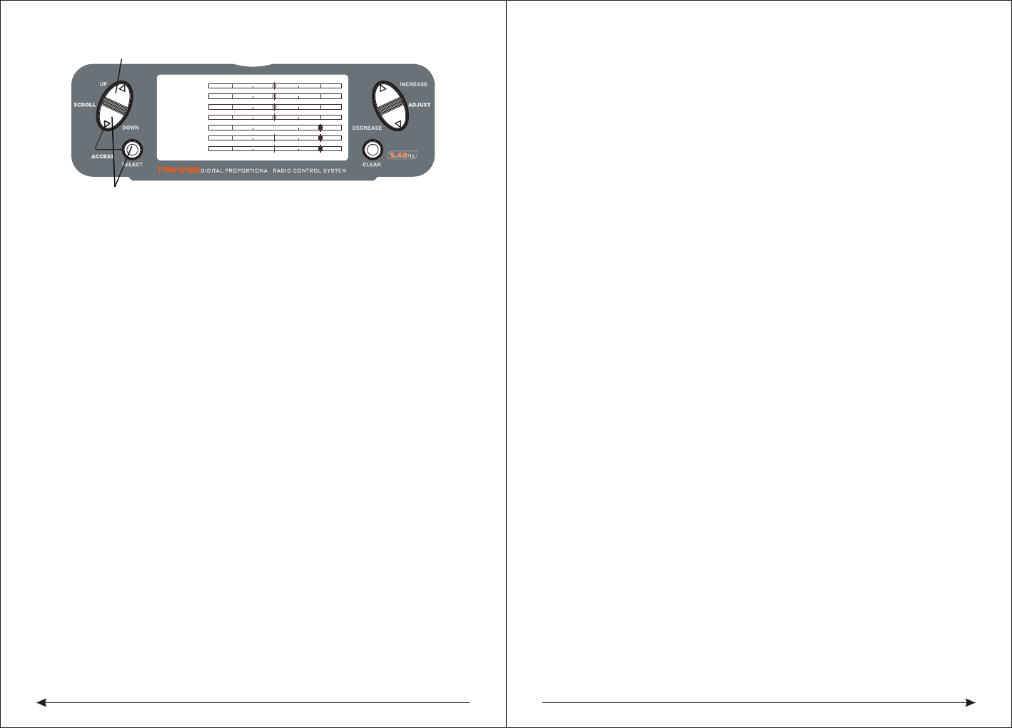
65 66
The related safety issue
◆servo prevention measures
●Don't add the oil to lubricate the steering gear or the motor.
●In the withdrawn or extensions of the conditions don't let the steering gear run
overload.be sure they could be in full deflection operation.
●Ensure that all of the steering gear running freely, no connected or bound aside.
A bind of the control connection will lead the steering gear. to cost excessive
current . A stall of the steering gear can be in just a few minutes for draining batteries.
●Once be noticed in the flight, correct any control surfaces.Because this condition
could damage the Partial pressure gauge in the steering engine.Ignore the beating
buzz or beating flyingis very dangerous.
●When installing steering gear, use the rubber gaskets and provide brass servo
gasket,Don't put the steering gear installed screws too tight, because this will make
rubber gasket inhibition invalid.
●To ensure the safety of the servo arm fixed in the steering gear.
●Do not use steering gear arm when the steering gear arm turn to yellow or
decoloration .The steering gear arm is a fragile, at any time could suddenly be
rupture, and it could well lead to a plane crash.
●Often check all related install screw and link. The vibration of plane is due to
link or often too loose screw.。
◆General descriptions
Remote control model is the source of joy.But if we do not have the right way to run
or good maintenance words they can also cause the potential risk.
It is very important to fix your system right. In addition,your professional ability need
to be enough to control the plane.if you were a new hand ,please learn the
experience from the old hand , or the local shop.
◆Safety knowledge
●Be sure you battery have the right charging in the first fight.
●Tracking at any time your system is on,and then you could know how long your
THRO
AILE
ELEV
RUDD
GEAR
PIT.
AUX2
Press to enter SERVO MONITOR
Press to enter Function Mode
system could last .
●Before the first flying ,check the Underside distance,please have a look at the daily
flight check chapter.
●Before flying ,check all the appearance control .
●Don't fly in the public, parking lot or other personal property losses.
●Don't fly in the bad weather.Very poor visibility can lead to problems or the plane
out ofcontrol of the direction.strong wind also can lead the same problem.
●Don't risk.when flying ,you notice the Unstable or abnormal situation.
◆Standard operation
The model is concerned with the flying model plane's security issues and good
judgment. But in view of safety, we encourage the operators of the remote control
model and free flight to comply with the following standards
1. In order to avoid the cash ,please be serious to the big plane.
2 .In order to avoid the noisy problem and the potential danger ,please find a place
which is far away from the settlement place.
3. Don't fly higher 400m than the ground
4 .Don't fly near the airport.
◆ Routine flight check
1. Check the battery voltage ,transmitter and receiver. Don't let the transmitter be less
than 9.0 V and receiver be less than 4.7 V, when the flight. Doing so may destroy the
plane.
2 .Check all the hardware(Connect, screws, nuts and bolts),before flying ,be sure
that it will not have parts loose phenomenon to appear).
3 .Appearance check ensures that all movement part normal activities.
4 .Every time before flying ,you need to check the control distance on the ground,if it
is normal or not.
5 .Check all the hardware(Connect, screws, nuts and bolts),before flying ,be sure
that it
Before the plane taking off,turn off your transmitter and then turn on ,Every time,you
need to do like this before the plane taking off.
6 .Check all the fine tuning of leverage is in the correct posit
7. All of the servo plugs must be firmly into the receiver
◆Model matching
The transmitter can respectively memory 8 kinds of fixed wing and 8 kinds of various
models of the helicopter parameter Settings. Never can incorrectly use memory
function to take off and memory unmatched model. This may make model crash.

FCC warning:
This device complies with Part 15 of the FCC Rules. Operation
is subject to the following two conditions: (1) this device may
not cause harmful interference, and (2) this device must accept
any interference received, including interference that may cause
undesired operation.
changes or modifications not expressly approved by the party responsible for compliance
could void the user's authority to operate the equipment.
NOTE: This equipment has been tested and found to comply with the limits for a
Class B digital device, pursuant to Part 15 of the FCC Rules. These limits are
designed to provide reasonable protection against harmful interference in a
residential installation. This equipment generates, uses and can radiate radio
frequency energy and, if not installed and used in accordance with the
instructions, may cause harmful interference to radio communications. However,
there is no guarantee that interference will not occur in a particular installation.
If this equipment does cause harmful interference to radio or television reception,
which can be determined by turning the equipment off and on, the user is
encouraged to try to correct the interference by one or more of the following
measures:
-- Reorient or relocate the receiving antenna.
-- Increase the separation between the equipment and receiver.
-- Connect the equipment into an outlet on a circuit different
from that to which the receiver is connected.
-- Consult the dealer or an experienced radio/TV technician for help.
RF warning statement:
The device has been evaluated to meet general RF exposure requirement. The device
can be used in portable exposure condition without restriction.