Xingyaohua U8XYHMOTOR Remote Control Model User Manual Rev
Shenzhen Xingyaohua Industrial Co., Ltd. Remote Control Model Rev
Users Manual
T3G-2400 Instruction Manual for Radio Control System
一、Overview
T3G-2400 aeromodelling radio is a pistol remote control equipment exclusively for vehicle
aeromodelling and boat aeromodelling. It can be used both on electronic and nitro vehicle
aeromodelling or boat aeromodelling .The radio has two ratio channels and one switch
channel .And many sets of equipments can be used at the same time without interference.
Main Performance for Transmitter
working power: 4s of common 5 # Alkaline Battery or Ni-MH chargeable battery
working current:<35mA
Transmission Frequency: 2400MHz (FHSS)
Code Format : PCM
Indicating Mode for adjusting channel’s midpoint and servo: LED
Working power for receiver 4.8V-6V
二、Instruction
1. Each transmitter of T3G-2400 remote control equipment has a sole address code. The receiver
must be matched with it before usage.
Method: turn on the transmitter and receiver, the green indicating light of receiver begins to flas
(as picture 2).Press the ID CODE switch of the receiver for more than 4~5 seconds. It is
indicating that the receiver has the right ID CODE with transmitter when the green indicating light
of the receiver is lighting .At this time the receiver is only controlled by the transmitter aligned
with its code and can not be controlled or interfered by other transmitters .Please note that there is
no transmitter with the same kind open when aligning the code or it will fail.
2.Channel control for transmitter
As(picture 1)
12 is the control wheel of CHI (first channel).It can be rotated for 30 angles clockwise or
counterclockwise respectively.
14 is the control trigger of CH2 (Second channel).It can be pulled backward or pushed forward.
10 is the control switch of CH3 (Third channel).It is a switch channel.
Adjustment for midpoint of the servo
6 and 7 (picturer1) are the reverse switch of CH1 and CH2 respectively. 11 and 13 are the
adjusting buttons for the channel’s midpoint of CH1 and CH2. Both of the buttons can be pushed
clockwise and counterclockwise. If 6 and 7 switch is put to the “NOR” position ,the red indicating
lights of 1 and 3 will lighten in line clockwise or counterclockwise according to the button’s push
direction when pushing the button 11or 13 and make ringing sound at the same time. The servo of
corresponding channel of receiver will also rotate a certain angle according to the corresponding
direction.
The green indicating lights of 1 and 3 (picture1) are the tolerant midpoint indication of CH1 and
CH2 respectively. And they are usually lighting It is indicating that the midpoint of the servo is
adjusted to the tolerant midpoint of the transmitter when all the red lights are adjusted to put out
by button 11 and 13
Adjustment for large and small servo angle
When Pressing the button 15 (picture 1), the green indicating light 2 lightens gradually and the
servo angle of CH1 will increase.
When Pressing the button 16 (picture 1), the green indicating light 2 becomes dim gradually until
put out and the servo angle of CH1 will decrease.
4 (picture 1) is the Power Switch.5 is Charging Jack .7 is Power Indicating Light. 9 is Antenna .
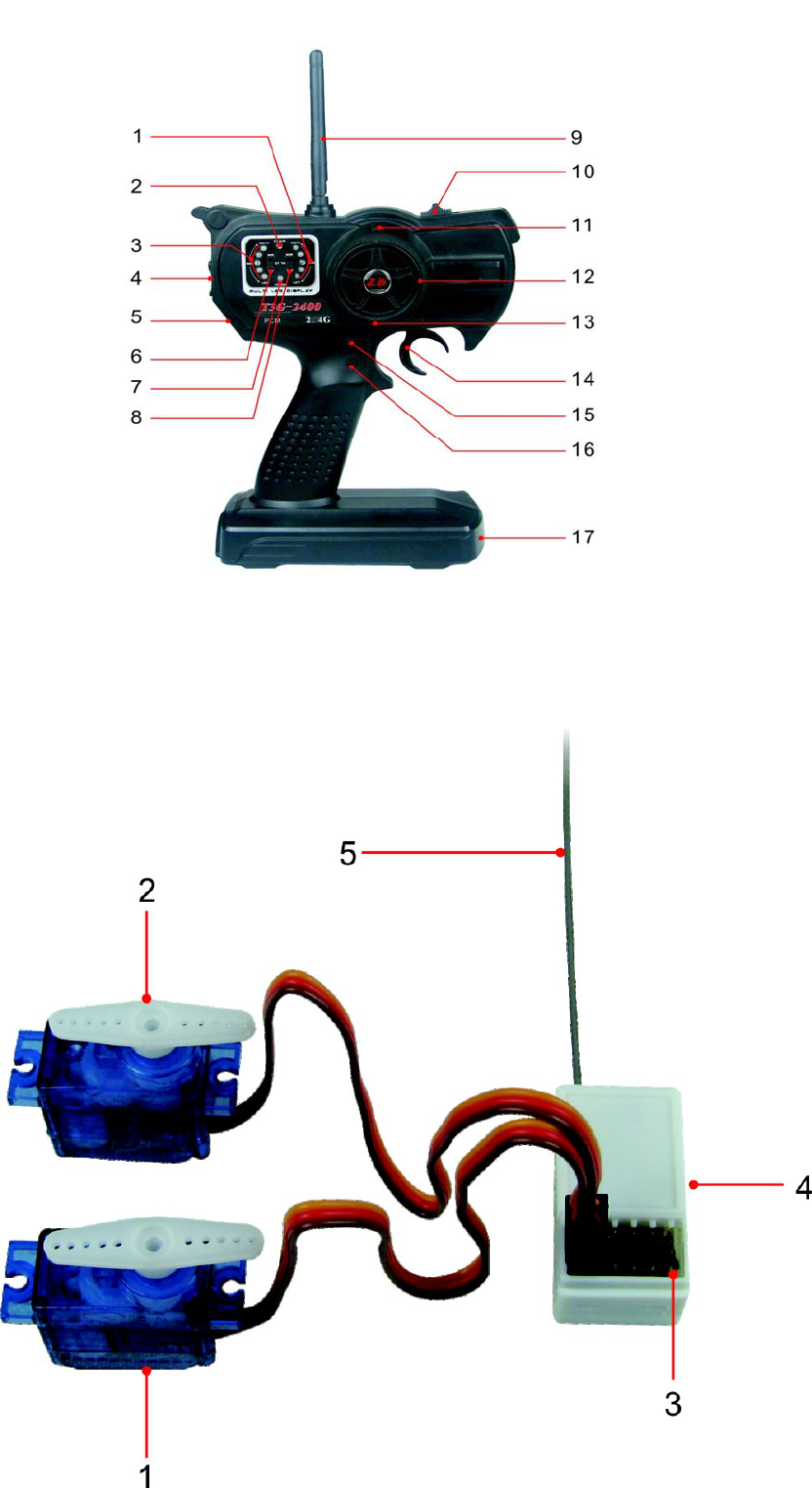
17 is Battery Box
(Picture 2 is receiver. 1 is CH1 servo (direction) .2 is CH2 servo (throttle) 3 is Power Jack. 4 is
the switch for ID code button. 5 is Antenna
FCC warning:
This device complies with Part 15 of the FCC Rules. Operation
is subject to the following two conditions: (1) this device may
not cause harmful interference, and (2) this device must accept
any interference received, including interference that may cause
undesired operation.
changes or modifications not expressly approved by the party responsible for compliance
could void the user's authority to operate the equipment.
NOTE: This equipment has been tested and found to comply with the limits for a
Class B digital device, pursuant to Part 15 of the FCC Rules. These limits are
designed to provide reasonable protection against harmful interference in a
residential installation. This equipment generates, uses and can radiate radio
frequency energy and, if not installed and used in accordance with the
instructions, may cause harmful interference to radio communications. However,
there is no guarantee that interference will not occur in a particular installation.
If this equipment does cause harmful interference to radio or television reception,
which can be determined by turning the equipment off and on, the user is
encouraged to try to correct the interference by one or more of the following
measures:
-- Reorient or relocate the receiving antenna.
-- Increase the separation between the equipment and receiver.
-- Connect the equipment into an outlet on a circuit different
from that to which the receiver is connected.
-- Consult the dealer or an experienced radio/TV technician for help.
RF warning statement:
The device has been evaluated to meet general RF exposure requirement. The device
can be used in portable exposure condition without restriction.