Xircom EAG2919 Eagle II 900/1900 MHz GSM Radio Module User Manual
Xircom Eagle II 900/1900 MHz GSM Radio Module Users Manual
Xircom >
Users Manual
© 2000 Xircom, Inc. All rights reserved.
All trademarks and copyrights are the property of Xircom, Inc.
Formerly Omnipoint Technologies, Inc.
Eagle™ II
GSM Radio Module
Wireless GSM Communication
Technical Manual
Eagle II GSM Radio Module Technical Manual Preliminary Draft: 08/31/00 2
Part Number: 07100017 version 00.04
© 2000 Xircom, Inc. All rights reserved.
All trademarks and copyrights are the property of Xircom, Inc.
SAFETY PRECAUTIONS
Important Safety Information
The following information applies to the devices described in this manual. Always
observe all standard and accepted safety precautions and guidelines when handling any
electrical device.
! Save this manual: it contains important safety information and operating instructions.
! Do not expose the Eagle™ II product to open flames.
! Ensure that liquids do not spill into the devices.
! Do not attempt to disassemble the product: Doing so will void the warranty. With the
exception of the Subscriber Identification Module (SIM), this product does not contain
consumer-serviceable components.
Guidelines for Limiting RF Exposure
The Eagle II products are GSM radio transceivers, which operate under the authority of
47 CFR Part 24, Subpart E of the FCC Rules and Regulations. When installed and
operated in accordance with the instructions provided in this manual, these devices
comply with current FCC regulations regarding human exposure to radio frequency
radiation.
The following installation and operation restrictions apply to all Eagle II products:
! This device may only be used in fixed and mobile applications.
! Portable applications, as defined by the FCC, are prohibited.
! The use of this device for desktop and other applications where the antenna can
easily be relocated are considered by the FCC to be mobile applications.
! A separation distance of at least 20 cm (7.87 inches) between the antenna and the
body of the user and other persons must be maintained at all times
! In FIXED applications, antenna gain is limited to a maximum of 7 dBi, with a
corresponding Equivalent Isotropic Radiated Power (EIRP) of 37 dBm / 5 W.
! In MOBILE applications, antenna gain is limited to a maximum of 3 dBi, with a
corresponding EIRP of 33 dBm / 2 W.
! End products must provide instructions to ensure compliance with radio frequency
radiation exposure requirements.
! A warning label visible to all persons exposed to the antenna and identical to that
described in this manual must be displayed on or next to the antenna.
! Separate FCC approval for RF exposure compliance is required for end products that
do not meet these conditions.
Antenna gain is defined as gain in dBi (dB referenced to an isotropic radiator) minus
cabling loss.

Eagle II GSM Radio Module Technical Manual Preliminary Draft: 08/31/00 3
Part Number: 07100017 version 00.04
© 2000 Xircom, Inc. All rights reserved.
All trademarks and copyrights are the property of Xircom, Inc.
Note: Additional care must be taken by the installer and/or user of the Eagle II
products to ensure proper antenna selection and installation. Adherence to the
above conditions is necessary to comply with FCC requirements for safe operation
regarding exposure to RF radiation.
Human Exposure Compliance Statement
Xircom, Inc. Wireless Technology Group certifies that the Eagle ™II 900/1900 MHz GSM
Radio Module (FCC ID: J3OEAG2919) complies with the RF hazard requirements
applicable to broadband PCS equipment operating under the authority of 47 CFR Part
24, Subpart E of the FCC Rules and Regulations. This certification is contingent upon
installation, operation and use of the Eagle ™ II and its host product in accordance with
all instructions provided to both the OEM and end used. When installed and operated in
a manner consistent with the instructions provided, the Eagle ™ II meets the maximum
permissible exposure (MPE) limits for general population / uncontrolled exposure at
defined in Section 1.1310 of the FCC Rules and Regulations.
Disclaimer
The information and instructions contained within this publication comply with all FCC,
NRTL, IMEI and other applicable codes that are in effect at the time of publication.
Xircom, Inc. disclaims all responsibility for any act or omissions, or for breach of law,
code or regulation, including local or state codes, performed by a third party.
Xircom strongly recommends that all installations, hookups, transmissions, etc., be
performed by persons who are experienced in the fields of radio frequency technologies.
Xircom acknowledges that the installation, setup and transmission guidelines contained
within this publication are guidelines, and that each installation may have variables
outside of the guidelines contained herein. Said variables must be taken into
consideration when installing or using the product, and Xircom, Inc. shall not be
responsible for installations or transmissions that fall outside of the parameters set forth
in this publication.
Xircom shall not be liable for consequential or incidental damages, injury to any person or
property, anticipated or lost profits, loss of time, or other losses incurred by Customer or
any third party in connection with the installation of the Products or Customer's failure to
comply with the information and instructions contained herein.
Eagle II GSM Radio Module Technical Manual Preliminary Draft: 08/31/00 4
Part Number: 07100017 version 00.04
© 2000 Xircom, Inc. All rights reserved.
All trademarks and copyrights are the property of Xircom, Inc.
CONTENTS
SAFETY PRECAUTIONS............................................................................................2
Important Safety Information.................................................................................................2
Guidelines for Limiting RF Exposure.....................................................................................2
Human Exposure Compliance Statement.............................................................................3
Disclaimer ..............................................................................................................................3
PRODUCT OVERVIEW...............................................................................................7
Bringing the Features of GSM Communications to an Application..................................7
Providing Multi-Band Operation........................................................................................7
Incorporating GSM Communications into the Design...........................................................8
Summary of the Features for the Eagle II Radio Module......................................................9
TECHNICAL SPECIFICATIONS................................................................................10
Physical Dimensions and Weight ...................................................................................10
Climatic: Operational.......................................................................................................10
Climatic: Storage and Transportation.............................................................................10
Mechanical: Operational .................................................................................................10
Mechanical: Storage and Transportation........................................................................11
Mechanical: Proposed Standards...................................................................................11
Electromagnetic Emissions............................................................................................. 11
Electromagnetic Immunity (per ETSI ETS 300 342-1)...................................................11
Operating Power .............................................................................................................12
Transmit Power...............................................................................................................12
Receiver Sensitivity.........................................................................................................12
Physical Layout for the Eagle II Module .........................................................................13
PHYSICAL INTERFACES OF THE EAGLE II MODULE ............................................14
Antenna Interface ................................................................................................................14
Input/Output (I/O) Signal Connector....................................................................................14
Mating Connector on the Carrier Board of the Application ............................................15
I/O Signal Connector on the Eagle II Module.................................................................15
I/O Connector Pin Assignments, Sorted by Functionality ..............................................15
Subscriber Identification Module (SIM) Carrier...................................................................18
Using a Remote SIM with the Eagle II Module...............................................................18
Status Indicator....................................................................................................................19
MODES OF OPERATION..........................................................................................20
Enabling the Transmission Modes for the GSM Services..............................................20
Eagle II GSM Radio Module Technical Manual Preliminary Draft: 08/31/00 5
Part Number: 07100017 version 00.04
© 2000 Xircom, Inc. All rights reserved.
All trademarks and copyrights are the property of Xircom, Inc.
Voice Communication..........................................................................................................20
Circuit-Switched Data..........................................................................................................20
SMS: Short Message Services............................................................................................ 21
SMS Features Supported by the Eagle II Module..........................................................21
General Packet Radio Service (GPRS) ..............................................................................21
PROVISIONING THE SIM .........................................................................................22
GSM Services Supported by the Eagle II Module..........................................................22
Selecting the Modes of Operation..................................................................................22
SOFTWARE INTERFACE OF THE EAGLE II MODULE............................................23
Format for the AT Commands............................................................................................. 23
AT Command Set ................................................................................................................23
Call Control Commands.................................................................................................. 24
GSM Network Commands..............................................................................................24
GSM Terminal Commands .............................................................................................24
AT Commands for SMS..................................................................................................26
S Registers......................................................................................................................26
Result Codes...................................................................................................................27
INITIALIZATION AND SETUP EXAMPLES...............................................................28
Initial Response to the AT Command .................................................................................28
Sending an Initialization String to the Eagle II Module .......................................................29
Setting Up the Communication Mode for the Eagle II Module............................................29
Querying the Status of the Eagle II Module ........................................................................ 29
Initialize the EAGLE II Module to Send SMS Text..............................................................30
Requesting to Receive the SMS Text .................................................................................32
Initiating a Data Call.............................................................................................................33
Initiating a Voice Call...........................................................................................................34
Mobile-Originated Call .................................................................................................... 34
Mobile-Terminated Call...................................................................................................34
INTEGRATION AND TEST........................................................................................35
Using the Eagle II Developer's Kit to Reduce Development Time and Effort................35
Integrating the Eagle II Module.......................................................................................35
REPAIR AND RETURN POLICY...............................................................................37
Reporting and Troubleshooting Problems with the Eagle II Module.............................. 37
REGULATIONS AND COMPLIANCE........................................................................38
Eagle II GSM Radio Module Technical Manual Preliminary Draft: 08/31/00 6
Part Number: 07100017 version 00.04
© 2000 Xircom, Inc. All rights reserved.
All trademarks and copyrights are the property of Xircom, Inc.
GSM Full Type Approval (FTA)...........................................................................................38
Electromagnetic Compatibility (EMC) and Safety Requirements.......................................38
EMC/Safety Requirements for the USA ......................................................................... 38
Human Exposure Compliance Statement ......................................................................39
Compliance with FCC Regulations.................................................................................39
Nationally Recognized Testing Laboratory (NRTL) Approval............................................. 44
EMC/Safety Requirements for the Countries of the European Union (EU)........................45
EMC/Safety Requirements for Other Countries..................................................................45
PIN ASSIGNMENTS OF THE I/O CONNECTOR........................................................46
Signals of the I/O Connector, Sorted by Pin Number .........................................................46
REFERENCES..........................................................................................................50
Eagle II Product Documentation..........................................................................................50
GSM and PCS Device Specifications .................................................................................50
US Government...................................................................................................................50
Federal Communications Commission (FCC)................................................................50
FCC Office of Engineering and Technology (OET)........................................................50
Environmental Regulations.............................................................................................50
Mechanical Specifications...................................................................................................51
RF and EMI Specifications.................................................................................................. 51
GLOSSARY AND ACRONYMS.................................................................................52
CONTACTING XIRCOM............................................................................................55
Eagle II GSM Radio Module Technical Manual Preliminary Draft: 08/31/00 7
Part Number: 07100017 version 00.04
© 2000 Xircom, Inc. All rights reserved.
All trademarks and copyrights are the property of Xircom, Inc.
PRODUCT OVERVIEW
The Eagle II radio module is a compact, wireless OEM module that utilizes the Global
System for Mobile Communications (GSM) international communications standard to
provide two-way wireless capabilities via GSM services. The Eagle II module is a fully
Type-approved GSM device, enabling application-specific, two-way communication and
control.
The small size of the Eagle II module allows it to be integrated easily into the application
and packaging.
Bringing the Features of GSM Communications to an Application
The Eagle II module takes full advantage of GSM capabilities, such as:
! Subscriber Identification Modules (SIMs) provide numerous advantages, such as
number portability, remote wireless updates, memory updates, and remote
provisioning.
! Wireless communication lets the Eagle II module accomplish tasks that previously
required on-site visits. This capability offers innovative new services for an
application.
! Terminal authentication and data encryption ensure confidential communication
between the terminal user and the data recipient.
A variety of applications can use the Eagle II module for transmitting and receiving data
and voice, such as:
! Automated meter reading
! Credit card verification
! E-mail and Internet access
! Fleet management systems
! Telematics
! Telemetry
! Wireless alarms
Providing Multi-Band Operation
The Eagle II module provides multi-band operation, with the operating frequency
selectable by AT Command:
! The 900/1900 MHz Eagle II module is available for integration and deployment for
use worldwide, with 1900 MHz support primarily in North America and regions where
the 1900 MHz Personal Communication Services (PCS) band is allocated and
900 MHz support for networks in the rest of the world.
! The 900/1800 MHz Eagle II modules are available for deployment in Europe and the
rest of the world, with the exception of North and South America.
Eagle II GSM Radio Module Technical Manual Preliminary Draft: 08/31/00 8
Part Number: 07100017 version 00.04
© 2000 Xircom, Inc. All rights reserved.
All trademarks and copyrights are the property of Xircom, Inc.
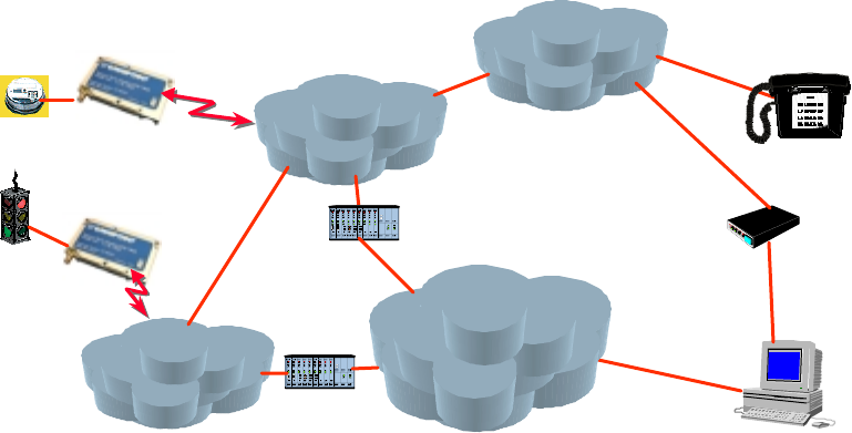
Incorporating GSM Communications into the Design
As shown in the Figure 1, the Eagle II module is designed for easy integration with other
components and packaging by leveraging the existing public GSM networks. Compare
the Eagle II to systems that require the construction, operation, maintenance, and
expense of a private wireless network.
Figure 1: Applications Using the Eagle II module in a GSM Network
The Eagle II module supports the following GSM features:
! Short Message Service (SMS)
! Unstructured Supplementary Service Data (USSD)
! Circuit Switched Data (Transparent and Non-Transparent modes) for transmitting and
receiving data
! Voice communications: Supports half-rate, full-rate and enhanced full-rate (EFR)
vocoding schemes.
The Eagle II module communicates via a V.24 serial interface and uses the GSM AT
command set. In addition, unique AT commands (see page 23) provide the opportunity to
monitor and report network conditions that may be relevant to the network management
of numerous deployed terminals.
GSM
Network
PSTN
User
MO DEM
Circuit Sw itched
Data Applica tions
Voice Applications
GSM
Network
Packet Data Applica tions
(Future)
IN TERN ET
Gatew ay
Gatew ay
SM S Applica tions
GPRS Applications
(Future)

Eagle II GSM Radio Module Technical Manual Preliminary Draft: 08/31/00 9
Part Number: 07100017 version 00.04
© 2000 Xircom, Inc. All rights reserved.
All trademarks and copyrights are the property of Xircom, Inc.
Summary of the Features for the Eagle II Radio Module
Data input/output interface 60-pin, dual-row connector: 0.8 mm pitch, surface mount
Primary serial port V.24 protocol, 3 V (5 V tolerant) levels
Secondary serial port Secondary 3 V serial port (Any functions other than SMS messaging
requires the development of custom applications)
Voice Supports three vocoder modes: half-rate, full-rate, and enhanced
full-rate (EFR)
Antenna Female SMA or female MCX versions available
Command protocol AT command set
Subscriber Identification Module
(SIM)
3 V mini-SIM carrier and interface on board
Interface
Optional remote SIM Accessible via the 60-pin connector
Electrical power Fixed DC voltage
Power
Peak currents and average power
dissipation
Refer to the Operating Power table in the Technical Specifications
for peak currents and average power dissipation for various modes
of operation.
Frequency bands GSM 900, DCS 1800, and PCS 1900 capability, depending on the
product.
Radio Features
GSM features supported Provides for all GSM authentication, encryption, and frequency
hopping algorithms.
Regulatory Agency approvals " GSM Type Approval
" FCC Certification (Part 24)
" CE (European Community Certification)
" IC (Industry Canada) available
GSM
Functionality
" Mobile-originated and mobile-terminated SMS messages: up to 140 bytes or up to 160 GSM 7-bit
ASCII characters. Up to 255 messages may be concatenated.
" Reception of Cell Broadcast Message
" SMS Receipt acknowledgement
" Circuit Switched Data (Transparent & Non-transparent programmable from 300 bps to 14.4 Kbps
" Voice
" Group 3 Fax
" Supports GSM Phase 2+
" Supports Unstructured Supplementary Service Data (USSD)
Not all GSM operators support USSD. For more information, contact Customer Support for the GSM
operator.
Eagle II hardware is capable of supporting General Packet Radio Services (GPRS) if configured with
optional memory. (GPRS Class B, Multislot Class 10 software will be available at a later date.)

Eagle II GSM Radio Module Technical Manual Preliminary Draft: 08/31/00 10
Part Number: 07100017 version 00.04
© 2000 Xircom, Inc. All rights reserved.
All trademarks and copyrights are the property of Xircom, Inc.
SIM 3 V Mini-Subscriber Identity Module (SIM) carrier and interface on board
International
Mobile
Equipment
Identity (IMEI)
The IMEI allows defective or stolen equipment to be barred from using the GSM network.
The IMEI number is unique to each Eagle II module. It reveals the manufacturer, the country of production,
and the type approval facility. When the Eagle II module is powered on and tries to register with the GSM
network, the network provider checks the IMEI. If the IMEI is valid and has not been barred, the Eagle II
module is allowed to register with the network.
Developer's Kit Eagle II Developer's Kit provides equipment for reducing the time required to develop an application that
utilizes the Eagle II module. For more information, refer to:
www.omnipoint-tech.com
TECHNICAL SPECIFICATIONS
Physical Dimensions and Weight
Size (L x W x H) 85.34 mm x 52.32 mm x 13.21 mm
(3.36” x 2.06” x 0.52”)
Weight 114 g (Less than 4 oz.)
Climatic: Operational
Operating temperature -20°C to +55°C
Note: Upper temperature range can be extended under
certain operating conditions. Consult application note
TBD.
Relative humidity 5 - 95%
Solar radiation Not Applicable
Air pressure (altitude) 70 kPa to 106 kPa (-400 m to 3000 m)
Climatic: Storage and Transportation
Duration 24 months
Ambient temperature -40°C to +85°C
Relative humidity 5% to 95%, non condensing (at 40°C)
Thermal shock -50°C to +23°C, +70°C to +23°C; < 5 min
Altitude -400 m to 15,000 m
Mechanical: Operational
Operational vibration, sinusoidal 3.0 mm disp, 2 to 9 Hz; 1 m/s2, 9 to 350 Hz

Eagle II GSM Radio Module Technical Manual Preliminary Draft: 08/31/00 11
Part Number: 07100017 version 00.04
© 2000 Xircom, Inc. All rights reserved.
All trademarks and copyrights are the property of Xircom, Inc.
Operational vibration, random 0.1 m2/s3, 2 to 200 Hz
Mechanical: Storage and Transportation
Transportation vibration, packaged ASTM D999
Drop, packaged ASTM D775 method A, 10 drops
Shock, un-packaged 150 m/s2, 11 ms, half-sine per IEC 68-2-27
Drop, un-packaged 4-inch drop per Bellcore GR-63-CORE
Mechanical: Proposed Standards
Transportation ETSI Standard ETS 300 019-1-2 Class 2.3 Transportation
Operational ETSI Standard ETS 300 019-1-3 Class 3.1 Operational
Storage ETSI Standard ETS 300 019-1-1 Class 1.2 Storage
Electromagnetic Emissions
Radiated spurious FCC part 24 / Part 15 Class \ B
GSM 11.10 Section 12.2
EN 55022 Class B
Electromagnetic Immunity (per ETSI ETS 300 342-1)
Radio Frequency (RF)
Electromagnetic Field
3 V/m 800 – 1000 MHz; 1 KHz 80%
EN 61000-4-3
Electrostatic discharge (ESD) Contact discharge to coupling planes: ±2 KV, ±4 KV
Air discharge to coupling planes: ±2 KV, ±4 KV, ±8 KV
RF common mode 3 V rms (Level 2) 150 KHz – 80 MHz
EN 61000-4-6

Eagle II GSM Radio Module Technical Manual Preliminary Draft: 08/31/00 12
Part Number: 07100017 version 00.04
© 2000 Xircom, Inc. All rights reserved.
All trademarks and copyrights are the property of Xircom, Inc.
Operating Power
The Eagle II module requires an input voltage of 4.2 VDC to 5.2 VDC. The input source
voltage ripple should be less than 20% of the average supply voltage peak-to-peak under
normal operating conditions.
Eagle II Module Average Current (Amps) Peak Current (Amps)
1 TX 1 RX 0.38 A 2.28 A
GSM
1 RX 0.11 A 0.18 A
1 TX 4 RX 0.41 A 2.28 A
GPRS Class 10
2 TX 3 RX 0.66 A 2.28 A
GSM 900
Sleep Mode <20 mA
1 TX 1 RX 0.31 A 1.68 A
GSM
1 RX 0.11 A 0.18 A
1 TX 4 RX 0.34 A 1.68 A
GPRS Class 10
2 TX 3 RX 0.51 A 1.68 A
DCS 1800
and
PCS 1900
Sleep Mode <20 mA
Transmit Power
Eagle II module Power Class Transmit Power
1900 MHz
1800 MHz
GSM Power Class 1 1-W conducted power maximum (30 dBm +/- 2 dB),
measured at the antenna port
900 MHz GSM Power Class 4 2-W conducted power maximum (33 dBm +/- 2 dB),
measured at the antenna port
Receiver Sensitivity
The receiver sensitivity measured at the antenna port is -106 dBm (minimum).
Eagle II GSM Radio Module Technical Manual Preliminary Draft: 08/31/00 13
Part Number: 07100017 version 00.04
© 2000 Xircom, Inc. All rights reserved.
All trademarks and copyrights are the property of Xircom, Inc.
Physical Layout for the Eagle II Module
Refer to the Eagle II Interface Control Drawing (ICD), Document # 06700103, for
information about the physical layout of the Eagle II module. The ICD provides the
following information:
! Physical dimensions and location of interfaces
! 60-pin I/O connector
♦ Connector location
♦ Pin locations
♦ Mating connector stack-up
! Antenna connector
♦ Options
♦ Location
♦ Torque specification
! SIM card
♦ Location
♦ Clearances for installation and removal
♦ Instructions for installation and removal
! Mounting features
♦ Recommended fastener sizes
♦ Fastener torque
♦ Printed circuit board (PCB) layout
! Location of the status LED

Eagle II GSM Radio Module Technical Manual Preliminary Draft: 08/31/00 14
Part Number: 07100017 version 00.04
© 2000 Xircom, Inc. All rights reserved.
All trademarks and copyrights are the property of Xircom, Inc.
PHYSICAL INTERFACES OF THE EAGLE II
MODULE
The Eagle II module provides the following interfaces:
! Antenna connector, which allows the Eagle II module to communicate with other
GSM devices.
! Signals on the 60-pin I/O connector allow the carrier board of the application to
communicate with the Eagle II module. Two V.24 serial data interfaces allow
simultaneously holding a circuit-switched call while sending and receiving SMS
messages
! LED indicator provides a visual indicator for the operational status of the module
Refer to the Eagle II Interface Control Drawing (ICD), Document # 06700103, for the
physical locations of these interfaces.
Note: For optimum performance and reliability, ensure that all mating connectors
have a minimum of .76 microns (30 micro-inches) of gold plating on contact
surfaces.
Antenna Interface
The Eagle II module is designed to support interchangeable antenna types, provided that
each antenna has 50-ohm impedance and has been tuned to the frequency band
intended.
The Eagle II module provides a connector for either a female SMA-type antenna
(standard) or a female MCX antenna (optional). This allows a choice in the type of
antenna configuration best suited for the application. The SMA-type connector is
recommended for high-vibration or mobile environments.
Input/Output (I/O) Signal Connector
The Eagle II module communicates with the carrier board via a 60-pin, dual-row, surface-
mount connector with a 0.8 mm pitch.

Eagle II GSM Radio Module Technical Manual Preliminary Draft: 08/31/00 15
Part Number: 07100017 version 00.04
© 2000 Xircom, Inc. All rights reserved.
All trademarks and copyrights are the property of Xircom, Inc.
Mating Connector on the Carrier Board of the Application
The carrier board must provide a mating 60-pin connector. The following table describes
the recommended connectors:
Vendor P/N
Description Manufacturer Tube Package Tape Package
60 pin female AMP (717) 564-0100 177983-2 177985-2
60 pin female Berg (800) 237-2374 61082-061000 61082-061002
Note: The nominal PCB-to-PCB connector stack height (provided by the Eagle II
module) is 8 mm (0.315 inches). If required, mating connectors with 12 mm and
16 mm stack heights are available from the listed manufacturers. When using
higher stack height connectors, the mating carrier board must provide standoffs to
accommodate the increased connector stack height.
I/O Signal Connector on the Eagle II Module
The Eagle II module communicates with the carrier board of the application via the 60-pin
I/O signal connector. The following table describes the pin assignments for the connector,
sorted by functionality.
I/O Connector Pin Assignments, Sorted by Functionality
Pin
Number
Signal
Name
Direction Functionality Voltage
Level
Power
1, 2, 3, 4, 5, 6 VIN From CPE Electrical power input to Eagle II module:
4.2 VDC to 5.2 VDC
Refer to the table for Operating Power.
21, 24, 25, 28, 29,
33, 44, 45, 48, 49,
52, 53, 57
GND From CPE Electrical power return for digital and analog grounds.
Reset/Primary Serial I/O
23 RESET_B From CPE Reset Input. Active Low. Internally pulled high and can be
left disconnected if not used. If connected to external
circuitry, maximum high level must not exceed 3.3 V.
Pulse width must be at least 5 mS to guarantee a valid
reset.
3 V *
8RX0 To CPE Receive data 0. DCE Output signal. Main serial interface
transmit data signal. During idle or reset, signal will be a
logic 1. Connects to a DTE, RX, receive data pin.
3 V

Eagle II GSM Radio Module Technical Manual Preliminary Draft: 08/31/00 16
Part Number: 07100017 version 00.04
© 2000 Xircom, Inc. All rights reserved.
All trademarks and copyrights are the property of Xircom, Inc.
Pin
Number
Signal
Name
Direction Functionality Voltage
Level
16 TX0 From CPE Transmit data 0. DCE Input signal. Active low. Main serial
interface receive data signal. During idle or reset, signal
will be a logic 1. Connects to a DTE, TX, transmit data
pin.
5 V or 3 V
18 CTS0 To CPE Clear-To-Send 0. DCE Output signal. Active low. Main
serial interface clear to send signal. Connects to a DTE,
CTS, Clear to send pin.
3 V
20 RTS0 From CPE Request-To-Send 0. DCE Input signal. Active low. Main
serial interface request to send signal. Connects to a
DTE, RTS, Request-To-Send pin.
5 V or 3 V
22 DTR0 From CPE Data Terminal Ready 0. DCE Input signal. Active low.
Main serial interface data terminal ready signal. Connects
to a DTE, DTR, Data Terminal Ready pin.
5 V or 3 V
10 DSR0 To CPE Data Set Ready 0. DCE Output signal. Active low. Main
serial interface data set ready signal. Connects to a DTE,
DSR, Data Set Ready pin.
3 V
12 DCD0 To CPE Data Carrier Detect 0. DCE Output signal. Active low.
Main serial interface data carrier detect signal. Connects
to a DTE, CD, Carrier Detect pin.
3 V
14 RI0 To CPE Ring Indicator 0. DCE Output signal. Active low. Main
serial interface ring indicator signal. Connects to a DTE,
RI, Ring Indicator pin.
3 V
Microphone
47 MIC1P From CPE Microphone 1 Positive. Positive input pin from an electret-
type microphone. Nominal microphone differential voltage
should be 2.0 volts. Impedance not less than 900 ohms.
Leave signal disconnected if function is not used.
51 MIC1N From CPE Microphone 1 Negative. Negative input pin from an
electret-type microphone. Nominal microphone differential
voltage should be 2.0 volts. Impedance not less than 900
ohms. Leave signal disconnected if function is not used.
Speaker
55 SPK1P To CPE Speaker 1 Positive. Positive output pin. High side of a
push-pull amplifier. Speaker impedance 15 ohms,
minimum. Speaker capacitance of 700 pF, maximum.
Driver voltage is 4.5 V peak-to-peak. Leave signal
disconnected if function is not used.
59 SPK1N To CPE Speaker 1 Negative. Negative output pin. Low side of a
push-pull amplifier. Speaker impedance 15 ohms,
minimum. Speaker capacitance of 700 pF, maximum.
Driver voltage is 4.5 V peak-to-peak. Leave signal
disconnected if function is not used.

Eagle II GSM Radio Module Technical Manual Preliminary Draft: 08/31/00 17
Part Number: 07100017 version 00.04
© 2000 Xircom, Inc. All rights reserved.
All trademarks and copyrights are the property of Xircom, Inc.
Pin
Number
Signal
Name
Direction Functionality Voltage
Level
Clock
27 CLKOUT To CPE Clock output. A 50% duty cycle 13 MHz square wave
clock source. Used for synchronization of external
circuitry to the base band processor. Leave signal
disconnected if function is not used.
3 V
General Purpose I/O
13, 15, 17, 19 GPIO0-GPIO3 To/From CPE General purpose I/O bits 0 through 3. Used as general
purpose input or output lines for monitoring or control of
external devices. Requires customized stack software to
implement. Leave signals disconnected if function is not
used.
3 V
LED Status Signals
40, 42 LED0-LED1 To CPE Status LED signal 0 and 1. Outputs are active low. LED0
corresponds to the “red” element of a bi-color LED. LED1
corresponds to the “green” element of a bi-color LED.
These signals indicate radio link status on a remote LED.
Leave signals disconnected if function is not used.
3 V
Transmit and Receive Data Lines
26 TX1 To CPE Transmit Data 1. DTE Output signal. Secondary serial-
interface transmit data signal. Used as a debug interface
for test purposes. Leave signal disconnected if function is
not used.
3 V
30 RX1 From CPE Receive Data 1. DTE Input signal. Secondary serial-
interface receive data signal. Used as a debug interface
for test purposes. Leave signal disconnected if function is
not used.
5 V or 3 V
SIM Signals (Data Power Control )
58 SIM-VCC To CPE SIM 3 volt power. A 3-volt power supply output signal to a
remote SIM device. Power is controlled by the base band
processor. Leave signal disconnected if function is not
used.
3 V or 5 V
56 SIM-IN From CPE SIM IN signal. Active high. A remote SIM card detection
signal input. Leave signal disconnected if function is not
used.
5 V or 3 V
54 SIM-RST To CPE SIM reset. An output signal to reset a remote SIM device.
Leave signal disconnected if function is not used.
3 V
50 SIM-IO To/From CPE SIM input output. Serial I/O line to a remote SIM device.
Leave signal disconnected if function is not used.
5 V or 3 V
46 SIM-CLK To CPE SIM clock output signal to a remote SIM device. Clock
frequency is 3.25 MHz. Leave signal disconnected if
function is not used.
3 V or 5V

Eagle II GSM Radio Module Technical Manual Preliminary Draft: 08/31/00 18
Part Number: 07100017 version 00.04
© 2000 Xircom, Inc. All rights reserved.
All trademarks and copyrights are the property of Xircom, Inc.
Pin
Number
Signal
Name
Direction Functionality Voltage
Level
60 SIM-3 V To CPE SIM 3 V output used in conjunction with the SIM-IN signal
to a remote SIM device. Leave signal disconnected if
function is not used.
3 V
Status
7TX on To CPE Transmit ON. Digital output to indicate transmitter power
status. A logic 1 indicates transmit power is on. A logic 0
indicates transmit power is off. Leave signal disconnected
if function is not used.
2.2 V
9RX on To CPE Receive ON. Digital output to indicate receiver power
status. A logic 1 indicates receiver power is off. A logic 0
indicates receive power is off. Leave signal disconnected
if function is not used.
2.2 V
Reserved: Do Not Use
11, 31, 32, 34,35,
36, 37, 38, 39, 41,
43
Reserved Leave open: do not use.
Subscriber Identification Module (SIM) Carrier
The Eagle II module uses a push/pull SIM carrier (sometimes called SIM reader) and is
installed as a slot on the side of the module. The Eagle II module uses a 3 V removable
“mini-SIM” (or Plug-In) configuration.
The SIM, an integral part of any GSM terminal device, is a “smart card” that is
programmed with subscriber information:
! The user information consists of an International Mobile Subscriber Identity (IMSI)
number, which is registered with the GSM provider, and an encryption Ki
(pronounced "key"). This information consists of a microprocessor and memory
installed on a plastic card.
Note: The SIM is not provided with the Eagle II module. The SIM must be obtained
from the GSM service provider and must be provisioned by the operator for data
and/or voice. Always take care to protect the SIM: the GSM terminal will not operate
without the SIM installed.
The SIM provides the IMSI for authentication. To gain access to the GSM network, the
network must recognize the IMSI number, and the terminal must be able to properly
decrypt the data sent by the network. The SIM also serves as a buffer for SMS
messages, storing the message for transmission until a radio link is available and
buffering received messages until retrieved.
Using a Remote SIM with the Eagle II Module
The Eagle II module also allows the use of a remote SIM—one not installed in the
Eagle II module.
! To utilize a remote SIM, the integrator must provide a suitable SIM connector on the
application

Eagle II GSM Radio Module Technical Manual Preliminary Draft: 08/31/00 19
Part Number: 07100017 version 00.04
© 2000 Xircom, Inc. All rights reserved.
All trademarks and copyrights are the property of Xircom, Inc.
! The maximum distance from the Eagle II to the remote SIM connector must not
exceed TBD cm (TBD inches).
Status Indicator
The Eagle II module provides a multi-color LED that indicates the current link status and
signal quality.
Note: The LED illuminates any time power is applied to the Eagle II module.
LED Color Link Status Signal Quality
Green Link signal is optimal
Orange Link is less than optimal but is acceptable
Solid Red
Module is attached
to the network
Link is unacceptable
Flashing Red Module is in Start-up mode or is not attached to the network

Eagle II GSM Radio Module Technical Manual Preliminary Draft: 08/31/00 20
Part Number: 07100017 version 00.04
© 2000 Xircom, Inc. All rights reserved.
All trademarks and copyrights are the property of Xircom, Inc.
MODES OF OPERATION
GSM supports many optional services and modes. The Eagle II module supports the
following GSM services:
! Voice communication
! Circuit-switched data
! Short-Message Services (SMS)
! Group 3 Fax
! General Packet Radio Service (GPRS)
Enabling the Transmission Modes for the GSM Services
Each of the GSM services has two modes that can be enabled separately:
! Mobile-originated (MO): allows the making of a service request (such as, making a
telephone call or sending an SMS)
! Mobile-terminated (MT): allows receiving a service request (such as receiving a
telephone call or an SMS)
Note: Contact your local GSM operator to ensure that the services and modes have
been provisioned for the SIM.
Voice Communication
The Eagle II module has full voice capabilities, provided the necessary connections have
been made for the speaker and microphone pins on the 60-pin I/O connector. The AT
commands and their responses to enter and receive information from the Eagle II
module. These functions include the ability for dialing, for providing on-hook or off-hook,
and for controlling other aspects of the voice call interface.
The Eagle II module supports three vocoder compression algorithms for voice
communication: half-rate, full-rate, and enhanced full-rate (EFR)
Circuit-Switched Data
In this mode, the Eagle II module supports both of the connection modes of transmission
that are provided by GSM:
! Transparent data mode delivers a service with a variable error rate, with a
guaranteed throughput and delay.
! Non-Transparent mode delivers a constantly low error rate but with a non-guaranteed
throughput or delay. The Non-Transparent service provides a performance that is
closest to using a modem over a fixed Public Switched Telephone Network (PSTN)
line.
Note: All GSM service providers may not support Transparent mode. In those
cases, the Eagle II module switches automatically to Non-Transparent mode.
Eagle II GSM Radio Module Technical Manual Preliminary Draft: 08/31/00 21
Part Number: 07100017 version 00.04
© 2000 Xircom, Inc. All rights reserved.
All trademarks and copyrights are the property of Xircom, Inc.
SMS: Short Message Services
Short Message Services (SMS) is a feature-rich GSM service. The Eagle II module can
perform the following tasks:
! Sending and receiving text messages of up to 160 characters (7-bit characters)
! Sending and receiving binary messages of up to 140 bytes (8-bit data)
! Submitting a SMS Protocol Data Unit (PDU) to a SMSC (Short Message Service
Center) and storing a copy of the PDU until either a report arrives from the network or
a timer expires
! Receiving a SMS PDU from a SMSC
! Returning a delivery report to the network for a previously received message
! Receiving a report from the network
! Notifying the network when the module has sufficient memory capacity available to
receive one or more SMS messages (after the module had previously rejected a
message because its memory capacity was exceeded)
SMS Features Supported by the Eagle II Module
The following list details the key characteristics and assumptions regarding the form of
SMS supported in the Eagle II module.
! Supports both mobile-originated (MO) and mobile-terminated (MT) SMS
! Delivers the message to a telephone
! Supports 8-bit data
! Supports Message Class 1
! Supports the concatenation of up to 255 messages
! Provides a status report indicator
! Supports the More Messages to Send (MMS) feature
! Allows the definition of a validity period
! Provides the Service Center Time Stamp
! Alerts the SMSC
! Supports Priority
! Supports Message Waiting
! GPRS (Future/Optional)
General Packet Radio Service (GPRS)
GPRS is the next step in GSM data services: a fully packet-based protocol service with
direct access to the Internet. By bringing the best features of messaging, circuit-switched
services, and packet data into harmony, GPRS promises to make new applications even
more practical and affordable. Future releases of the Eagle II module will support GPRS
mode. Currently, the Eagle II module is hardware-ready for GPRS, if the optional memory
upgrade is installed.

Eagle II GSM Radio Module Technical Manual Preliminary Draft: 08/31/00 22
Part Number: 07100017 version 00.04
© 2000 Xircom, Inc. All rights reserved.
All trademarks and copyrights are the property of Xircom, Inc.
PROVISIONING THE SIM
The GSM SIM can support optional features or services. Most GSM operators typically
configure the SIM to send/receive voice calls and to receive SMS; however, some may
require an additional tariff to enable the SIM to send SMS. The transmission of data and
fax are also additional services that may require tariffs and additional provisioning. Each
of these services has two separate modes that must be enabled to allow the service:
! Mobile-originated (MO): allows making a service request (such as, making a call or
sending an SMS)
! Mobile-terminated (MT). allows receiving a service request (such as, receiving a
phone call or an SMS)
It is imperative for the Eagle II module that the SIM be configured for the optional
services that are required for the application.
GSM Services Supported by the Eagle II Module
The Eagle II module supports four GSM services (modes of operation) that must be
enabled by the operator:
! Voice calls (MO and MT): requires a telephone number
! SMS (MO and MT): uses the telephone number for Voice
! Fax calls (MO and MT): requires a telephone number
! Circuit-switched data calls (MO and MT): requires a telephone number
The GSM SIM can have as many as three telephone numbers: one number for voice
calls and SMS, one number for fax calls, and one number for data calls.
Selecting the Modes of Operation
When provisioning the SIM for the Eagle II module, enable the following modes of
operation:
! Voice calls: configure the SIM for both MO and MT service (to send and receive)
! SMS: configure the SIM either for MT alone (to receive) or for both MO and MT (to
send and receive)
! Data: configure the SIM either for MO alone (to send) or for both MO and MT (to
send and receive)
Voice SMS Data Fax Function
MO/MT MT MO XVoice calls, receive SMS, make data calls
MO/MT MT/MO MO XVoice calls, receive/send SMS, make data calls
MO/MT MT/MO MO/MT XVoice calls, receive/send SMS, make/receive data calls
(requires an additional data telephone number)

Eagle II GSM Radio Module Technical Manual Preliminary Draft: 08/31/00 23
Part Number: 07100017 version 00.04
© 2000 Xircom, Inc. All rights reserved.
All trademarks and copyrights are the property of Xircom, Inc.
SOFTWARE INTERFACE OF THE EAGLE II
MODULE
The application sends commands to the Eagle II module via the 60-pin I/O signal
connector. These commands use the AT (from "AT-tention") command set.
The Eagle II module operates in one of the following modes:
! Command mode: Used for configuring the Eagle II module, for interrogating the GSM
network, and for placing and receiving calls. It uses the AT command set via the
serial port for communication.
! On-line mode: Used after a circuit-switched data call has been established. Data is
passed between the Eagle II module and the controlling application without
command interpretation. The only AT command that is interpreted in On-line mode is
the +++ command. (This command places the Eagle II module in Command mode
but does not terminate the circuit-switched data call.)
The AT command driver of the Eagle II module never exits the Command state, that is, it
never enters the On-line mode.
! In the Command state, characters that are received from the Customer Premise
Equipment (CPE) are treated as AT commands by the Eagle II module.
! In response to the commands received from the CPE, the Eagle II module sends
characters (AT commands) to the CPE.
! Various events can also trigger the Eagle II module to sends characters (AT
commands) to the CPE.
Format for the AT Commands
The general format of the command line is: <prefix> <command> <CR>
The prefix AT obtains synchronization, identifies the character parameters, and indicates
that a command may be in the following characters.
AT commands are not case sensitive: use either capital letters or lower-case letters for
the AT command.
AT Command Set
The following tables summarize the functional categories of AT commands that are
supported by the Eagle II module. For a full description of the AT commands, refer to the
Eagle II Programmer's Manual.
Note: A command description that includes an *asterisk denotes that the GSM
service provider must enable supplementary services functionality before the
command is available.

Eagle II GSM Radio Module Technical Manual Preliminary Draft: 08/31/00 24
Part Number: 07100017 version 00.04
© 2000 Xircom, Inc. All rights reserved.
All trademarks and copyrights are the property of Xircom, Inc.
Call Control Commands
Command Description
+++ Escape to Command mode
A/ Repeat last command
AT Attention (prefix to all AT commands)
ATA Answer a call
ATD Dial a call
ATH Hang up a call
ATO Return to On-line mode
ATQ Result Code suppression
ATV Result Code format
ATX Call Progress monitoring
AT+CBST Bearer service selection
AT+CHUP Hang up a call
AT+CR Service report configuration
AT+CRC Set the cellular result codes
AT+CRLP Radio Link protocol
AT+FCLASS Select the Call mode
GSM Network Commands
Command Description
AT+CNUM Subscriber services
AT+COPS Operator selection
AT+CREG Network registration information
AT+CSQ Read the signal strength
GSM Terminal Commands
Command Description
ATI Read the equipment information
ATZ Reload the manufacturer’s default values

Eagle II GSM Radio Module Technical Manual Preliminary Draft: 08/31/00 25
Part Number: 07100017 version 00.04
© 2000 Xircom, Inc. All rights reserved.
All trademarks and copyrights are the property of Xircom, Inc.
Command Description
AT+CGMI Read the manufacturer’s name
AT+CGMM Read the model code for the equipment
AT+CGMR Read the revision for the equipment
AT+CGSN Read the serial number
AT+CLCK * Facility lock
AT+CMEE Control Error reporting
AT+CPAS Phone activity status
AT+CPIN Enter the Personal Identity Number (PIN)
AT+CPWROFF Power-off the GSM terminal
AT+CSCS Select the GSM terminal character set
AT+GCAP Read the GSM terminal capabilities
AT+GMI Read the manufacturer’s name
AT+GMM Read the equipment model code
AT+GMR Read the equipment revision number
AT+GSN Read the serial number
AT+ICF Read the control character framing
AT+IFC Set the TE-TA Local Data Flow control
AT+IPR Set the serial data rate
AT&C Set to Data Carrier Detect (DCD) mode
AT&D Set to Data Terminal Ready (DTR) mode
AT&F Set to the Configuration Profile
AT&H Request the Help screen
AT&V View the current configuration
AT&W Save the current configuration

Eagle II GSM Radio Module Technical Manual Preliminary Draft: 08/31/00 26
Part Number: 07100017 version 00.04
© 2000 Xircom, Inc. All rights reserved.
All trademarks and copyrights are the property of Xircom, Inc.
AT Commands for SMS
Command Description
AT+CMGD Delete message from memory
AT+CMGF Control Message mode
AT+CMGL List messages
AT+CMGR Read message
AT+CMGS Send message
AT+CMGW Write message to memory
AT+CMSS Send message from storage
AT+CNMI Set new SMS message indications
AT+CPMS Configure the message storage
AT+CRES Restore the SMS settings
AT+CSAS Save the SMS settings
AT+CSCA Set the address for the SMS service center
AT+CSDH Show the Text mode parameters
AT+CSMP Set the Text mode parameters
AT+CSMS Select message service
S Registers
Command Description
ATS0 Sets the number of rings before automatically answering the call
ATS3 Sets the Command Line Termination character
ATS4 Sets the Response Formatting character
ATS5 Sets the Command Line Editing character
ATS6 Sets the number of seconds to wait before dialing a call
ATS7 Sets the number of seconds to wait for completion of call answering or originating
ATS8 Sets the number of seconds to wait when a comma dial modifier is encountered in
the dial string of an ATD command
ATS10 Sets the number of tenths of seconds to wait before disconnecting the call
following the absence of received line signal

Eagle II GSM Radio Module Technical Manual Preliminary Draft: 08/31/00 27
Part Number: 07100017 version 00.04
© 2000 Xircom, Inc. All rights reserved.
All trademarks and copyrights are the property of Xircom, Inc.
Result Codes
Command Description
BUSY Final Result Code: Busy signal detected
CONNECT Intermediate Result Code: Connection has been established
CONNECT <text> Intermediate Result Code: Connect with manufacturer-specific text
ERROR Final Result Code: Command not accepted
NO ANSWER Final Result Code: Connection completion timeout
NO CARRIER Final Result Code: Connection terminated
NO DIAL TONE Final Result Code: Connection terminated
OK Final Result Code: Acknowledges execution of a command line
RING Unsolicited Result Code: Incoming call signal from network

Eagle II GSM Radio Module Technical Manual Preliminary Draft: 08/31/00 28
Part Number: 07100017 version 00.04
© 2000 Xircom, Inc. All rights reserved.
All trademarks and copyrights are the property of Xircom, Inc.
INITIALIZATION AND SETUP EXAMPLES
In the GSM vocabulary, a call from GSM mobile to the PSTN is called a "mobile-
originated call" or "outgoing call." A call from the fixed network to a GSM mobile is called
a "mobile-terminated call" or "incoming call."
In the following examples, “App” refers to the application. The following convention
describes the direction of the data exchange:
! The data exchange from the customer application to the Eagle II module is
designated as: App > Eagle
! The data exchange from the Eagle II module to the customer application is
designated as: Eagle> App
Note: With the exception of the +++ command (Online Escape Sequence), all
commands must be preceded by the AT attention code (or command prefix) and
terminated by pressing the <CR> character.
In the following examples, the <CR> and <CR><LF> are intentionally omitted for
clarity and space.
Initial Response to the AT Command
After power is applied to the Eagle II module, the module performs a power-up self-test.
The self-test completes within TBD seconds. When queried with the AT command, the
Eagle II module responds with one of the following result codes:
! OK signifies that the Eagle II module is ready, that it correctly interprets the AT
command, and that it can execute the command.
! ERROR signifies that the Eagle II module does not understand the command or that
the command is invalid.
App > Eagle AT
Eagle > App OK Command valid: module is ready
The Eagle II module must be in Command mode when any command is entered (with the
exception of the online escape sequence +++). Commands entered when the module is
in Online mode are treated as data, and are transmitted as such to the receiving module.

Eagle II GSM Radio Module Technical Manual Preliminary Draft: 08/31/00 29
Part Number: 07100017 version 00.04
© 2000 Xircom, Inc. All rights reserved.
All trademarks and copyrights are the property of Xircom, Inc.
Sending an Initialization String to the Eagle II Module
The following example provides the sample AT commands and responses for the
following initialization tasks:
! Reset the module to the factory defaults
! Enable character echo
! Set the module to Verbose mode (to display result codes as words)
! Set the DCD to ON
! Monitor the DTR
App > Eagle AT& FE0Q0V1&C1&D2 Initialization string
Eagle > App OK Command is valid
App > Eagle ATSO=1 Auto answer on 1st ring
Eagle > App OK Command is valid
Setting Up the Communication Mode for the Eagle II Module
The following example provides the AT command and response for setting the Eagle II
module for 9600 baud, non-transparent mode.
App > Eagle AT+CBST=7,0,1 9600 baud, non-transparent mode
Eagle > App OK Command is valid
Querying the Status of the Eagle II Module
The following examples provide the AT commands and responses for querying the status
of the unit. For more information about the commands and response codes, see the
Eagle II Programmer's Manual.
! The following command checks to determine if the Eagle II module has successfully
registered with the GSM network.
App > Eagle AT+CREG? Get the registration status
Eagle > App +CREG: 0,1
OK
Registered with home network
+CREG=0,2 registration in progress
+CREG=0,5 registered as roaming

Eagle II GSM Radio Module Technical Manual Preliminary Draft: 08/31/00 30
Part Number: 07100017 version 00.04
© 2000 Xircom, Inc. All rights reserved.
All trademarks and copyrights are the property of Xircom, Inc.
! The following command queries the strength of the RF coverage. This command
provides information about the RF coverage for the Eagle II module.
App > Eagle AT+CSQ Get the signal strength (for this command, do not
enter “?”)
Eagle > App +CSQ: 10,99
OK
Receive signal strength = 10, -95 dBm
RXQUAL =99, unknown
! The following command requests the current Public Land Mobile Network (PLMN).
App > Eagle AT+COPS? Request current PLMN
Eagle > App +COPS: 0,2,31026
OK
Home PLMN is VoiceStream
Initialize the EAGLE II Module to Send SMS Text
To be able to send SMS text messages, the Eagle II module must be initialized with the
proper SMS mode. The following examples provide the AT commands and responses for
initializing the SMS mode.
! The following command initializes the Eagle II module by setting the text mode
parameters.
App > Eagle AT+CSMP=17,167,0,0 Set text mode parameters:
" 17: Sets reply pat, user data header,
status report request, validity period
format, reject duplicates and
message type
" 167: Sets validity period
" 0: Higher layer protocol indicator
" 0: Information encode format
Eagle > App OK Command is correct

Eagle II GSM Radio Module Technical Manual Preliminary Draft: 08/31/00 31
Part Number: 07100017 version 00.04
© 2000 Xircom, Inc. All rights reserved.
All trademarks and copyrights are the property of Xircom, Inc.
! After initializing the module with the proper SMS mode, select the proper service
center. The service center is the Public Land Mobile Network (PLMN) to which the
SME telephone number belongs. The following command selects the service center.
App > Eagle AT+CSCA="1917907004" Service center initialization:
VoiceStream SMSC – NJ
Eagle > App OK
! The following command selects TEXT mode for SMS messages.
App > Eagle AT+CMGF=1 Set message format to TEXT mode
Eagle > App OK Command is correct
! The following command sets the indicators for the message.
App > Eagle AT+CNMI=0,1,0,0,0 Set the new message indicators
AT+CNMI=<mode>,<mt>,<bm>,<ds>,<bfr>
" <mode>=0, Buffer unsolicited result codes
indication
" <mt>=1, SMS-DELIVERs are routed using
unsolicited code
" <bm>=0, no CBM indications are routed
to the TE
" <ds>=0, no SMS-STATUS-REPORTs
" are routed
" <bfr>=0, TA buffer of unsolicited result
codes defined within this command is
flushed to the TE
Eagle > App OK Successful command
! The following command saves the SMS settings. Once the SMS commands have
been saved, the initialization commands do not need to be sent again until they are
changed.
App > Eagle AT+CSAS Save SMS settings
Eagle > App OK Successful transmission
! After the Eagle II module has been initialized, the following commands and sample
responses provide the telephone number and the message to be transmitted.

Eagle II GSM Radio Module Technical Manual Preliminary Draft: 08/31/00 32
Part Number: 07100017 version 00.04
© 2000 Xircom, Inc. All rights reserved.
All trademarks and copyrights are the property of Xircom, Inc.
App > Eagle AT+CMGS="12017572673" Send a message to the telephone
number
Eagle > App >Ready to send message
App > Eagle Hello, how are you?^Z Enter the text message. End the
message with Control Z.
Eagle > App OK Successful transmission
Requesting to Receive the SMS Text
The following example provides the AT command for requesting that the Eagle II module
receive SMS messages. This string requests that the module send all of the messages
that have been received.
App > Eagle AT+CMGL=”ALL” Read ALL messages received, including status,
originator, message number and message content
Eagle > App +CMGL: 1, "REC UNREAD", "43322449"<CR>
To be, or not to be!
+CMGL: 3, "REC UNREAD", "46290800"<CR>
Hello Test Message!
OK

Eagle II GSM Radio Module Technical Manual Preliminary Draft: 08/31/00 33
Part Number: 07100017 version 00.04
© 2000 Xircom, Inc. All rights reserved.
All trademarks and copyrights are the property of Xircom, Inc.
Initiating a Data Call
The default traffic channel type for the Eagle II module is for data. The following example
provides the AT command for requesting the Eagle II module to initiate a data call.
App > Eagle AT + FCLASS = 0 Sets the traffic channel type to Data mode if the traffic
channel was previously changed to Voice mode.
(Data mode is the default traffic channel type.) Not
required if in the default mode
Note: This command is required only if the traffic
channel type has been changed from data mode
(default) to voice mode
Eagle > App OK
App > Eagle AT + CBST = 7,0,1 Sets the Bearer type to: 9600 Baud, non-Transparent
call
Eagle >App OK
App > Eagle ATD “1234567890” AT command to dial the phone number
Eagle > App OK
CONNECT 9600
The OK response is followed by the “Connect 9600”
response when the connection is completed.
App > Eagle ATH Terminates the call
Eagle > App OK
Eagle II GSM Radio Module Technical Manual Preliminary Draft: 08/31/00 34
Part Number: 07100017 version 00.04
© 2000 Xircom, Inc. All rights reserved.
All trademarks and copyrights are the property of Xircom, Inc.
Initiating a Voice Call
The Eagle II module supports the AT commands for requesting to initiate both mobile-
originated (MO) and mobile-terminated (MT) voice calls.
Mobile-Originated Call
The following example provides the AT command for requesting the Eagle II module to
initiate a mobile-originated (MO) voice call.
This command assumes that the Eagle II module is configured for the Data Call
mode (default).
App > Eagle AT + FCLASS = 8 Sets the traffic channel type to Voice mode
Eagle > App OK
App > Eagle ATD “1234567890” AT command to dial the telephone number
Eagle > App OK
App > Eagle ATH Terminates the call
Eagle > App OK
Mobile-Terminated Call
The following example provides the AT command for requesting the Eagle II module to
initiate a mobile-terminated (MT) voice call.
This command assumes the Eagle II is configured for the Data Call mode (default).
App > Eagle AT + FCLASS = 8 Sets the traffic channel type to voice.
Eagle > App OK
Ring Displayed for incoming call notification
App > Eagle ATA Command to manually answer the MT call. If “Auto
Answer” is required, the ATS0=x command, where x
= “the number of rings” is used.
Eagle > App OK
App > Eagle ATH Terminates the call
Eagle > App OK

Eagle II GSM Radio Module Technical Manual Preliminary Draft: 08/31/00 35
Part Number: 07100017 version 00.04
© 2000 Xircom, Inc. All rights reserved.
All trademarks and copyrights are the property of Xircom, Inc.
INTEGRATION AND TEST
The Eagle II module has been designed to minimize the amount of time required for
integrating and testing the application. By being fully GSM Type Approved, the Eagle II
module provides seamless integration into the GSM network.
The integration issues for the application can be narrowed to the utilization of the AT
commands and the use of the GSM functionality. Coverage and signal quality may be
evaluated by using the LED of the on-board status indicator. Additional network
information can be determined by using AT commands.
Using the Eagle II Developer's Kit to Reduce Development Time and Effort
The Eagle II Developer’s Kit can also speed the development and implementation of an
application. This kit provides a platform for the development of an embedded application
and can easily be tailored for custom applications. The kit also provides a significant
amount of pre-developed software intended to speed the development of the application
and to reduce the time required for bringing a new device to market.
For more information on the Eagle II Developer's Kit, refer to the Xircom, Inc. web site on
the Internet: www.omnipoint-tech.com
Integrating the Eagle II Module
Note: Generally, all interfaces that are externally available to the end user need to
be ESD-conditioned and terminated in some way. Many of these interfaces should
not be connected with power applied.
At the highest level, this is done using some type of GSM test equipment (such as, Racal
6103E), a computer, and a serial interface tester. The GSM test equipment must be able
to simulate a GSM call and measure the key parameters related to the module.
Additionally, the serial interfaces and some minimal SIM functionality can be verified by
sending AT commands to the Eagle II module.
All of this needs to be verified at ambient as well as extreme conditions.

Eagle II GSM Radio Module Technical Manual Preliminary Draft: 08/31/00 36
Part Number: 07100017 version 00.04
© 2000 Xircom, Inc. All rights reserved.
All trademarks and copyrights are the property of Xircom, Inc.
As part of integration, each of the following interfaces should be verified:
Interface Recommendations
SIM The maximum line length of the SIM interface is TBD cm (TBD inches).
The Eagle II module takes care of the signal conditioning
As a minimum, an external application with a remote SIM will require a
standard SIM carrier.
" Tie the SW1 signal of this to the SIM 3 V line via a 20k resistor.
" Filter the SIM VCC signal with a 10 uf / 10 V capacitor to help with the
line length.
Primary and
secondary serial
interfaces
The Eagle II module uses a 3 V digital interface that is 5 V tolerant.
The RS-232 signals must be level-shifted to get standard levels. These
signals must be ESD-protected.
Reset Interface Resets the Eagle II module when tied low.
Audio/Microphone
Interface
Preliminary balancing on Eagle II module.
Maximum length TBD
Testing the following parameters verifies the RF parameters that may be affected by such
things as RF path loss, power supply noise, and external interference.
Functionality Parameters to be Tested
Transmitter Frequency Error
Phase Error
PA Ramp
Modulation Spectrum
RF Power Steps
Timing Advance
Receiver BER Based RX Tests (RXQUAL RXLEV)
BER Based Sensitivity
Testing the following GSM functionality verifies proper network communication.
Functionality Parameters to be Tested
Network Function Synchronization and registration
Call set-up and call termination (both MT and MO calls)
SMS and/or data calls

Eagle II GSM Radio Module Technical Manual Preliminary Draft: 08/31/00 37
Part Number: 07100017 version 00.04
© 2000 Xircom, Inc. All rights reserved.
All trademarks and copyrights are the property of Xircom, Inc.
REPAIR AND RETURN POLICY
Note: The standard warranty for the Eagle II module is 90 days.
To report a problem, call the Xircom Customer Service department:
• United States of America (toll-free): 1.888.684.5355
• International: +1.719.884.2444
Reporting and Troubleshooting Problems with the Eagle II Module
Problems can be reported by calling Customer Service. The Customer Service
representative and/or service technician will attempt to resolve the problem over the
telephone. It is important to note the exact environment that the problem occurs and what
is the integration platform. For example, does the problem occur only in the Eagle test
fixture or in the target platform?
If the problem cannot be resolved over the telephone and the module needs to be
returned, the customer service representative provides an RMA number for shipping the
module. The return address will be given at this time.
Upon receipt of the module, it will be thoroughly tested in an Xircom test fixture. If the
problem is found, a replacement module will be shipped back to the customer.
Note: The warranty period for replaced or repaired equipment is 30 days from time
of shipment.

Eagle II GSM Radio Module Technical Manual Preliminary Draft: 08/31/00 38
Part Number: 07100017 version 00.04
© 2000 Xircom, Inc. All rights reserved.
All trademarks and copyrights are the property of Xircom, Inc.
REGULATIONS AND COMPLIANCE
This section summarizes the responsibilities and actions required of manufacturers and
integrators who incorporate OEM versions of the Eagle II module into their products. In
certain situations and applications these products will require additional FCC, CE, GSM
FTA or other regulatory approvals prior to sale or operation. Appropriate instructions,
documentation and labels are required for all products. For more information concerning
regulatory requirements, please contact Xircom, Inc.
GSM Full Type Approval (FTA)
The Eagle II module is type approved in accordance with the requirements of and
through the procedures set forth by the GSM industry association. The relevant
conformance specification is GSM 11.10-1 version 4.19.1 for GSM 900- and 1800 MHz
devices. For PCS 1900 MHz devices, the relevant standard is PCS 11.10, a version of
GSM 11.10-1 that has been modified as appropriate for the North American GSM market.
For applications that use an unmodified version of the Eagle II module, further testing in
this area may not be required. Any OEM changes in the SIM interface, antenna port,
software or the physical makeup of the unit may require an incremental FTA to ensure
continued compliance with the above-mentioned standards. For more information
concerning type approval, please contact Xircom, Inc.
Electromagnetic Compatibility (EMC) and Safety
Requirements
The Eagle II module has been tested and approved for application in the United States of
America (US) and the European Union (EU). The compliance details for each of these
markets follow. For other markets, additional or alternative regulatory approvals may be
required. Always ensure that all rules and regulations are complied with in every country
that the OEM application is to be operated. Regardless of the country or market, the
OEM must comply with all applicable regulatory requirements.
EMC/Safety Requirements for the USA
Compliance to the US rules and regulations falls under two categories:
! Radio approvals: Federal Communications Commission (FCC)
♦ Transmitter: FCC Rules, Part 24
♦ Unintentional emission: FCC Rules, Part 15
! Product safety approvals: NRTL by an OSHA-approved Nationally Recognized
Testing Laboratory (NRTL)
Although the Eagle II module has been authorized by the FCC and listed as a component
by an NRTL, products and applications that incorporate the Eagle II module will require
final verification of EM emission and product safety approval.
Note: Particular attention should be made to the following statements regarding RF
Exposure:

Eagle II GSM Radio Module Technical Manual Preliminary Draft: 08/31/00 39
Part Number: 07100017 version 00.04
© 2000 Xircom, Inc. All rights reserved.
All trademarks and copyrights are the property of Xircom, Inc.
Human Exposure Compliance Statement
Xircom, Inc. Wireless Technology Group certifies that the Eagle ™II 900/1900 MHz GSM
Radio Module (FCC ID: J3OEAG2919) complies with the RF hazard requirements
applicable to broadband PCS equipment operating under the authority of 47 CFR Part
24, Subpart E of the FCC Rules and Regulations. This certification is contingent upon
installation, operation and use of the Eagle ™ II and its host product in accordance with
all instructions provided to both the OEM and end used. When installed and operated in
a manner consistent with the instructions provided, the Eagle ™ II meets the maximum
permissible exposure (MPE) limits for general population / uncontrolled wxposure at
defined in Section 1.1310 of the FCC Rules and Regulations.
Note: Installation and operation of this equipment must comply with all applicable
FCC Rules and Regulations, including those that implement the National
Environmental Policy Act of 1969 (Part 1, Subpart I), with specific regard to antenna
siting and human exposure to radio frequency radiation. For further guidance,
consult the FCC Rules, your service provider, or Xircom Inc.
Compliance with FCC Regulations
The Federal Communications Commission (FCC) is the agency of the Federal
Government that oversees all non-governmental radio frequency transmitters that
operate within the United States. Unintentional emissions from digital devices are
regulated by Part 15 of the FCC Rules and Regulations, which distinguishes between the
environments in which these devices may operate. Intentional radiators operating as a
PCS-1900 radio transmitter are regulated under Part 24, Subpart E—Broadband PCS of
the FCC Rules and Regulations.
Eagle II GSM Radio Module Technical Manual Preliminary Draft: 08/31/00 40
Part Number: 07100017 version 00.04
© 2000 Xircom, Inc. All rights reserved.
All trademarks and copyrights are the property of Xircom, Inc.
Unintentional Radiators, Part 15
Equipment designated as Class A is intended for use in a commercial, industrial or
business environment. The Eagle II module has been tested and found to comply with
the limits for a Class A digital device and can be integrated into equipment or applications
intended for use in commercial, industrial or business environments.
The following statement must be included in the user manual for such products:
This equipment has been tested and found to comply with the limits for a Class A
digital device, pursuant to part 15 of the FCC rules. These limits are designed to
provide reasonable protection against harmful interference when the equipment is
operated in a commercial environment. This equipment generates, uses, and can
radiate radio frequency energy and, if not installed and used in accordance with the
instruction manual, may cause harmful interference to radio communications.
Operation of this equipment in a residential area is likely to cause harmful
interference in which case the user will be required to correct the interference at his
own expense.
Equipment intended for use in a residential environment (not-withstanding use in
commercial, industrial or business environments) is designated as Class B. The Eagle II
module has been tested and found to comply with the limits for a Class B digital device
and can be integrated into equipment or applications intended for use in residential
environments.
The following statement must be included in the user manual for such products:
This equipment has been tested and found to comply with the limits for a Class B
digital device, pursuant to part 15 of the FCC rules. These limits are designed to
provide reasonable protection against harmful interference in a residential
installation. This equipment generates, uses, and can radiate radio frequency energy
and, if not installed and used in accordance with the instructions, may cause harmful
interference to radio communications. However, there is no guarantee that
interference will not occur in a particular installation. If this equipment does cause
harmful interference to radio or television reception, which can be determined by
turning the equipment off and on the user is encouraged to try to correct the
interference by one or more of the following measures:
♦ Reorient or relocate the receiving antenna.
♦ Increase the separation between the equipment and receiver.
♦ Connect the equipment into an outlet on a circuit different from that to which the
receiver is connected.
♦ Consult the dealer or an experienced radio/TV technician for help.
Intentional Radiators, Part 24
Products incorporating the Eagle II transceiver operate as Personal Communications
Services (PCS) devices under the authority of Part 24, Subpart E—Broadband PCS, of
the FCC Rules and Regulations. All such transmitters must be authorized by the FCC
through its Certification process, as detailed in Part 2, Subpart J - Equipment
Authorization Procedures. Through the Certification process, the FCC verifies that the
product complies with all applicable regulatory and technical requirements, including
those that address human exposure to radio frequency radiation. In general, radio
frequency transmitters cannot be sold or operated in the US prior to FCC approval.

Eagle II GSM Radio Module Technical Manual Preliminary Draft: 08/31/00 41
Part Number: 07100017 version 00.04
© 2000 Xircom, Inc. All rights reserved.
All trademarks and copyrights are the property of Xircom, Inc.
Instructions to the Original Equipment Manufacturer (OEM)
To comply with the requirements of the National Environmental Policy Act (NEPA) of
1969, operation of an FCC-regulated transmitter may not result in human exposure to
radio frequency radiation in excess of the applicable health and safety guidelines
established by the FCC. Further information on RF exposure issues may be found in the
FCC's Office of Engineering and Technology (OET) Bulletin Number 65, "Evaluating
Compliance with FCC Guidelines for Human Exposure to Radio Frequency
Electromagnetic Fields" and Supplement C, "Additional Information for Evaluating
Compliance of Mobile and Portable Devices with FCC Limits for Human Exposure to
Radio Frequency Emissions." Both of these documents are available via the Internet at
the OET web site: http://www.fcc.gov/oet
The Eagle II products are GSM radio transceivers, which operate under the authority of
47 CFR Part 24, Subpart E of the FCC Rules and Regulations. When installed and
operated in accordance with the instructions provided in this manual, these devices
comply with current FCC regulations regarding human exposure to radio frequency
radiation.
The following installation and operation restrictions apply to all Eagle II products:
! This device may only be used in fixed and mobile applications.
! Portable applications, as defined by the FCC, are prohibited.
! The use of this device for desktop and other applications where the antenna can
easily be relocated are considered by the FCC to be mobile applications.
! A separation distance of at least 20 cm (7.87 inches) between the antenna and the
body of the user and other persons must be maintained at all times
! In FIXED applications, antenna gain is limited to a maximum of 7 dBi, with a
corresponding Equivalent Isotropic Radiated Power (EIRP) of 37 dBm / 5 W.
! In MOBILE applications, antenna gain is limited to a maximum of 3 dBi, with a
corresponding EIRP of 33 dBm / 2 W.
! End products must provide instructions to ensure compliance with radio frequency
radiation exposure requirements.
! A warning label visible to all persons exposed to the antenna and identical to that
described in this manual must be displayed on or next to the antenna.
! Separate FCC approval for RF exposure compliance is required for end products that
do not meet these conditions.
Antenna gain is defined as gain in dBi (dB referenced to an isotropic radiator) minus
cabling loss.
Note: Additional care must be taken by the installer and/or user of the Eagle II
products to ensure proper antenna selection and installation. Adherence to the
above conditions is necessary to comply with FCC requirements for safe operation
regarding exposure to RF radiation.
Depending upon the application and type of product into which the Eagle II module has
been incorporated, specific OEM actions and responsibilities required to meet these
conditions vary. However, in all cases the primary concern is to ensure compliance with
current FCC guidelines and regulations that limit human exposure to radio frequency
radiation.
Definitions

Eagle II GSM Radio Module Technical Manual Preliminary Draft: 08/31/00 42
Part Number: 07100017 version 00.04
© 2000 Xircom, Inc. All rights reserved.
All trademarks and copyrights are the property of Xircom, Inc.
For the purpose of determining compliance with current FCC rules addressing human
exposure to radio frequency radiation, the FCC has established the following three
categories of transmitting devices:
! Portable Devices – devices where the antenna is located within 20 cm (7.87 inches)
of any person, including the user, if applicable. Portable devices operating under the
authority of Part 24 (broadband PCS) are limited to a maximum of 2 W EIRP.
! Mobile Devices – devices designed to be used in other than fixed locations and
generally such that the antenna is located at a minimum of 20 cm (7.87 inches) from
any person, including the user, if applicable. Mobile devices operating under the
authority of Part 24 (broadband PCS) are limited to a maximum of 2 W EIRP.
! Fixed devices – devices in which the antenna, either integral to the product or
remotely located, is physically secured at one location and is not able to be easily
moved to another location.
OEM Responsibilities for All Products Containing the RM1900-1
In addition to any other regulatory requirements, OEMs and integrators must include or
provide the following information, instructions, warnings and labels with any device or
product into which the Eagle II PCS-1900 GSM transceiver has been incorporated:
Information Description
Detailed
Operating
Instructions
for ensuring
compliance
with current
FCC guidelines
which limit
human
exposure to
radio frequency
radiation
The OEM must provide an operating/installation manual with the final product which clearly indicates that these
operating conditions and restrictions must be observed at all times to ensure compliance with current FCC
guidelines which limit human exposure to radio frequency radiation.
" 20 cm (7.87 inch) separation distance between the antenna and all persons must be maintained at all
times for all fixed and mobile products and applications
" Portable devices and applications are prohibited unless such devices and products are specifically
authorized by the FCC
" Maximum antenna gain is limited to 3 dBi* in mobile products and applications
" Maximum antenna gain is limited to 7 dBi* in fixed products and applications.
" Modifications and/or additions to the Eagle PCS-1900 GSM transceiver, including use of antennas with
higher gain than those authorized by the FCC, are prohibited
*dBi = antenna gain in dB relative to an isotropic radiator
Attach the following warning label directly to or
displayed next to the antenna. Furthermore, this
label must be visible to and easily readable by all
persons in the immediate vicinity of the antenna
WARNING
To comply with FCC RF exposure requirements, a
separation distance of 20 cm (7.87") or more must
be maintained between this antenna and all
persons.
Antenna
Avoidance
Label

Eagle II GSM Radio Module Technical Manual Preliminary Draft: 08/31/00 43
Part Number: 07100017 version 00.04
© 2000 Xircom, Inc. All rights reserved.
All trademarks and copyrights are the property of Xircom, Inc.
Human
Exposure
Compliance
Statement
Include the following statement in the instruction /
operation manual. Xircom, Inc. Wireless Technology Group
certifies that the Eagle ™II 900/1900 MHz
GSM Radio Module (FCC ID: J3OEAG2919)
complies with the RF hazard requirements
applicable to broadband PCS equipment
operating under the authority of 47 CFR Part
24, Subpart E of the FCC Rules and
Regulations. This certification is contingent
upon installation, operation and use of the
Eagle ™ II and its host product in
accordance with all instructions provided to
both the OEM and end used. When installed
and operated in a manner consistent with the
instructions provided, the Eagle ™ II meets
the maximum permissible exposure (MPE)
limits for general population / uncontrolled
exposure at defined in Section 1.1310 of the
FCC Rules and Regulations.
Eagle II GSM Radio Module Technical Manual Preliminary Draft: 08/31/00 44
Part Number: 07100017 version 00.04
© 2000 Xircom, Inc. All rights reserved.
All trademarks and copyrights are the property of Xircom, Inc.
Specific OEM Responsibilities for Portable Products and Applications
Each device or product, into which the Eagle II PCS-1900 GSM transceiver has been
incorporated, and which is intended to be used in an application that meets the definition
of "portable" MUST be separately authorized by the FCC for the purposes of determining
compliance with current FCC guidelines limiting human exposure to radio frequency
radiation.
Portable devices must be evaluated for RF exposure based on Specific Absorption Rate
(SAR) limits; further information on such evaluations are available from the FCC via the
Internet.
Specific OEM Responsibilities for Mobile Products and Applications
Separate or additional FCC approvals are NOT required for devices or products, into
which the Eagle II PCS-1900 GSM transceiver has been incorporated, that are used in
applications that meet the definition of "mobile."
For all end products, the OEM or integrator must provide instructions, warnings and
labels to ensure that the product complies with current FCC guidelines limiting human
exposure to radio frequency radiation.
Current FCC regulations limit the EIRP of mobile devices to 2 W. Because the nominal
RF output power of the Eagle II PCS-1900 GSM transceiver is 1.0 W (30 dBm), antenna
gain for mobile products and applications cannot exceed 3 dBi.
Specific OEM Responsibilities for Fixed Products and Applications
Separate or additional FCC approvals are not required for devices or products, into which
the Eagle II GSM transceiver has been incorporated, that are used in applications which
meet the definition of "fixed.”
For all end products, the OEM or integrator must provide the instructions, warnings and
labels to ensure that the product complies with current FCC guidelines limiting human
exposure to radio frequency radiation.
Separate or additional FCC approvals are required for devices or end products used in
fixed applications where antenna gain in excess of 7dBi is desired.
Nationally Recognized Testing Laboratory (NRTL) Approval
The Eagle II module has been tested by an NRTL and approved as a component for
incorporation into OEM products. The final product and application that incorporates the
Eagle II module will require separate verification of product safety approval.
Eagle II GSM Radio Module Technical Manual Preliminary Draft: 08/31/00 45
Part Number: 07100017 version 00.04
© 2000 Xircom, Inc. All rights reserved.
All trademarks and copyrights are the property of Xircom, Inc.
EMC/Safety Requirements for the Countries of the European
Union (EU)
The European Union (EU) is comprised of fifteen countries that follow a harmonized set
of standards, utilizing the CE mark as a uniform mark of acceptance. The member
countries are:
! Austria
! Belgium
! Denmark
! Finland
! France
! Germany
! Greece
! Ireland
! Italy
! Luxembourg
! The Netherlands
! Portugal
! Spain
! Sweden
! United Kingdom
EMC/Safety Requirements for Other Countries
In most other countries that have not been listed above there are similar rules and
regulations that must be met for importing the Eagle II module. Each may require a
different mark of approval (for example, the CB Scheme) as an acceptance requirement.
For each of these cases the country should identified, and the appropriate steps should
be taken to meet the requirements set forth in the intended market.

Eagle II GSM Radio Module Technical Manual Preliminary Draft: 08/31/00 46
Part Number: 07100017 version 00.04
© 2000 Xircom, Inc. All rights reserved.
All trademarks and copyrights are the property of Xircom, Inc.
PIN ASSIGNMENTS OF THE I/O
CONNECTOR
Signals of the I/O Connector, Sorted by Pin Number
Pin Signal
Name
Direction Functionality Voltage
Level
1
2
3
4
5
6
VIN From CPE Electrical power input to Eagle II module:
4.2 VDC to 5.2 VDC
Refer to the table for Operating Power.
7TX on To CPE Transmit ON. Digital output to indicate transmitter power status. A
logic 1 indicates transmit power is on. A logic 0 indicates transmit
power is off. Leave signal disconnected if function is not used.
2.2 V
8RX0 To CPE Receive data 0. DCE Output signal. Main serial interface transmit
data signal. During idle or reset, signal will be a logic 1. Connects to
a DTE, RX, receive data pin.
3 V
9RX on To CPE Receive ON. Digital output to indicate receiver power status. A logic
1 indicates receiver power is off. A logic 0 indicates receive power is
off. Leave signal disconnected if function is not used.
2.2 V
10 DSR0 To CPE Data Set Ready 0. DCE Output signal. Active low. Main serial
interface data set ready signal. Connects to a DTE, DSR, Data Set
Ready pin.
3 V
11 Reserved Do not use. Leave open
12 DCD0 To CPE Data Carrier Detect 0. DCE Output signal. Active low. Main serial
interface data carrier detect signal. Connects to a DTE, CD, Carrier
Detect pin.
3 V
13 GPIO0 To/From CPE General purpose I/O bit. Used as general purpose input or output
lines for monitoring or control of external devices. Requires
customized stack software to implement. Leave signals disconnected
if function is not used.
3 V
14 RI0 To CPE Ring Indicator 0. DCE Output signal. Active low. Main serial interface
ring indicator signal. Connects to a DTE, RI, Ring Indicator pin.
3 V
15 GPIO1 To/From CPE General purpose I/O bit. Used as general purpose input or output
lines for monitoring or control of external devices. Requires
customized stack software to implement. Leave signals disconnected
if function is not used.
3 V

Eagle II GSM Radio Module Technical Manual Preliminary Draft: 08/31/00 47
Part Number: 07100017 version 00.04
© 2000 Xircom, Inc. All rights reserved.
All trademarks and copyrights are the property of Xircom, Inc.
Pin Signal
Name
Direction Functionality Voltage
Level
16 TX0 From CPE Transmit data 0. DCE Input signal. Active low. Main serial interface
receive data signal. During idle or reset, signal will be a logic 1.
Connects to a DTE, TX, transmit data pin.
5 V or
3 V
17 GPIO2 To/From CPE General purpose I/O bit. Used as general purpose input or output
lines for monitoring or control of external devices. Requires
customized stack software to implement. Leave signals disconnected
if function is not used.
3 V
18 CTS0 To CPE Clear-To-Send 0. DCE Output signal. Active low. Main serial
interface clear to send signal. Connects to a DTE, CTS, Clear to
send pin.
3 V
19 GPIO3 To/From CPE General purpose I/O bit. Used as general purpose input or output
lines for monitoring or control of external devices. Requires
customized stack software to implement. Leave signals disconnected
if function is not used.
3 V
20 RTS0 From CPE Request-To-Send 0. DCE Input signal. Active low. Main serial
interface request to send signal. Connects to a DTE, RTS, Request-
To-Send pin.
5 V or
3 V
21 GND From CPE Electrical power return for digital and analog grounds.
22 DTR0 From CPE Data Terminal Ready 0. DCE Input signal. Active low. Main serial
interface data terminal ready signal. Connects to a DTE, DTR, Data
Terminal Ready pin.
5 V or
3 V
23 RESET_B From CPE Reset Input. Active Low. Internally pulled high and can be left
disconnected if not used. If connected to external circuitry, maximum
high level must not exceed 3.3 V. Pulse width must be at least 5 mS
to guarantee a valid reset.
3 V
24
25
GND From CPE Electrical power return for digital and analog grounds.
26 TX1 To CPE Transmit Data 1. DTE Output signal. Secondary serial-interface
transmit data signal. Used as a debug interface for test purposes.
Leave signal disconnected if function is not used.
3 V
27 CLKOUT To CPE Clock output. A 50% duty cycle 13 MHz square wave clock source.
Used for synchronization of external circuitry to the base band
processor. Leave signal disconnected if function is not used.
3 V
28
29
GND From CPE Electrical power return for digital and analog grounds.
30 RX1 From CPE Receive Data 1. DTE Input signal. Secondary serial-interface receive
data signal. Used as a debug interface for test purposes. Leave
signal disconnected if function is not used.
5 V or
3 V
31 Reserved Do not use. Leave open.

Eagle II GSM Radio Module Technical Manual Preliminary Draft: 08/31/00 48
Part Number: 07100017 version 00.04
© 2000 Xircom, Inc. All rights reserved.
All trademarks and copyrights are the property of Xircom, Inc.
Pin Signal
Name
Direction Functionality Voltage
Level
32 ID0 To CPE Identification 0. Bit 0 of four (0 to 3) output bits to identify hardware
revision. Do not use: leave open.
3 V
33 GND From CPE Electrical power return for digital and analog grounds.
34 ID1 To CPE Identification 1. Bit 1 of four (0 to 3) output bits to identify hardware
revision. Do not use: leave open.
3 V
35 Reserved Do not use. Leave open.
36 ID2 To CPE Identification 2. Bit 2 of four (0 to 3) output bits to identify hardware
revision. Do not use: leave open.
3 V
37 Reserved Do not use. Leave open.
38 ID3 To CPE Identification 3. Bit 3 of four (0 to 3) output bits to identify hardware
revision. Do not use: leave open.
3 V
39 Reserved Do not use. Leave open.
40 LED0 To CPE Status LED signal 0. Outputs are active low. LED0 corresponds to
the “red” element of a bi-color LED.
LED0 and LED1 indicate radio link status on a remote LED. Leave
signals disconnected if function is not used.
3 V
41 Reserved Do not use. Leave open.
42 LED1 To CPE Status LED signal 1. Outputs are active low. LED1 corresponds to
the “green” element of a bi-color LED.
LED0 and LED1 indicate radio link status on a remote LED. Leave
signals disconnected if function is not used.
3 V
43 Reserved Do not use. Leave open.
44
45
GND From CPE Electrical power return for digital and analog grounds.
46 SIM-CLK To CPE SIM clock output signal to a remote SIM device. Clock frequency is
3.25 MHz. Leave signal disconnected if function is not used.
3 V
47 MIC1P From CPE Microphone 1 Positive. Positive input pin from an electret-type
microphone. Nominal microphone differential voltage should be
2.0 V. Impedance not less than 900 ohms. Leave signal
disconnected if function is not used.
48
49
GND From CPE Electrical power return for digital and analog grounds.
50 SIM-IO To/From CPE SIM input output. Serial I/O line to a remote SIM device. Leave signal
disconnected if function is not used.
5 V or
3 V
51 MIC1N From CPE Microphone 1 Negative. Negative input pin from an electret-type
microphone. Nominal microphone differential voltage should be
2.0 V. Impedance not less than 900 ohms. Leave signal
disconnected if function is not used.
52
53
GND From CPE Electrical power return for digital and analog grounds.

Eagle II GSM Radio Module Technical Manual Preliminary Draft: 08/31/00 49
Part Number: 07100017 version 00.04
© 2000 Xircom, Inc. All rights reserved.
All trademarks and copyrights are the property of Xircom, Inc.
Pin Signal
Name
Direction Functionality Voltage
Level
54 SIM-RST To CPE SIM reset. An output signal to reset a remote SIM device. Leave
signal disconnected if function is not used.
3 V
55 SPK1P To CPE Speaker 1 Positive. Positive output pin. High side of a push-pull
amplifier. Speaker impedance 15 ohms, minimum. Speaker
capacitance of 700 pF, maximum. Driver voltage is 4.5 V peak-to-
peak. Leave signal disconnected if function is not used.
56 SIM-IN From CPE SIM IN signal. Active high. A remote SIM card detection signal input.
Leave signal disconnected if function is not used.
5 V or
3 V
57 GND From CPE Electrical power return for digital and analog grounds.
58 SIM-VCC To CPE SIM 3 volt power. A 3-volt power supply output signal to a remote
SIM device. Power is controlled by the base band processor. Leave
signal disconnected if function is not used
3 V or
5 V
59 SPK1N To CPE Speaker 1 Negative. Negative output pin. Low side of a push-pull
amplifier. Speaker impedance 15 ohms, minimum. Speaker
capacitance of 700 pF, maximum. Driver voltage is 4.5 V peak-to-
peak. Leave signal disconnected if function is not used.
60 SIM-3 V To CPE SIM 3 V output used in conjunction with the SIM-IN signal to a
remote SIM device. Leave signal disconnected if function is not used.
3 V

Eagle II GSM Radio Module Technical Manual Preliminary Draft: 08/31/00 50
Part Number: 07100017 version 00.04
© 2000 Xircom, Inc. All rights reserved.
All trademarks and copyrights are the property of Xircom, Inc.
REFERENCES
Eagle II Product Documentation
! Eagle II Programmer's Manual
! Eagle II Interface Control Drawing (ICD), Document # 06700103
GSM and PCS Device Specifications
! GSM 11.10-1 version 4.19.1 (GSM 900- and 1800 MHz devices)
! PCS 11.10 (PCS 1900 MHz devices)
US Government
Federal Communications Commission (FCC)
Internet: http://www.fcc.gov
! FCC Rules, Part 24 and Part 25
♦ 47 CFR Subpart E--Broadband PCS
♦ 47 CFR § 24.52, sections 1.1307(b), 2.1091, and 2.1093
! FCC Rules, Part 15
! FCC Rules, Part 2
♦ Subpart J--Equipment Authorization Procedures
♦ Section 2.925
FCC Office of Engineering and Technology (OET)
Internet: http://www.fcc.gov.oet
! Bulletin Number 65 "Evaluating Compliance with FCC Guidelines for Human
Exposure to Radio Frequency Electromagnetic Fields"
! Supplement C "Additional Information for Evaluating Compliance of Mobile and
Portable Devices with FCC Limits for Exposure to Radio Frequency Emissions"
Environmental Regulations
! National Environmental Policy Act (NEPA) of 1969 (Part 1, Subpart 1)
Eagle II GSM Radio Module Technical Manual Preliminary Draft: 08/31/00 51
Part Number: 07100017 version 00.04
© 2000 Xircom, Inc. All rights reserved.
All trademarks and copyrights are the property of Xircom, Inc.
Mechanical Specifications
! ASTM D999
! ASTM D775
! IEC 68-2-27
! Bellcore Gr-63-CORE
RF and EMI Specifications
! ETSI Standards
♦ ETS 300 019-1-1 Class 1.2
♦ ETS 300 019-1-2 Class 2.1
♦ ETS 300 019-1-3 Class 3.1
! EN 61000-4-6
! GSM 11.10, Section 12.2
! EN 55022 Class B

Eagle II GSM Radio Module Technical Manual Preliminary Draft: 08/31/00 52
Part Number: 07100017 version 00.04
© 2000 Xircom, Inc. All rights reserved.
All trademarks and copyrights are the property of Xircom, Inc.
GLOSSARY AND ACRONYMS
App
Application
Refers to the Application which sends or receives commands/responses from
the Eagle II Module
AT Command Set Commands issued by intelligent device to a modem to perform functions,
such as to initiate call, to answer call, or to transmit data.
BER
Bit Error Rate
Bit Error Rate
CSD
Circuit Switched Data
Data link from a terminal through the network allowing real-time, duplex
connectivity at 9600 bytes/second.
CPE
Customer Premise Equipment
A terminal in fixed location on the customer’s premises.
Dbi Decibels referenced to an isotropic radiator
DCE
Data Communications
Equipment
Data Communications Equipment
DCS
Digital Cellular System
A collection of services and capabilities providing flexibility of access and
mobility through a combination of wireless and wire-line networks, utilizing
the 1800 MHz bandwidth.
DTE
Data Terminal Equipment
Data Terminal Equipment
EFR
Enhanced Full Rate
Voice (vocoder) compression algorithm which offers the highest quality voice
communication.
EIR
Equipment Identity Register
A database used to store International Mobile Equipment Identity (IMEI) of a
locally issued terminal.
EIRP
Equivalent Isotropic Radiated
Power
In a given direction, the gain of a transmitting antenna multiplied by the net
power accepted by the antenna from the connected transmitter.
EMC
Electromagnetic Compatibility
The ability of a device to function satisfactorily in its electromagnetic
environment without inducing intolerable disturbance to that environment (or
to other devices)
ESD
Electrostatic Discharge
Static electricity that can damage electronic equipment.
EU
European Union
An organization of 15 European states whose purpose is to organize
relations between the Member States and between their peoples.
FTA
Full Type Approval
GSM Full Type Approval
GPRS
General Packet Radio Service
Standard for packet communications utilizing Global Standard for Mobility
(GSM) infrastructure.

Eagle II GSM Radio Module Technical Manual Preliminary Draft: 08/31/00 53
Part Number: 07100017 version 00.04
© 2000 Xircom, Inc. All rights reserved.
All trademarks and copyrights are the property of Xircom, Inc.
GSM
Global System for Mobile
Communications
Standard for digital communications. Allows consistent communications in
various parts of the world despite variations in RF spectrum allocations.
Transferring the SIM (see below) permits users to roam by changing terminal
equipment.
HLR
Home Location Register
Home Location Register
ICD
Interface Control Document Document that defines the hardware interfaces.
IMEI
International Mobile Equipment
Identity
A unique number for each GSM Terminal tracked by the GSM operators in
their Equipment Identity Register (EIR) database.
IMSI
International Mobile Subscriber
Identification
A unique number identifying the subscriber stored in the SIM card. Number is
used in conjunction with the network for call routing.
Ki A secret code used in authentication and encryption by the terminal.
LED
Light Emitting Diode
Light Emitting Diode
MMS
More Messages to Send
More Messages to Send
MO
Mobile Originated
A voice or data call originated at the mobile terminal.
MT
Mobile Terminated
A voice or data call originated from the network and sent to the mobile
terminal.
MSC
Mobile Switching Center
The central switch of the GSM network. Performs call routing, collects call
detail records for billing, and supervises system operations.
Non-Transparent Mode Delivers a constantly low error rate but with a non-guaranteed throughput or
delay. The Non-Transparent service provides a performance that is closest to
using a modem over a fixed PSTN line.
NRTL
Nationally Recognized Test
Laboratory
OSHA-approved Nationally Recognized Testing Laboratory
OEM Original Equipment Manufacturer
PA Power Amplifier
Packet A collection of data transmitted over a digital network in a burst.
PCS
Personal Communications
Service
A collection of services and capabilities providing flexibility of access and
mobility through a combination of wireless and wireline networks.
PDU
Protocol Data Unit
Data packet defined by protocol layer of SMS interface.
PLMN Public Land Mobile Network

Eagle II GSM Radio Module Technical Manual Preliminary Draft: 08/31/00 54
Part Number: 07100017 version 00.04
© 2000 Xircom, Inc. All rights reserved.
All trademarks and copyrights are the property of Xircom, Inc.
PSTN Public Switched Telephone Network
RF
Radio Frequency
A frequency at which electromagnetic radiation may be detected and
amplified as an electric current at the wave frequency.
Rx Recieve
Short Message An alphanumeric message of up to 160 characters that can be sent to or from
a GSM terminal.
SIM
Subscriber Identification Module
“Smart Card” technology that contains user information and has four main
functions:
" Authentication
" Storage of data
" Assist in encryption process
" Subscriber protection
SMS
Short Message Services
Services provided by GSM network allowing the transmission and receipt of
short messages.
SMSC
Short Message Service Center
Location of SMS store and forward message server.
TBD To Be Determined
Transparent Mode Delivers a service with a variable error rate, with a guaranteed throughput
and delay.
Tx Transmit
Type Approval Rigorous testing required by GSM operators to ensure terminals operating on
network does not degrade performance, capacity, or functionality of GSM
network.
UL
Underwriters Laboratory
Testing agency chartered with ensuring safety of electrical devices.
USSD Unstructured Supplementary Service Data
V.24 Serial Interface The ITU-T standard defining interchange circuits between DTE and DCE.
V.24 is the ITU-T equivalent of EIA standard RS-232, with the exception of
voltage levels.

Eagle II GSM Radio Module Technical Manual Preliminary Draft: 08/31/00 55
Part Number: 07100017 version 00.04
© 2000 Xircom, Inc. All rights reserved.
All trademarks and copyrights are the property of Xircom, Inc.
CONTACTING XIRCOM
Customer Support 888.684.5355 (toll free in the USA)
719.884.2444
Internet www.omnipoint-tech.com
North America Xircom, Inc.
1365 Garden of the Gods Road
Colorado Springs, CO 80907
Telephone:
" 888.684.5355 (toll-free in the USA)
" 719.884.2444
Europe 2 Cameron Close
Long Melford, Suffolk
C010 9TS England
Telephone:
" 44.1787.378010