Xirgo Technologies XT4971A Solar Energy Harvesting Smart Trailer Solution User Manual
Xirgo Technologies Inc. Solar Energy Harvesting Smart Trailer Solution
Contents
- 1. Users Manual
- 2. User Manual
User Manual
1
XT4971A Series User Guide
Model: XT4971A
FCC ID: GKM-XT4971A
IC: 10281A-XT4971A
Version 1.0

2
Table of Contents
Document Change History .......................................................................................... 3
1 Introduction ............................................................................................................ 4
1.1 Feature Matrix ................................................................................................................................................................................. 4
2 Hardware Description .............................................................................................. 5
2.1 Hardware Specifications ............................................................................................................................................................. 6
2.2 Cable Harness Description ......................................................................................................................................................... 6
2.3 LED Description .............................................................................................................................................................................. 7
3 Device Mounting Options ........................................................................................ 8
3.1 Screw Mounting .............................................................................................................................................................................. 8
3.2 3M VHB Tape Mounting .............................................................................................................................................................. 8
3.3 Trailer Cradle Mounting .............................................................................................................................................................. 9
3.4 Container Cradle Mounting ........................................................................................................................................................ 9
3.5 Device Mounting Guidelines .................................................................................................................................................... 10
4 Quick Start Guide ................................................................................................... 11
4.1 Device Wakeup ............................................................................................................................................................................. 11
4.2 Configuring the Device via SMS .............................................................................................................................................. 12
4.3 Configuring the Device via PC ................................................................................................................................................. 12
4.4 Download Over the Air (DOTA) Firmware Update Guide ........................................................................................... 13
3
Document Change History
Revision
Date
Author
Changes
1.0
7/31/2017
Johnny Chen
Document Creation based off XT4970D Series User Guide v1.1
4
1 Introduction
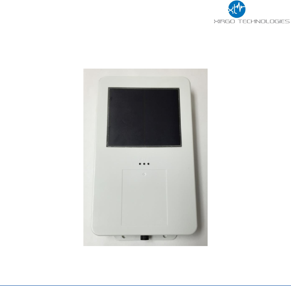
The XT4971A is a solar energy harvesting cellular and GPS tracking device supporting long term,
remote deployments without the need to replace the rechargeable battery. This user guide describes
the physical hardware, associated parts, the different mounting options available, and a quick start-up
procedure.
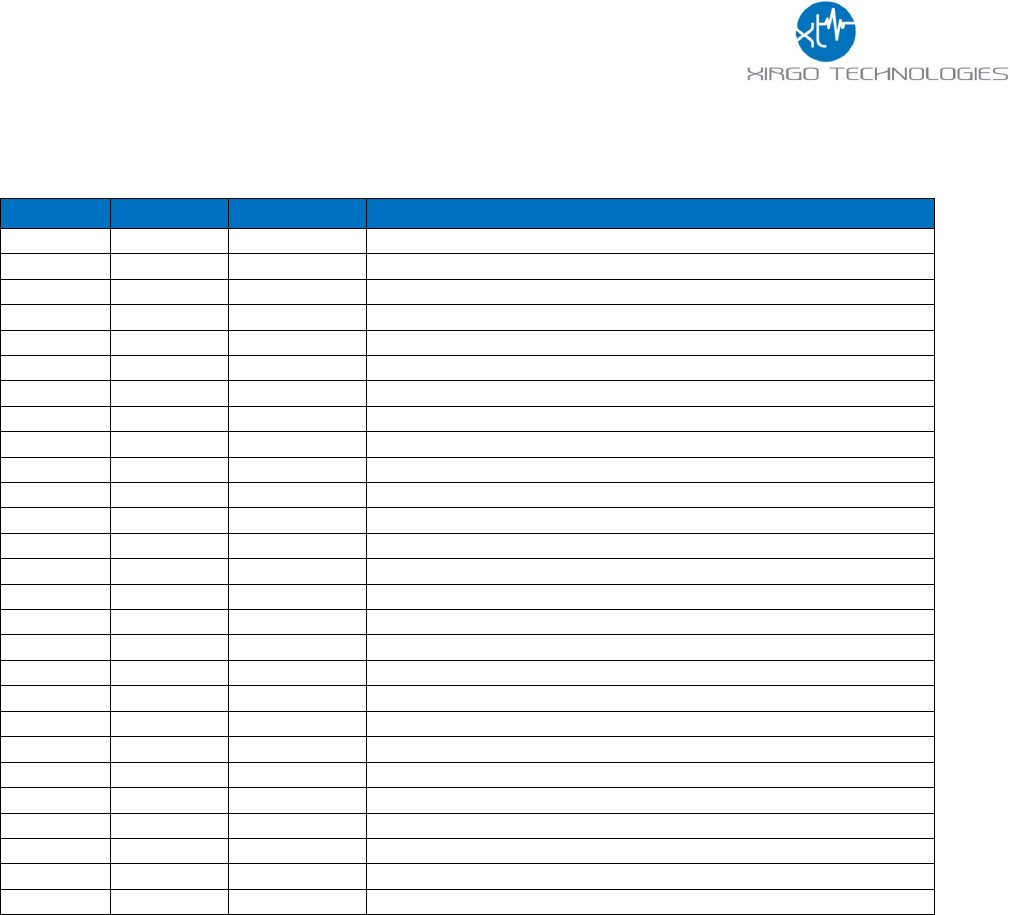
1.1 Feature Matrix
Feature Description
Base Unit
LTE Cellular Communication
✓
GPS Receiver for Tracking Applications
✓
Supports SMS, TCP, UDP, FTP
✓
Over-the-air Configuration and FW Upgrade
✓
Location Polling
✓
Periodic Reporting
✓
Wired or Virtual Ignition On/Off Reporting
✓
Direction Change Alerts
✓
Speed Threshold Alerts
✓
Mileage Threshold Alerts
✓
Main Battery Disconnect Alerts
✓
Heartbeat and Power-up/Reset Alerts
✓
Ignition Idle Alert (wired ignition only)
✓
Towing Start/Stop Alerts(wired ignition only)
✓
Movement Start/Stop Alerts (wired ignition only)
✓
2 Digital Inputs
✓
Park Time Alerts (wired ignition only)
✓
Virtual Odometer
✓
Motion
✓
Sleep/Wake Configuration Settings
✓
Geofence (Radial, Rectangular, and Polygonal)
✓
Device Diagnostics (Battery voltage, connectivity, etc.)
✓
Wireless Sensor Connectivity
✓
5
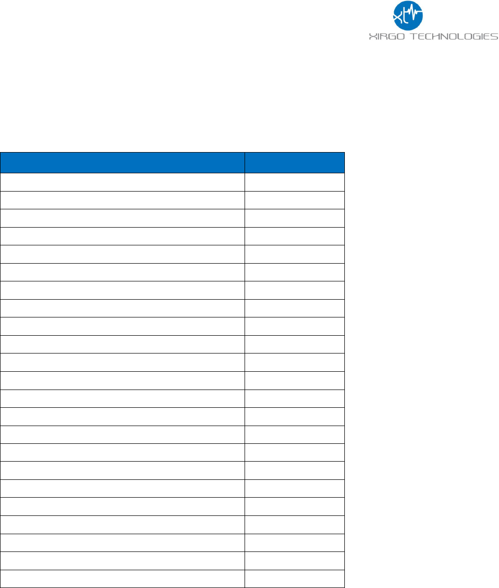
2 Hardware Description
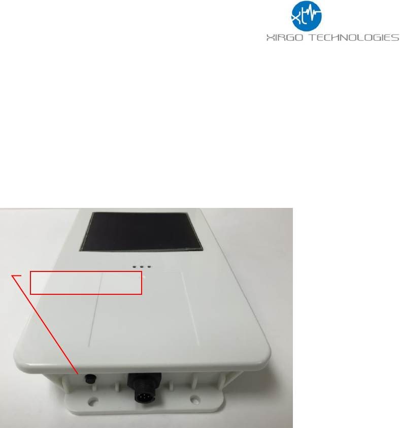
Below is a depiction of key interfaces of the XT4971A:
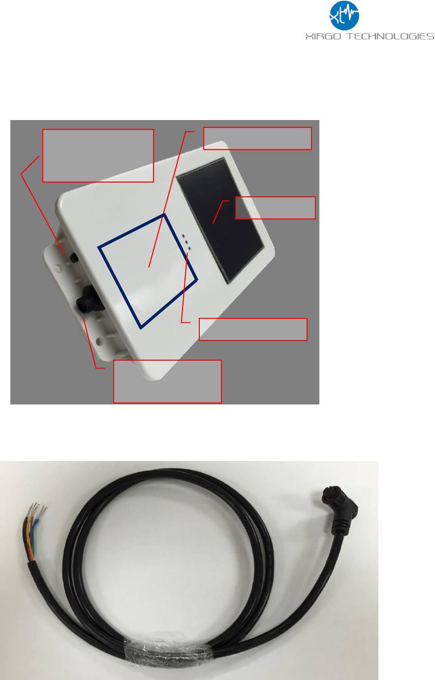
The Associated Cable Harness that interfaces with the unit is shown below:
Solar Panel
Device/FCC Label
Wake-up/
ZigBee Pairing
Button
Zigb
8-Pin Bayonet
Connector
LED Indicators
6
2.1 Hardware Specifications
Cellular Technology Options
LTE
▪ 4G LTE bands: 2,4,5, and 12
GSM
▪ 3G UMTS Band II and Band V
GPS Specification
Receiver channels
▪ 72 channels
Receiver tracking Sensitivity
▪ -167 dBm
Accuracy
▪ +/- 2.0 m CEP (50% , -130 dBm, > 6 Satellites)
Cold Start
▪ 26 sec
Hot Start
▪ 1 sec
Power Requirements
D.C. Power
▪ 8-24V, 12 V nominal
Current Consumption
(4V Supply internal Battery)
▪ 170 µA in sleep state
▪ 80 mA in idle state
▪ 240mA in transmit/receive state
Max. Solar Charge Current
▪ 150mA
Internal Battery
▪ Internal 10600mAh rechargeable Li-Ion
Physical Connection
Interface Connector
▪ 8-pin attached harness
Cellular/GPS Antenna
▪ Internal
SIM Access
▪ Internal
Programming
▪ Serial (RS232 3V logic level)
Mechanical
Case Material
▪ PC and PBT composite
Dimension
▪ 4.7” X 8.5” X 1.1”
Weight
▪ 24 oz.
Operating Temperature
▪ -40°C to +70°C
Certifications
Product
▪ PTCRB
▪ FCC
▪ IC
▪ IP66/IP67
Carrier
▪ AT&T
2.2 Cable Harness Description
7
Pin #
Wire Color
Pin Name
Functional Description
Port Characteristic
1
Blue
VBATT
Ignition Sense
8v to 24v, Internally pulled low
2
Brown
GND
Ground
2.4 to 24V, < 0.2 V
Note: Internally pulled high
3
Yellow
IN2
4
Black
ADC2
8-24 V
5
White
RS232 RX
RS232 Receive Port
3V Logic Interface
Com Port Settings:
Baud rate: 115200 bps; Flow control:
None; 8N1
6
Green
RS232 TX
RS232 Transmit Port
3V Logic Interface
Com Port Settings:
Baud rate: 115200 bps; Flow control:
None;8N1
7
Red
OUT
Output Port (Default Open)
8
White/Black
ADC1
Analog Input
8-24 V
2.3 LED Description
LED
Description
Status
Cellular (Blue)
No Carrier/Denied Registration
OFF
Searching for Cellular Network
Fast Blinking
Registered Roaming
Medium Blinking
Registered Home
Slow Blinking (1Hz)
GPS (RGB Green)
Searching for satellite
Solid
GPS Lock
Slow Blinking (1 Hz)
Zigbee (Auburn)
Pairing Process Initiated
Fast Blinking

8
3 Device Mounting Options
3.1 Screw Mounting
The XT4971A has two flanges (two holes per) at each end of the housing for screw mounting the
device to the mounting surface.
3.2 3M VHB Tape Mounting
For a semi-permanent option, the device can be mounted with 3M VHB tape as shown below:
9
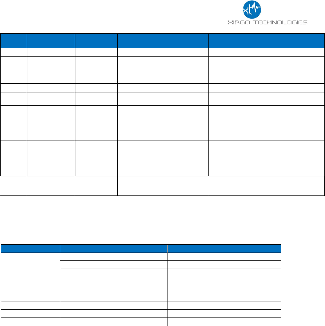
3.3 Trailer Cradle Mounting
An optional trailer mounting cradle can be purchased for easy device mounting for the XT4971A.
The cradle will need to be screw-mounted or VHB Tape mounted to the position desired. The
XT4971A can be easily fastened into the cradle via a Phillips head screw. The angled edged of the
cradle is designed to withstand the impact of snow scrapers that may come in contact to the
cradle if mounted on the top of a typical trailer.
3.4 Container Cradle Mounting
An optional container cradle can be purchased for easy device mounting for the XT4971A. The
cradle will need to be screw-mounted or VHB Tape mounted to the position desired. The
XT4971A can be easily fastened into the cradle via a Phillips head screw. The shape of the cradle
is designed to fit in the corrugations of an ISO standard freight container.
10
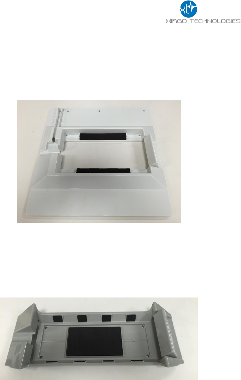
3.5 Device Mounting Guidelines
The XT4971A Series devices leverage solar energy to replenish the charge of its battery. Please
consider the device mounting guidelines to maximize device solar charging. Also, the XT4971A
series uses cellular and GPS technologies whose signal reception quality is depending on
mounting location and style. Adhering to these guidelines will optimize the field performance of
the XT4971A:
• If possible, have the solar panel facing directly towards the noon sun. At least have the
solar panel no greater than 90° away from the noon sun.
• Avoid mounting the XT4971A were shadows may cast upon the solar panel
• Avoid placing unit inside a container made from any conductive materials or partially
mounted into a bracket made from any conductive materials. Doing so may potentially
degrade GPS and cellular reception.
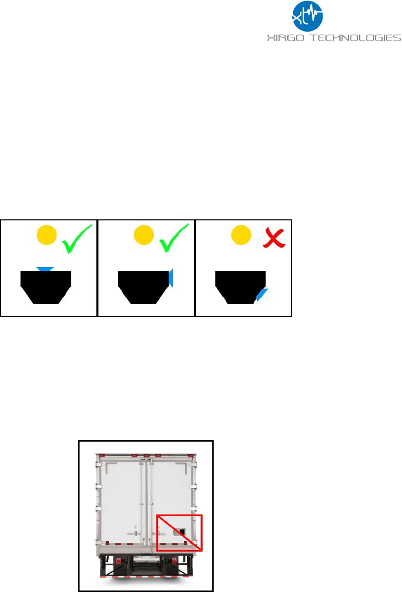
• Avoid mounting the XT4971A in low locations where dirt, grease, or any other staining
particles can be introduced by rotating wheels. Excess dirt, grease, or staining materials on
the solar panel will reduce the amount of charge the device can receive.
• Avoid mounting the XT4971A to locations that are high risk to predictable physical harm.
(I.e. do not mount the unit on the top of an asset if snow scrapers are utilized in periodic
maintenance of the asset without some sort of protective bracket)
11
4 Quick Start Guide
4.1 Device Wakeup
To start up the device, simply hold the black button located near the circular connector on the
side panel of the device for 3 seconds. You should see the blue “C” LED light up and then fade out.
The blue LED will blink when the device is successfully connected to the network. Refer to table
in section 2.3 for LED behavior.
Note: The factory default settings are configured to have the device to sleep within 2 minutes of
wake. Consider pulling the IN1 wire high to keep the device awake for configuration purposes or
disable sleep by issuing the proper 3017 command.
Wake up Button

12
4.2 Configuring the Device via SMS
1) Ensure your device is active on your cellular account.
2) Awaken device from sleep XT4971A via the “wake-up” button.
3) If the device needs more power, then supply 12V DC via the red wire of the cable harness.
4) Ensure device cellular LED is blinking based on LED definition in this document.
5) Using your mobile phone or SMS gateway send +XT:1008 command to the device MDN
6) Command: “+XT:1008,<SM>”- Sets SMS Number
7) Response (via SMS): $$<UID>,<1008>,<SM>##
8) Once you have set SMS to reply to your mobile or gateway, you can now send other
commands to device via SMS per device protocol documentation.
a. Command +XT:1010 configures network settings
b. Command +XT:3017 configures the sleep/wake mode for the device.
i. The factory defaults for this device is to operate in the sleep timer mode and
have a minute of wake time max. You may need to temporarily disable sleep
in order to configure the unit uninterrupted by sleep.
c. Command +XT:3040 and +XT:3042 configure alert and threshold settings
9) +XT:7008,<PF> saves device configuration to permanent memory. You may configure
individual features and the 7008 command will save all the configuration state at that
instance.
4.3 Configuring the Device via PC
1) A RS-232 to USB TTL converter cable is required to connect a XT-4550 device to a
computer for local configuration. Connect the XT4971A Tx wire to the TTL converter
cable Rx wire. Connect the XT4971A Rx wire to the TTL converter cable Tx wire. Connect
the XT4971A ground wire to the ground wire of the TTL converter cable. Use a terminal
application to connect to the COM port associated with the TTL converter cable.
2) Use the following terminal application settings:
a. Bits per second: 115200
b. Data bits: 8
c. Parity: None
d. Stop bits: 1
e. Flow control: None
3) Press enter 3 times to activate the Aux Port. The print “Aux Port Active” will show up on
your terminal console when activated successfully.
4) Once Aux Port is active enter the password: XIRGOTECH611
5) The terminal console will print ACCEPTED when password is input successfully.

13
6) You can now configure the device by sending the XT commands listed in the protocol
document of this device.
a. Command +XT:1010 configures network settings
b. Command +XT:3017 configures the sleep/wake mode for the device.
i. The factory defaults for this device is to operate in the sleep timer mode and
have a minute of wake time max. You may need to temporarily disable sleep
in order to configure the unit uninterrupted by sleep.
c. Command +XT:3040 and +XT:3042 configure alert and threshold settings
7) +XT:7008,<PF> saves device configuration to permanent memory. You may configure
individual features and the 7008 command will save all the configuration state at that
instance.
4.4 Download Over the Air (DOTA) Firmware Update Guide
This devices supports firmware updates over the air. Customers must have an FTP server and
the FTP server must be configured for active mode. The procedures for DOTA are as follows:
1) Make sure that the +XT:1010 network settings are valid and that the device is able to send
and receive data with the APN configured.
2) Configure the FTP network settings via the +XT:1004 command.
3) Check that the settings are correct by querying via the +XT:1005 command
4) Make sure the FTP server is in active mode and the correct EBF file is located in the folder
that you have set in your FTP network settings.
5) Send the unit the +XT:1006 command to initiate the OTA update. Refer to the protocol
document for the proper syntax for this command. The .ebf extension is not used in this
command. The file names are case sensitive.
6) If the device cellular network settings are compatible from the old firmware to the new
firmware, then you will receive a 1007 reply signifying the completion of the update.
Notes:
• If are upgrade to a new firmware release and parameters have been added the original settings will be
erased. The 1000, 3000, 5000 and 7000 series settings will be reset to default. Always reference release
notes before initiating a firmware upgrade.
• Disable sleep mode prior to a download
• Do not download older firmware into newer devices

14
FCC/IC:
REGULATORY COMPLIANCE INFORMATION
This equipment with FCC-ID: GKM-XT4971A and IC-ID: 10281A-XT4971A, HVIN: XT4971A
is subject to the Federal Communications Commission (FCC) and Industry Canada (IC) rules.
Changes or modifications not expressly approved by the party responsible for compliance could void the user's
authority to operate the equipment.
This device complies with Part 15 of the FCC Rules and with license exempt Radio Standard Specifications of
Industry Canada.
Operation is subject to the following two conditions:
(1) this device may not cause harmful interference, and
(2) this device must accept any interference received, including interference that may cause undesired
operation.
Les changements ou modifications non expressément approuvés par la partie responsable de la conformité
pourraient annuler l'autorité de l'utilisateur à utiliser l'équipement.
Le présent appareil est conforme aux CNR d'Industrie Canada applicables aux appareils radio exempts de
licence. L'exploitation est autorisée aux deux conditions suivantes :
(1) l'appareil ne doit pas produire de brouillage, et
(2) l'utilisateur de l'appareil doit accepter tout brouillage radioélectrique subi, même si le brouillage est
susceptible d'en compromettre le onctionnemen
Radio frequency radiation exposure Information:
This equipment complies with FCC and IC radiation exposure limits set forth for an uncontrolled
environment. This equipment should be installed and operated with minimum distance of 20 cm
between the radiator and your body. Co-location of this radio device with other radio transmitters may void it's
compliance with the said RF exposure limits and would have to be subject to re-assessment.