Xirgo Technologies XT6000 REEFER CONTAINER MONITORING DEVICES User Manual EFS Proposal
Xirgo Technologies Inc. REEFER CONTAINER MONITORING DEVICES EFS Proposal
UserManual.wiki
>
Xirgo Technologies
>
XT6000 User Manual
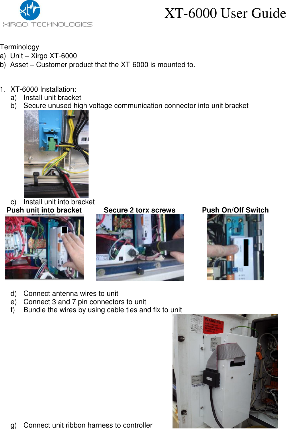
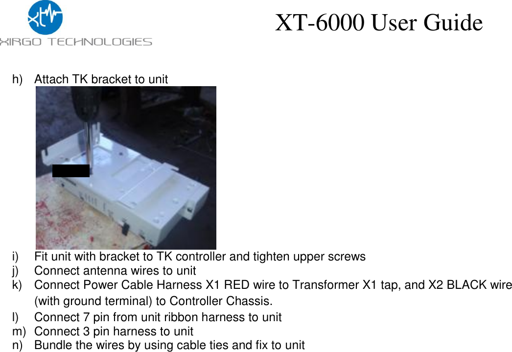
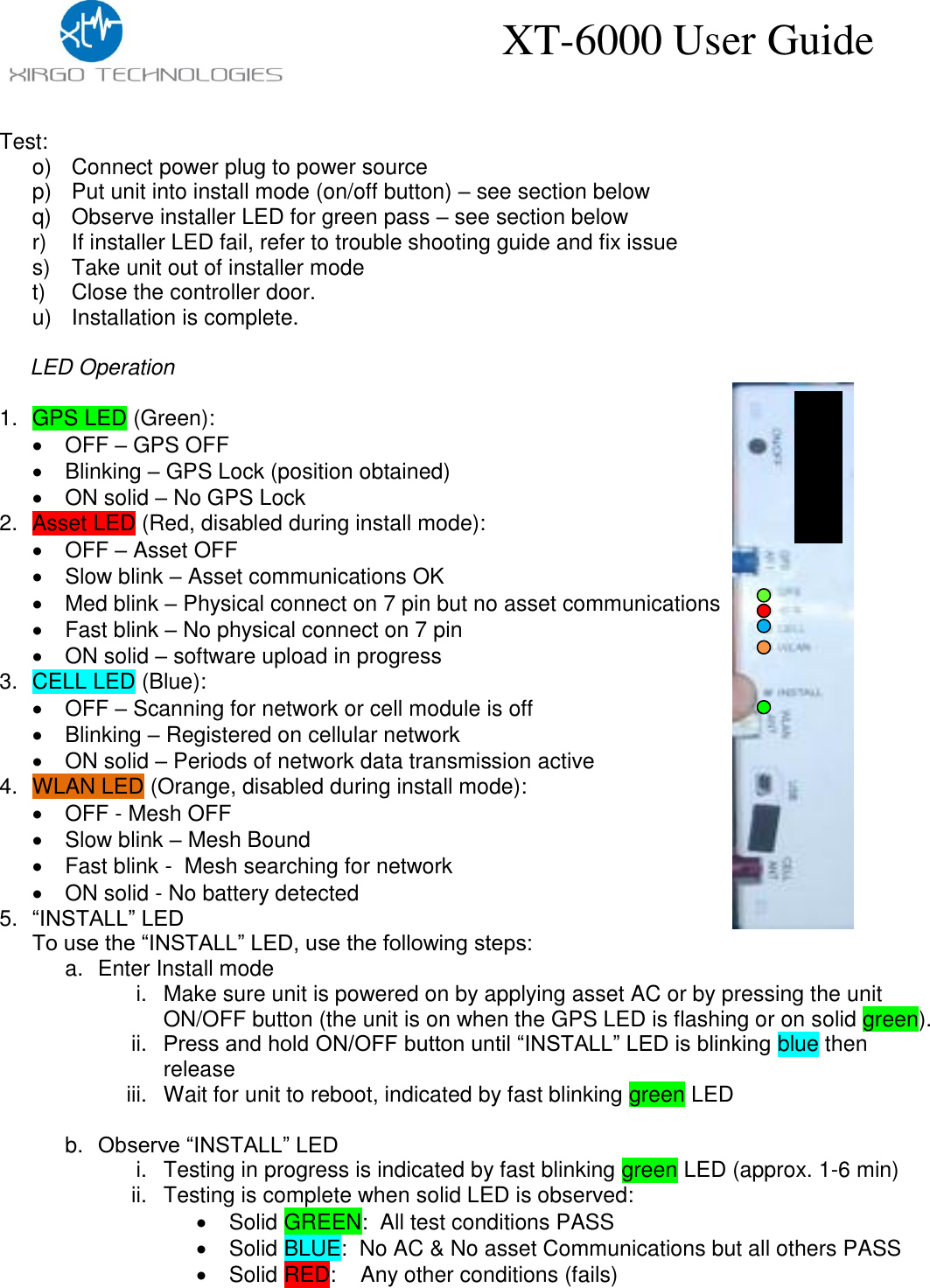
User Guide
Navigation menu
Upload a User Manual
Namespaces
Wiki Guide
HTML
PDF
Info
Views
User Manual
Discussion / Help
Navigation