Xirgo Technologies XT6360 Vehicle GPS/Cellular Tracking Device with BT User Manual
Xirgo Technologies Inc. Vehicle GPS/Cellular Tracking Device with BT
UserManual.wiki
>
Xirgo Technologies
>
XT6360 User Manual
User Manual
Navigation menu
Upload a User Manual
Namespaces
Wiki Guide
HTML
PDF
Info
Views
User Manual
Discussion / Help
Navigation
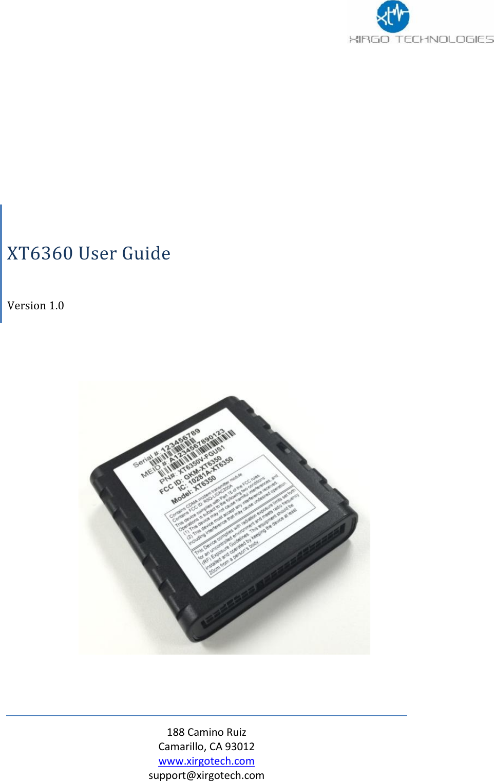

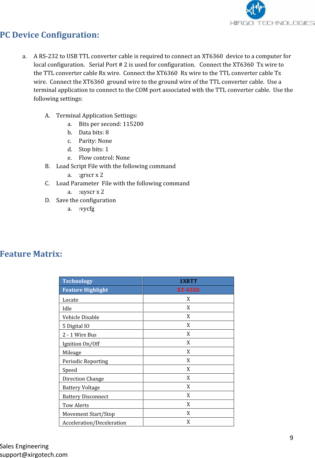
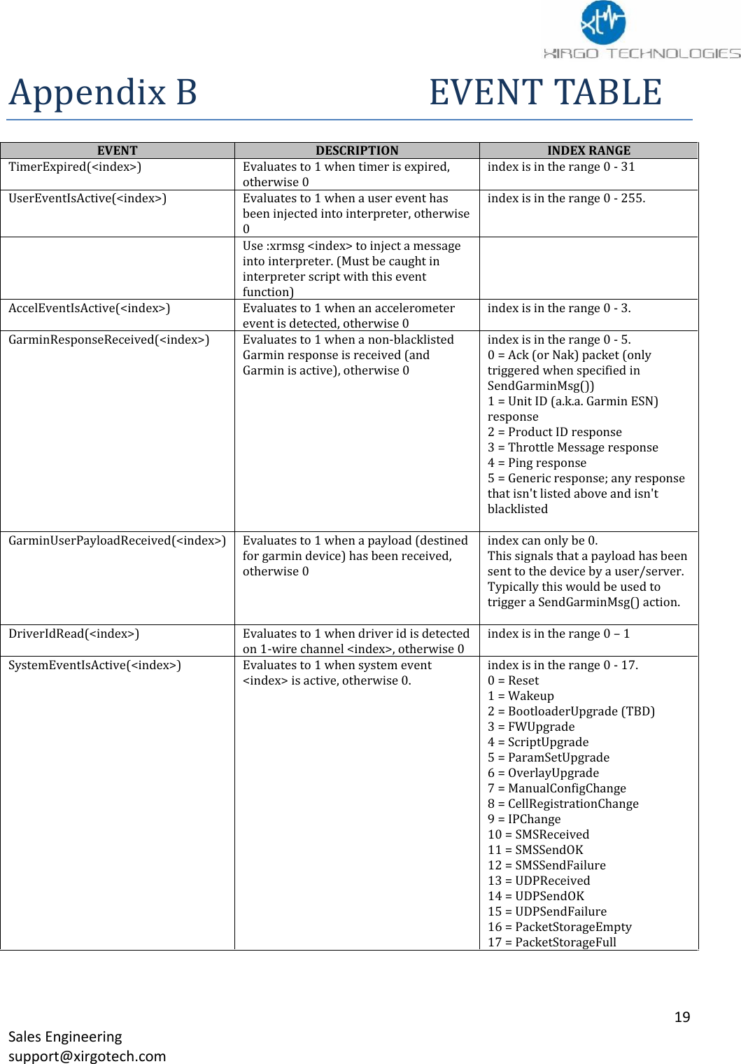
![10Sales Engineeringsupport@xirgotech.comDevice ConfigurationThe XT6360 is a full-feature device based on a platform that allows rapid customization by market andapplication requirements. The XT6360 series offers highly configurable firmware which allows full controlof device reporting behavior. The customizable messages provides only the data req uired to support uniqueand evolving business needs. The XT6360 configuration is accomplished by loading 2 files:Script FileParameter FileThe Script File is the file that triggers the alerts and actions of the XT6360 .The Parameter File specifies values used to configure hardware peripherals, network behavior, and inputsto core functionality of the XT6360 .Script FileA Script file can contain an unlimited number of Triggers. When scripting the Triggers are groupinto individual Trigger blocks. A trigger block is comprised of the following sections:TriggerConditional Actions - optionalActionsEXAMPLE:trigger when Eq(InputState(0), 1) [Debounce(0, 0)]condact alwaysactionsrun BuildAndSendMsg(0, 2, 0, 0)DESCRIPTION:When ignition goes high a message is sent to the server.Important notes on Scripting:Park TimeXVirtual OdometerXQuick FenceXDevice DiagnosticsXMotionXAccelerometerXGeo-Zones50 CircularBack Up Battery250mAhCommunication ProtocolTCP, UDP , UDPwACKFirmware DownloadFTP](https://usermanual.wiki/Xirgo-Technologies/XT6360/User-Guide-2621508-Page-11.png)
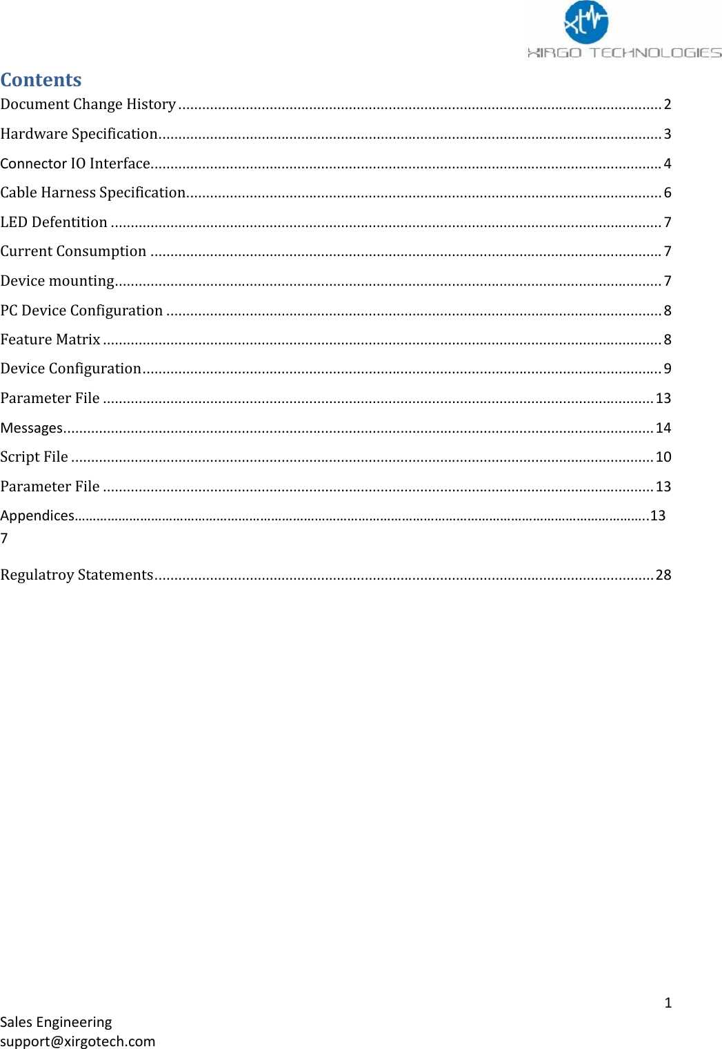
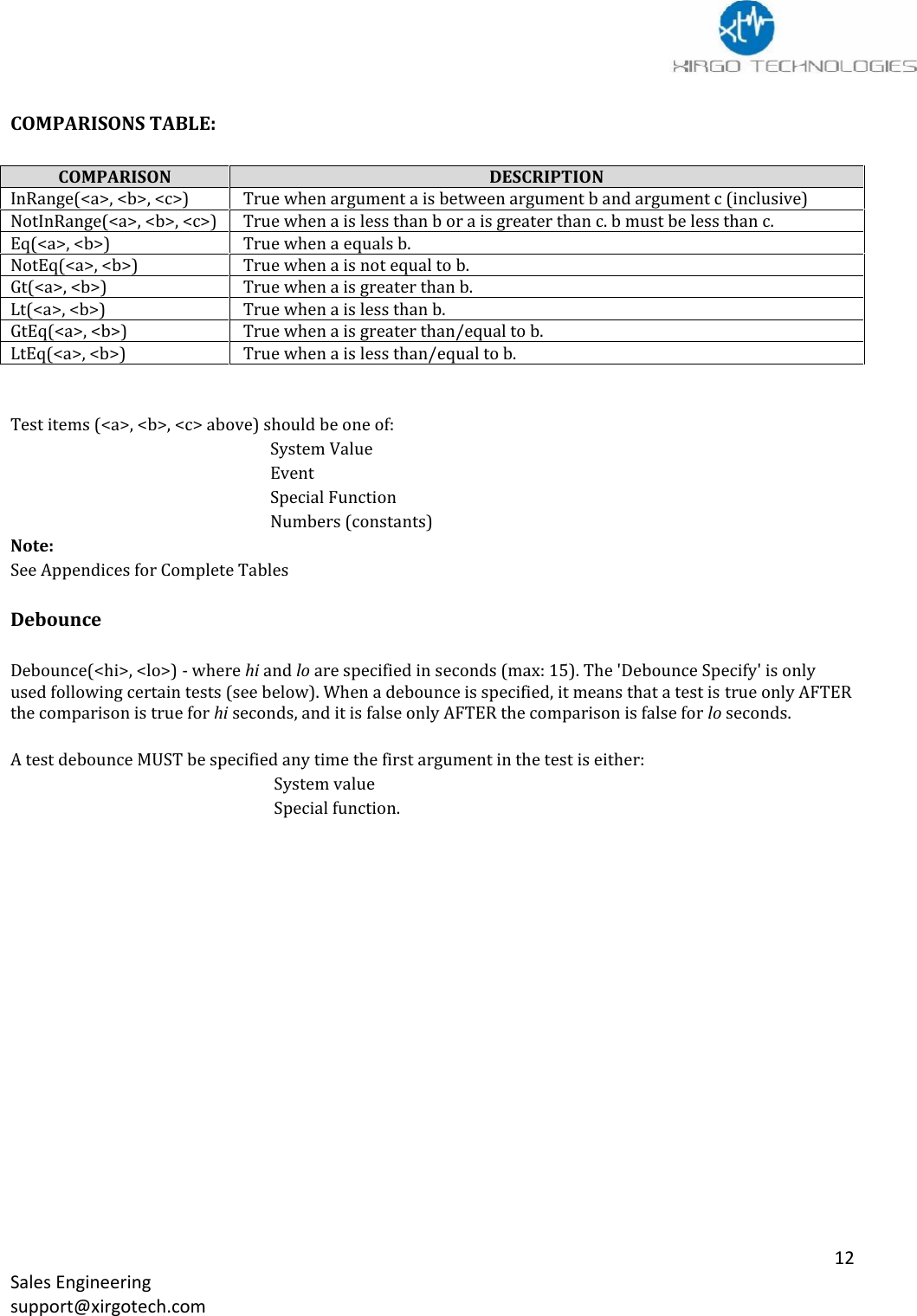
![11Sales Engineeringsupport@xirgotech.com1. Each Trigger Block has one Trigger.2. The Trigger must test true for an action to occur.3. A test is usually made of one comparison. See Comparison table.4. Each Trigger Block can contain unlimited Conditional Action Blocks.5. Trigger Blocks and Conditional Action block will use the following when building a script:a. System Valuesb. Eventsc. Special Functionsd. Numbers6. Each Conditional Action Block may optionally contain one Conditional Action Block Test.7. A Conditional Action Block Test may contain up to 5 comparisons (Using same “any” or “all” logic as describedfor Trigger Block Test).8. Each Conditional Action Block must contain one Action Block.How Trigger Block Tests WorkEach Trigger Block is entered when the Trigger Block Test becomes true. Note that the Trigger Block is NOTentered WHILE the Test IS true, only the moment it becomes true. For example if you want to trigger actionswhen vehicle speed goes above 80 km/hr:trigger when Gt(GPSSpeed, 80) [Debounce(0, 0)]The interpreter will enter the trigger block at the moment the vehicle speed increases above 80 km/hr. It willnot continue to enter the trigger block during subsequent evaluations where the speed remains above 80km/hr. Once the speed drops below 80 (for at least one evaluation), then the trigger block will be enteredagain next time the speed increases above 80 km/hr.Note that if the speed oscillates between 80.0 and 80.1 km/hr it is po ssible to cause the actions to be executed asfrequently as the speed oscillates. In order to avoid this, make use of the debounce specifiers.How Conditional Action Block Tests WorkUnlike Trigger Block Tests, Conditional Action Block Tests allow the action to be performed WHILE the test istrue. Continuing with the example above, let's say we want to further limit our actions to only execute themoment speed goes above 80 km/hr AND only when the vehicle heading is within 10 degrees of North:trigger when Gt(GPSSpeed, 80) [Debounce(0, 0)]condact any InRange(GPSHeading, 3500, 3600) [Debounce(0, 0)]InRange(GPSHeading, 0, 100) [Debounce(0, 0)]actionsAll Conditional Action blocks are independent. One is not dependent on the other.Condact Always This means the actions inside a Conditional Action Block will ALWAYS run when thetrigger Block's test(s) are true.Condact When When only one comparison is usedCondact Any The test is true when ANY of the comparisons is true.Condact All - ALL comparisons must be true for test to be true.](https://usermanual.wiki/Xirgo-Technologies/XT6360/User-Guide-2621508-Page-12.png)
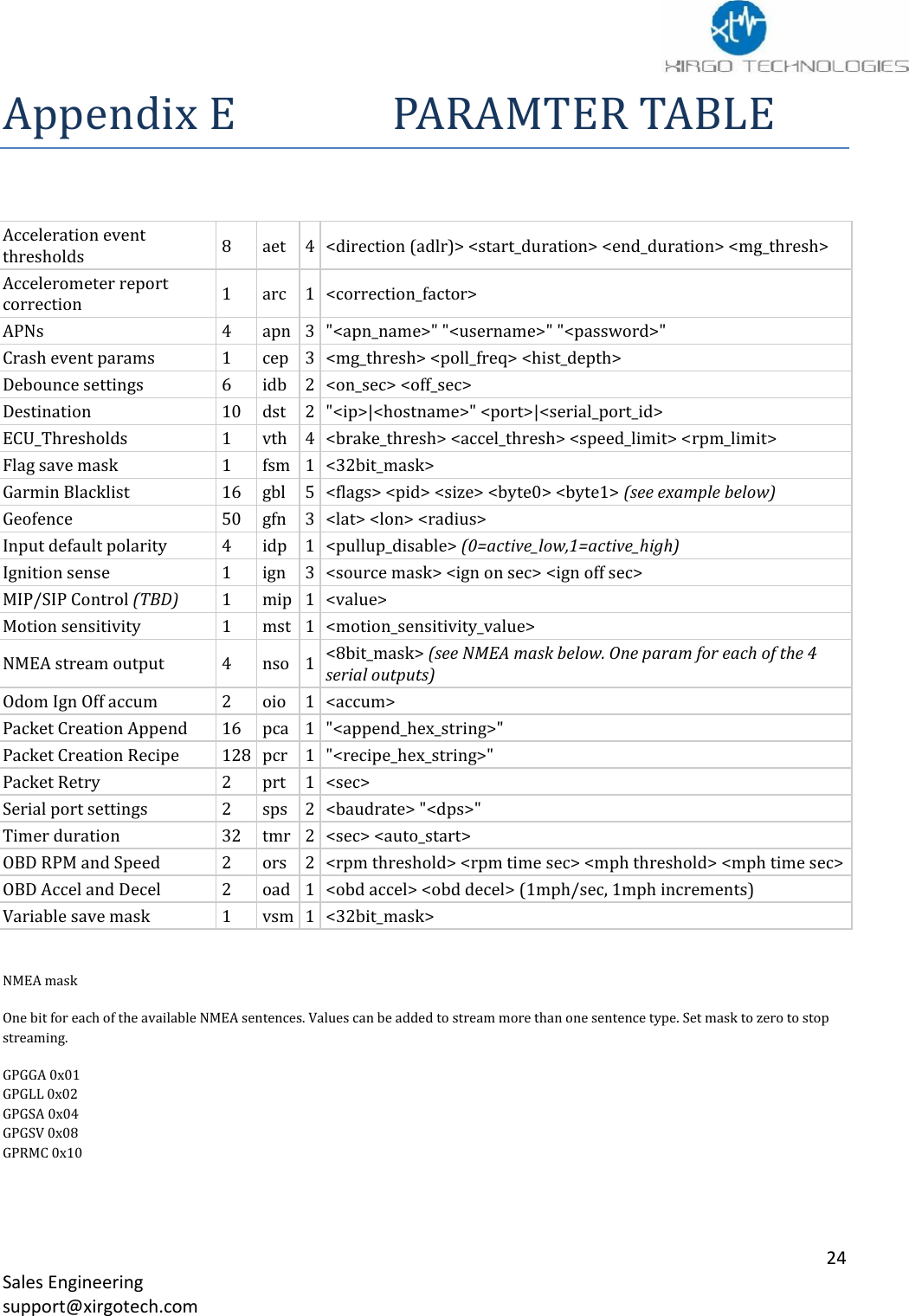
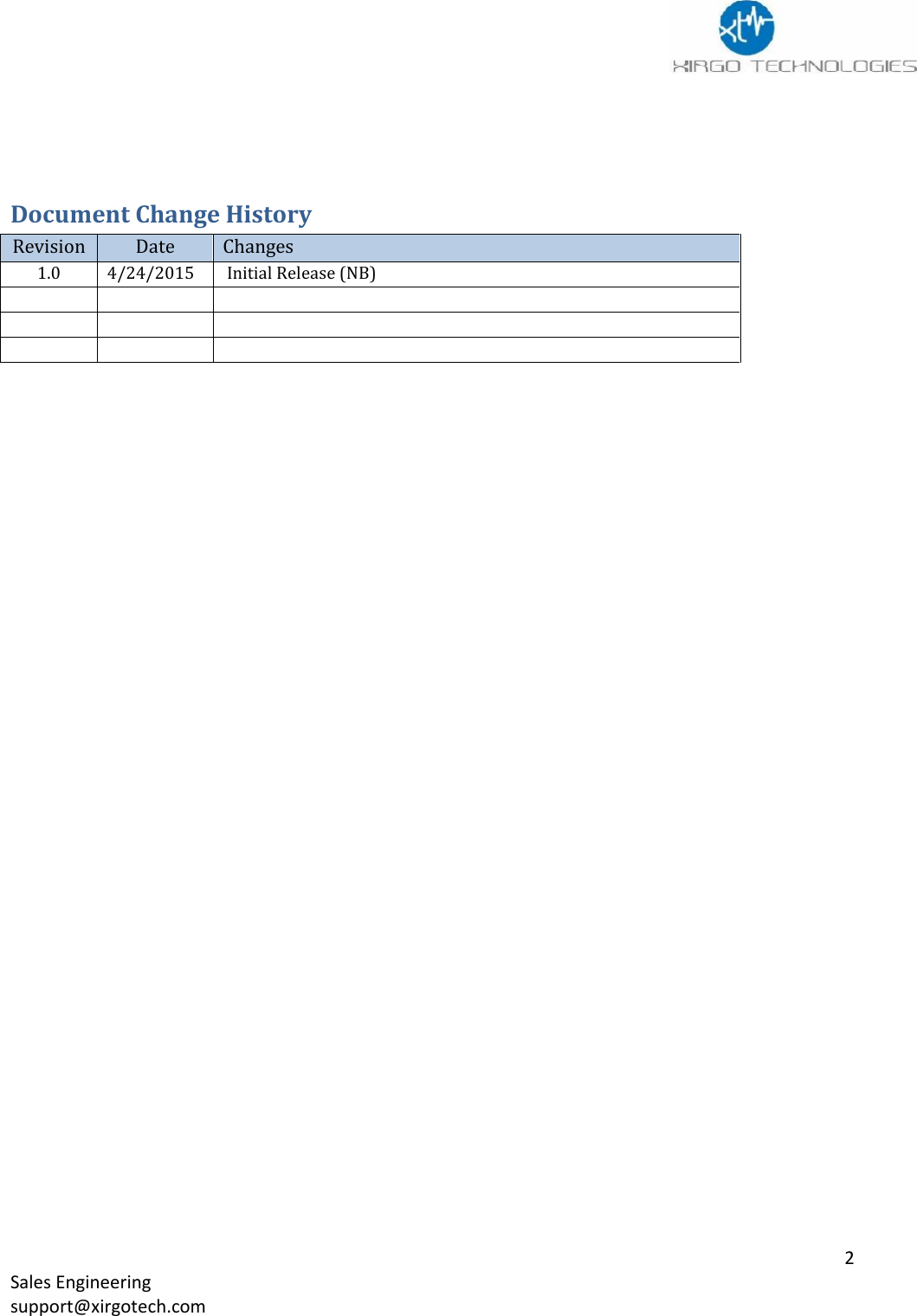
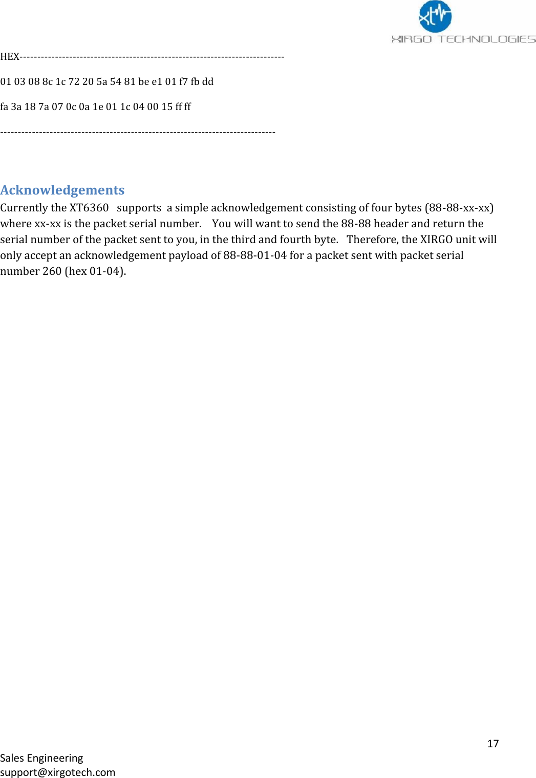
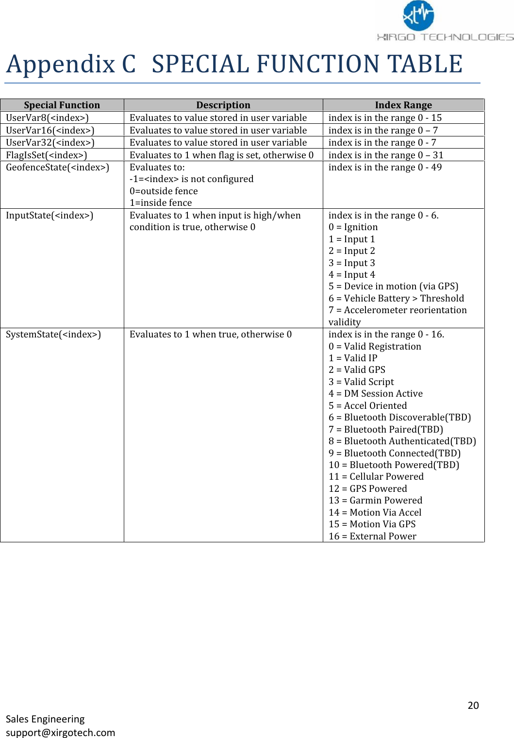
![13Sales Engineeringsupport@xirgotech.comParameter FileThe parameter file is the setting for all of the XT6360 hardware peripherals, network behavior, andinputs to core functionality of the XT6360. The following table contains all the parameters that can beconfigured in a XT6360:Acceleration eventthresholdsAccelerometer reportcorrectionAPNs (GSM only)Crash event paramsDebounce settingsDestinationECU_ThresholdsFlag save maskGarmin BlacklistGeofenceInput default polarityIgnition senseMIP/SIP Control (TBD)Motion sensitivityNMEA stream outputOdom Ign Off accumPacket Creation AppendPacket Creation RecipePacket RetrySerial port settingsTimer durationOBD RPM and SpeedOBD Accel and DecelVariable save maskSee Appendix C for Parameter settings.Creating a Parameter File:1. The parameter settings are written and saved as a .txt file.2. Use :wycfg in front of the parameter your are configuring.3. To load the parameter file you can use XDMI or load the file over Serial Port 2.a. Load via Serial port use the following commandsi. :uyscr x 2 load the fileii. :vycfg Save the parameter fileBelow is an example of a parameter file.:wycfg pdo 0 1:wycfg dst[0] "71.24.53.116" 65534:wycfg dst[9] "none" 65535:wycfg pcr[0] "00080104030607080b17":wycfg pcr[1] "01050103070809":wycfg pcr[2] "02140104535455565758595a5b5c5d5e5f6061622c2e":wycfg pcr[3] "030701040305060708":wycfg pcr[4] "040701040305060708":wycfg pcr[5] "050701040305060708":wycfg pcr[6] "06080104030607080b17":wycfg pcr[7] "07080104030607080b17:wycfg pcr[8] "08040104060c":wycfg tmr[0] 90 1:wycfg tmr[1] 90 1:wycfg aet[0] 0 1000 1000 205](https://usermanual.wiki/Xirgo-Technologies/XT6360/User-Guide-2621508-Page-14.png)
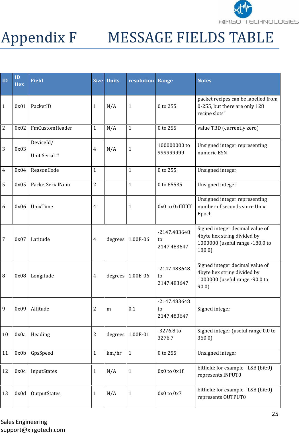
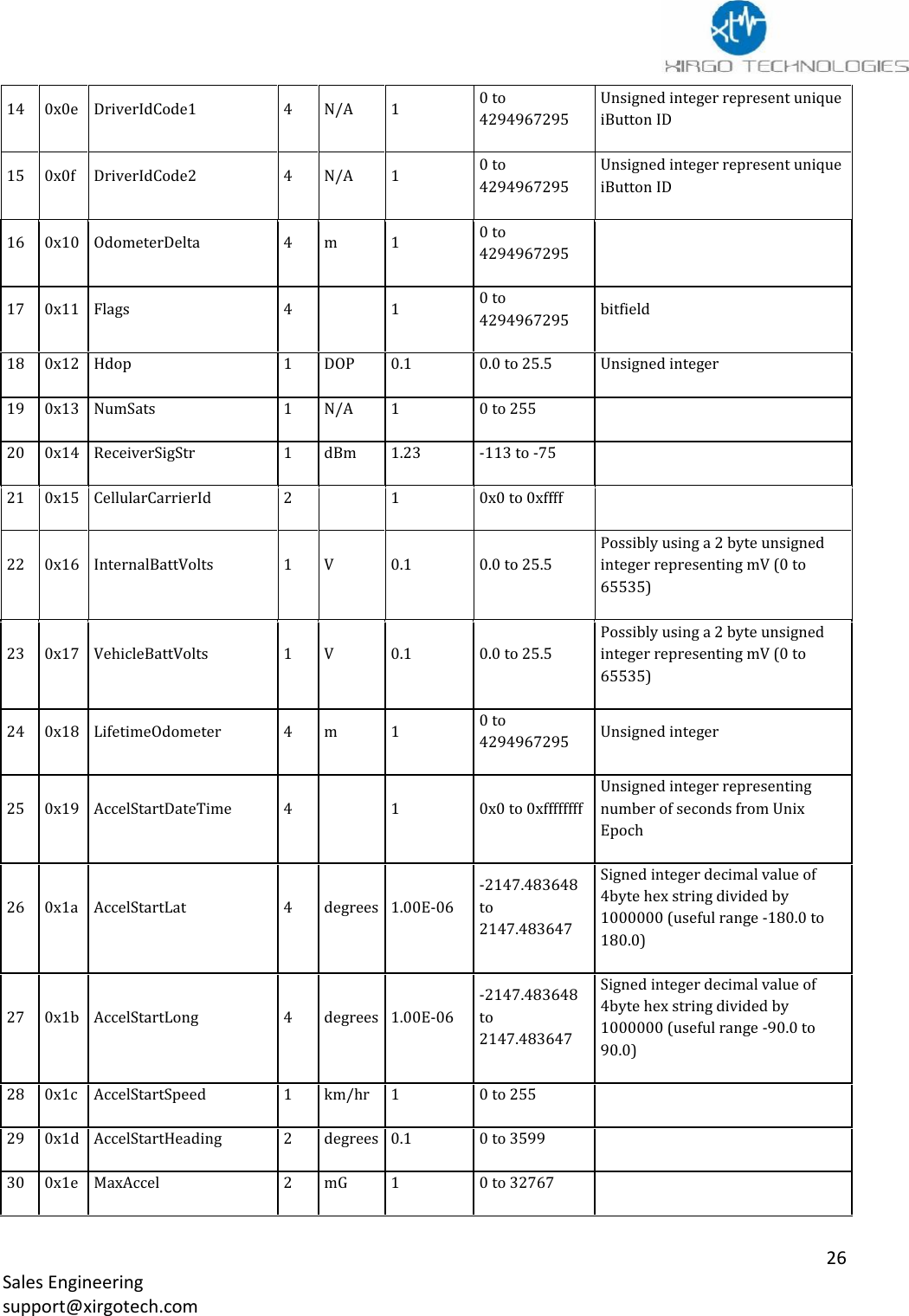
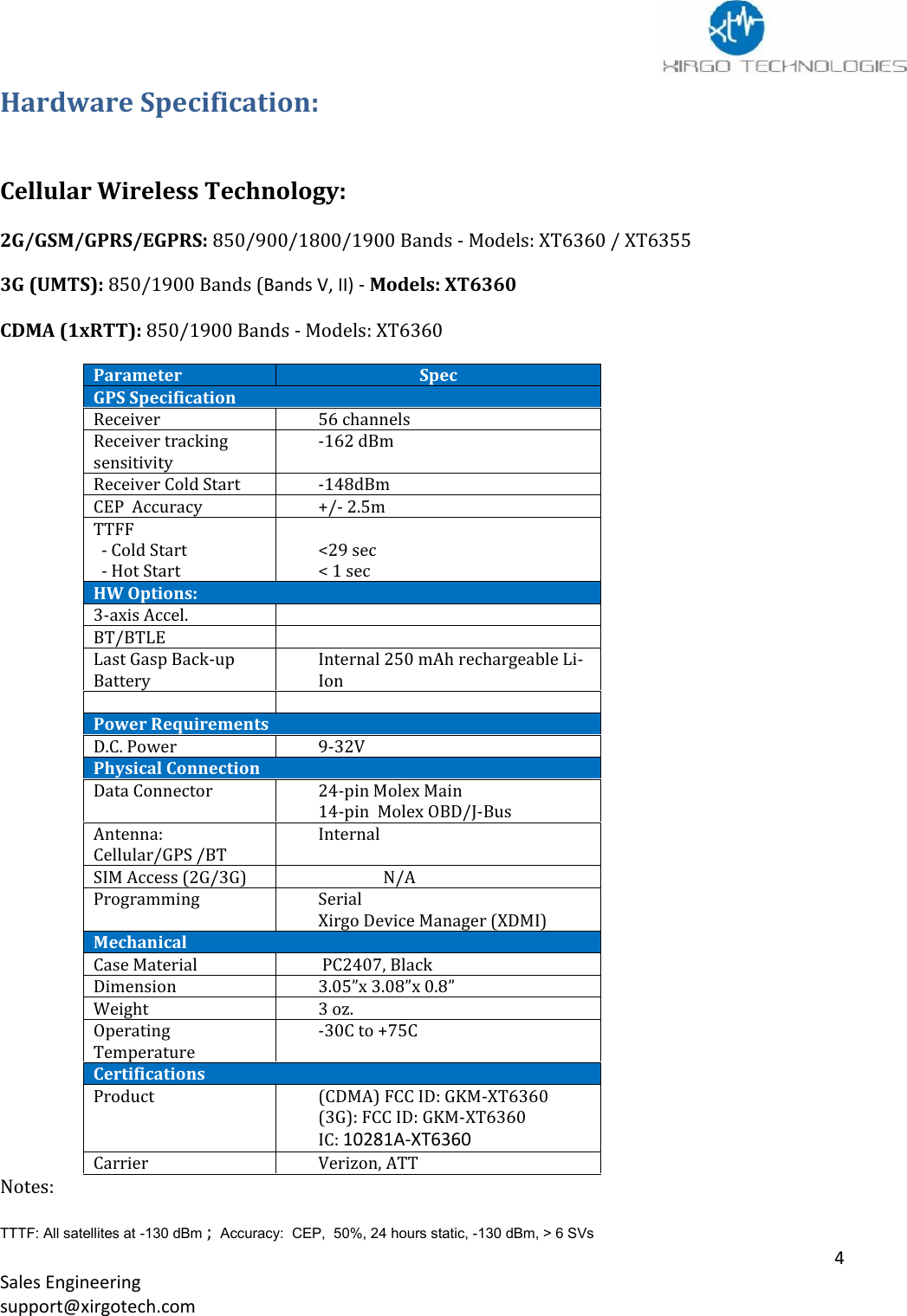
![14Sales Engineeringsupport@xirgotech.comMessagesHow to create a MessageThe XT6360 custom message allows users to select what fields of data to be sent in a message whentriggered. A message can contain up to 40 data fields and you can have up to 128 different messages.Refer to Appendix F - Message Field TableWhen defining a Message use the following syntax:pcr[<slot_index>] "<recipe_hex_string>"where:o<slot_index> is in the range 0 - 127o"<recipe_hex_string>" is a quoted string of hexadecimal bytes (represented by two asciicharacters) The Message Field Table in Appendix F contains the Hex values for theindividual fields that can be selected to create the Packet.String format: "<recipe_id><num_fields><field_0><field_1>...<field_N>"EXAMPLESpcr[0] "0003010306"opcr slot 0 will contain a Recipe string with 3 fields: PacketID, DeviceID, and GpsSpeedrecipe_hex_string -"000301030b"RecipeID 00 (Hex)Number of fields 03 (Hex)Field 0 is Packet ID 01 (Hex)Field 1 is DeviceID 03 (Hex)Field 2 is GpsSpeed 0b (Hex)Notes:oThe device can store and use 128 pcr (messages):wycfg pcr[0] …. :wycfg pcr[127]RecipeID is always in Hex.pcr[1] "14050103070809"opcr slot 1 will contain a Recipe string with 5 fields : PacketID, DeviceID, Latitude, Longitude,and Altituderecipe_hex_string -"14050103070809"RecipeID 01Number of fields 05Field 0 is Packet ID 01Field 1 is DeviceID 03Field 2 is Latitude 07Field 3 is Longitude 08Field 4 is Altitude 09](https://usermanual.wiki/Xirgo-Technologies/XT6360/User-Guide-2621508-Page-15.png)
![15Sales Engineeringsupport@xirgotech.com:wycfg pcr[254] "fe0401031213"oPCR slot 2 will contain a Recipe string with 4 fields: PacketID, DeviceID, Hdop, and NumSatsrecipe_hex_string -" fe0401031213"RecipeID feNumber of fields 04Field 0 is Packet ID 01Field 1 is DeviceID 03Field 3 is Hdop 12Field 4 is Numsats 13Decoding a MessageKnowing the Reason Code and Packet Id you will know how to parse your data. These 2 fields willlet you know what triggered the message, what data is being sent, and in what order you’rereceiving the data. Refer to Appendix F for a complete list of Fields available. The table containsformatting information on the data in each field. Data is sent in Binary via UDP andacknowledgments can be used.Reason Code – Number to identify what triggered message was sentExamples of Reason Codes:Reason # Description01 Ignition On02 Periodic Report when Ignition On03 Ignition Off04 Periodic Report when Ignition Off05 Direction Change06 Speed Threshold Alert07 Acceleration Report08 Deceleration Report09 Idle Report10 Movement Start Report11 Movement Stop Report12 Park Time AlertNote:A Reason number is like the Event number you have in a XT2060.4001: Periodic location reporting with ignition ON](https://usermanual.wiki/Xirgo-Technologies/XT6360/User-Guide-2621508-Page-16.png)
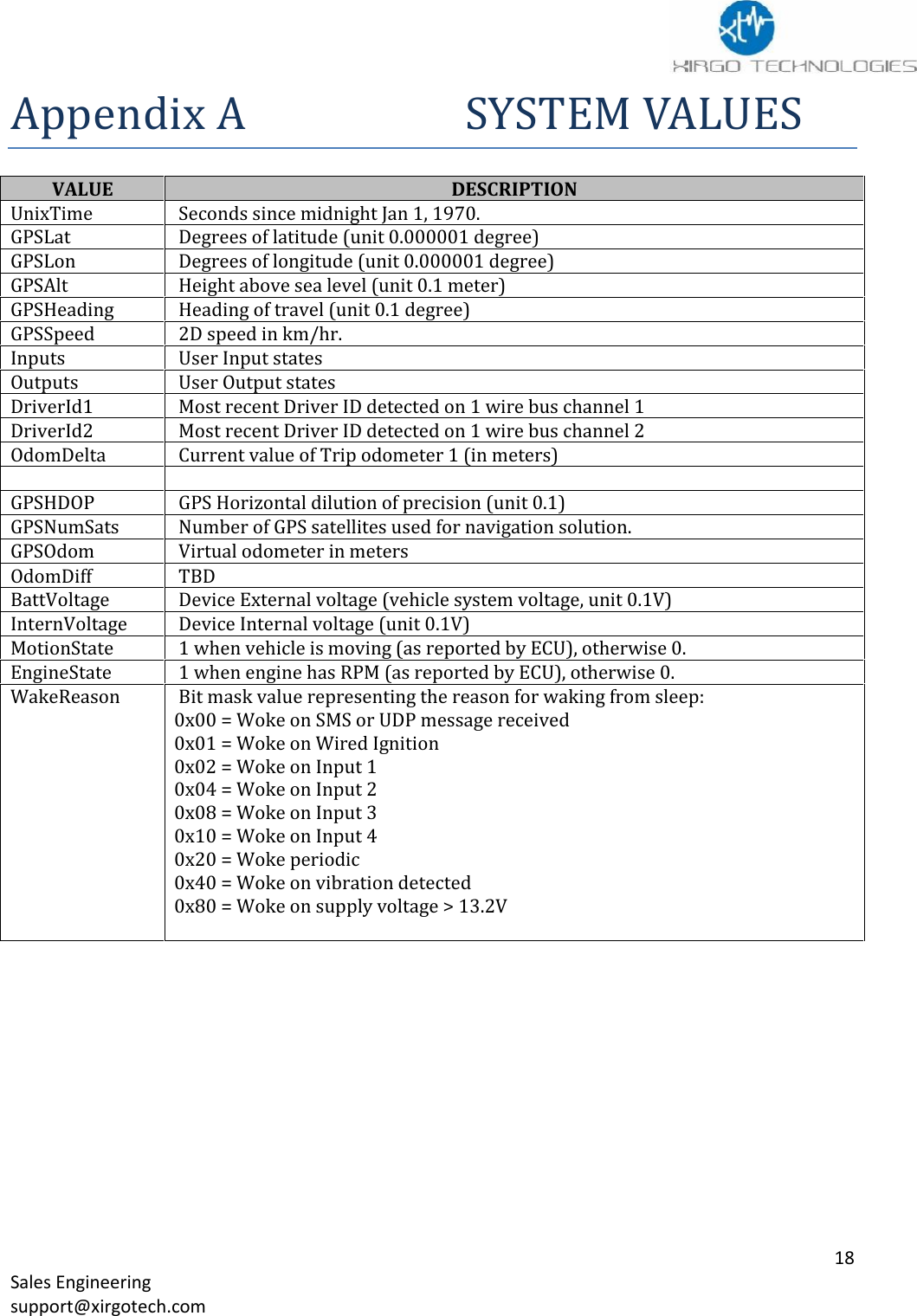
![16Sales Engineeringsupport@xirgotech.compcr BreakdownA pcr is a list of fields that will be used to create a message to be sent from the XT6360 to the server.Each packet recipe can contain up to 40 fieldsThe device can store 128 packet recipespcr[<slot_index>] "<recipe_hex_string>"<slot_index> is in the range 0 - 127"<recipe_hex_string>"is a quoted string of hexadecimal bytes (represented by two ascii characters)String format: "<packet_id><num_fields><field_0><field_1>...<field_N>"Example:pcr 1 will contain a 5 fields : PacketID, DeviceID, Latitude, Longitude, and Altitudepcr[1] "01050103070809"RecipeID 01Number of fields 05Field 0 is Packet ID 01Field 1 is DeviceID 03Field 2 is Latitude 07Field 3 is Longitude 08Field 4 is Altitude 09Below is an example of a packet recipe that is partially decoded.EXAMPLE:pcr[1] "010E01040305060708090a0b12131415"(all values below are in Hex)Recipe ID 01Number of fields 0EField HEX ID Value Parsed CommentPacketID 01 01 01ReasonCode 04 03 03 (IGN. OFF MESSAGE)Serial # 03 088c1c72 143400050 Unit Serial NumberPacketSerialNum 05 205a 8282Etc..DATA FROM DEVICE CONVERTED FROM BINARY TO HEX USED IN TABLE ABOVEdatagram: 4 from 75.255.159.0:3000 (size: 31 bytes)](https://usermanual.wiki/Xirgo-Technologies/XT6360/User-Guide-2621508-Page-17.png)
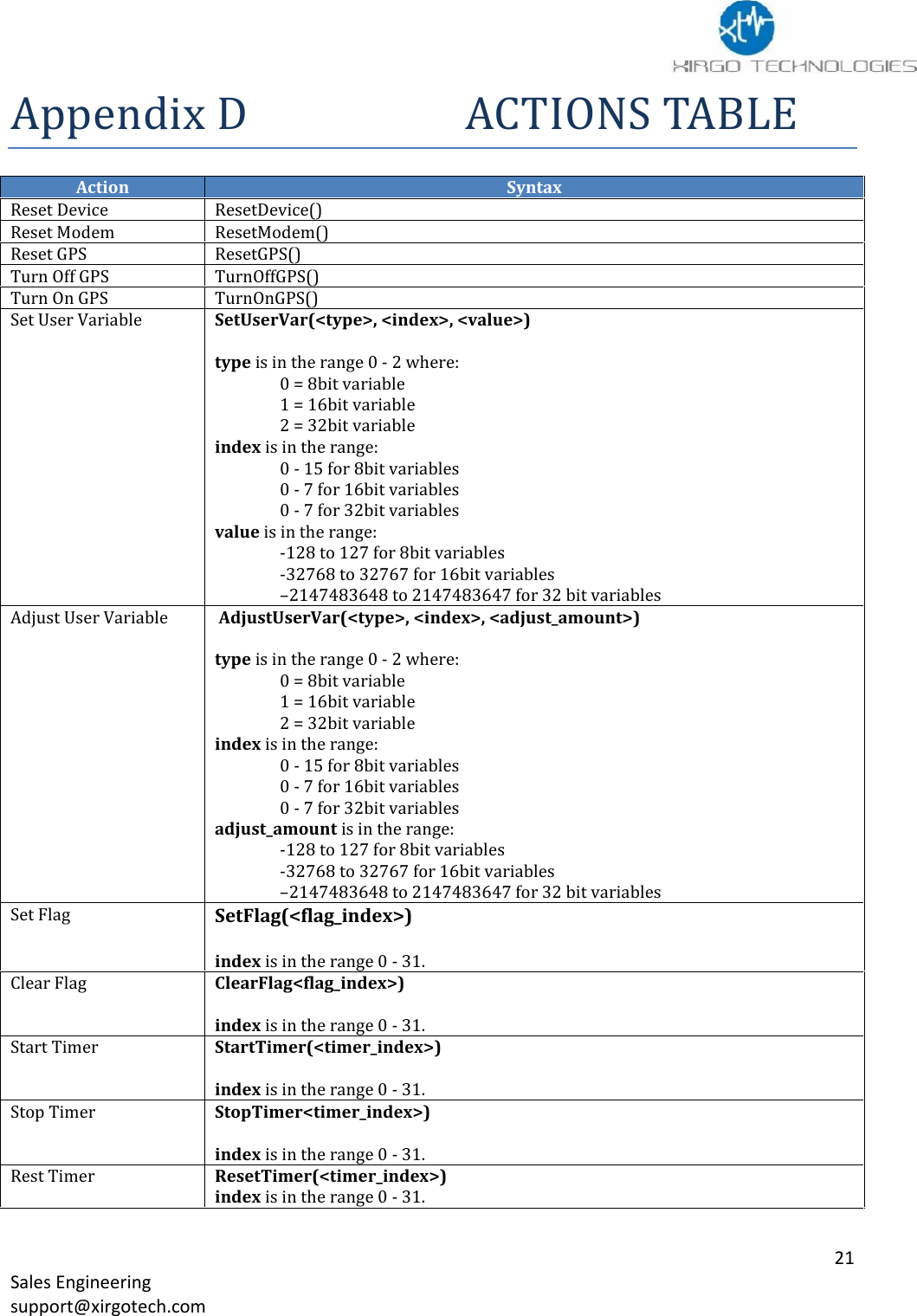
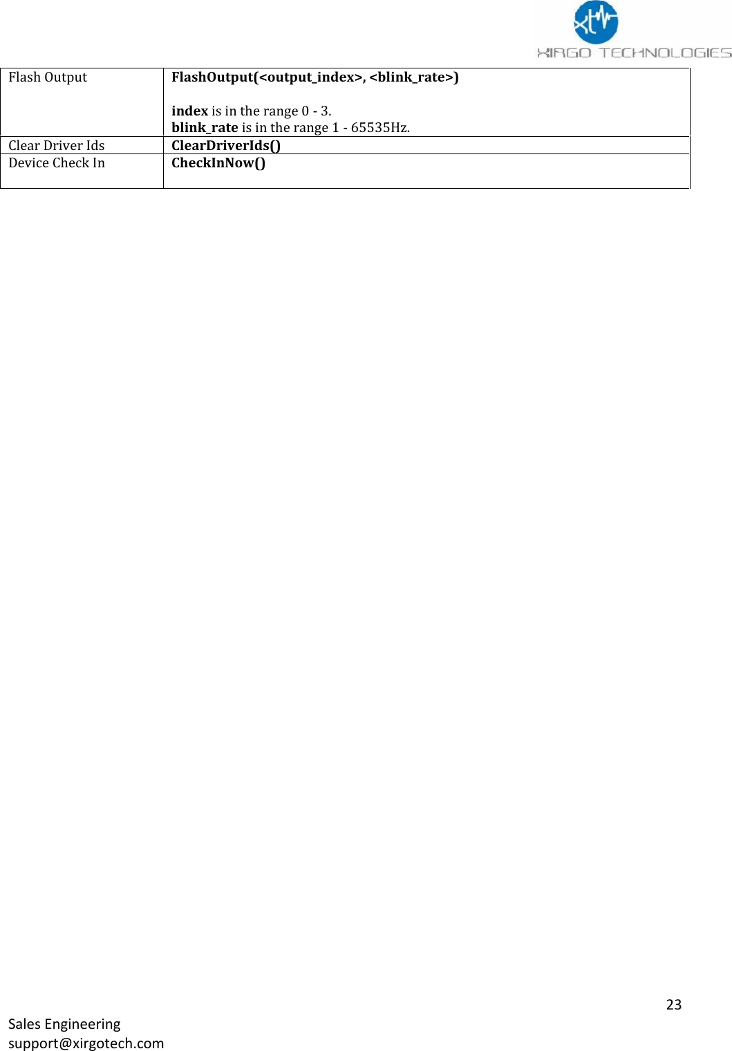
![22Sales Engineeringsupport@xirgotech.comACTIONSYNTAXBuild And Send Msg<packet_id>, <reason_code>, <destination_id>, <ack>)packet_id is in the range 0 – 255.reason_code is in the range 0 - 255.destination_id is in the range 0 - 9. One of the destinations servers dst[x]ack is in the range 0 - 10 = No Acknowledgement needed1 = Resend until acknowledgedClear LogTBDEnter Deep SleepEnterDeepSleep(<wake_mask>, <wake_minutes>)wake_mask is in the range 0x00 - 0xFF where:0x01 = Wake on Wired Ignition0x02 = Wake on Input 10x04 = Wake on Input 20x08 = Wake on Input 30x10 = Wake on Input 40x20 = Wake after wake_minutes0x40 = Wake on vibration detected0x80 = Wake on supply voltage > 13.2VEnter SleepEnterSleep(<wake_mask>, <wake_minutes>wake_mask is in the range 0x00 - 0xFF where:0x00 = Wake on SMS or UDP message received0x01 = Wake on Wired Ignition0x02 = Wake on Input 10x04 = Wake on Input 20x08 = Wake on Input 30x10 = Wake on Input 40x20 = Wake after wake_minutes0x40 = Wake on vibration detected0x80 = Wake on supply voltage > 13.2VSet Garmin PowerSetGarminPower(<power_state>)power_state is in the range 0 - 1 where:0 = Off1 = OnSend Garmin MsgTBDClear Trip OdomClearTripOdom(<odom_index>)index is in the range 0 - 1.Set OutputSetOutput(<output_index>)index is in the range 0 - 3Clear OutputClearOutput(<output_index>)index is in the range 0 - 3.Pulse OutputPulseOutput(<output_index>, <seconds_on>)index is in the range 0 - 3.seconds_on is in the range 1 - 65535.](https://usermanual.wiki/Xirgo-Technologies/XT6360/User-Guide-2621508-Page-23.png)