Xirgo Technologies XT6372R Vehicle GPS/Cellular Tracking Device with BT User Manual XT6372R User Guide
Xirgo Technologies Inc. Vehicle GPS/Cellular Tracking Device with BT XT6372R User Guide
UserManual.wiki
>
Xirgo Technologies
>
XT6372R User Manual
>
User manual
Contents
1.
User manual
2.
Users Manual
User manual
Navigation menu
Upload a User Manual
Namespaces
Wiki Guide
HTML
PDF
Info
Views
User Manual
Discussion / Help
Navigation
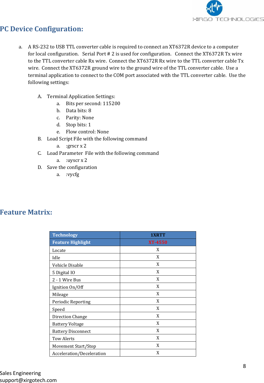
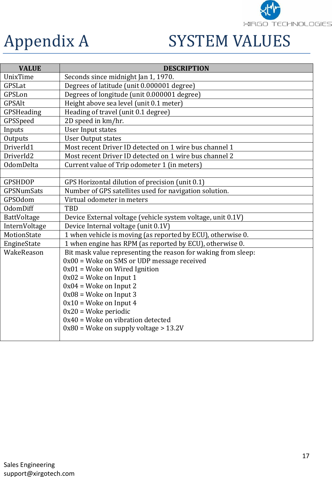
![9 Sales Engineering support@xirgotech.com Device Configuration The XT6372R is a full-feature device based on a platform that allows rapid customization by market and application requirements. The XT6372R series offers highly configurable firmware which allows full control of device reporting behavior. The customizable messages provides only the data required to support unique and evolving business needs. The XT6372R configuration is accomplished by loading 2 files: Script File Parameter File The Script File is the file that triggers the alerts and actions of the XT6372R. The Parameter File specifies values used to configure hardware peripherals, network behavior, and inputs to core functionality of the XT6372R. Script File A Script file can contain an unlimited number of Triggers. When scripting the Triggers are group into individual Trigger blocks. A trigger block is comprised of the following sections: Trigger Conditional Actions - optional Actions EXAMPLE: trigger when Eq(InputState(0), 1) [Debounce(0, 0)] condact always actions run BuildAndSendMsg(0, 2, 0, 0) DESCRIPTION: When ignition goes high a message is sent to the server. Park Time X Virtual Odometer X Quick Fence X Device Diagnostics X Motion X Accelerometer X Geo-Zones 50 Circular Back Up Battery 250mAh Communication Protocol TCP, UDP , UDPwACK Firmware Download FTP](https://usermanual.wiki/Xirgo-Technologies/XT6372R.User-manual/User-Guide-3483049-Page-10.png)
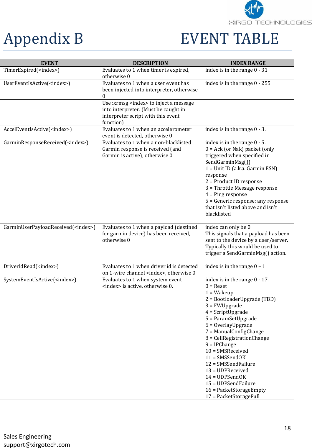
![10 Sales Engineering support@xirgotech.com Important notes on Scripting: 1. Each Trigger Block has one Trigger. 2. The Trigger must test true for an action to occur. 3. A test is usually made of one comparison. See Comparison table. 4. Each Trigger Block can contain unlimited Conditional Action Blocks. 5. Trigger Blocks and Conditional Action block will use the following when building a script: a. System Values b. Events c. Special Functions d. Numbers 6. Each Conditional Action Block may optionally contain one Conditional Action Block Test. 7. A Conditional Action Block Test may contain up to 5 comparisons (Using same “any” or “all” logic as described for Trigger Block Test). 8. Each Conditional Action Block must contain one Action Block. How Trigger Block Tests Work Each Trigger Block is entered when the Trigger Block Test becomes true. Note that the Trigger Block is NOT entered WHILE the Test IS true, only the moment it becomes true. For example if you want to trigger actions when vehicle speed goes above 80 km/hr: trigger when Gt(GPSSpeed, 80) [Debounce(0, 0)] The interpreter will enter the trigger block at the moment the vehicle speed increases above 80 km/hr. It will not continue to enter the trigger block during subsequent evaluations where the speed remains above 80 km/hr. Once the speed drops below 80 (for at least one evaluation), then the trigger block will be entered again next time the speed increases above 80 km/hr. Note that if the speed oscillates between 80.0 and 80.1 km/hr it is possible to cause the actions to be executed as frequently as the speed oscillates. In order to avoid this, make use of the debounce specifiers. How Conditional Action Block Tests Work Unlike Trigger Block Tests, Conditional Action Block Tests allow the action to be performed WHILE the test is true. Continuing with the example above, let's say we want to further limit our actions to only execute the moment speed goes above 80 km/hr AND only when the vehicle heading is within 10 degrees of North: trigger when Gt(GPSSpeed, 80) [Debounce(0, 0)] condact any InRange(GPSHeading, 3500, 3600) [Debounce(0, 0)] InRange(GPSHeading, 0, 100) [Debounce(0, 0)] actions All Conditional Action blocks are independent. One is not dependent on the other. Condact Always This means the actions inside a Conditional Action Block will ALWAYS run when the trigger Block's test(s) are true. Condact When When only one comparison is used Condact Any The test is true when ANY of the comparisons is true. Condact All - ALL comparisons must be true for test to be true.](https://usermanual.wiki/Xirgo-Technologies/XT6372R.User-manual/User-Guide-3483049-Page-11.png)
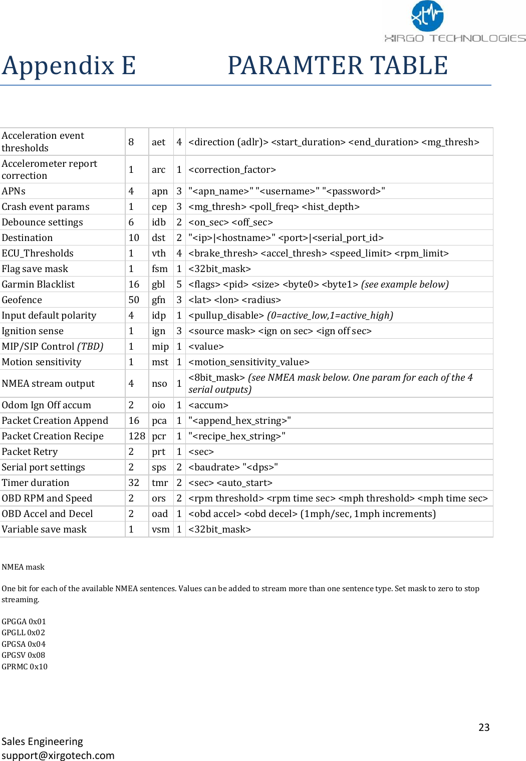
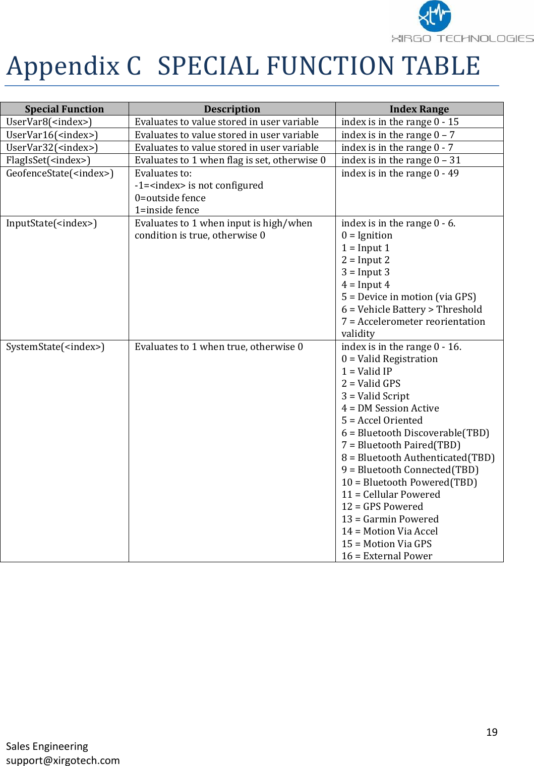
![12 Sales Engineering support@xirgotech.com Parameter File The parameter file is the setting for all of the XT6372R hardware peripherals, network behavior, and inputs to core functionality of the XT6372R. The following table contains all the parameters that can be configured in a XT6372R: Acceleration event thresholds Accelerometer report correction APNs (GSM only) Crash event params Debounce settings Destination ECU_Thresholds Flag save mask Garmin Blacklist Geofence Input default polarity Ignition sense MIP/SIP Control (TBD) Motion sensitivity NMEA stream output Odom Ign Off accum Packet Creation Append Packet Creation Recipe Packet Retry Serial port settings Timer duration OBD RPM and Speed OBD Accel and Decel Variable save mask See Appendix C for Parameter settings. Creating a Parameter File: 1. The parameter settings are written and saved as a .txt file. 2. Use :wycfg in front of the parameter your are configuring. 3. To load the parameter file you can use XDMI or load the file over Serial Port 2. a. Load via Serial port use the following commands i. :uyscr x 2 load the file ii. :vycfg Save the parameter file Below is an example of a parameter file. :wycfg pdo 0 1 :wycfg dst[0] "71.24.53.116" 65534 :wycfg dst[9] "none" 65535 :wycfg pcr[0] "00080104030607080b17" :wycfg pcr[1] "01050103070809" :wycfg pcr[2] "02140104535455565758595a5b5c5d5e5f6061622c2e" :wycfg pcr[3] "030701040305060708" :wycfg pcr[4] "040701040305060708" :wycfg pcr[5] "050701040305060708" :wycfg pcr[6] "06080104030607080b17" :wycfg pcr[7] "07080104030607080b17 :wycfg pcr[8] "08040104060c" :wycfg tmr[0] 90 1 :wycfg tmr[1] 90 1 :wycfg aet[0] 0 1000 1000 205](https://usermanual.wiki/Xirgo-Technologies/XT6372R.User-manual/User-Guide-3483049-Page-13.png)
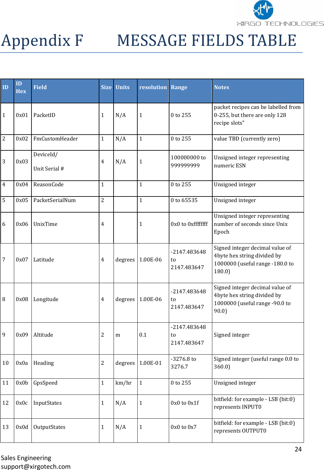
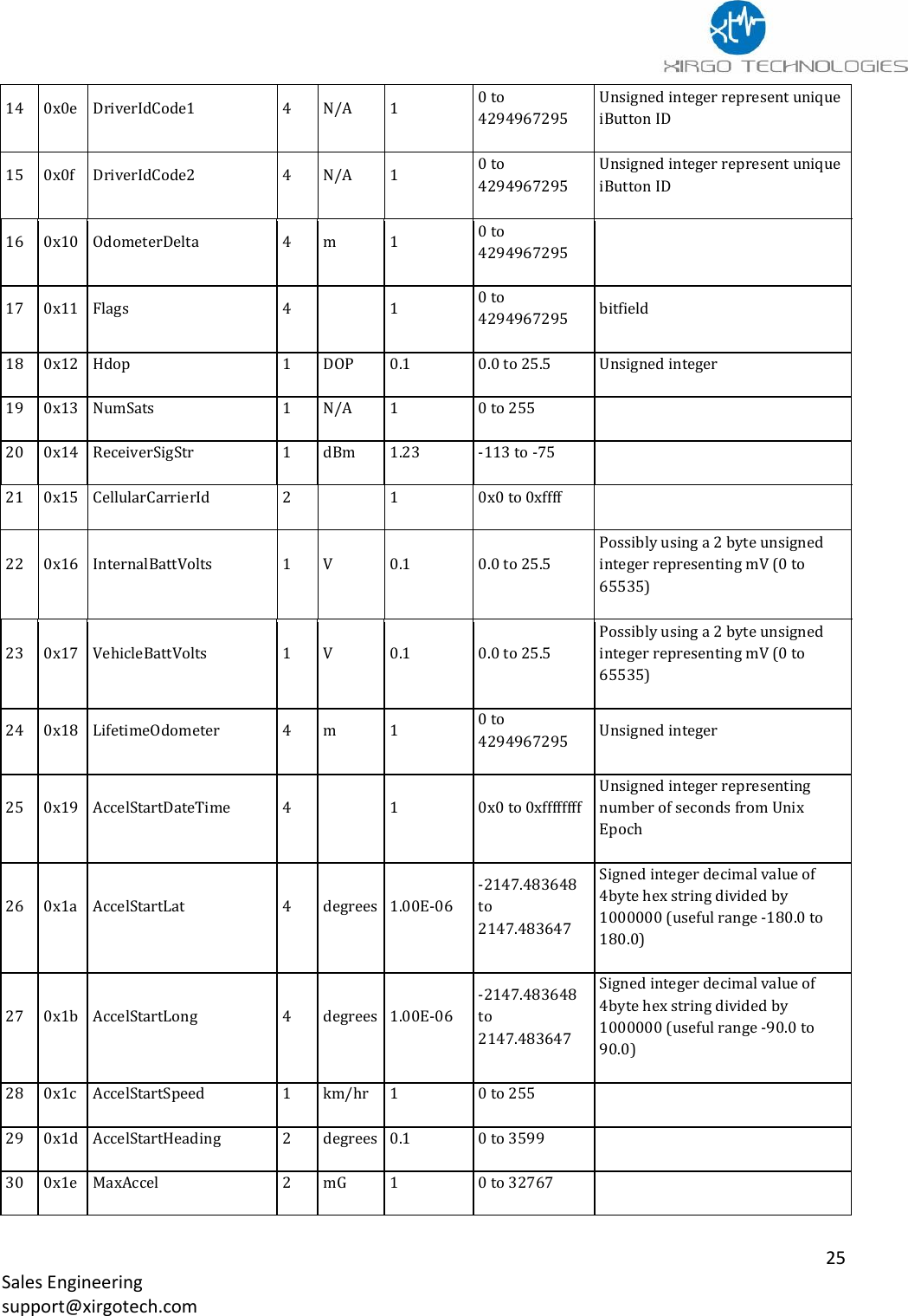
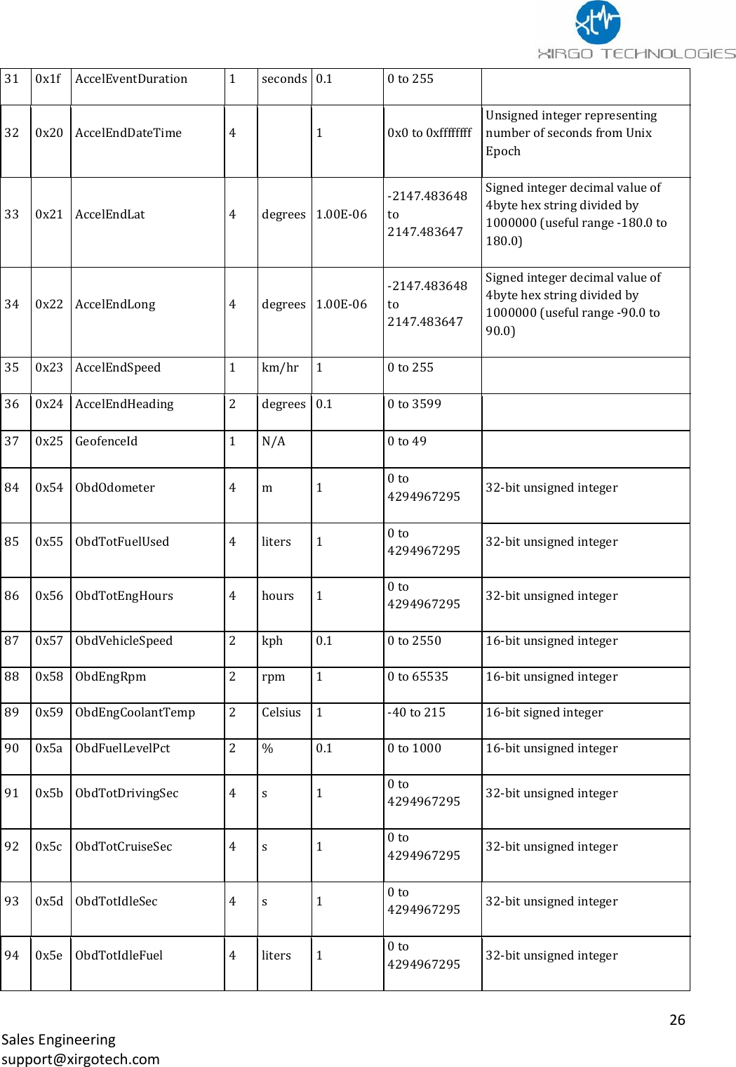
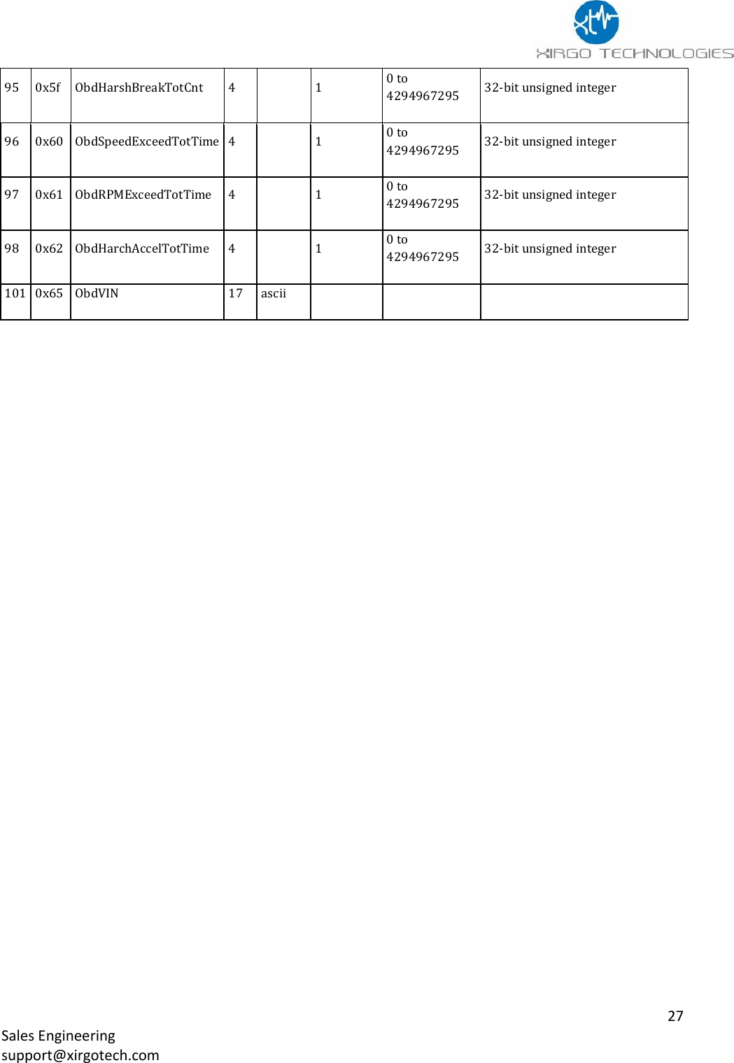
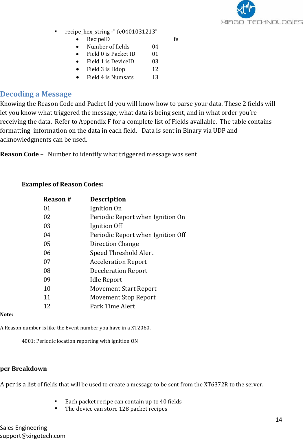
![13 Sales Engineering support@xirgotech.com Messages How to create a Message The XT6372R custom message allows users to select what fields of data to be sent in a message when triggered. A message can contain up to 40 data fields and you can have up to 128 different messages. Refer to Appendix F - Message Field Table When defining a Message use the following syntax: pcr[<slot_index>] "<recipe_hex_string>" • where: o <slot_index> is in the range 0 - 127 o "<recipe_hex_string>" is a quoted string of hexadecimal bytes (represented by two ascii characters) The Message Field Table in Appendix F contains the Hex values for the individual fields that can be selected to create the Packet. ▪ String format: "<recipe_id><num_fields><field_0><field_1>...<field_N>" EXAMPLES • pcr[0] "0003010306" o pcr slot 0 will contain a Recipe string with 3 fields: PacketID, DeviceID, and GpsSpeed ▪ recipe_hex_string -"000301030b" ▪ RecipeID 00 (Hex) ▪ Number of fields 03 (Hex) ▪ Field 0 is Packet ID 01 (Hex) ▪ Field 1 is DeviceID 03 (Hex) ▪ Field 2 is GpsSpeed 0b (Hex) Notes: o The device can store and use 128 pcr (messages) • :wycfg pcr[0] …. :wycfg pcr[127] • RecipeID is always in Hex. • pcr[1] "14050103070809" o pcr slot 1 will contain a Recipe string with 5 fields : PacketID, DeviceID, Latitude, Longitude, and Altitude ▪ recipe_hex_string -"14050103070809" • RecipeID 01 • Number of fields 05 • Field 0 is Packet ID 01 • Field 1 is DeviceID 03 • Field 2 is Latitude 07 • Field 3 is Longitude 08 • Field 4 is Altitude 09 :wycfg pcr[254] "fe0401031213" o PCR slot 2 will contain a Recipe string with 4 fields: PacketID, DeviceID, Hdop, and NumSats](https://usermanual.wiki/Xirgo-Technologies/XT6372R.User-manual/User-Guide-3483049-Page-14.png)
![15 Sales Engineering support@xirgotech.com pcr[<slot_index>] "<recipe_hex_string>" <slot_index> is in the range 0 - 127 "<recipe_hex_string>" is a quoted string of hexadecimal bytes (represented by two ascii characters) String format: "<packet_id><num_fields><field_0><field_1>...<field_N>" Example: pcr 1 will contain a 5 fields : PacketID, DeviceID, Latitude, Longitude, and Altitude pcr[1] "01050103070809" RecipeID 01 Number of fields 05 Field 0 is Packet ID 01 Field 1 is DeviceID 03 Field 2 is Latitude 07 Field 3 is Longitude 08 Field 4 is Altitude 09 Below is an example of a packet recipe that is partially decoded. EXAMPLE: pcr[1] "010E01040305060708090a0b12131415" (all values below are in Hex) Recipe ID 01 Number of fields 0E Field HEX ID Value Parsed Comment PacketID 01 01 01 ReasonCode 04 03 03 (IGN. OFF MESSAGE) Serial # 03 088c1c72 143400050 Unit Serial Number PacketSerialNum 05 205a 8282 Etc.. DATA FROM DEVICE CONVERTED FROM BINARY TO HEX USED IN TABLE ABOVE datagram: 4 from 75.255.159.0:3000 (size: 31 bytes) HEX--------------------------------------------------------------------------- 01 03 08 8c 1c 72 20 5a 54 81 be e1 01 f7 fb dd fa 3a 18 7a 07 0c 0a 1e 01 1c 04 00 15 ff ff ------------------------------------------------------------------------------](https://usermanual.wiki/Xirgo-Technologies/XT6372R.User-manual/User-Guide-3483049-Page-16.png)
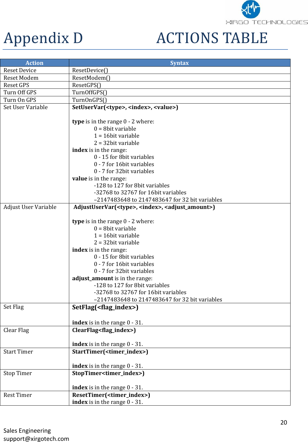
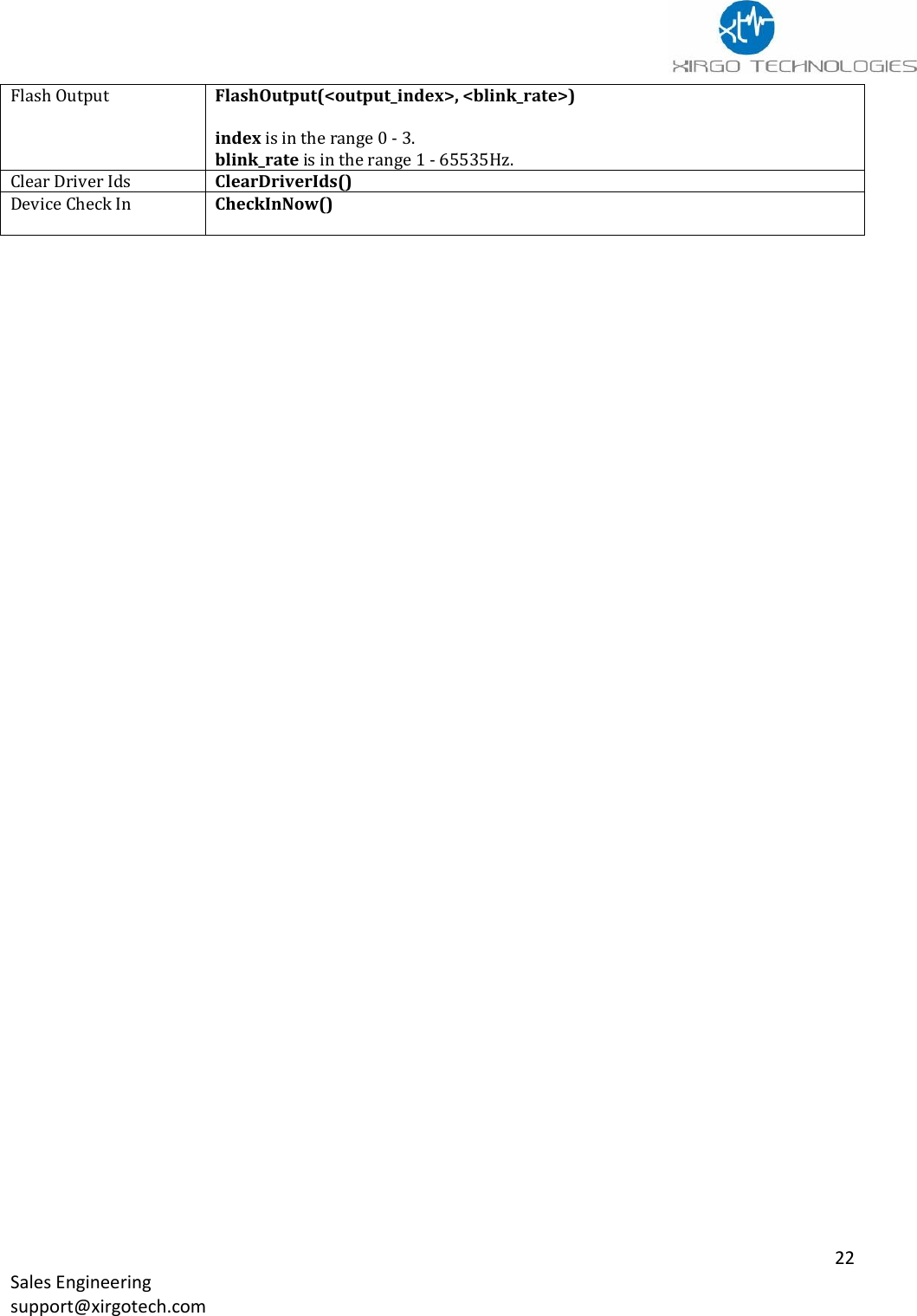
![21 Sales Engineering support@xirgotech.com ACTION SYNTAX Build And Send Msg <packet_id>, <reason_code>, <destination_id>, <ack>) packet_id is in the range 0 – 255. reason_code is in the range 0 - 255. destination_id is in the range 0 - 9. One of the destinations servers dst[x] ack is in the range 0 - 1 0 = No Acknowledgement needed 1 = Resend until acknowledged Clear Log TBD Enter Deep Sleep EnterDeepSleep(<wake_mask>, <wake_minutes>) wake_mask is in the range 0x00 - 0xFF where: 0x01 = Wake on Wired Ignition 0x02 = Wake on Input 1 0x04 = Wake on Input 2 0x08 = Wake on Input 3 0x10 = Wake on Input 4 0x20 = Wake after wake_minutes 0x40 = Wake on vibration detected 0x80 = Wake on supply voltage > 13.2V Enter Sleep EnterSleep(<wake_mask>, <wake_minutes> wake_mask is in the range 0x00 - 0xFF where: 0x00 = Wake on SMS or UDP message received 0x01 = Wake on Wired Ignition 0x02 = Wake on Input 1 0x04 = Wake on Input 2 0x08 = Wake on Input 3 0x10 = Wake on Input 4 0x20 = Wake after wake_minutes 0x40 = Wake on vibration detected 0x80 = Wake on supply voltage > 13.2V Set Garmin Power SetGarminPower(<power_state>) power_state is in the range 0 - 1 where: 0 = Off 1 = On Send Garmin Msg TBD Clear Trip Odom ClearTripOdom(<odom_index>) index is in the range 0 - 1. Set Output SetOutput(<output_index>) index is in the range 0 - 3 Clear Output ClearOutput(<output_index>) index is in the range 0 - 3. Pulse Output PulseOutput(<output_index>, <seconds_on>) index is in the range 0 - 3. seconds_on is in the range 1 - 65535.](https://usermanual.wiki/Xirgo-Technologies/XT6372R.User-manual/User-Guide-3483049-Page-22.png)