Xirgo Technologies XT6372R Vehicle GPS/Cellular Tracking Device with BT User Manual XT6372R User Guide
Xirgo Technologies Inc. Vehicle GPS/Cellular Tracking Device with BT XT6372R User Guide
Contents
- 1. User manual
- 2. Users Manual
User manual

1
Sales Engineering
support@xirgotech.com
Contents
Document Change History .......................................................................................................................... 2
Hardware Specification:.............................................................................................................................. 3
Connectors IO Interface: ............................................................................................................................. 4
Cable Harness Specification: ...................................................................................................................... 6
LED Definition ............................................................................................................................................. 7
Current Consumption ................................................................................................................................. 7
Device Mounting: ......................................................................................................................................... 7
PC Device Configuration: ............................................................................................................................ 8
Feature Matrix: ............................................................................................................................................ 8
Device Configuration ................................................................................................................................... 9
Script File ................................................................................................................................................. 9
Parameter File ....................................................................................................................................... 12
Messages .................................................................................................................................................... 13
How to create a Message....................................................................................................................... 13
Decoding a Message .............................................................................................................................. 14
Acknowledgements ............................................................................................................................... 16
Regulatory Statements: .............................................................................................................................. 28
2
Sales Engineering
support@xirgotech.com
Document Change History
Revision
Date
Changes
1.0
4/12/2017
Initial Release based on XT6350 User Guide_V2
2.0
7/21/2017
Revised based on TCB notes
3
Sales Engineering
support@xirgotech.com
Hardware Specification:
Cellular Wireless Technology:
Verizon LTE: Bands 4 and 13 (1700/2100 AWS, 700 MHz) - Models: XT6372R
Parameter
Spec
GPS Specification
Receiver
72 channels
Receiver tracking
sensitivity
-165 dBm
CEP Accuracy
+/- 2.5m
TTFF
- Cold Start
- Hot Start
<27 sec
< 1 sec
HW Options:
3-axis Accel.
BT/BTLE
Last Gasp Back-up
Battery
Internal 250 mAh rechargeable Li-
Ion
Power Requirements
D.C. Power
9-32V
Physical Connection
Data Connector
24-pin Molex Main
14-pin Molex OBD/J-Bus
Antenna:
Cellular/GPS /BT
Internal
SIM Access (2G/3G)
N/A
Programming
Serial
Xirgo Device Manager (XDMI)
Mechanical
Case Material
PC2407, Black
Dimension
3.35”x 3.1”x 0.8”
Weight
3 oz.
Operating
Temperature
-30C to +75C
Certifications
Product
FCC ID: GKM-XT6372R
IC: 10281A-XT6372R
Carrier
Verizon
Notes:
TTTF: All satellites at -130 dBm ; Accuracy: CEP, 50%, 24 hours static, -130 dBm, > 6 SVs

4
Sales Engineering
support@xirgotech.com
Connectors IO Interface:
Main 24-pin Molex Connector (IO Interface):
Pin No.
Pin Name
Comments
1
12/24 Volt Power
2
LED+12V
w/5K limiting resistor (panic LED)
3
Ground
Main Battery GND
4
Ign Out
Buzzer +12V/24V with 560 ohm
5
IN0
Ignition Sense
6
IN1
7
IN2
8
IN3
Panic: pin3 on panic 4-pin Molex
9
IN4
10
OUT0
Buzzer GND
11
OUT1
12
OUT2
Panic: pin4 (LED) on panic 4-pin
Molex
13
Garmin PWR
12V/2A Switched
14
Serial Port-1 TX
Garmin FMI Tx
15
Serial Port-1 RX
Garmin FMI Rx
16
Serial Port-1 GND
Garmin FMI GND
17
Serial Port-2 TX
18
Serial Port-2 RX
19
Serial Port-2 GND
20
1-Wire Serial Main
iButton Data (default)
21
1-Wire Serial Sec.
22
Ext. ADC
23
Spare GND
Panic GND
24
Spare GND
5
Sales Engineering
support@xirgotech.com
OBD 14-pin Molex connector (OBD2/JBUS/SWC):
J1962 OBD2
Pin No.
XT6372R
Pins
XT6372R Pin Description
9 Pin J-Bus
6 Pin J-Bus
6
1
CAN_HS_H
C
2
J1708_RXD
G
B
3
J1708_TXD
F
A
15
4
L_LINE
10
5
J1850_NEG
2
6
J1850_POS
7
14
8
CAN_HS_L
D
3
9
CAN_MS_H
11
10
CAN_MS_L
1
11
SWC_BUS
7
12
K_LINE
5&4
13
GND
A
E
16
14
Vehicle Power (VBAT)
B
C

6
Sales Engineering
support@xirgotech.com
Cable Harness Specification:
• 24-pin Microfit: Molex 43025-2400
• Panic SW/LED Button Conn. Molex 43020-0401 (4 pin 2 row female shell)
• I-Button Conn.: Molex 43640-0201 (2 pin Female Shell)
• Buzzer Conn.: Molex 43640-0301 (3 pin Female Shell)
• Garmin Conn. Molex 43020-1001 (10 pin 2 row female shell)
• Garmin pins 2 and 4 looped-in (black wire, 26 AWG)
• Molex male pins: 43031-0002
• Total length: 5 ft.
• Pins 1, 3, and 5 are 18 AWG, All others are 24 AWG.
• Fuse: 3A in line with pins with pins 1 (red) and 5 (white), 7 in. from wire end
• Wires 1, 3, and 5 to be jacketed up to the fuse
24-pin
No.
Color
Length
AWG
Pin function
Comments
I-Button
Buzz.
Panic SW
LED
Garmin
1
Red
60 in.
18
VBAT
3A fuse, 7 in. from end
2
Orange
7 in.
20
LED+12V
3
3
Black
60 in.
18
Ground
4
White
7 in.
20
Ign Out
1
5
White
60 in.
18
IN0
3A fuse, 7 in. from end
6
Gray
60 in.
20
IN1
7
Brown
60 in.
20
IN2
8
Blue
7 in.
20
IN3
1
9
Red
60 in.
20
IN4
10
Brown
7 in.
20
OUT0
Buzzer GND
2
11
Orange
60 in.
20
OUT1
12
Yellow
7 in.
20
OUT2
4
13
Red
7 in.
20
Garmin PWR
12V/2A Switched
5
14
White/Brown
7 in.
20
Serial Port-1
TX
Garmin FMI Tx
1
15
Green
7 in.
20
Serial Port-1
RX
Garmin FMI Rx
6
16
Orange/Brown
7 in.
20
Serial Port-1
GND
Garmin FMI GND
4
17
Yellow
7 in.
20
Serial Port-2
TX
18
Green
7 in.
20
Serial Port-2
RX
19
Black
7 in.
20
Serial Port-2
GND
20
Gray
7 in.
20
1-Wire Serial
Main
i-Button
1

7
Sales Engineering
support@xirgotech.com
21
White
60 in.
20
OWB2
22
Purple
60 in.
20
Ext. ADC
23
Black
7 in.
20
Spare GND
Panic GND
2
24
Blue/Green
7 in.
20
Spare GND
2
LED Definition
Current Consumption
OPERATING MODE
CURRENT CONSUMPTION
Deep Sleep (non-functional mode)
5 mA
Standby
15 mA
Active Receive
70 mA
Device Mounting:
The XT6372R device must be securely installed. The accelerometer will not calibrate if unit is loose
when vehicle is in motion. When mounting the device, use a tie strap to secure the device as noted
below.
BASE
UNIT
LED
Description
Status
Cellular (Amber)
Searching for Cellular Network
LED OFF
Cellular Carrier Lock
Solid
GPS (Green)
Searching for satellite
Solid
GPS Lock
Blinking
Optional
Bluetooth (Blue)
TBD
TBD

8
Sales Engineering
support@xirgotech.com
PC Device Configuration:
a. A RS-232 to USB TTL converter cable is required to connect an XT6372R device to a computer
for local configuration. Serial Port # 2 is used for configuration. Connect the XT6372R Tx wire
to the TTL converter cable Rx wire. Connect the XT6372R Rx wire to the TTL converter cable Tx
wire. Connect the XT6372R ground wire to the ground wire of the TTL converter cable. Use a
terminal application to connect to the COM port associated with the TTL converter cable. Use the
following settings:
A. Terminal Application Settings:
a. Bits per second: 115200
b. Data bits: 8
c. Parity: None
d. Stop bits: 1
e. Flow control: None
B. Load Script File with the following command
a. :grscr x 2
C. Load Parameter File with the following command
a. :uyscr x 2
D. Save the configuration
a. :vycfg
Feature Matrix:
Technology
1XRTT
Feature Highlight
XT-4550
Locate
X
Idle
X
Vehicle Disable
X
5 Digital IO
X
2 - 1 Wire Bus
X
Ignition On/Off
X
Mileage
X
Periodic Reporting
X
Speed
X
Direction Change
X
Battery Voltage
X
Battery Disconnect
X
Tow Alerts
X
Movement Start/Stop
X
Acceleration/Deceleration
X

9
Sales Engineering
support@xirgotech.com
Device Configuration
The XT6372R is a full-feature device based on a platform that allows rapid customization by market and
application requirements. The XT6372R series offers highly configurable firmware which allows full control
of device reporting behavior. The customizable messages provides only the data required to support unique
and evolving business needs. The XT6372R configuration is accomplished by loading 2 files:
Script File
Parameter File
The Script File is the file that triggers the alerts and actions of the XT6372R.
The Parameter File specifies values used to configure hardware peripherals, network behavior, and inputs
to core functionality of the XT6372R.
Script File
A Script file can contain an unlimited number of Triggers. When scripting the Triggers are group
into individual Trigger blocks. A trigger block is comprised of the following sections:
Trigger
Conditional Actions - optional
Actions
EXAMPLE:
trigger when Eq(InputState(0), 1) [Debounce(0, 0)]
condact always
actions
run BuildAndSendMsg(0, 2, 0, 0)
DESCRIPTION:
When ignition goes high a message is sent to the server.
Park Time
X
Virtual Odometer
X
Quick Fence
X
Device Diagnostics
X
Motion
X
Accelerometer
X
Geo-Zones
50 Circular
Back Up Battery
250mAh
Communication Protocol
TCP, UDP , UDPwACK
Firmware Download
FTP

10
Sales Engineering
support@xirgotech.com
Important notes on Scripting:
1. Each Trigger Block has one Trigger.
2. The Trigger must test true for an action to occur.
3. A test is usually made of one comparison. See Comparison table.
4. Each Trigger Block can contain unlimited Conditional Action Blocks.
5. Trigger Blocks and Conditional Action block will use the following when building a script:
a. System Values
b. Events
c. Special Functions
d. Numbers
6. Each Conditional Action Block may optionally contain one Conditional Action Block Test.
7. A Conditional Action Block Test may contain up to 5 comparisons (Using same “any” or “all” logic as described
for Trigger Block Test).
8. Each Conditional Action Block must contain one Action Block.
How Trigger Block Tests Work
Each Trigger Block is entered when the Trigger Block Test becomes true. Note that the Trigger Block is NOT
entered WHILE the Test IS true, only the moment it becomes true. For example if you want to trigger actions
when vehicle speed goes above 80 km/hr:
trigger when Gt(GPSSpeed, 80) [Debounce(0, 0)]
The interpreter will enter the trigger block at the moment the vehicle speed increases above 80 km/hr. It will
not continue to enter the trigger block during subsequent evaluations where the speed remains above 80
km/hr. Once the speed drops below 80 (for at least one evaluation), then the trigger block will be entered
again next time the speed increases above 80 km/hr.
Note that if the speed oscillates between 80.0 and 80.1 km/hr it is possible to cause the actions to be executed as
frequently as the speed oscillates. In order to avoid this, make use of the debounce specifiers.
How Conditional Action Block Tests Work
Unlike Trigger Block Tests, Conditional Action Block Tests allow the action to be performed WHILE the test is
true. Continuing with the example above, let's say we want to further limit our actions to only execute the
moment speed goes above 80 km/hr AND only when the vehicle heading is within 10 degrees of North:
trigger when Gt(GPSSpeed, 80) [Debounce(0, 0)]
condact any InRange(GPSHeading, 3500, 3600) [Debounce(0, 0)]
InRange(GPSHeading, 0, 100) [Debounce(0, 0)]
actions
All Conditional Action blocks are independent. One is not dependent on the other.
Condact Always This means the actions inside a Conditional Action Block will ALWAYS run when the
trigger Block's test(s) are true.
Condact When When only one comparison is used
Condact Any The test is true when ANY of the comparisons is true.
Condact All - ALL comparisons must be true for test to be true.
11
Sales Engineering
support@xirgotech.com
COMPARISONS TABLE:
COMPARISON
DESCRIPTION
InRange(<a>, <b>, <c>)
True when argument a is between argument b and argument c (inclusive)
NotInRange(<a>, <b>, <c>)
True when a is less than b or a is greater than c. b must be less than c.
Eq(<a>, <b>)
True when a equals b.
NotEq(<a>, <b>)
True when a is not equal to b.
Gt(<a>, <b>)
True when a is greater than b.
Lt(<a>, <b>)
True when a is less than b.
GtEq(<a>, <b>)
True when a is greater than/equal to b.
LtEq(<a>, <b>)
True when a is less than/equal to b.
Test items (<a>, <b>, <c> above) should be one of:
System Value
Event
Special Function
Numbers (constants)
Note:
See Appendices for Complete Tables
Debounce
Debounce(<hi>, <lo>) - where hi and lo are specified in seconds (max: 15). The 'Debounce Specify' is only
used following certain tests (see below). When a debounce is specified, it means that a test is true only AFTER
the comparison is true for hi seconds, and it is false only AFTER the comparison is false for lo seconds.
A test debounce MUST be specified any time the first argument in the test is either:
System value
Special function.
12
Sales Engineering
support@xirgotech.com
Parameter File
The parameter file is the setting for all of the XT6372R hardware peripherals, network behavior, and
inputs to core functionality of the XT6372R. The following table contains all the parameters that can
be configured in a XT6372R:
Acceleration event
thresholds
Accelerometer report
correction
APNs (GSM only)
Crash event params
Debounce settings
Destination
ECU_Thresholds
Flag save mask
Garmin Blacklist
Geofence
Input default polarity
Ignition sense
MIP/SIP Control (TBD)
Motion sensitivity
NMEA stream output
Odom Ign Off accum
Packet Creation Append
Packet Creation Recipe
Packet Retry
Serial port settings
Timer duration
OBD RPM and Speed
OBD Accel and Decel
Variable save mask
See Appendix C for Parameter settings.
Creating a Parameter File:
1. The parameter settings are written and saved as a .txt file.
2. Use :wycfg in front of the parameter your are configuring.
3. To load the parameter file you can use XDMI or load the file over Serial Port 2.
a. Load via Serial port use the following commands
i. :uyscr x 2 load the file
ii. :vycfg Save the parameter file
Below is an example of a parameter file.
:wycfg pdo 0 1
:wycfg dst[0] "71.24.53.116" 65534
:wycfg dst[9] "none" 65535
:wycfg pcr[0] "00080104030607080b17"
:wycfg pcr[1] "01050103070809"
:wycfg pcr[2] "02140104535455565758595a5b5c5d5e5f6061622c2e"
:wycfg pcr[3] "030701040305060708"
:wycfg pcr[4] "040701040305060708"
:wycfg pcr[5] "050701040305060708"
:wycfg pcr[6] "06080104030607080b17"
:wycfg pcr[7] "07080104030607080b17
:wycfg pcr[8] "08040104060c"
:wycfg tmr[0] 90 1
:wycfg tmr[1] 90 1
:wycfg aet[0] 0 1000 1000 205

13
Sales Engineering
support@xirgotech.com
Messages
How to create a Message
The XT6372R custom message allows users to select what fields of data to be sent in a message when
triggered. A message can contain up to 40 data fields and you can have up to 128 different messages.
Refer to Appendix F - Message Field Table
When defining a Message use the following syntax:
pcr[<slot_index>] "<recipe_hex_string>"
• where:
o <slot_index> is in the range 0 - 127
o "<recipe_hex_string>" is a quoted string of hexadecimal bytes (represented by two ascii
characters) The Message Field Table in Appendix F contains the Hex values for the
individual fields that can be selected to create the Packet.
▪ String format: "<recipe_id><num_fields><field_0><field_1>...<field_N>"
EXAMPLES
• pcr[0] "0003010306"
o pcr slot 0 will contain a Recipe string with 3 fields: PacketID, DeviceID, and GpsSpeed
▪ recipe_hex_string -"000301030b"
▪ RecipeID 00 (Hex)
▪ Number of fields 03 (Hex)
▪ Field 0 is Packet ID 01 (Hex)
▪ Field 1 is DeviceID 03 (Hex)
▪ Field 2 is GpsSpeed 0b (Hex)
Notes:
o The device can store and use 128 pcr (messages)
• :wycfg pcr[0] …. :wycfg pcr[127]
• RecipeID is always in Hex.
• pcr[1] "14050103070809"
o pcr slot 1 will contain a Recipe string with 5 fields : PacketID, DeviceID, Latitude, Longitude,
and Altitude
▪ recipe_hex_string -"14050103070809"
• RecipeID 01
• Number of fields 05
• Field 0 is Packet ID 01
• Field 1 is DeviceID 03
• Field 2 is Latitude 07
• Field 3 is Longitude 08
• Field 4 is Altitude 09
:wycfg pcr[254] "fe0401031213"
o PCR slot 2 will contain a Recipe string with 4 fields: PacketID, DeviceID, Hdop, and NumSats

14
Sales Engineering
support@xirgotech.com
▪ recipe_hex_string -" fe0401031213"
• RecipeID fe
• Number of fields 04
• Field 0 is Packet ID 01
• Field 1 is DeviceID 03
• Field 3 is Hdop 12
• Field 4 is Numsats 13
Decoding a Message
Knowing the Reason Code and Packet Id you will know how to parse your data. These 2 fields will
let you know what triggered the message, what data is being sent, and in what order you’re
receiving the data. Refer to Appendix F for a complete list of Fields available. The table contains
formatting information on the data in each field. Data is sent in Binary via UDP and
acknowledgments can be used.
Reason Code – Number to identify what triggered message was sent
Examples of Reason Codes:
Reason # Description
01 Ignition On
02 Periodic Report when Ignition On
03 Ignition Off
04 Periodic Report when Ignition Off
05 Direction Change
06 Speed Threshold Alert
07 Acceleration Report
08 Deceleration Report
09 Idle Report
10 Movement Start Report
11 Movement Stop Report
12 Park Time Alert
Note:
A Reason number is like the Event number you have in a XT2060.
4001: Periodic location reporting with ignition ON
pcr Breakdown
A pcr is a list of fields that will be used to create a message to be sent from the XT6372R to the server.
▪ Each packet recipe can contain up to 40 fields
▪ The device can store 128 packet recipes
15
Sales Engineering
support@xirgotech.com
pcr[<slot_index>] "<recipe_hex_string>"
<slot_index> is in the range 0 - 127
"<recipe_hex_string>" is a quoted string of hexadecimal bytes (represented by two ascii characters)
String format: "<packet_id><num_fields><field_0><field_1>...<field_N>"
Example:
pcr 1 will contain a 5 fields : PacketID, DeviceID, Latitude, Longitude, and Altitude
pcr[1] "01050103070809"
RecipeID 01
Number of fields 05
Field 0 is Packet ID 01
Field 1 is DeviceID 03
Field 2 is Latitude 07
Field 3 is Longitude 08
Field 4 is Altitude 09
Below is an example of a packet recipe that is partially decoded.
EXAMPLE:
pcr[1] "010E01040305060708090a0b12131415"
(all values below are in Hex)
Recipe ID 01
Number of fields 0E
Field HEX ID Value Parsed Comment
PacketID 01 01 01
ReasonCode 04 03 03 (IGN. OFF MESSAGE)
Serial # 03 088c1c72 143400050 Unit Serial Number
PacketSerialNum 05 205a 8282
Etc..
DATA FROM DEVICE CONVERTED FROM BINARY TO HEX USED IN TABLE ABOVE
datagram: 4 from 75.255.159.0:3000 (size: 31 bytes)
HEX---------------------------------------------------------------------------
01 03 08 8c 1c 72 20 5a 54 81 be e1 01 f7 fb dd
fa 3a 18 7a 07 0c 0a 1e 01 1c 04 00 15 ff ff
------------------------------------------------------------------------------

16
Sales Engineering
support@xirgotech.com
Acknowledgements
Currently the XT6372R supports a simple acknowledgement consisting of four bytes (88-88-xx-xx)
where xx-xx is the packet serial number. You will want to send the 88-88 header and return the
serial number of the packet sent to you, in the third and fourth byte. Therefore, the XIRGO unit will
only accept an acknowledgement payload of 88-88-01-04 for a packet sent with packet serial
number 260 (hex 01-04).

17
Sales Engineering
support@xirgotech.com
Appendix A SYSTEM VALUES
VALUE
DESCRIPTION
UnixTime
Seconds since midnight Jan 1, 1970.
GPSLat
Degrees of latitude (unit 0.000001 degree)
GPSLon
Degrees of longitude (unit 0.000001 degree)
GPSAlt
Height above sea level (unit 0.1 meter)
GPSHeading
Heading of travel (unit 0.1 degree)
GPSSpeed
2D speed in km/hr.
Inputs
User Input states
Outputs
User Output states
DriverId1
Most recent Driver ID detected on 1 wire bus channel 1
DriverId2
Most recent Driver ID detected on 1 wire bus channel 2
OdomDelta
Current value of Trip odometer 1 (in meters)
GPSHDOP
GPS Horizontal dilution of precision (unit 0.1)
GPSNumSats
Number of GPS satellites used for navigation solution.
GPSOdom
Virtual odometer in meters
OdomDiff
TBD
BattVoltage
Device External voltage (vehicle system voltage, unit 0.1V)
InternVoltage
Device Internal voltage (unit 0.1V)
MotionState
1 when vehicle is moving (as reported by ECU), otherwise 0.
EngineState
1 when engine has RPM (as reported by ECU), otherwise 0.
WakeReason
Bit mask value representing the reason for waking from sleep:
0x00 = Woke on SMS or UDP message received
0x01 = Woke on Wired Ignition
0x02 = Woke on Input 1
0x04 = Woke on Input 2
0x08 = Woke on Input 3
0x10 = Woke on Input 4
0x20 = Woke periodic
0x40 = Woke on vibration detected
0x80 = Woke on supply voltage > 13.2V

18
Sales Engineering
support@xirgotech.com
Appendix B EVENT TABLE
EVENT
DESCRIPTION
INDEX RANGE
TimerExpired(<index>)
Evaluates to 1 when timer is expired,
otherwise 0
index is in the range 0 - 31
UserEventIsActive(<index>)
Evaluates to 1 when a user event has
been injected into interpreter, otherwise
0
index is in the range 0 - 255.
Use :xrmsg <index> to inject a message
into interpreter. (Must be caught in
interpreter script with this event
function)
AccelEventIsActive(<index>)
Evaluates to 1 when an accelerometer
event is detected, otherwise 0
index is in the range 0 - 3.
GarminResponseReceived(<index>)
Evaluates to 1 when a non-blacklisted
Garmin response is received (and
Garmin is active), otherwise 0
index is in the range 0 - 5.
0 = Ack (or Nak) packet (only
triggered when specified in
SendGarminMsg())
1 = Unit ID (a.k.a. Garmin ESN)
response
2 = Product ID response
3 = Throttle Message response
4 = Ping response
5 = Generic response; any response
that isn't listed above and isn't
blacklisted
GarminUserPayloadReceived(<index>)
Evaluates to 1 when a payload (destined
for garmin device) has been received,
otherwise 0
index can only be 0.
This signals that a payload has been
sent to the device by a user/server.
Typically this would be used to
trigger a SendGarminMsg() action.
DriverIdRead(<index>)
Evaluates to 1 when driver id is detected
on 1-wire channel <index>, otherwise 0
index is in the range 0 – 1
SystemEventIsActive(<index>)
Evaluates to 1 when system event
<index> is active, otherwise 0.
index is in the range 0 - 17.
0 = Reset
1 = Wakeup
2 = BootloaderUpgrade (TBD)
3 = FWUpgrade
4 = ScriptUpgrade
5 = ParamSetUpgrade
6 = OverlayUpgrade
7 = ManualConfigChange
8 = CellRegistrationChange
9 = IPChange
10 = SMSReceived
11 = SMSSendOK
12 = SMSSendFailure
13 = UDPReceived
14 = UDPSendOK
15 = UDPSendFailure
16 = PacketStorageEmpty
17 = PacketStorageFull

19
Sales Engineering
support@xirgotech.com
Appendix C SPECIAL FUNCTION TABLE
Special Function
Description
Index Range
UserVar8(<index>)
Evaluates to value stored in user variable
index is in the range 0 - 15
UserVar16(<index>)
Evaluates to value stored in user variable
index is in the range 0 – 7
UserVar32(<index>)
Evaluates to value stored in user variable
index is in the range 0 - 7
FlagIsSet(<index>)
Evaluates to 1 when flag is set, otherwise 0
index is in the range 0 – 31
GeofenceState(<index>)
Evaluates to:
-1=<index> is not configured
0=outside fence
1=inside fence
index is in the range 0 - 49
InputState(<index>)
Evaluates to 1 when input is high/when
condition is true, otherwise 0
index is in the range 0 - 6.
0 = Ignition
1 = Input 1
2 = Input 2
3 = Input 3
4 = Input 4
5 = Device in motion (via GPS)
6 = Vehicle Battery > Threshold
7 = Accelerometer reorientation
validity
SystemState(<index>)
Evaluates to 1 when true, otherwise 0
index is in the range 0 - 16.
0 = Valid Registration
1 = Valid IP
2 = Valid GPS
3 = Valid Script
4 = DM Session Active
5 = Accel Oriented
6 = Bluetooth Discoverable(TBD)
7 = Bluetooth Paired(TBD)
8 = Bluetooth Authenticated(TBD)
9 = Bluetooth Connected(TBD)
10 = Bluetooth Powered(TBD)
11 = Cellular Powered
12 = GPS Powered
13 = Garmin Powered
14 = Motion Via Accel
15 = Motion Via GPS
16 = External Power

20
Sales Engineering
support@xirgotech.com
Appendix D ACTIONS TABLE
Action
Syntax
Reset Device
ResetDevice()
Reset Modem
ResetModem()
Reset GPS
ResetGPS()
Turn Off GPS
TurnOffGPS()
Turn On GPS
TurnOnGPS()
Set User Variable
SetUserVar(<type>, <index>, <value>)
type is in the range 0 - 2 where:
0 = 8bit variable
1 = 16bit variable
2 = 32bit variable
index is in the range:
0 - 15 for 8bit variables
0 - 7 for 16bit variables
0 - 7 for 32bit variables
value is in the range:
-128 to 127 for 8bit variables
-32768 to 32767 for 16bit variables
–2147483648 to 2147483647 for 32 bit variables
Adjust User Variable
AdjustUserVar(<type>, <index>, <adjust_amount>)
type is in the range 0 - 2 where:
0 = 8bit variable
1 = 16bit variable
2 = 32bit variable
index is in the range:
0 - 15 for 8bit variables
0 - 7 for 16bit variables
0 - 7 for 32bit variables
adjust_amount is in the range:
-128 to 127 for 8bit variables
-32768 to 32767 for 16bit variables
–2147483648 to 2147483647 for 32 bit variables
Set Flag
SetFlag(<flag_index>)
index is in the range 0 - 31.
Clear Flag
ClearFlag<flag_index>)
index is in the range 0 - 31.
Start Timer
StartTimer(<timer_index>)
index is in the range 0 - 31.
Stop Timer
StopTimer<timer_index>)
index is in the range 0 - 31.
Rest Timer
ResetTimer(<timer_index>)
index is in the range 0 - 31.

21
Sales Engineering
support@xirgotech.com
ACTION
SYNTAX
Build And Send Msg
<packet_id>, <reason_code>, <destination_id>, <ack>)
packet_id is in the range 0 – 255.
reason_code is in the range 0 - 255.
destination_id is in the range 0 - 9. One of the destinations servers dst[x]
ack is in the range 0 - 1
0 = No Acknowledgement needed
1 = Resend until acknowledged
Clear Log
TBD
Enter Deep Sleep
EnterDeepSleep(<wake_mask>, <wake_minutes>)
wake_mask is in the range 0x00 - 0xFF where:
0x01 = Wake on Wired Ignition
0x02 = Wake on Input 1
0x04 = Wake on Input 2
0x08 = Wake on Input 3
0x10 = Wake on Input 4
0x20 = Wake after wake_minutes
0x40 = Wake on vibration detected
0x80 = Wake on supply voltage > 13.2V
Enter Sleep
EnterSleep(<wake_mask>, <wake_minutes>
wake_mask is in the range 0x00 - 0xFF where:
0x00 = Wake on SMS or UDP message received
0x01 = Wake on Wired Ignition
0x02 = Wake on Input 1
0x04 = Wake on Input 2
0x08 = Wake on Input 3
0x10 = Wake on Input 4
0x20 = Wake after wake_minutes
0x40 = Wake on vibration detected
0x80 = Wake on supply voltage > 13.2V
Set Garmin Power
SetGarminPower(<power_state>)
power_state is in the range 0 - 1 where:
0 = Off
1 = On
Send Garmin Msg
TBD
Clear Trip Odom
ClearTripOdom(<odom_index>)
index is in the range 0 - 1.
Set Output
SetOutput(<output_index>)
index is in the range 0 - 3
Clear Output
ClearOutput(<output_index>)
index is in the range 0 - 3.
Pulse Output
PulseOutput(<output_index>, <seconds_on>)
index is in the range 0 - 3.
seconds_on is in the range 1 - 65535.

22
Sales Engineering
support@xirgotech.com
Flash Output
FlashOutput(<output_index>, <blink_rate>)
index is in the range 0 - 3.
blink_rate is in the range 1 - 65535Hz.
Clear Driver Ids
ClearDriverIds()
Device Check In
CheckInNow()

23
Sales Engineering
support@xirgotech.com
Appendix E PARAMTER TABLE
Acceleration event
thresholds
8
aet
4
<direction (adlr)> <start_duration> <end_duration> <mg_thresh>
Accelerometer report
correction
1
arc
1
<correction_factor>
APNs
4
apn
3
"<apn_name>" "<username>" "<password>"
Crash event params
1
cep
3
<mg_thresh> <poll_freq> <hist_depth>
Debounce settings
6
idb
2
<on_sec> <off_sec>
Destination
10
dst
2
"<ip>|<hostname>" <port>|<serial_port_id>
ECU_Thresholds
1
vth
4
<brake_thresh> <accel_thresh> <speed_limit> <rpm_limit>
Flag save mask
1
fsm
1
<32bit_mask>
Garmin Blacklist
16
gbl
5
<flags> <pid> <size> <byte0> <byte1> (see example below)
Geofence
50
gfn
3
<lat> <lon> <radius>
Input default polarity
4
idp
1
<pullup_disable> (0=active_low,1=active_high)
Ignition sense
1
ign
3
<source mask> <ign on sec> <ign off sec>
MIP/SIP Control (TBD)
1
mip
1
<value>
Motion sensitivity
1
mst
1
<motion_sensitivity_value>
NMEA stream output
4
nso
1
<8bit_mask> (see NMEA mask below. One param for each of the 4
serial outputs)
Odom Ign Off accum
2
oio
1
<accum>
Packet Creation Append
16
pca
1
"<append_hex_string>"
Packet Creation Recipe
128
pcr
1
"<recipe_hex_string>"
Packet Retry
2
prt
1
<sec>
Serial port settings
2
sps
2
<baudrate> "<dps>"
Timer duration
32
tmr
2
<sec> <auto_start>
OBD RPM and Speed
2
ors
2
<rpm threshold> <rpm time sec> <mph threshold> <mph time sec>
OBD Accel and Decel
2
oad
1
<obd accel> <obd decel> (1mph/sec, 1mph increments)
Variable save mask
1
vsm
1
<32bit_mask>
NMEA mask
One bit for each of the available NMEA sentences. Values can be added to stream more than one sentence type. Set mask to zero to stop
streaming.
GPGGA 0x01
GPGLL 0x02
GPGSA 0x04
GPGSV 0x08
GPRMC 0x10

24
Sales Engineering
support@xirgotech.com
Appendix F MESSAGE FIELDS TABLE
ID
ID
Hex
Field
Size
Units
resolution
Range
Notes
1
0x01
PacketID
1
N/A
1
0 to 255
packet recipes can be labelled from
0-255, but there are only 128
recipe slots"
2
0x02
FmCustomHeader
1
N/A
1
0 to 255
value TBD (currently zero)
3
0x03
DeviceId/
Unit Serial #
4
N/A
1
100000000 to
999999999
Unsigned integer representing
numeric ESN
4
0x04
ReasonCode
1
1
0 to 255
Unsigned integer
5
0x05
PacketSerialNum
2
1
0 to 65535
Unsigned integer
6
0x06
UnixTime
4
1
0x0 to 0xffffffff
Unsigned integer representing
number of seconds since Unix
Epoch
7
0x07
Latitude
4
degrees
1.00E-06
-2147.483648
to
2147.483647
Signed integer decimal value of
4byte hex string divided by
1000000 (useful range -180.0 to
180.0)
8
0x08
Longitude
4
degrees
1.00E-06
-2147.483648
to
2147.483647
Signed integer decimal value of
4byte hex string divided by
1000000 (useful range -90.0 to
90.0)
9
0x09
Altitude
2
m
0.1
-2147.483648
to
2147.483647
Signed integer
10
0x0a
Heading
2
degrees
1.00E-01
-3276.8 to
3276.7
Signed integer (useful range 0.0 to
360.0)
11
0x0b
GpsSpeed
1
km/hr
1
0 to 255
Unsigned integer
12
0x0c
InputStates
1
N/A
1
0x0 to 0x1f
bitfield: for example - LSB (bit:0)
represents INPUT0
13
0x0d
OutputStates
1
N/A
1
0x0 to 0x7
bitfield: for example - LSB (bit:0)
represents OUTPUT0

25
Sales Engineering
support@xirgotech.com
14
0x0e
DriverIdCode1
4
N/A
1
0 to
4294967295
Unsigned integer represent unique
iButton ID
15
0x0f
DriverIdCode2
4
N/A
1
0 to
4294967295
Unsigned integer represent unique
iButton ID
16
0x10
OdometerDelta
4
m
1
0 to
4294967295
17
0x11
Flags
4
1
0 to
4294967295
bitfield
18
0x12
Hdop
1
DOP
0.1
0.0 to 25.5
Unsigned integer
19
0x13
NumSats
1
N/A
1
0 to 255
20
0x14
ReceiverSigStr
1
dBm
1.23
-113 to -75
21
0x15
CellularCarrierId
2
1
0x0 to 0xffff
22
0x16
InternalBattVolts
1
V
0.1
0.0 to 25.5
Possibly using a 2 byte unsigned
integer representing mV (0 to
65535)
23
0x17
VehicleBattVolts
1
V
0.1
0.0 to 25.5
Possibly using a 2 byte unsigned
integer representing mV (0 to
65535)
24
0x18
LifetimeOdometer
4
m
1
0 to
4294967295
Unsigned integer
25
0x19
AccelStartDateTime
4
1
0x0 to 0xffffffff
Unsigned integer representing
number of seconds from Unix
Epoch
26
0x1a
AccelStartLat
4
degrees
1.00E-06
-2147.483648
to
2147.483647
Signed integer decimal value of
4byte hex string divided by
1000000 (useful range -180.0 to
180.0)
27
0x1b
AccelStartLong
4
degrees
1.00E-06
-2147.483648
to
2147.483647
Signed integer decimal value of
4byte hex string divided by
1000000 (useful range -90.0 to
90.0)
28
0x1c
AccelStartSpeed
1
km/hr
1
0 to 255
29
0x1d
AccelStartHeading
2
degrees
0.1
0 to 3599
30
0x1e
MaxAccel
2
mG
1
0 to 32767

26
Sales Engineering
support@xirgotech.com
31
0x1f
AccelEventDuration
1
seconds
0.1
0 to 255
32
0x20
AccelEndDateTime
4
1
0x0 to 0xffffffff
Unsigned integer representing
number of seconds from Unix
Epoch
33
0x21
AccelEndLat
4
degrees
1.00E-06
-2147.483648
to
2147.483647
Signed integer decimal value of
4byte hex string divided by
1000000 (useful range -180.0 to
180.0)
34
0x22
AccelEndLong
4
degrees
1.00E-06
-2147.483648
to
2147.483647
Signed integer decimal value of
4byte hex string divided by
1000000 (useful range -90.0 to
90.0)
35
0x23
AccelEndSpeed
1
km/hr
1
0 to 255
36
0x24
AccelEndHeading
2
degrees
0.1
0 to 3599
37
0x25
GeofenceId
1
N/A
0 to 49
84
0x54
ObdOdometer
4
m
1
0 to
4294967295
32-bit unsigned integer
85
0x55
ObdTotFuelUsed
4
liters
1
0 to
4294967295
32-bit unsigned integer
86
0x56
ObdTotEngHours
4
hours
1
0 to
4294967295
32-bit unsigned integer
87
0x57
ObdVehicleSpeed
2
kph
0.1
0 to 2550
16-bit unsigned integer
88
0x58
ObdEngRpm
2
rpm
1
0 to 65535
16-bit unsigned integer
89
0x59
ObdEngCoolantTemp
2
Celsius
1
-40 to 215
16-bit signed integer
90
0x5a
ObdFuelLevelPct
2
%
0.1
0 to 1000
16-bit unsigned integer
91
0x5b
ObdTotDrivingSec
4
s
1
0 to
4294967295
32-bit unsigned integer
92
0x5c
ObdTotCruiseSec
4
s
1
0 to
4294967295
32-bit unsigned integer
93
0x5d
ObdTotIdleSec
4
s
1
0 to
4294967295
32-bit unsigned integer
94
0x5e
ObdTotIdleFuel
4
liters
1
0 to
4294967295
32-bit unsigned integer

27
Sales Engineering
support@xirgotech.com
95
0x5f
ObdHarshBreakTotCnt
4
1
0 to
4294967295
32-bit unsigned integer
96
0x60
ObdSpeedExceedTotTime
4
1
0 to
4294967295
32-bit unsigned integer
97
0x61
ObdRPMExceedTotTime
4
1
0 to
4294967295
32-bit unsigned integer
98
0x62
ObdHarchAccelTotTime
4
1
0 to
4294967295
32-bit unsigned integer
101
0x65
ObdVIN
17
ascii

28
Sales Engineering
support@xirgotech.com
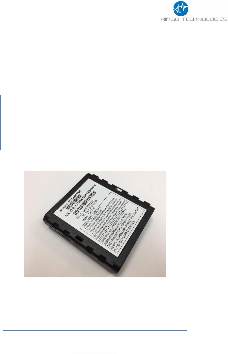
Regulatory Statements:
FCC ID:
Model: XT6372R
FCC ID: GKM-XT6372R
This product contains FCC ID: QIPELS31-V
FCC Information to User:
The XT6372R does not contain any user serviceable components and is to be used with approved antennas only.
Any product changes or modifications will invalidate all applicable regulatory certifications and approvals.
FCC Guidelines for Human Exposure:
The XT6372R complies with FCC radiation exposure limits set forth for an uncontrolled environment. This equipment
should be installed and operated with minimum distance of 20 cm between the radiator and your body.
This transmitter must not be co-located or operating in conjunction with any other antenna or transmitter.
FCC Declaration of Conformity:
The XT6372R complies with Part 15 Subpart B of FCC CFR47 Rules. Operation is subject to the following two
conditions:
1. This device may not cause harmful interference, and
2. This device must accept any interference received, including interference that may cause undesired operation.
FCC Radio Frequency Interference Warnings & Instructions:
The XT6372R has been tested and found to comply with the limits for a Class B digital device, pursuant to Part 15 of
the FCC Rules. These limits are designed to provide reasonable protection against harmful interference in a
residential installation. This equipment uses and can radiate radio frequency energy and, if not installed and used in
accordance with the instructions, may cause harmful interference to radio communications. However, there is no
guarantee that interference will not occur in a particular installation. If this equipment does cause harmful interference
to radio or television reception, which can be determined by turning the equipment off and on, the user is encouraged
to try to correct the interference by one or more of the following methods:
1. Reorient or relocate the receiving antenna.
2. Increase the separation between the equipment and the receiver.
3. Connect the equipment into an electrical outlet on a circuit different from that which the radio receiver is
connected.
4. Consult the dealer or an experienced radio/TV technician for help.

29
Sales Engineering
support@xirgotech.com
Industry Canada (IC):
IC: 10281A-XT6372R
This product contains IC: 7830A-ELS31V
This device complies with Industry Canada licence-exempt RSS standard(s). Operation is
subject to the following two conditions:
(1) this device may not cause interference, and
(2) this device must accept any interference, including interference that may cause
undesired operation of the device.
Le présent appareil est conforme aux CNR d'Industrie Canada applicables aux appareils
radio
exempts de licence. L'exploitation est autorisée aux deux conditions suivantes :
(1) l'appareil ne doit pas produire de brouillage, et
(2) l'utilisateur de l'appareil doit accepter tout brouillage radioélectrique subi, même si le
brouillage est susceptible d'en compromettre le onctionnement.
Under Industry Canada regulations, this radio transmitter may only operate using an
antenna of a type and maximum (or lesser) gain approved for the transmitter by Industry
Canada. To reduce potential radio interference to other users, the antenna type and its gain
should be so chosen that the equivalent isotropically radiated power (e.i.r.p.) is not more
than that necessary for successful communication.
Conformément à la réglementation d'Industrie Canada, le présent émetteur radio peut
fonctionner avec une antenne d'un type et d'un gain maximal (ou inférieur) approuvé pour
l'émetteur par Industrie Canada. Dans le but de réduire les risques de brouillage
radioélectrique à l'intention des autres utilisateurs, il faut choisir le type d'antenne et son
gain de sorte que la puissance isotrope rayonnée équivalente (p.i.r.e.) ne dépasse pas
l'intensité nécessaire à l'établissement d'une communication satisfaisante.
This radio transmitter (IC: 10281A-XT6372R, Model Number: XT6372R) has been approved
by Industry Canada to operate with the antenna types listed below with the maximum
permissible gain and required antenna impedance for each antenna type indicated. Antenna
types not included in this list, having a gain greater than the maximum gain indicated for
that type, are strictly prohibited for use with this device.
Cet émetteur radio (identifier le périphérique par numéro de certification, ou le numéro de modèle
si Catégorie II) a été approuvé par Industrie Canada pour fonctionner avec les types d'antennes
énumérées ci-dessous avec le gain maximal admissible et l'impédance d'antenne requise pour
chaque antenne type indiqué. Types d'antennes ne figurent pas dans cette liste, ayant un gain
supérieur au maximum gagner indiqué pour ce type, sont strictement interdites pour une utilisation
avec cet appareil..