Xmark ATG Asset Tag User Manual Manual
Xmark Corporation Asset Tag Manual
UserManual.wiki
>
Xmark
>
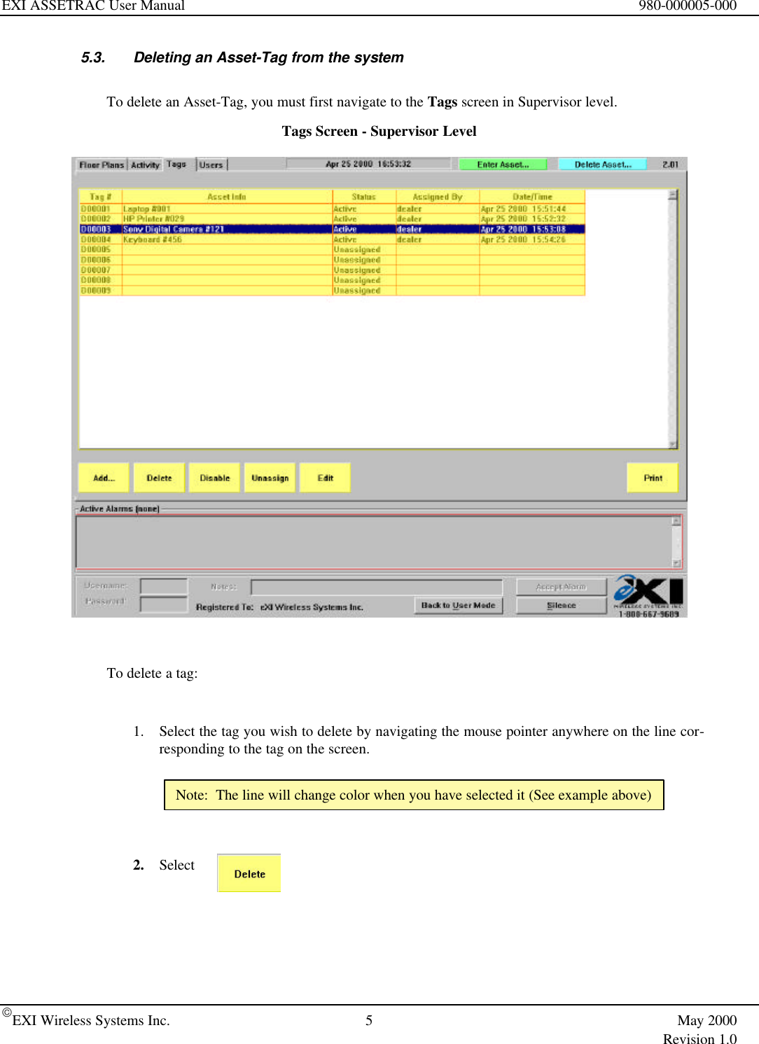
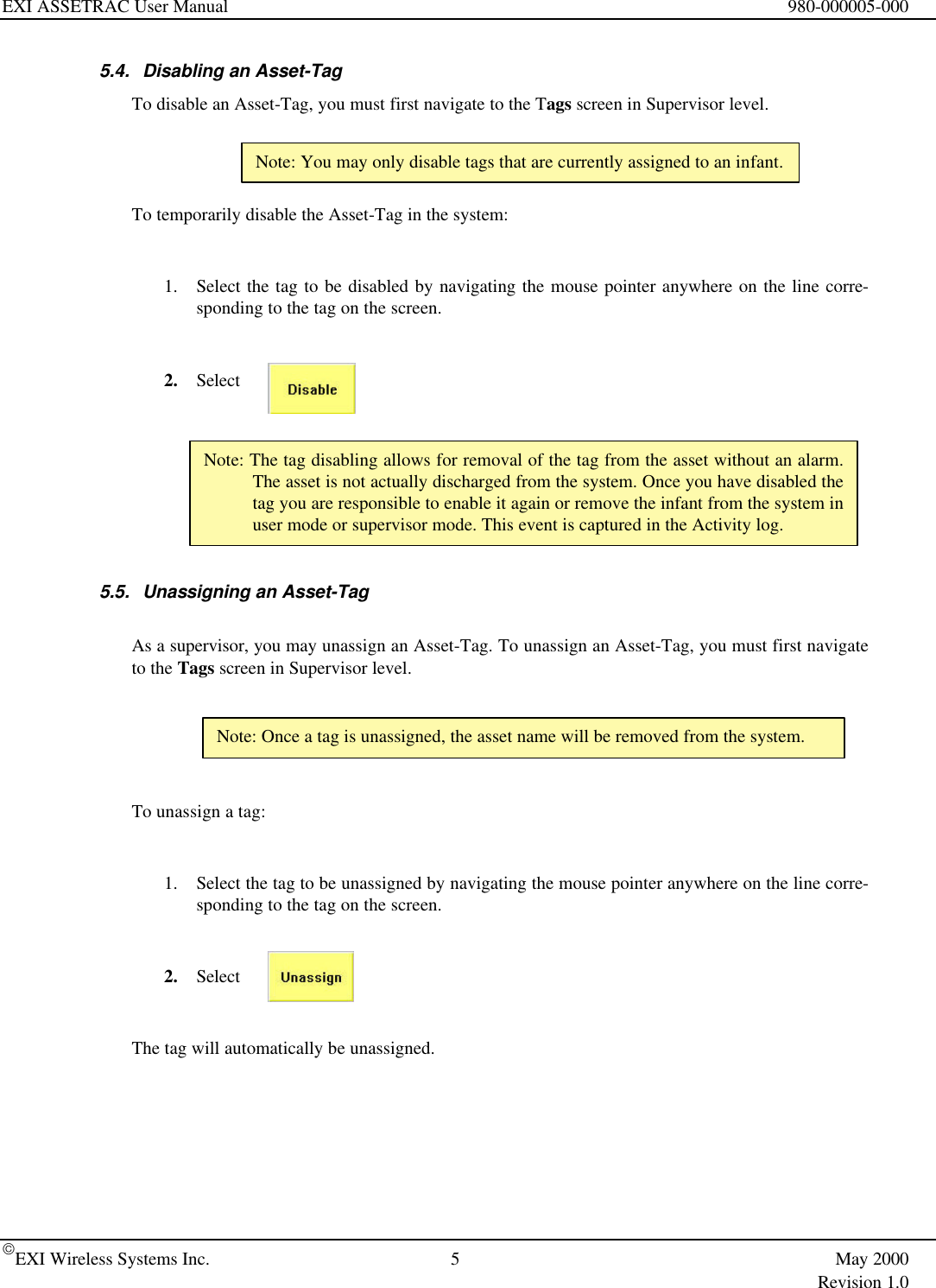
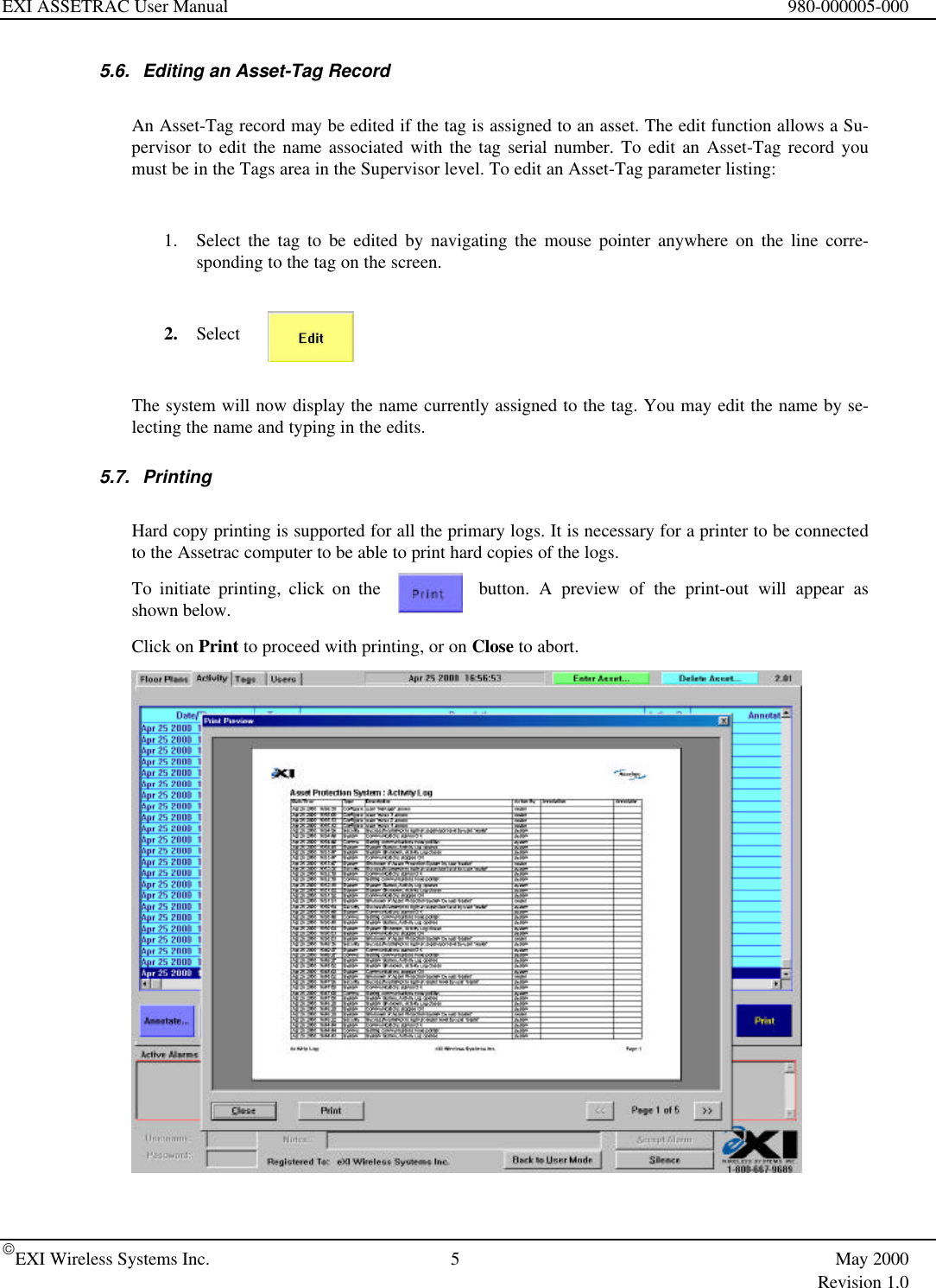
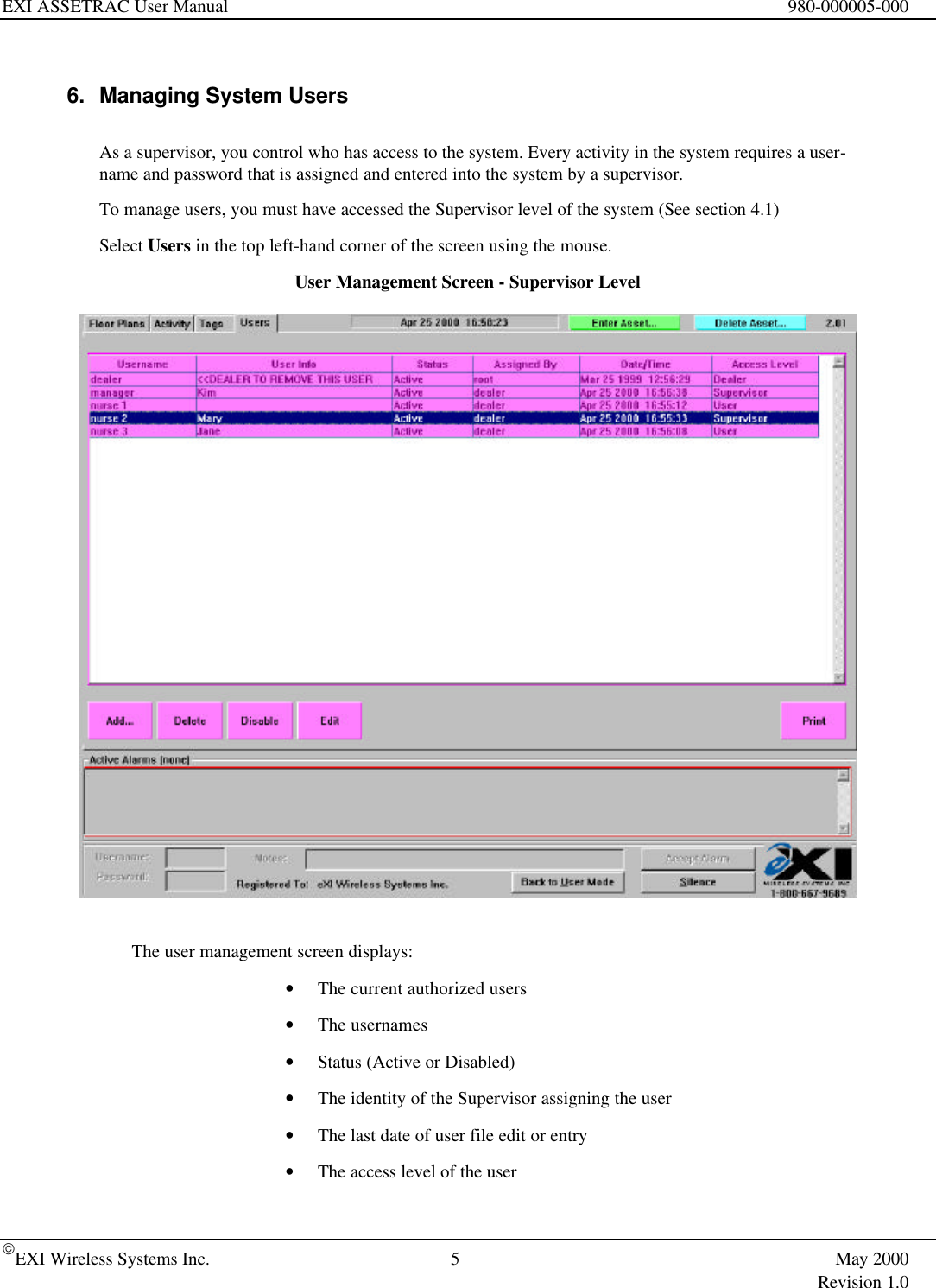
ATG User Manual
User manual
Navigation menu
Upload a User Manual
Namespaces
Wiki Guide
HTML
PDF
Info
Views
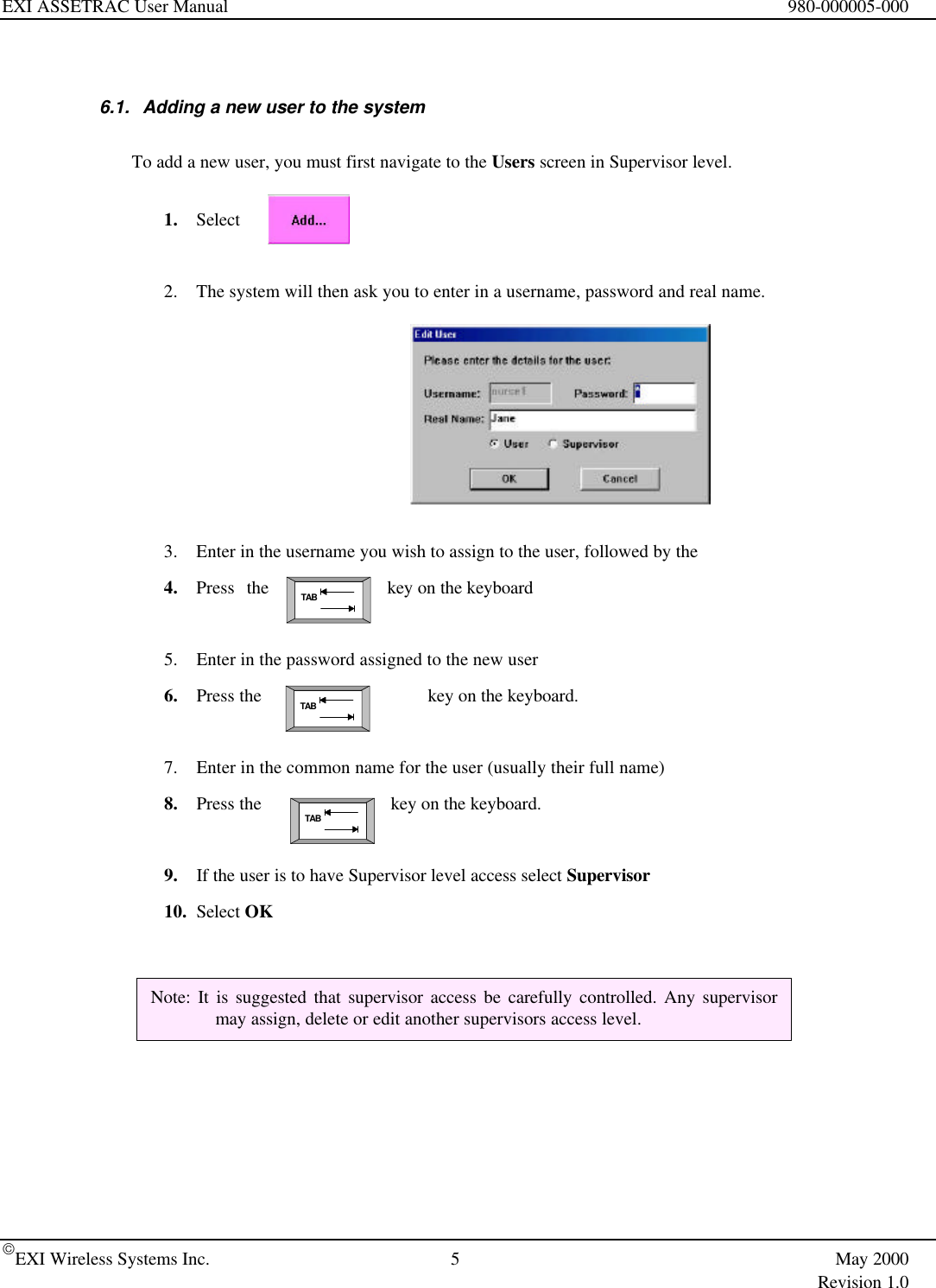
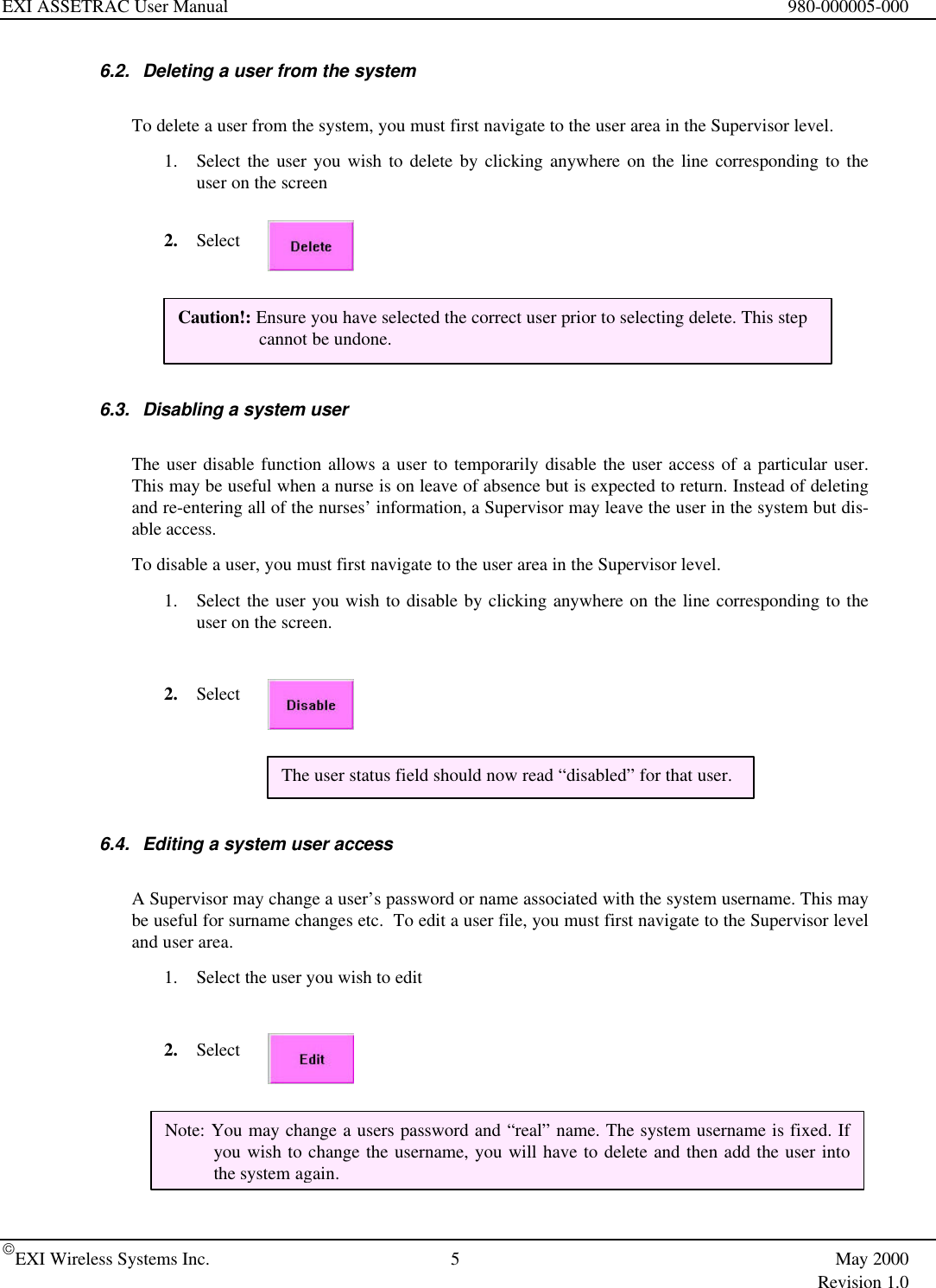
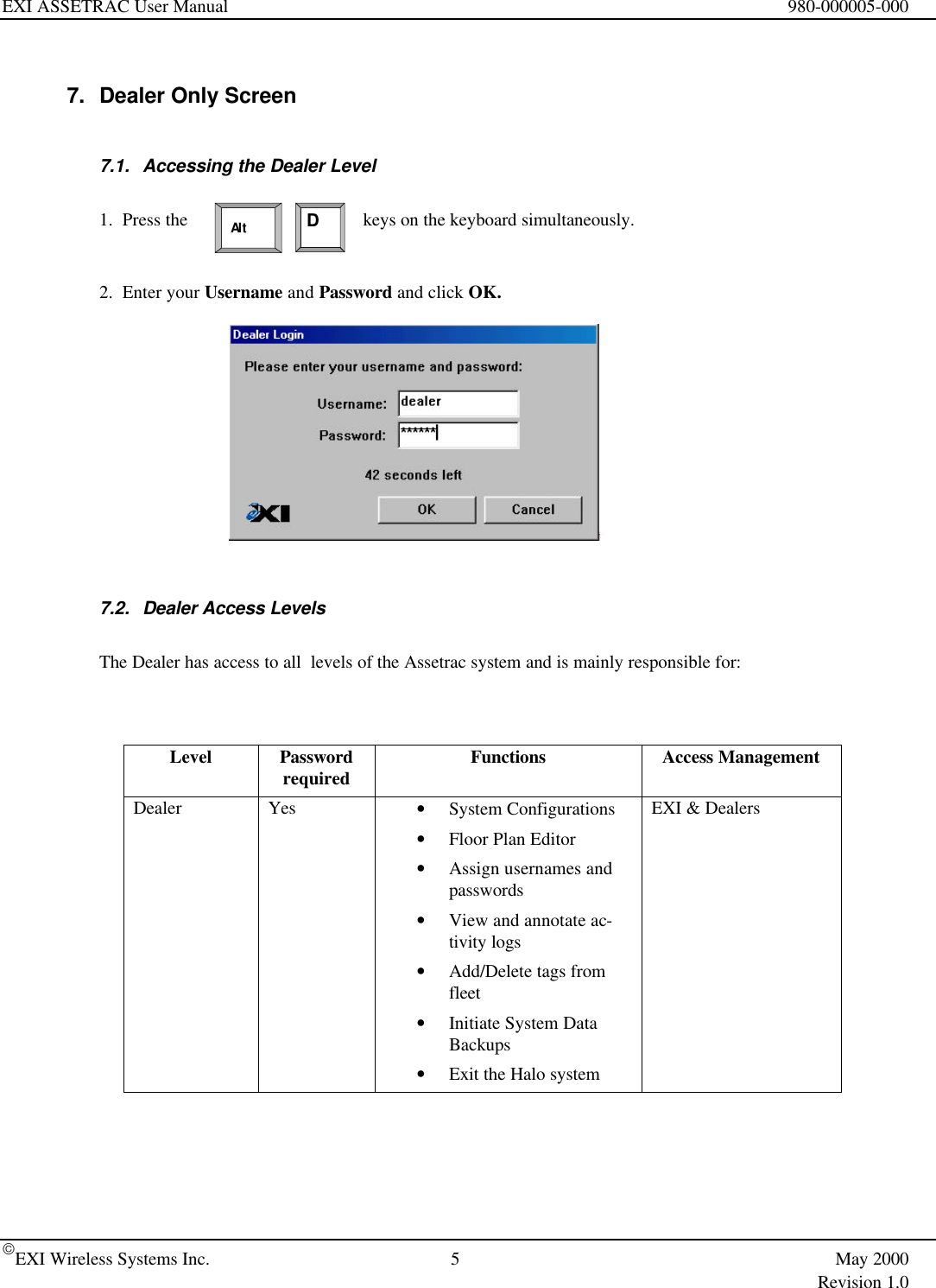
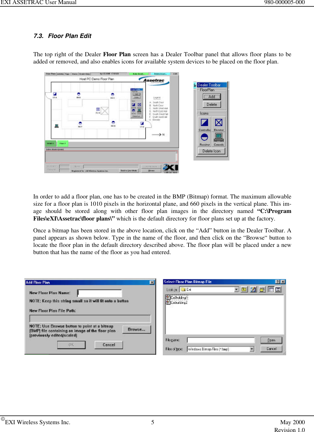
User Manual
Discussion / Help
Navigation