Xmark ILR International LAR 806A5301 User Manual 806U5301 Rev 01 indd
Xmark Corporation International LAR 806A5301 806U5301 Rev 01 indd
Xmark >
users manual
Materials Required
• Local Area Receiver (p/n 806A5301); includes antennas, Caddy
clip and mounting hardware.
• Facility fl oor plan indicating LAR position and network wiring
path.
• 105 Ω network terminator (p/n 805A2401) required to terminate
network. Two provided with each Controller (p/n 805A2201).
Important Reference Documents
• Hugs Installation Manual (p/n 805I0301)
• MyCall/FindIt Installation Manual (p/n 805I0401)
Materials Required
Important Reference Documents
Have
you:
• Pulled network and power cable?
• Resolved power supply requirements?
• Selected the location for the LAR?
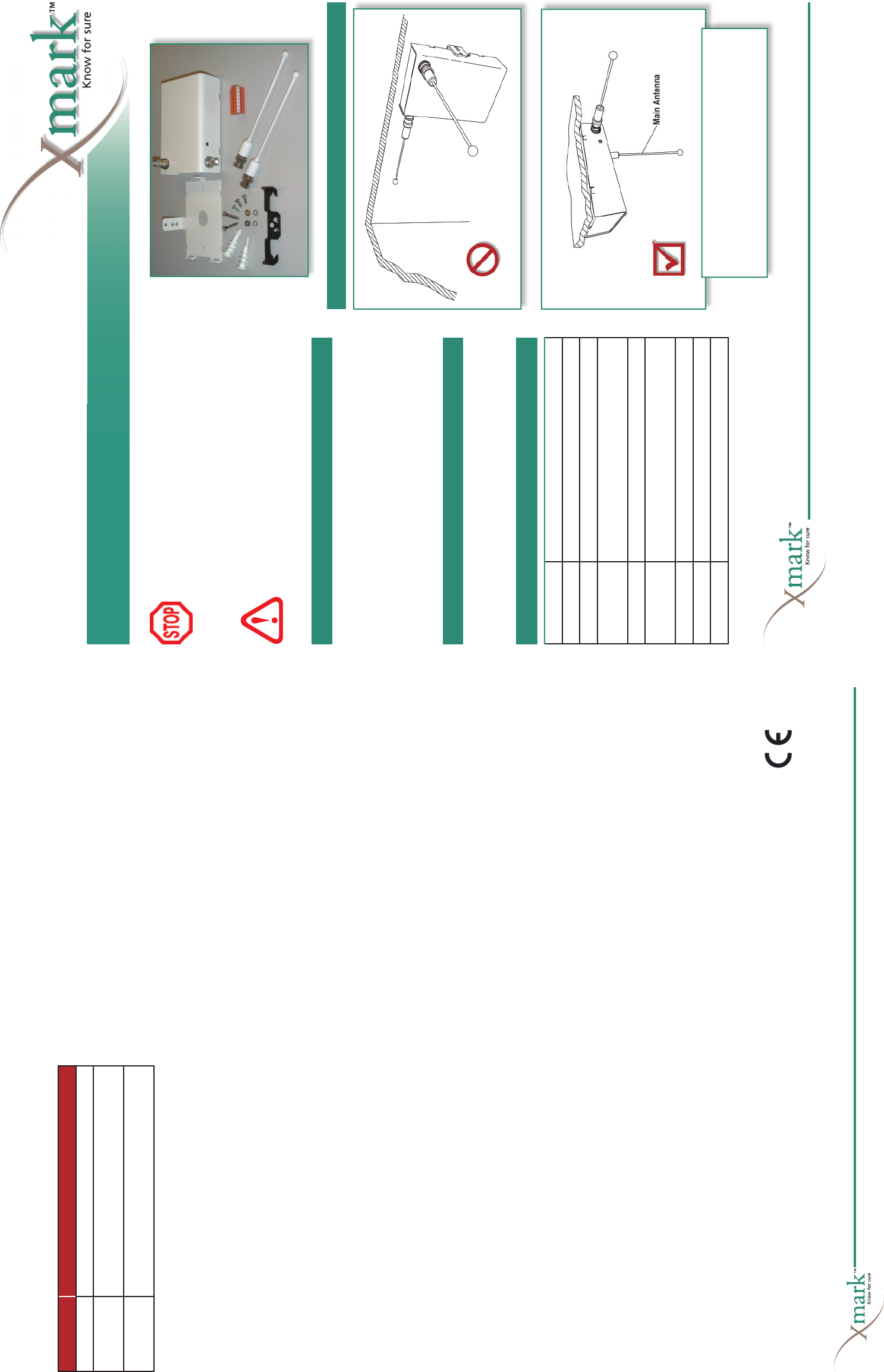
LAR Orientation
• Main antenna should be pointing downward into
an area free of metal obstructions.
• Ensure that the LAR is at least 2 ft. (60 cm) from
metal objects, such as framing or air ducts.
Specifi cations
Warranty
Xmark’s products are warranted against defects in materials and
workmanship and shall perform in accordance with published speci-
fi cations for a period of one year. Instantel Inc. reserves the right to
change specifi cations without notice.
Limitation of Liability
This Product has been designed for use to assist personnel in sum-
moning help when they are under personal duress and/or locate
assets.
The range, accuracy, function and performance of this Product
may vary from the published specifi cations due to many factors,
including, without limitation, site impairments from structural
effects, metal objects in the vicinity, placement of the receiver and
transmitter, interference from other electrical devices, atmospheric
effects, installation, and maintenance. There may be other factors,
which also affect performance of this Product.
Instantel does not guarantee that this Product will detect 100% of
the calls for personal assistance and locate all assets 100% of the time.
Instantel does not guarantee that this Product will not return false
reports of calls for personal assistance and/or location of assets.
Monthly testing and maintenance of this Product, as described in the
Product documentation, is essential to verify the system is operating
correctly and to ensure that the probability of detecting an alarm
and/or locating the transmitter are maximized.
The failure to undertake regular testing and maintenance will increase
the risk of system failure and failure to report personal duress calls
and/or failure to locate assets. The failure to undertake regular test-
ing and maintenance will increase the risk of false reports of calls for
personal assistance and/or location of assets.
Instantel hereby disclaims all warranties, express or implied, arising
out of or in connection with any of its Products of the use or perfor-
mance thereof, including but not limited to, where allowable by law,
all other implied warranties or conditions of merchantable quality
and fi tness for a particular purpose and those arising by statute or
otherwise in law or from a course of dealing or usage of trade.
Instantel’s liability to you or anyone claiming through or on behalf of
you with respect to any claim or loss arising out of the use or misuse
of Instantel’s Product, defective products or materials, improper
installation or maintenance of Instantel’s Product or products or the
system in which they are incorporated, or alleged to have resulted
from an act or omission of Instantel or any person, negligent or
otherwise, shall be limited to:
A) The repair or replacement of defective Product or materials sup-
plied by Instantel during the warranty period as set out in the
Product documentation; or, at the option of Instantel,
B) Refund of the purchase price of the Product supplied by Instan-
tel.
In no event shall Instantel be liable for general, specifi c, indirect,
consequential, incidental, exemplary or punitive damages or any
losses or expenses suffered by you or anyone else, whether or not
Instantel, or its employees, offi cers, agents, resellers or installers has
been informed of the risk of such loss or expense and whether or not
such losses or expenses were foreseeable.
Statements
United States—Federal Communication Commission (FCC)
This device complies with Part 15 of the FCC Rules. Operation
is subject to the following two conditions: (1) this device may not
cause harmful interference, and (2) this device must accept any
interference received, including interference that may cause unde-
sired operation.
NOTE: This equipment has been tested and found to comply with
the limits for a Class A digital device, pursuant to Part 15 of the FCC
Rules. These limits are designed to provide reasonable protection
against harmful interference when the equipment is operated in a
commercial environment. This equipment generates, uses, and can
radiate radio frequency energy and, if not installed and used in accor-
dance with the instruction manual, may cause harmful interference to
radio communications. Operation of this equipment in a residential
area is likely to cause harmful interference in which case the user will
be required to correct the interference at his own expense.
Warning: Changes or modifi cations not expressly approved by Xmark
could void the user’s authority to operate the equipment.
Canada—Industry Canada
The term “IC:” before the certifi cation/registration number only
signifi es that Industry Canada technical specifi cations were met.
European Union—CE declaration
Xmark hereby declares that this radio frequency receiver is in compli-
ance with the essential requirements and other relevant provisions
of Directive 1999/5/EC.
Service Light
The service light is located beside the secondary antenna, and indi-
cates the current status of the LAR, as shown in the table below.
Part Number 806A5301
Local Area Receiver Guide
© 2005 Xmark, a division of Instantel Inc. All Rights Reserved.
FindIt,
MyCall
and Hugs
are
registered trademarks of Instantel Inc. in North America. Xmark and the Xmark logo are trademarks of
Instantel Inc.
All other company and product names may be trademarks of their respective compa-
nies.
Printed in Canada. February 2005.
806U5301 Rev 01
.
808 Commerce Park Drive, Ogdensburg, NY 13669 USA or
309 Legget Drive, Ottawa, ON K2K 3A3, Canada
Telephone: 1-866-55-XMARK International: +1 613-592-6997 Facsimile: 1-613-592-4296
E-mail: sales@xmarksystems.com Web Site: www.xmarksystems.com
Certifi ed to the ISO 9001 Quality Standard
If you answered, “No,” to any of these questions, refer to the
MyCall/FindIt Installation Manual before installing.
LED state Meaning
Off Normal operation.
Flashing every
0.5 sec.
Unconfi gured LAR. Run Auto Confi gure in the LonWorks
Device Installation dialog box.
On Hardware failure. Download fi rmware to the LAR from
the LonWorks Device Installation dialog box.
Frequency 433.42 to 434.42 MHz
Supply Voltage 10-30 VDC
Current Draw 60 mA @ 12 / 24 VDC, 100 mA max.
Detection Radius 50 ft. (15 m) overlapping LARs
35 ft. (11 m) stand-alone LARs
Communications LonWorks two wire
Temperature Operating: 32°F to 120°F (0°C to 49°C)
Storage: -22° to 158° F (-30° to 70°C)
Humidity 0-85% RH @ 70°F (21°C), non-condensing
Dimensions Approximately 5.2 x 3.3 x 1.5 in. (133 x 84 x 38 mm)
Weight Approximately 9.2 oz. (260 g)
Read these instructions thoroughly
before installing the Local Area Receiver.
Faulty installation can lead to system failure.
DRAFT
Installing the Exciter
• Ensure that the power supply and network are turned
off to prevent electrical shock or damage to equip-
ment.
• Touch your hand to ground to discharge any electro-
static charge before handling the LAR.
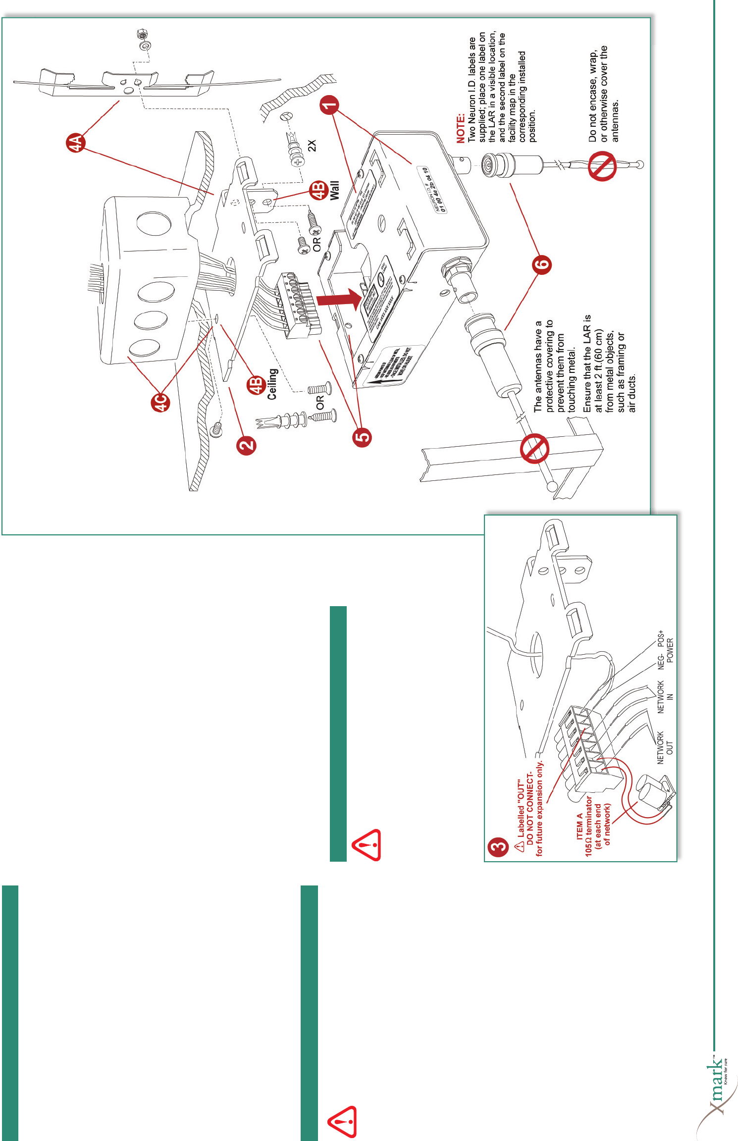
The steps below correspond to the numbers in Figure 1.
1 Record the LonWorks ID number.
Locate and record the LonWorks identifi cation number onto
the facility fl oor plan indicating the LAR’s position and network
wiring path. Use the tear-away sticker on the LAR’s Neuron ID
label.
2 Remove the Mounting Plate from the LAR.
If the LAR is to be installed to a receptacle box, pass the network
and power supply wires through the hole in the Mounting Plate.
(For other installations, the wires are passed through the slot on
the side of the LAR case in Step 5.)
3 Wire the terminal block.
Connect the LonWorks Network IN, Network OUT, and
Power Supply to the terminals. If the LAR is at the end of the
network, then terminate the network segment with Item A
(105 Ω terminator). Ensure there is at least 10 ft. (3 m) of slack
in the cable to allow the possible repositioning of the LAR.
4 Install the Mounting Plate.
Referring to the facility fl oor plan, decide the position of the LAR.
Do not place near metal objects and structural frames. Ensure
that the service light will be visible and that space is allowed for
the antennas. Unless there is a conduit tray, run the cables at least
1 ft. (30 cm) up and away from the LAR.
Install the mounting plate using one of the following methods.
A Fasten to a suspended ceiling guy wire, using:
• 1 multi-function Caddy clip
• 2 machine screws
• 2 hex nuts
• 2 lock washers
B Install directly to a ceiling or a wall using:
• 2 wood screws
• 2 hollow wall anchors
C Install to a receptacle box, using:
• 2 machine screws
5 Install the LAR to the Mounting Plate.
Plug the wired terminal block into the LAR and install the LAR
onto the Mounting Plate, using the screw removed in Step 2.
DO NOT place excess network and power supply wires inside
the LAR case.
6Attach the two antennas.
The antennas have a protective covering to prevent them from
touching metal. For best coverage, ensure that they are at least 2
ft. (60 cm) from metal objects. Do not encase, wrap, or otherwise
cover the antennas.
Installation is complete. Proceed to Final Steps below.
Figure 1: Physical connections for the LAR.
Installing the LAR
Installation Considerations
• Position the LAR beneath ceiling obstructions—When
mounting above drop ceilings, mount the LAR below metal duct
work, pipes and foil-backed ceiling tiles.
• Route cables up and away from the LAR—When the cable is
not in conduit, keep it at least 1 ft. (30 cm) from the LAR.
• Install the LAR temporarily until testing is complete—Fasten-
ings should be secure enough that the LAR can be permanently
mounted without disturbing its orientation.
• Point the secondary antenna into a clear area, away from
metal objects—The main antenna always points downwards,
but the orientation of the secondary antenna is adjusted to suit
site conditions. Point it away from metal objects, and make sure
it is not running parallel to cabling in the ceiling.
• Observe temperature and humidity restrictions—Refer to the
Specifi cations table.
• Leave slack in the cable—Leave at least 10 ft. (3 m) of slack in
the communication and power cable to allow for adjustments in
the location of the LAR.
• No user adjustments to internal circuitry—Tampering may
cause component or system failure, or both, and will void the
warranty.
Final Steps
Do not supply power to the LAR or any other network
device until all connections are complete.
Once all devices are installed, power up the LAR and other devices.
In the Xmark™ software, run Auto Confi gure to install the new
devices, and then confi gure them for operation.
The coverage area of the LAR must also be checked.
Refer to the Hugs Installation Manual (p/n 805I0301) or MyCall/
FindIt Installation Manual (p/n 805I0401) for detailed informa-
tion on how to complete these steps.
Installation Considerations
Final Steps
OR
OR