Xmark PTG Patient Tag User Manual Protocol

Xmark Corporation Patient Tag Protocol

Contents

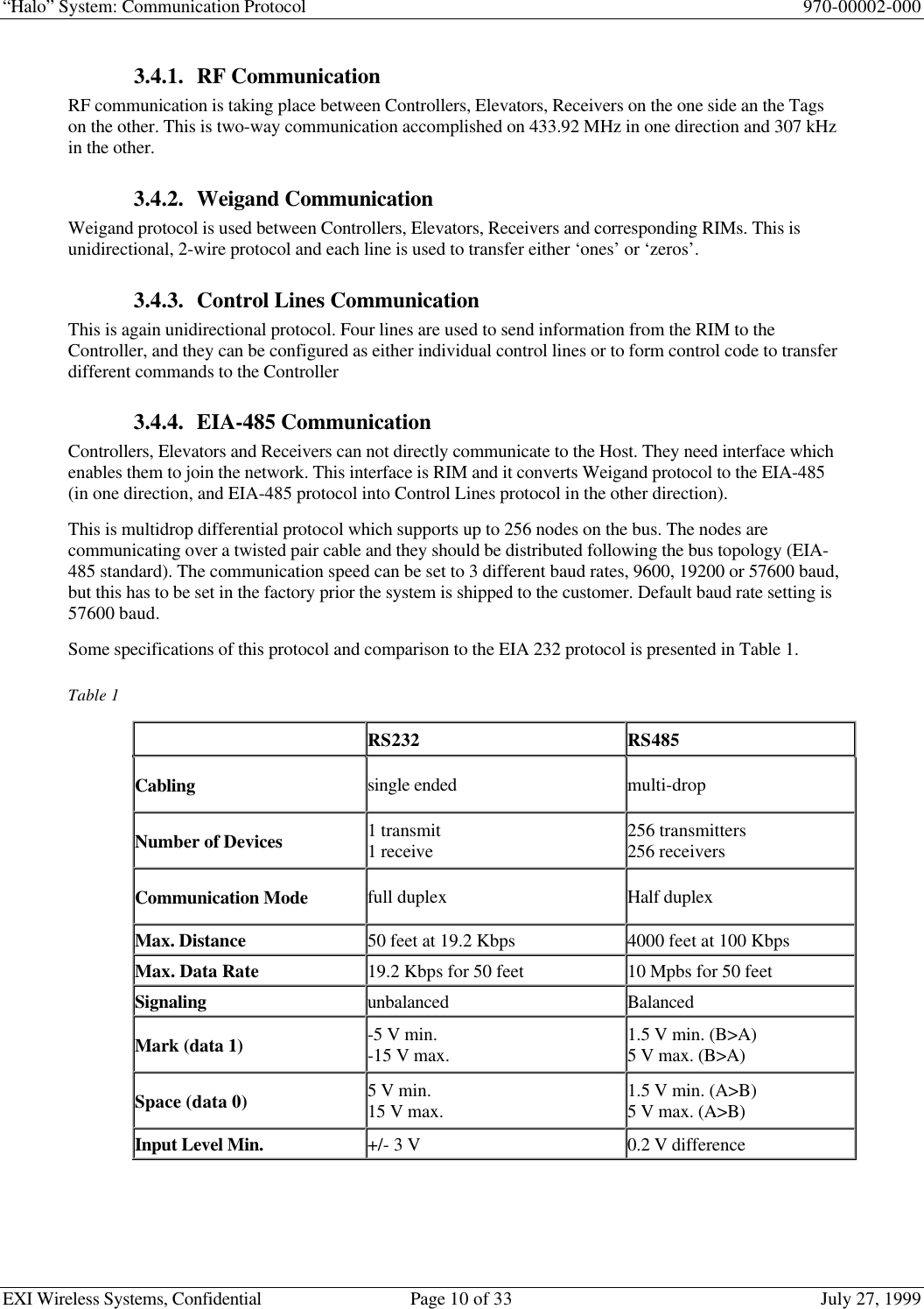
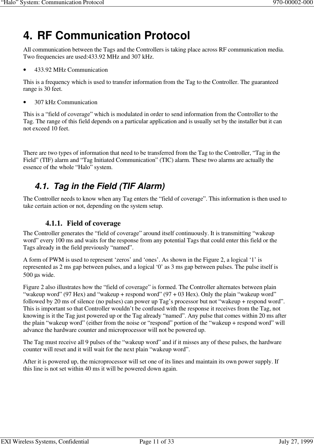
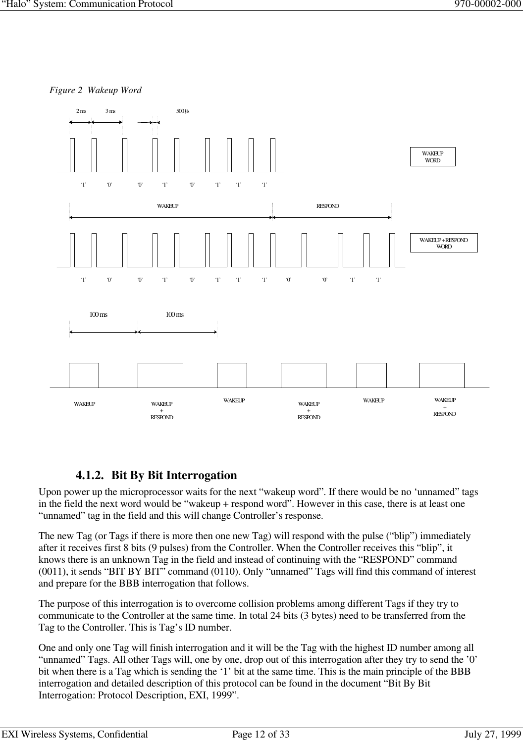
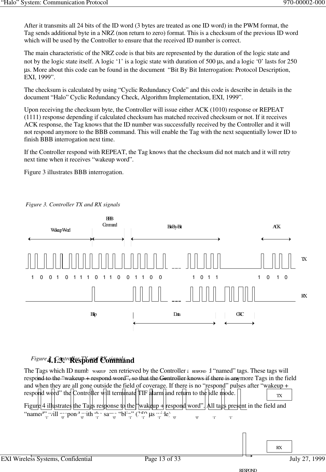
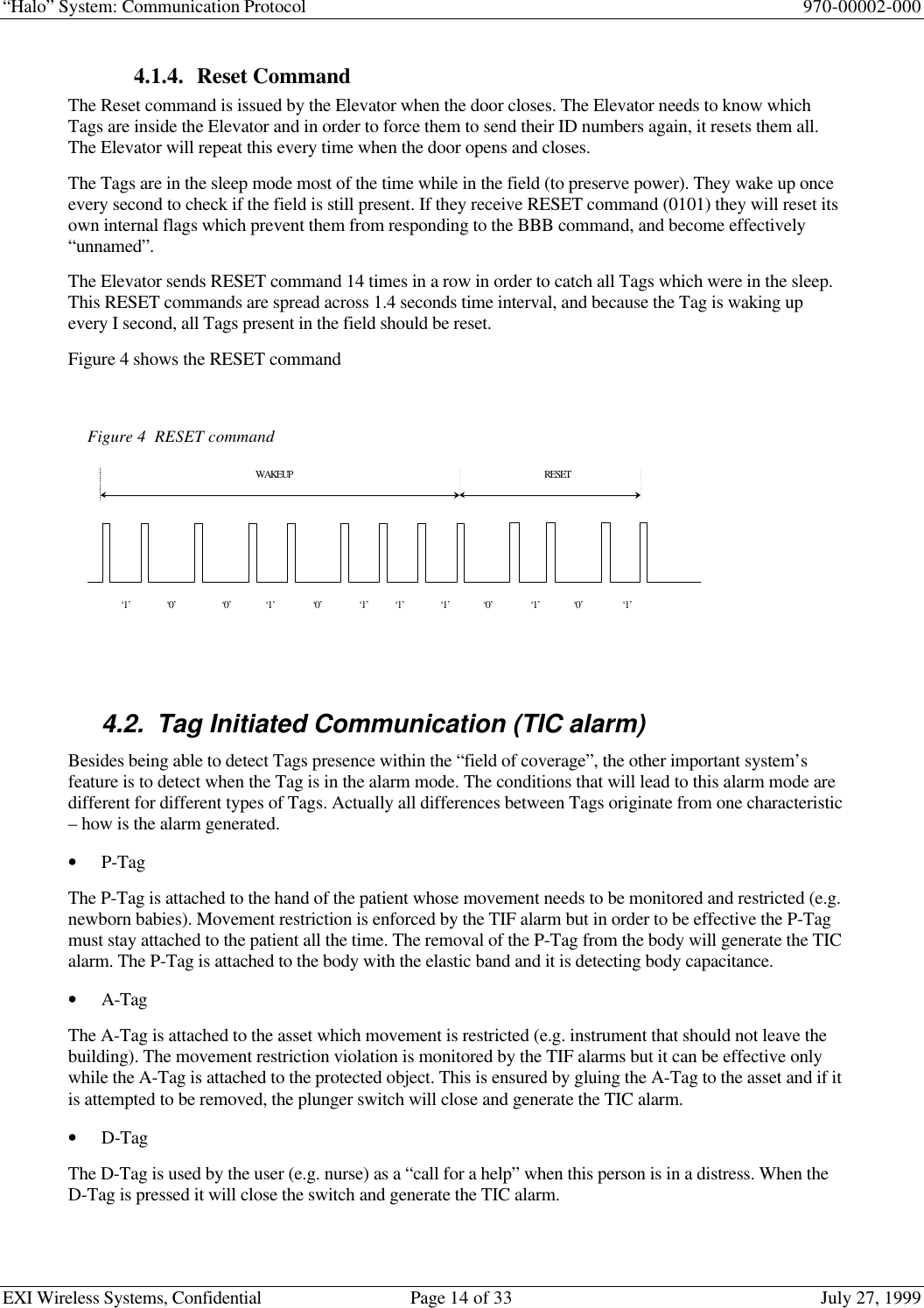
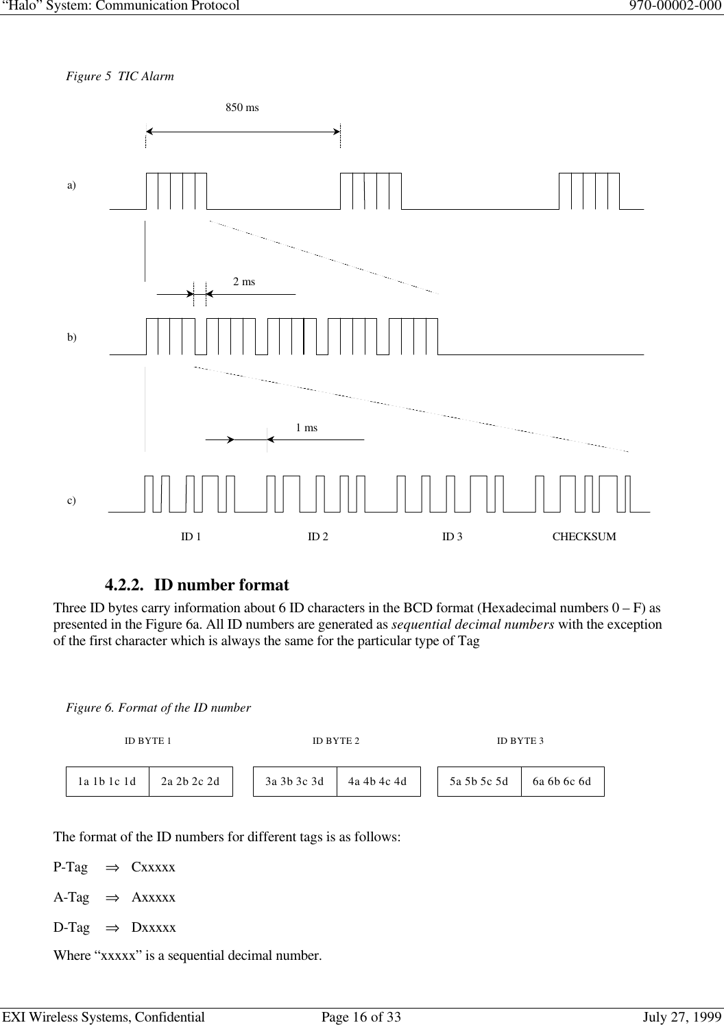
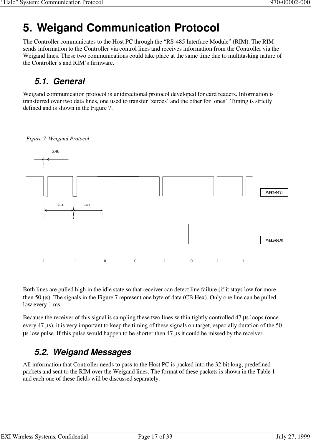
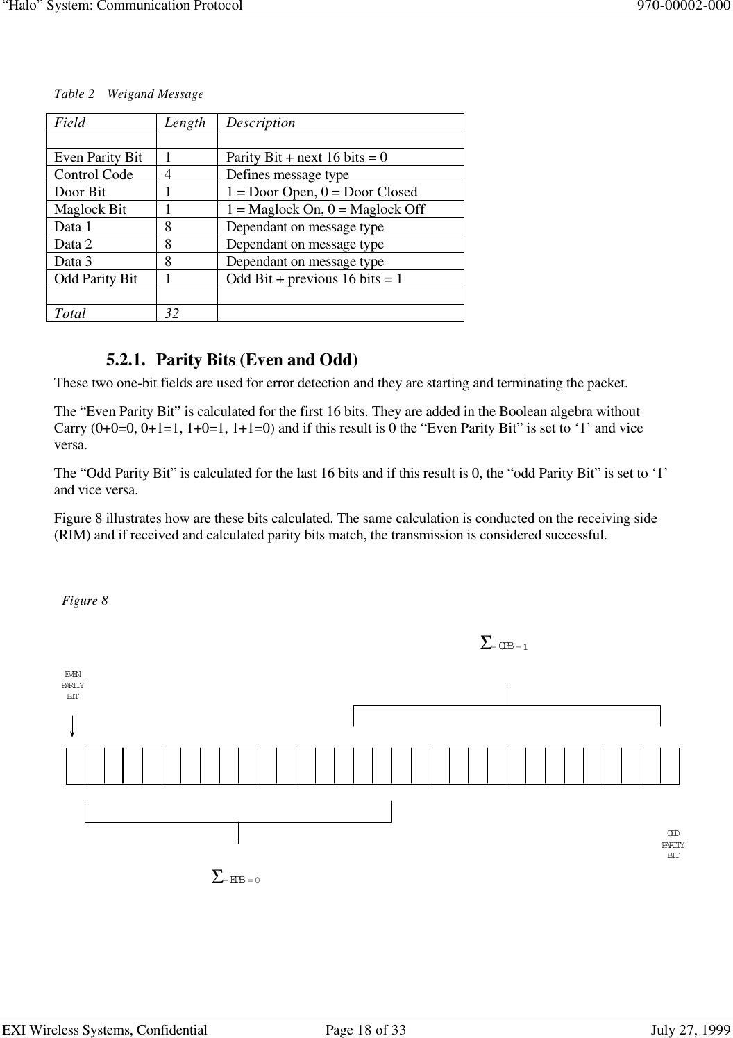
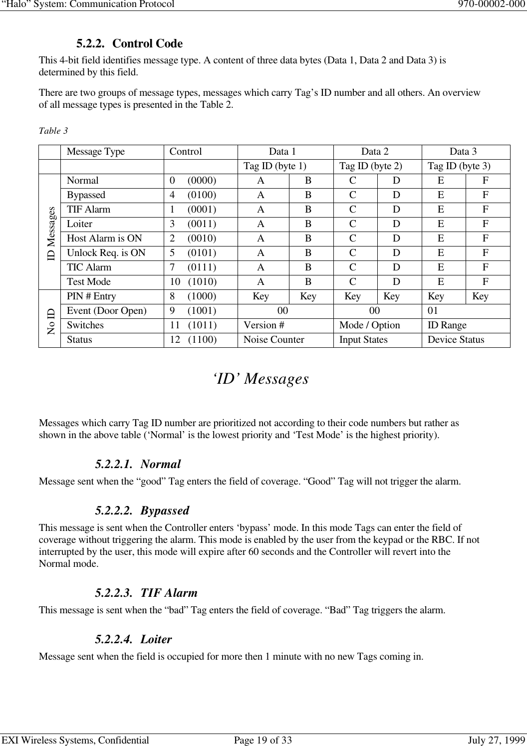
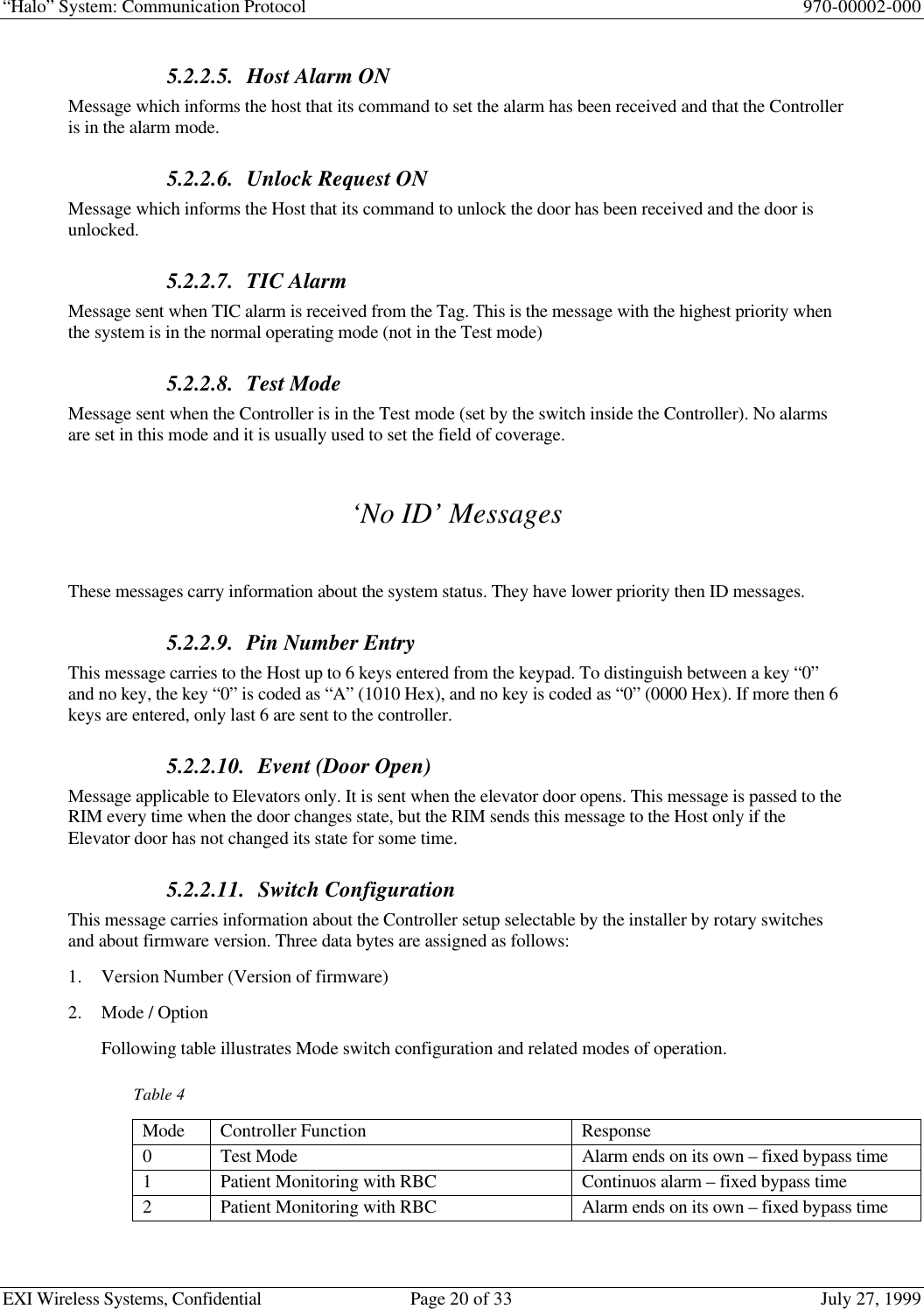
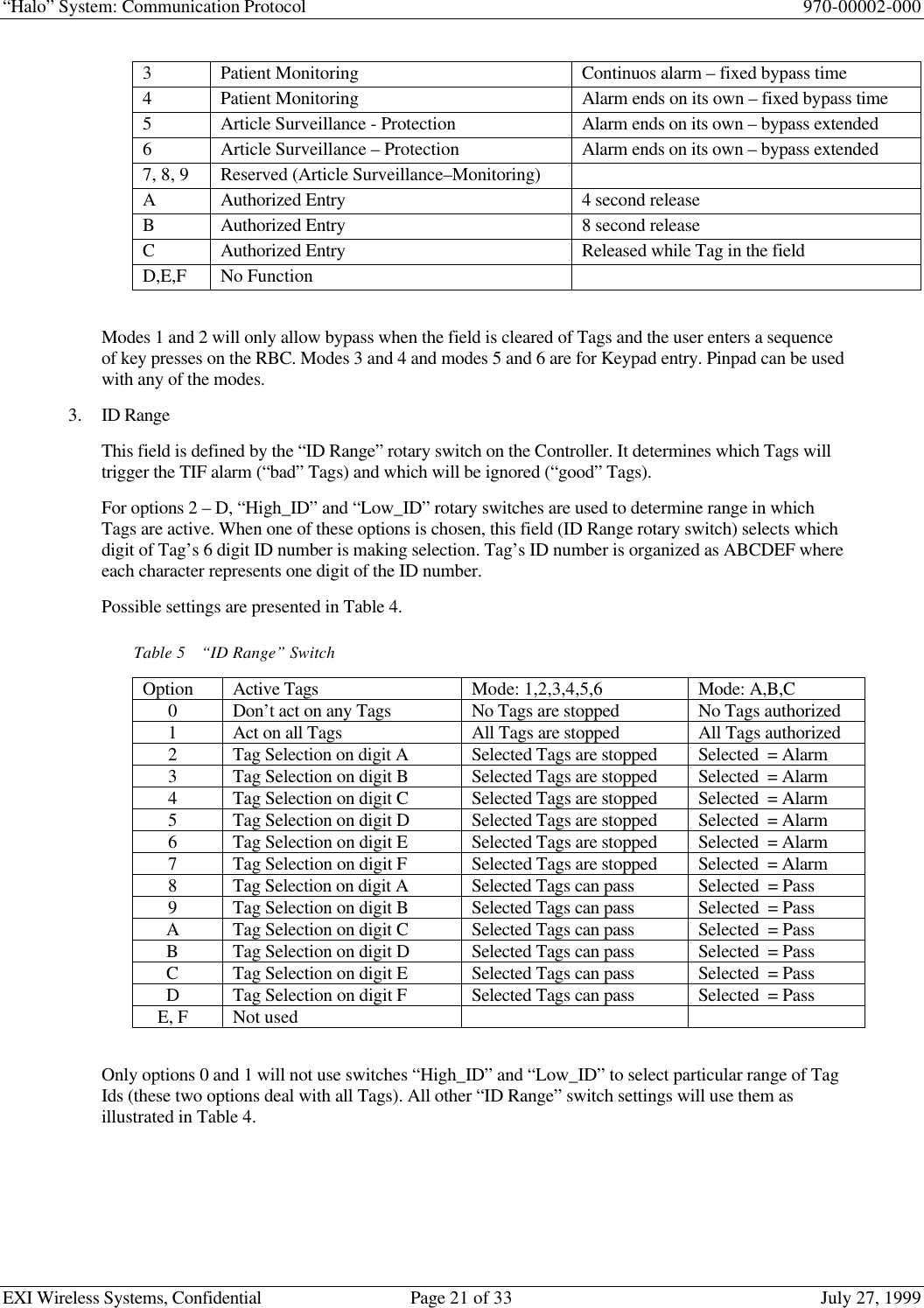
Communication Protocol manual

“Halo” SystemCommunication ProtocolRevision 0.1July 27, 1999970-00002-000
“Halo” System: Communication Protocol 970-00002-000EXI Wireless Systems, Confidential Page 2 of 33 July 27, 1999RevisionsVersion Date Changed by Description0.1 6/29/99 Dalibor Pokrajac Initial Release
“Halo” System: Communication Protocol 970-00002-000EXI Wireless Systems, Confidential Page 3 of 33 July 27, 1999ApprovalsCOO ______________________________________ Date: ___________________Engineering ______________________________________ Date: ___________________Manufacturing ______________________________________ Date: ___________________Quality ______________________________________ Date: ___________________Purchasing ______________________________________ Date: ___________________
“Halo” System: Communication Protocol 970-00002-000EXI Wireless Systems, Confidential Page 4 of 33 July 27, 19991. Document Purpose.......................................................................................................... 62. Introduction..................................................................................................................... 73. System Architecture......................................................................................................... 83.1. Host..............................................................................................................................83.2. Data Gathering and Control Nodes...........................................................................83.2.1. Controller...................................................................................................................................... 93.2.2. Elevator......................................................................................................................................... 93.2.3. Receiver......................................................................................................................................... 93.3. Sensors.........................................................................................................................93.4. Communication...........................................................................................................93.4.1. RF Communication....................................................................................................................103.4.2. Weigand Communication...........................................................................................................103.4.3. Control Lines Communication ..................................................................................................103.4.4. EIA-485 Communication...........................................................................................................104. RF Communication Protocol.......................................................................................114.1. Tag in the Field (TIF Alarm)....................................................................................114.1.1. Field of coverage ........................................................................................................................114.1.2. Bit By Bit Interrogation..............................................................................................................124.1.3. Respond Command.....................................................................................................................134.1.4. Reset Command..........................................................................................................................144.2. Tag Initiated Communication (TIC alarm) .............................................................144.2.1. Message format...........................................................................................................................15ID number format........................................................................................................................................165. Weigand Communication Protocol.............................................................................175.1. General ......................................................................................................................175.2. Weigand Messages....................................................................................................175.2.1. Parity Bits (Even and Odd).........................................................................................................185.2.2. Control Code...............................................................................................................................195.2.2.1. Normal................................................................................................................................195.2.2.2. Bypassed..............................................................................................................................195.2.2.3. TIF Alarm............................................................................................................................195.2.2.4. Loiter...................................................................................................................................195.2.2.5. Host Alarm ON...................................................................................................................205.2.2.6. Unlock Request ON ...........................................................................................................205.2.2.7. TIC Alarm...........................................................................................................................205.2.2.8. Test Mode ...........................................................................................................................205.2.2.9. Pin Number Entry...............................................................................................................205.2.2.10. Event (Door Open).............................................................................................................205.2.2.11. Switch Configuration.........................................................................................................205.2.2.12. Status...................................................................................................................................226. Signal lines communication.........................................................................................247. EIA-485 Communication.............................................................................................267.1. General ......................................................................................................................26
“Halo” System: Communication Protocol 970-00002-000EXI Wireless Systems, Confidential Page 5 of 33 July 27, 19997.2. Network performance ..............................................................................................267.3. Communication parameters.....................................................................................277.4. Message format.........................................................................................................277.5. Message Structure....................................................................................................287.5.1. Assign Network address .............................................................................................................287.5.2. Test Node Presence.....................................................................................................................297.5.3. Node Present...............................................................................................................................297.5.4. Send / Request Data....................................................................................................................297.5.5. Device Data.................................................................................................................................308. Glossary..........................................................................................................................329. References......................................................................................................................33
“Halo” System: Communication Protocol 970-00002-000EXI Wireless Systems, Confidential Page 6 of 33 July 27, 19991. Document PurposeThis document describes a communication protocol used by “HALO” system.This document is written after the system design has been finished and the objective is to describe structureof the system protocol, not only to people directly involved in the software and firmware design but toother technical personnel as well, involved in other aspects of system design, installation or technicalsupport.
“Halo” System: Communication Protocol 970-00002-000EXI Wireless Systems, Confidential Page 7 of 33 July 27, 19992. Introduction“Hallo” system is specialized data gathering and control system which is using different communicationmedia and protocols to achieve its tasks. The system consists of several major building blocks – Host,Controllers (Elevators, Receivers) and Tags.Data that are gathered are information sent by the Tags.The system can be used in different applications and some of them include:• Patient monitoring (P-Tag)This is primary application for the “Hallo” system. It can be used in the hospitals to prevent babiesabduction or to restrict movement for certain groups of patients that need to be monitored (e.g. Alzheimerpatients).• Asset monitoring (A-Tag)The “ Hallo” system can be used to prevent or warn of any unauthorized assets relocation (e.g. a notebookcomputer which shouldn’t leave the room or the building).• Distress monitoring (D-Tag)In this application D-Tags are used to signal some abnormal situation and they are activated by person whois carrying it. (e.g. a nurse threatened by a violent patient)Each one of these Tags is using the same protocol and has virtually the same functionality within thesystem. The difference is in peripheral sensing circuitry which will determine how are they activated. Inorder to simplify this protocol description, all of them will be referred to just as Tags.
“Halo” System: Communication Protocol 970-00002-000EXI Wireless Systems, Confidential Page 8 of 33 July 27, 19993. System ArchitectureThe “Hallo’ system can be classified into the group of data gathering and control systems and itscomponents could be divided into 3 major groups:• Host (Computer)• Data gathering and control nodes (Controllers, Elevators, Receivers, Printer Interface, Programmers)• Sensors (P-Tag, A-Tag, D-Tag)Figure 1 shows how these units are organized within the system.3.1. HostThe Host is Windows based User Interface running on a PC. It serves as a terminal from which the user canmonitor the system operation and exercise available controls. There can be only one Host and it is acting asa Master device within the system. The Host must be equipped with the EIA-485 / EIA-232 converter inorder to be able to communicate to the rest of the system.3.2. Data Gathering and Control NodesThere are 3 types of the nodes in this group and they vary in their functionality, but one feature is commonamong all of them; they are all able to communicate to the Tags and to the Host. These are two completelydifferent communication paths and will be examined in details in this documentFigure 1Controller ElevatorHost PCRIMRIMRIMReceiverRIMReceiverTagTagTagTagTagTagTagTagTag
“Halo” System: Communication Protocol 970-00002-000EXI Wireless Systems, Confidential Page 9 of 33 July 27, 19993.2.1. ControllerThe Controller is used to monitor and control the area in which it is installed, usually near the door. Itgenerates the “field of coverage” around itself and any Tag entering this field will be registered by theController (Tag In the Field (TIF) alarm). The other Controller’s task is to register if any of the Tags aresending TIC alarm. When the Tag enters this mode depends on particular type of the Tag, but thecommunication principle is always the same.These alarms are passed to the Host via “RS-485 Interface Module” (RIM) which serves as an interface tothe RS-485 based network.The Controller can be programmed to respond or not to a particular Tag, and when it does respond it cantake certain actions; lock / unlock the door, activate audible alarm and control any external device via therelay.3.2.2. ElevatorThe Elevator node is special version of the Controller node. While the Controller is intended to cover thearea near the door, the elevator application has to be approached differently to avoid false alarm triggeringdue to somebody just walking near the elevator and to avoid installing separate Controller on the everyfloor, just to mention two most important reasons.The Elevator communication to the Host is almost identical to the Controller.3.2.3. ReceiverThe Receiver is a node which will respond to TIC alarms only. It has limited control functionality (onerelay) and it can not receive any commands from the Host. The idea behind the Receiver concept is toblanket the building with low cost nodes in order to reliably register TIC alarm. The Controllers could beused for this purpose but they are not cost effective.The Receiver communicates with the Host in similar fashion as the Controller but with limitedfunctionality.3.3. SensorsTags are the only sensors in this system (if we disregard door open / closed sensing by a Controller and anElevator). There could be different types of tags within the system as discussed earlier, but all of them havecommon characteristic to be able to communicate to the Controllers, Elevators or Receivers by usingcommon protocol.3.4. CommunicationThere are 4 different communication protocols used in this system and the difference among them isdetermined mostly by communication media used.Figure 2HOST TAGCONTROLLERRIM485 CommControl LinesCommWeigandCommRF Comm
“Halo” System: Communication Protocol 970-00002-000EXI Wireless Systems, Confidential Page 10 of 33 July 27, 19993.4.1. RF CommunicationRF communication is taking place between Controllers, Elevators, Receivers on the one side an the Tagson the other. This is two-way communication accomplished on 433.92 MHz in one direction and 307 kHzin the other.3.4.2. Weigand CommunicationWeigand protocol is used between Controllers, Elevators, Receivers and corresponding RIMs. This isunidirectional, 2-wire protocol and each line is used to transfer either ‘ones’ or ‘zeros’.3.4.3. Control Lines CommunicationThis is again unidirectional protocol. Four lines are used to send information from the RIM to theController, and they can be configured as either individual control lines or to form control code to transferdifferent commands to the Controller3.4.4. EIA-485 CommunicationControllers, Elevators and Receivers can not directly communicate to the Host. They need interface whichenables them to join the network. This interface is RIM and it converts Weigand protocol to the EIA-485(in one direction, and EIA-485 protocol into Control Lines protocol in the other direction).This is multidrop differential protocol which supports up to 256 nodes on the bus. The nodes arecommunicating over a twisted pair cable and they should be distributed following the bus topology (EIA-485 standard). The communication speed can be set to 3 different baud rates, 9600, 19200 or 57600 baud,but this has to be set in the factory prior the system is shipped to the customer. Default baud rate setting is57600 baud.Some specifications of this protocol and comparison to the EIA 232 protocol is presented in Table 1.Table 1RS232 RS485Cabling single ended multi-dropNumber of Devices 1 transmit1 receive 256 transmitters256 receiversCommunication Mode full duplex Half duplexMax. Distance 50 feet at 19.2 Kbps 4000 feet at 100 KbpsMax. Data Rate 19.2 Kbps for 50 feet 10 Mpbs for 50 feetSignaling unbalanced BalancedMark (data 1) -5 V min.-15 V max. 1.5 V min. (B>A)5 V max. (B>A)Space (data 0) 5 V min.15 V max. 1.5 V min. (A>B)5 V max. (A>B)Input Level Min. +/- 3 V 0.2 V difference
“Halo” System: Communication Protocol 970-00002-000EXI Wireless Systems, Confidential Page 11 of 33 July 27, 19994. RF Communication ProtocolAll communication between the Tags and the Controllers is taking place across RF communication media.Two frequencies are used:433.92 MHz and 307 kHz.• 433.92 MHz CommunicationThis is a frequency which is used to transfer information from the Tag to the Controller. The guaranteedrange is 30 feet.• 307 kHz CommunicationThis is a “field of coverage” which is modulated in order to send information from the Controller to theTag. The range of this field depends on a particular application and is usually set by the installer but it cannot exceed 10 feet.There are two types of information that need to be transferred from the Tag to the Controller, “Tag in theField” (TIF) alarm and “Tag Initiated Communication” (TIC) alarm. These two alarms are actually theessence of the whole “Halo” system.4.1. Tag in the Field (TIF Alarm)The Controller needs to know when any Tag enters the “field of coverage”. This information is then used totake certain action or not, depending on the system setup.4.1.1. Field of coverageThe Controller generates the “field of coverage” around itself continuously. It is transmitting “wakeupword” every 100 ms and waits for the response from any potential Tags that could enter this field or theTags already in the field previously “named”.A form of PWM is used to represent ‘zeros’ and ‘ones’. As shown in the Figure 2, a logical ‘1’ isrepresented as 2 ms gap between pulses, and a logical ‘0’ as 3 ms gap between pulses. The pulse itself is500 µs wide.Figure 2 also illustrates how the “field of coverage” is formed. The Controller alternates between plain“wakeup word” (97 Hex) and “wakeup + respond word” (97 + 03 Hex). Only the plain “wakeup word”followed by 20 ms of silence (no pulses) can power up Tag’s processor but not “wakeup + respond word”.This is important so that Controller wouldn’t be confused with the response it receives from the Tag, notknowing is it the Tag just powered up or the Tag already “named”. Any pulse that comes within 20 ms afterthe plain “wakeup word” (either from the noise or “respond” portion of the “wakeup + respond word” willadvance the hardware counter and microprocessor will not be powered up.The Tag must receive all 9 pulses of the “wakeup word” and if it misses any of these pulses, the hardwarecounter will reset and it will wait for the next plain “wakeup word”.After it is powered up, the microprocessor will set one of its lines and maintain its own power supply. Ifthis line is not set within 40 ms it will be powered down again.
“Halo” System: Communication Protocol 970-00002-000EXI Wireless Systems, Confidential Page 12 of 33 July 27, 19994.1.2. Bit By Bit InterrogationUpon power up the microprocessor waits for the next “wakeup word”. If there would be no ‘unnamed” tagsin the field the next word would be “wakeup + respond word”. However in this case, there is at least one“unnamed” tag in the field and this will change Controller’s response.The new Tag (or Tags if there is more then one new Tag) will respond with the pulse (“blip”) immediatelyafter it receives first 8 bits (9 pulses) from the Controller. When the Controller receives this “blip”, itknows there is an unknown Tag in the field and instead of continuing with the “RESPOND” command(0011), it sends “BIT BY BIT” command (0110). Only “unnamed” Tags will find this command of interestand prepare for the BBB interrogation that follows.The purpose of this interrogation is to overcome collision problems among different Tags if they try tocommunicate to the Controller at the same time. In total 24 bits (3 bytes) need to be transferred from theTag to the Controller. This is Tag’s ID number.One and only one Tag will finish interrogation and it will be the Tag with the highest ID number among all“unnamed” Tags. All other Tags will, one by one, drop out of this interrogation after they try to send the ’0’bit when there is a Tag which is sending the ‘1’ bit at the same time. This is the main principle of the BBBinterrogation and detailed description of this protocol can be found in the document “Bit By BitInterrogation: Protocol Description, EXI, 1999”.Figure 2  Wakeup Word‘1’‘0’2 ms3 ms500 µs‘0’‘0’‘1’‘1’‘1’‘1’‘1’‘0’WAKEUP‘0’‘0’‘1’‘1’‘1’‘1’‘0’‘1’‘0’‘1’RESPONDWAKEUPWORDWAKEUP + RESPONDWORD100 ms 100 msWAKEUPWAKEUPWAKEUPWAKEUP+RESPONDWAKEUP+RESPONDWAKEUP+RESPOND
“Halo” System: Communication Protocol 970-00002-000EXI Wireless Systems, Confidential Page 13 of 33 July 27, 1999After it transmits all 24 bits of the ID word (3 bytes are treated as one ID word) in the PWM format, theTag sends additional byte in a NRZ (non return to zero) format. This is a checksum of the previous ID wordwhich will be used by the Controller to ensure that the received ID number is correct.The main characteristic of the NRZ code is that bits are represented by the duration of the logic state andnot by the logic state itself. A logic ‘1’ is a logic state with duration of 500 µs, and a logic ‘0’ lasts for 250µs. More about this code can be found in the document  “Bit By Bit Interrogation: Protocol Description,EXI, 1999”.The checksum is calculated by using “Cyclic Redundancy Code” and this code is describe in details in thedocument “Halo” Cyclic Redundancy Check, Algorithm Implementation, EXI, 1999”.Upon receiving the checksum byte, the Controller will issue either ACK (1010) response or REPEAT(1111) response depending if calculated checksum has matched received checksum or not. If it receivesACK response, the Tag knows that the ID number was successfully received by the Controller and it willnot respond anymore to the BBB command. This will enable the Tag with the next sequentially lower ID tofinish BBB interrogation next time.If the Controller respond with REPEAT, the Tag knows that the checksum did not match and it will retrynext time when it receives “wakeup word”.Figure 3 illustrates BBB interrogation.4.1.3. Respond CommandThe Tags which ID number has been retrieved by the Controller are called “named” tags. These tags willrespond to the “wakeup + respond word”, so that the Controller knows if there is anymore Tags in the fieldand when they are all gone outside the field of coverage. If there is no “respond” pulses after “wakeup +respond word” the Controller will terminate TIF alarm and return to the idle mode.Figure 4 illustrates the Tags response to the “wakeup + respond word”. All tags present in the field and“named” will respond with the same “blip” (350 µs wide).Figure 3. Controller TX and RX signalsWakeup WordBBBCommand Bit-By-Bit ACKData CRCTXRX1        0        0      1        0       1     1      1       0       1     1       0        0       1      1       0        0                                   1       0      1       1                                             1        0         1       0BlipFigure 2  Controller TX and RX signals‘1’‘0’WAKEUP‘0’‘0’‘1’‘1’‘1’‘1’‘0’‘1’‘0’‘1’RESPONDTXRXRESPOND
“Halo” System: Communication Protocol 970-00002-000EXI Wireless Systems, Confidential Page 14 of 33 July 27, 19994.1.4. Reset CommandThe Reset command is issued by the Elevator when the door closes. The Elevator needs to know whichTags are inside the Elevator and in order to force them to send their ID numbers again, it resets them all.The Elevator will repeat this every time when the door opens and closes.The Tags are in the sleep mode most of the time while in the field (to preserve power). They wake up onceevery second to check if the field is still present. If they receive RESET command (0101) they will reset itsown internal flags which prevent them from responding to the BBB command, and become effectively“unnamed”.The Elevator sends RESET command 14 times in a row in order to catch all Tags which were in the sleep.This RESET commands are spread across 1.4 seconds time interval, and because the Tag is waking upevery I second, all Tags present in the field should be reset.Figure 4 shows the RESET command4.2. Tag Initiated Communication (TIC alarm)Besides being able to detect Tags presence within the “field of coverage”, the other important system’sfeature is to detect when the Tag is in the alarm mode. The conditions that will lead to this alarm mode aredifferent for different types of Tags. Actually all differences between Tags originate from one characteristic– how is the alarm generated.• P-TagThe P-Tag is attached to the hand of the patient whose movement needs to be monitored and restricted (e.g.newborn babies). Movement restriction is enforced by the TIF alarm but in order to be effective the P-Tagmust stay attached to the patient all the time. The removal of the P-Tag from the body will generate the TICalarm. The P-Tag is attached to the body with the elastic band and it is detecting body capacitance.• A-TagThe A-Tag is attached to the asset which movement is restricted (e.g. instrument that should not leave thebuilding). The movement restriction violation is monitored by the TIF alarms but it can be effective onlywhile the A-Tag is attached to the protected object. This is ensured by gluing the A-Tag to the asset and if itis attempted to be removed, the plunger switch will close and generate the TIC alarm.• D-TagThe D-Tag is used by the user (e.g. nurse) as a “call for a help” when this person is in a distress. When theD-Tag is pressed it will close the switch and generate the TIC alarm.Figure 4  RESET command‘1’‘0’WAKEUP‘0’‘0’‘1’‘1’‘1’‘1’‘1’‘0’‘0’‘1’RESET
“Halo” System: Communication Protocol 970-00002-000EXI Wireless Systems, Confidential Page 15 of 33 July 27, 19994.2.1. Message formatThe Tag (any of the above) is powered down most of the time and it powers up only when it enters the“field of coverage” (TIF) or when it needs to generate the TIC alarm.The TIC alarm range should be much longer than a TIF alarm and this is accomplished with some tradeoffs.The most important factor is that TIC communication can not be 2-way communication due to the natureof the Tags 2-way communication (field of coverage has limited range). This determines the format of theTIC message sent from the Tag to the Controller.To improve the chances that the message will go through (without the acknowledgment it can not beguarantied nor the Tag knows if the message has been received correctly by the Controller), it is sent in 3bursts and 5 times within each burst as shown in the Figure 5. This is 15 ID messages in total sent everytime when the TIC is generated. If any of these messages comes through, the transmission is successful.After receiving each one of these ID messages the Controller compares received checksum with calculatedCRC and if they are the same, ignores all other messages with the same ID number for next 2 seconds.The message is formatted in the NRZ code (same protocol as described earlier). Each individual IDmessage consists of 3 ID bytes (coded as 6 BCD numbers) and one byte for the checksum (same CRCcalculation as described for “Bit-By-Bit” protocol).After each burst (with 5 ID messages) the microprocessor goes into the sleep mode. The bursts aregenerated every 850 ms (Figure 5a).Figure 5b illustrates one of the bursts. The ID messages are separated with 2 ms of silence. This time isused by the Controller to calculate the CRC.The ID message format is shown in the Figure 5c. There are 4 bytes in the NRZ code where a logic ‘0’ isrepresented with the 250 µs pulse and a logic ‘1’ with the 500 µs pulse. Each byte is terminated with the“stop bit”. There is 1 ms gap between each byte.
“Halo” System: Communication Protocol 970-00002-000EXI Wireless Systems, Confidential Page 16 of 33 July 27, 19994.2.2. ID number formatThree ID bytes carry information about 6 ID characters in the BCD format (Hexadecimal numbers 0 – F) aspresented in the Figure 6a. All ID numbers are generated as sequential decimal numbers with the exceptionof the first character which is always the same for the particular type of TagThe format of the ID numbers for different tags is as follows:P-Tag ⇒CxxxxxA-Tag ⇒AxxxxxD-Tag ⇒DxxxxxWhere “xxxxx” is a sequential decimal number.Figure 5TIC Alarm850 ms2 ms1 msID 1 ID 3ID 2 CHECKSUMa)b)c)Figure 6. Format of the ID number1a 1b 1c 1d 2a 2b 2c 2d 3a 3b 3c 3d 4a 4b 4c 4d 5a 5b 5c 5d 6a 6b 6c 6dID BYTE 1 ID BYTE 3ID BYTE 2
“Halo” System: Communication Protocol 970-00002-000EXI Wireless Systems, Confidential Page 17 of 33 July 27, 19995. Weigand Communication ProtocolThe Controller communicates to the Host PC through the “RS-485 Interface Module” (RIM). The RIMsends information to the Controller via control lines and receives information from the Controller via theWeigand lines. These two communications could take place at the same time due to multitasking nature ofthe Controller’s and RIM’s firmware.5.1. GeneralWeigand communication protocol is unidirectional protocol developed for card readers. Information istransferred over two data lines, one used to transfer ‘zeroes’ and the other for ‘ones’. Timing is strictlydefined and is shown in the Figure 7.Both lines are pulled high in the idle state so that receiver can detect line failure (if it stays low for morethen 50 µs). The signals in the Figure 7 represent one byte of data (CB Hex). Only one line can be pulledlow every 1 ms.Because the receiver of this signal is sampling these two lines within tightly controlled 47 µs loops (onceevery 47 µs), it is very important to keep the timing of these signals on target, especially duration of the 50µs low pulse. If this pulse would happen to be shorter then 47 µs it could be missed by the receiver.5.2. Weigand MessagesAll information that Controller needs to pass to the Host PC is packed into the 32 bit long, predefinedpackets and sent to the RIM over the Weigand lines. The format of these packets is shown in the Table 1and each one of these fields will be discussed separately.Figure 7Weigand ProtocolWEIGAND 1WEIGAND 050 µs1 ms1 1001 1101 ms
“Halo” System: Communication Protocol 970-00002-000EXI Wireless Systems, Confidential Page 18 of 33 July 27, 1999Table 2Weigand MessageField Length DescriptionEven Parity Bit 1Parity Bit + next 16 bits = 0Control Code 4Defines message typeDoor Bit 11 = Door Open, 0 = Door ClosedMaglock Bit 11 = Maglock On, 0 = Maglock OffData 1 8Dependant on message typeData 2 8Dependant on message typeData 3 8Dependant on message typeOdd Parity Bit 1Odd Bit + previous 16 bits = 1Total 325.2.1. Parity Bits (Even and Odd)These two one-bit fields are used for error detection and they are starting and terminating the packet.The “Even Parity Bit” is calculated for the first 16 bits. They are added in the Boolean algebra withoutCarry (0+0=0, 0+1=1, 1+0=1, 1+1=0) and if this result is 0 the “Even Parity Bit” is set to ‘1’ and viceversa.The “Odd Parity Bit” is calculated for the last 16 bits and if this result is 0, the “odd Parity Bit” is set to ‘1’and vice versa.Figure 8 illustrates how are these bits calculated. The same calculation is conducted on the receiving side(RIM) and if received and calculated parity bits match, the transmission is considered successful.Figure 8Σ + EPB = 0EVENPARITYBITΣ + OPB = 1ODDPARITYBIT
“Halo” System: Communication Protocol 970-00002-000EXI Wireless Systems, Confidential Page 19 of 33 July 27, 19995.2.2. Control CodeThis 4-bit field identifies message type. A content of three data bytes (Data 1, Data 2 and Data 3) isdetermined by this field.There are two groups of message types, messages which carry Tag’s ID number and all others. An overviewof all message types is presented in the Table 2.Table 3Message Type ControlCodeData 1 Data 2 Data 3Tag ID (byte 1) Tag ID (byte 2) Tag ID (byte 3)Normal 0     (0000) AB C DEFBypassed 4     (0100) AB C DEFTIF Alarm 1     (0001) AB C DEFLoiter 3     (0011) AB C DEFHost Alarm is ON 2     (0010) AB C DEFUnlock Req. is ON 5     (0101) AB C DEFTIC Alarm 7     (0111) AB C DEFID MessagesTest Mode 10   (1010) AB C DEFPIN # Entry 8     (1000) Key Key Key Key Key KeyEvent (Door Open) 9     (1001) 00 00 01Switchesconfiguration11   (1011) Version # Mode / Option ID RangeNo IDStatus 12   (1100) Noise Counter Input States Device Status‘ID’ MessagesMessages which carry Tag ID number are prioritized not according to their code numbers but rather asshown in the above table (‘Normal’ is the lowest priority and ‘Test Mode’ is the highest priority).5.2.2.1. NormalMessage sent when the “good” Tag enters the field of coverage. “Good” Tag will not trigger the alarm.5.2.2.2. BypassedThis message is sent when the Controller enters ‘bypass’ mode. In this mode Tags can enter the field ofcoverage without triggering the alarm. This mode is enabled by the user from the keypad or the RBC. If notinterrupted by the user, this mode will expire after 60 seconds and the Controller will revert into theNormal mode.5.2.2.3. TIF AlarmThis message is sent when the “bad” Tag enters the field of coverage. “Bad” Tag triggers the alarm.5.2.2.4. LoiterMessage sent when the field is occupied for more then 1 minute with no new Tags coming in.
“Halo” System: Communication Protocol 970-00002-000EXI Wireless Systems, Confidential Page 20 of 33 July 27, 19995.2.2.5. Host Alarm ONMessage which informs the host that its command to set the alarm has been received and that the Controlleris in the alarm mode.5.2.2.6. Unlock Request ONMessage which informs the Host that its command to unlock the door has been received and the door isunlocked.5.2.2.7. TIC AlarmMessage sent when TIC alarm is received from the Tag. This is the message with the highest priority whenthe system is in the normal operating mode (not in the Test mode)5.2.2.8. Test ModeMessage sent when the Controller is in the Test mode (set by the switch inside the Controller). No alarmsare set in this mode and it is usually used to set the field of coverage.‘No ID’ MessagesThese messages carry information about the system status. They have lower priority then ID messages.5.2.2.9. Pin Number EntryThis message carries to the Host up to 6 keys entered from the keypad. To distinguish between a key “0”and no key, the key “0” is coded as “A” (1010 Hex), and no key is coded as “0” (0000 Hex). If more then 6keys are entered, only last 6 are sent to the controller.5.2.2.10. Event (Door Open)Message applicable to Elevators only. It is sent when the elevator door opens. This message is passed to theRIM every time when the door changes state, but the RIM sends this message to the Host only if theElevator door has not changed its state for some time.5.2.2.11. Switch ConfigurationThis message carries information about the Controller setup selectable by the installer by rotary switchesand about firmware version. Three data bytes are assigned as follows:1. Version Number (Version of firmware)2. Mode / OptionFollowing table illustrates Mode switch configuration and related modes of operation.Table 4Mode Controller Function Response0Test Mode Alarm ends on its own – fixed bypass time1Patient Monitoring with RBC Continuos alarm – fixed bypass time2Patient Monitoring with RBC Alarm ends on its own – fixed bypass time
“Halo” System: Communication Protocol 970-00002-000EXI Wireless Systems, Confidential Page 21 of 33 July 27, 19993Patient Monitoring Continuos alarm – fixed bypass time4Patient Monitoring Alarm ends on its own – fixed bypass time5Article Surveillance - Protection Alarm ends on its own – bypass extended6Article Surveillance – Protection Alarm ends on its own – bypass extended7, 8, 9 Reserved (Article Surveillance–Monitoring)AAuthorized Entry 4 second releaseBAuthorized Entry 8 second releaseCAuthorized Entry Released while Tag in the fieldD,E,F No FunctionModes 1 and 2 will only allow bypass when the field is cleared of Tags and the user enters a sequenceof key presses on the RBC. Modes 3 and 4 and modes 5 and 6 are for Keypad entry. Pinpad can be usedwith any of the modes.3. ID RangeThis field is defined by the “ID Range” rotary switch on the Controller. It determines which Tags willtrigger the TIF alarm (“bad” Tags) and which will be ignored (“good” Tags).For options 2 – D, “High_ID” and “Low_ID” rotary switches are used to determine range in whichTags are active. When one of these options is chosen, this field (ID Range rotary switch) selects whichdigit of Tag’s 6 digit ID number is making selection. Tag’s ID number is organized as ABCDEF whereeach character represents one digit of the ID number. Possible settings are presented in Table 4.Table 5“ID Range” SwitchOption Active Tags Mode: 1,2,3,4,5,6 Mode: A,B,C0Don’t act on any Tags No Tags are stopped No Tags authorized1Act on all Tags All Tags are stopped All Tags authorized2Tag Selection on digit A Selected Tags are stopped Selected  = Alarm3Tag Selection on digit B Selected Tags are stopped Selected  = Alarm4Tag Selection on digit C Selected Tags are stopped Selected  = Alarm5Tag Selection on digit D Selected Tags are stopped Selected  = Alarm6Tag Selection on digit E Selected Tags are stopped Selected  = Alarm7Tag Selection on digit F Selected Tags are stopped Selected  = Alarm8Tag Selection on digit A Selected Tags can pass Selected  = Pass9Tag Selection on digit B Selected Tags can pass Selected  = PassATag Selection on digit C Selected Tags can pass Selected  = PassBTag Selection on digit D Selected Tags can pass Selected  = PassCTag Selection on digit E Selected Tags can pass Selected  = PassDTag Selection on digit F Selected Tags can pass Selected  = PassE, F Not usedOnly options 0 and 1 will not use switches “High_ID” and “Low_ID” to select particular range of TagIds (these two options deal with all Tags). All other “ID Range” switch settings will use them asillustrated in Table 4.
“Halo” System: Communication Protocol 970-00002-000EXI Wireless Systems, Confidential Page 22 of 33 July 27, 1999Table 6“High_ID” and “Low_ID” SwitchSwitch Setting Selected TagsHigh_ID > Low_ID All Tags with selected digit (switch ID Range) equal or between thetwo numbers are selected.High_ID < Low_ID All Tags with selected digit (switch ID Range) lower then or equalto “High_ID” and all Tags with selected digit greater or equal of“Low_ID” are selectedHigh_ID = Low_ID Only Tags with selected digit (switch ID Range) equal “High_ID”(or “Low_ID”) are selected5.2.2.12. StatusStatus message carries information about Controller’s status, input states and RF noise level. Thesemessages are requested by the Host every 30 seconds to confirm that the Controller is still present on thebus and functioning properly. The Controller will send this message on its own if any parameter is changed(as with any other message).There are three data bytes in the Status message:1. Noise CounterIndicates number of times the Controller has detected signal on its receiver but that was not legitimatedata. The Controller is sampling receiver every 50 µs. This counter decrements over time (10 timesfaster then it increments) if noise goes away. When the noise counter reaches 100, the Status messageis sent, and then again when the counter gets back to zero.2. Input StatesThis byte describes the state of all inputs to the Controller as shown in the Table 6Table 7Input StatesBit Input Name FunctionBit 7 Not usedBit 6 Strobe 0 – ignore other host inputs1 – host inputs active (override, unlock, alarm)Bit 5 Override 0 – override request1 – no override requestBit 4 Unlock 0 – lock release request1 – no lock release requestBit 3 Bypass key 1 – bypass key pressedBit 2 Reset key 1 – reset key pressedBit 1 Alarm 0 – host alarm request1 – no host alarm request
“Halo” System: Communication Protocol 970-00002-000EXI Wireless Systems, Confidential Page 23 of 33 July 27, 1999Bit 0 Door 0 – door closed1 – door openWhen in the idle mode, the Input States field equals 73 Hex.3. Device StatusThis byte describes the Controller’s state.Table 8Device Statusbit State DescriptionBit 7 Not usedBit 6 RF field occupied Tag is in the field, regardless if it generates alarm or not.Bit 5 Override Host requested. Controller releases the maglock, turn offalarm relay and both LEDs and stop all interrogation.Bit 4 Unlock Host requested. Maglock is released, current alarm is cleared.Bit 3 Bypass Controller is in the bypass mode.Bit 2 Host alarm Host requested. Maglock, alarm LED and relay activated,Bit 1 TIC alarm TIC received from the TagBit 0 TIF alarm TIF received from the Tag
“Halo” System: Communication Protocol 970-00002-000EXI Wireless Systems, Confidential Page 24 of 33 July 27, 19996. Signal lines communicationThe Weigand protocol which is unidirectional is used to transfer information from the Controller to theRIM. Some information (mostly Host requests) need to be passed from the RIM to the Controller. Thereare 4 signal lines that are used for this purpose and the Controller monitors these lines every 12.8 ms.There are two modes of operation for the Control lines. When the “Strobe” line is high, the other 3 lines aretreated individually, and when the “Strobe” is low they are treated as a 3-bit command for the Controller.Signal lines functionality is shown in the Table 8.Table 9  Strobe  Override  Unlock  AlarmFunctionality0000Return to normal mode, end any other mode0001Send current status0010Send switch settings0011Start bypass0100Reset all Tags in the field and reread them0101Remote reset key press, clears distress alarm0110Enter Reader mode / acknowledge Tag0111Retransmit Tag (only until next Tag comes in)10x x Start Override1x0xStart Unlock  (Controller only)Start Bypass (Elevator only)1xx0Start Host alarmWhen there is a need to transfer the command to the Controller some timing guidelines must be followedas illustrated in the Figure 9. This is necessary in order to preserve integrity of command lines and the factthat even when control lines are reset to their normal state (all 3 high), the Controller needs thisinformation to operate properly.After the “Strobe” signal returns to high state, the signals on the control lines should return to theirprevious state before the “Strobe” signal become low. They should be returned within 52 ms from therising edge of the “Strobe” signal.NOTE: Receiver is not able to respond to this communication since it has no control input lines
“Halo” System: Communication Protocol 970-00002-000EXI Wireless Systems, Confidential Page 25 of 33 July 27, 1999Name Min Typical MaxTS13 ms 50 ms 25 msTD1 ms 13 ms 40 msTH13 ms 25 ms 50 msFigure 9TSTDTHOVERRIDEUNLOCKALARMSTROBEIndividualLinesControl CodeIndividualLines
“Halo” System: Communication Protocol 970-00002-000EXI Wireless Systems, Confidential Page 26 of 33 July 27, 19997. EIA-485 CommunicationInformation between Controller and the Host computer are exchanged across twisted pair cable driven byEIA-485 transceivers. The Controller can not communicate directly to the Host but rather through the RIMwhich is a network adapter for the Controller. On the Host side, the PC has an EIA-485 network card tomake this link compatible.7.1. GeneralThe EIA-485 is a hardware specification which determines physical layer only, and doesn’t specifycommunication protocol used but imposes some limitations to that protocol in regards to maximumcommunication speed, maximum number of nodes allowed on the bus and how these nodes could beinterconnected.The maximum communication speed and the distance across these nodes are communicating, are closelylinked together and by increasing one parameter, the other must be decreased.The maximum number of nodes is determined by electrical properties of transceivers and the maximumnumber today is 256. These nodes must be linked following a bus topology and the bus must be terminatedat each end to avoid reflections which could significantly degrade network performance.7.2. Network performanceThe 485 network used by the Halo system can operate on three different speeds: 9600, 19200 and 57600baud. This is selectable by a jumper in the RIM on the one side, and through the Halo program that isrunning on the Host PC on the other.Maximum of 99 nodes is allowed on the bus and the Host is a master. The Host is polling slave nodes in around robin fashion. As a consequence of this type of communication, higher number of nodes means thatthe system response will be slower.The system response will slow down even more if the Host software is configured for the non-existingnodes or if some nodes on the bus are powered down or unable to communicate. For every node thatdoesn’t respond to the Host’s request (for any reason), the system response is prolonged approximately 600ms (the Host waits that long for the response).If the node responds on the Host’s request, the next request (for the next node) is sent after 55 ms (55 ms isinternal PC tick and messages can not be sent more often). This indicates that expected polling rate is 110ms per device in a case of reliable communication.If the Host upon receiving the message sent by the RIM sends “Ack” for that message, but that “Ack” is notreceived by the RIM, next time when the Host requests the message from the RIM, the RIM will send thesame message. This could cause additional delay for the message to be displayed on the computer screen.
“Halo” System: Communication Protocol 970-00002-000EXI Wireless Systems, Confidential Page 27 of 33 July 27, 1999Figure 10 shows network traffic in a case of two devices on the bus with reliable communication.Maximum number of nodes to be polled is 9 per second in ideal condition (all node responses arereceived). “Host Request” message packet and “RIM” response packet are separated from each other 100 µsonly, and not as shown in the Figure 10.7.3. Communication parametersUARTS on both sides (Master and Slave) are configured for asynchronous full duplex mode. Byte format is1 start bit, 8 data bits and 1 stop bit. Both UARTs transmit and receive LSb first. Standard communicationspeed is 57.6 kbaud what refers to 17.36 µs per bit.7.4. Message formatMessages are initiated by the Host computer and the RIM responds to most of them but not all. Messages inboth directions have the same format and the difference among them is in data they carry (different type andlength of data), but the message structure is the same.Table 10 illustrates format of these messages.Table 10 485 Message FormatBytes Field Description1SOH Start of Header (01 Hex)1Length Length of message from (including) a message type  to (including)checksum.1Message Type Upper 2 bits: message numberFigure 10HOSTREQUEST1RIM 1RESPONSEHOSTACKNOWLEDGMENTHOSTREQUEST2RIM 2RESPONSEHOSTACKNOWLEDGMENTHOSTREQUEST155 ms 55 ms 55 ms 55 msFULL CYCLE: 2x110 ms = 220 ms
“Halo” System: Communication Protocol 970-00002-000EXI Wireless Systems, Confidential Page 28 of 33 July 27, 1999Lower 6 bits: message type1NetworkAddress Logical address assigned by the HostXData Message contents. Number of bytes is variable, it could be 0.1Checksum All bytes added and invertedNote: SOH character (01 Hex) defines start of the message and in a case that the same value (01 Hex) ispart of the rest of the message that byte is converted by using ESC character in the followingmanner:01 Hex (SOH) ⇒ 1B Hex 31 Hex (ESC ‘1’)1B Hex (ESC) ⇒ 1B Hex 1B Hex (ESC ESC)This conversion is done to avoid byte “01” Hex within the message to be considered as a start of thenew message.The “Message Type” field is divided into two sub-fields, one is actual message type and the other (uppertwo bits) is a counter (“message number”) which is advanced every time when the message is sent to theparticular RIM. Upon receiving the message from the host, the RIM advances its own message counterwhich should be in sync with the received “message number”. If these two counters do not match, itindicates to the RIM that it has missed at least one message from the Host.7.5. Message StructureAll messages types are initiated by the Host, but not all of them are sent by the Host. Four message typesare sent by the Host, and the rest is sent by the RIMs as a response to Host’s messages. All message typesare listed in the Table 11Table 11 Message TypesAsignNetworkAddressTest NodePresence NodePresent Send /RequestDataDeviceData Host AckLength 6 6 4 4 4 + (N * 4) 3Type 234567Address NetworkAddress 00 00 orNetworkAddressNetworkAddress NetworkAddress NetworkAddressData SerialNumber SerialNumber Firmwareversion # ControlByte Status byte7.5.1. Assign Network addressThis message is sent by the Host when the network is configured. Part of network setup is to assignnetwork address to each device on the bus (each RIM). In order to do this, installer needs to know RIM’s IDnumber (6 digit number). This message is then sent to that particular RIM which will use this number in allfuture communication to the Host.
“Halo” System: Communication Protocol 970-00002-000EXI Wireless Systems, Confidential Page 29 of 33 July 27, 1999The RIM does not respond to this message, but the Host knows if the message has been successfullyreceived when the RIM responds next time to other messages sent to its network address. If the RIM doesnot respond to those messages, the Host keeps sending “Assign Network Address’ message.7.5.2. Test Node PresenceThis message allows the Host to check if the particular node (RIM) is present on the bus and is it able tocommunicate. All nodes are listening to this message, but only  one with matching serial number willrespond with its communication firmware version.7.5.3. Node PresentThis message is sent from the RIM as a response to the “Test Node Presence” message. With this response,the RIM indicates to the Host that is present on the bus and able to communicate. If it still doesn’t have itsnetwork address, the RIM will respond with ‘00’ as the address, and to the Host this will be the signal toassign network address to this node.7.5.4. Send / Request DataThis is normal communication message between the Host and the other nodes on the bus. This messagecommunicates to one node at the time and it is used to send commands to the Controller and as a request tothe same Controller to send its data.The command for the Controller (control byte) has two fields. First field (bits 6, 5, 4) is used to setindividual Controller’s output lines (Alarm, Unlock, Override) and the other  (bits 3, 2, 1 ,0) to requestsome action from the Controller. Note that both fields are actually controlling Controller’s output lines(Strobe, Alarm, Unlock and Override) as described earlier in the chapter “Signal Lines Communication”.Detail description of the control byte is shown in the Table 12Table 12 Control byte7 6 5 4 3 2 1 0 Function1 x x x x x x x Prevents ‘01’ (SOH) or ‘1B’ (ESC)x 0 0 0 x x x x All lines OFFx 0 0 1 x x x x Alarm line ONx 0 1 0 x x x x Unlock line ONx 0 1 1 x x x x Unlock and Alarm ONIndividual Linesx 1 0 0 x x x x Override line ONx x x x 0 0 0 0 Return to idle mode (end bypass, alarm, maglock…)x x x x 0 0 0 1 Send current statusx x x x 0 0 1 0 Send switch settingx x x x 0 0 1 1 Start bypassx x x x 0 1 0 0 Re-read Tags (reset all Tags)HostRequestx x x x 0 1 0 1 Remote “Reset” key press (same as “Reset” key on RBC)
“Halo” System: Communication Protocol 970-00002-000EXI Wireless Systems, Confidential Page 30 of 33 July 27, 1999x x x x 0 1 1 0 Enter Reader mode (Controller only)Restart Pre-alarm mode (Elevator only)x x x x 0 1 1 1 Retransmit last Tagx x x x 1 0 0 0 None7.5.5. Device DataThis message is sent as a response to the “Send  / Request Data” message. It follows request messagewithin 150 µs. The length of this message is not predictable and it depends on system activity. Any TIC orTIF alarms are reported with this message and if multiple TIC or TIF alarms are available in the RIM’sbuffer, they will be all sent within one message.Fixed portion of “device Data” message includes device “Status byte”. This information is sent every timeregardless if there are any alarms or not. It mostly describes communication quality between Host and theController.Table 13 Status Bytebit Condition Set Clear7No Weigands from device 1 minute with no Weigands Weigand comm. OK6Attached device not connected Weigand lines low Weigand lines high5Problems communicating to Host Errors during receiving on 485 “Ack” received4Last message was out of order Messages not in sequence “Ack” received3Lost Weigand message Weigand parity check failed “Ack” received2Buffer overflow Lost message due to too manyWeigands since last pool “Ack” received1Designated monitor “Start Monitoring” message “Stop Monitoring” message0= 0,    To prevent ‘01’ or ‘1B’ Never AlwaysWhen TIC or TIF alarm needs to be sent, it is added after the Status byte. The Weigand message receivedfrom the Controller is stripped of parity bits and the rest of the message is shifted to the right for one bit .The result is four byte field as shown in the Figure 11 First figure shows Weigand message as receivedfrom the Controller, and second one shows same message ready to be appended to the “Device Data”message.. First two bits are always ‘0’.
“Halo” System: Communication Protocol 970-00002-000EXI Wireless Systems, Confidential Page 31 of 33 July 27, 1999Figure 11CODEEVENPARITYBIT TAG IDODDPARITYBITDOORMAGLOCKCODE TAG IDDOOR MAGLOCK
“Halo” System: Communication Protocol 970-00002-000EXI Wireless Systems, Confidential Page 32 of 33 July 27, 19998. GlossaryChecksum A number that has been calculated as a function of some message.CRC Cyclic Redundancy Code" or “Cyclic Redundancy Check”.LSb Stands for “Least Significant Bit”. This is bit 0 of a given byte or a word.MSb Stands for “Most Significant Bit”.Message Sequence of bytes which carry information from one point to the other.EIA-485 Balanced, multidrop, half-duplex communication protocol (former (RS-485)EIA-232 Unbalanced, point-to-point communication protocol.(former (RS-485)PWM Pulse Wide ModulationBBB Bit By bit InterrogationMaglock Door lock controlled by the magnetic coil.RBC Remote Bypass ControlUART Universal Asynchronous Receiver and Transmitter
“Halo” System: Communication Protocol 970-00002-000EXI Wireless Systems, Confidential Page 33 of 33 July 27, 19999. References“Bit By Bit Interrogation; Protocol Description”,EXI, 1999“ROAM II Patient Protection System, RS485 Interface Modules; Functional Requirements Specification”,EXI, 1999“Halo Cyclic Redundancy Check; Algorithm Implementation”, EXI, 1999“ROAM II Controller Functional Specification, EXI, 1999“MAX System Description”, EXI, 1999

Navigation menu