Xmark PTR PROXIMITY TAG READER User Manual 981 000300 000 R1 00 Instl Prox Tag Rdr
Xmark Corporation PROXIMITY TAG READER 981 000300 000 R1 00 Instl Prox Tag Rdr
Xmark >
USERS MANUAL
Installation Guide (Draft)
Proximity Tag Reader
For technical support:
1.866.559.6275
support@verichipcorp.com
www.verichipcorp.com
© 2005 VeriChip Corporation. All rights reserved. Specifications and documentation subject to change without notice.

Installation Guide: Proximity Tag Reader
Installation Guide: Proximity Tag Reader
Contents List
VeriChip™ systems are designed to assist staff in providing a high degree of safety for
people and therefore should only be used as a component of a comprehensive
security program of policies, procedures, and processes. As with every security system,
VeriChip highly recommends regular system operational checks to verify
functional integrity.
FCC Regulations
This device complies with Part 15 of the FCC Rules. Operation is subject to the following two conditions:
(1) This device may not cause harmful interference, and (2) This device must accept any interference
received, including interference that may cause undesired operation.
This equipment has been tested and found to comply with the limits for Class B Digital Device, pursuant to
Part 15 of the FCC Rules. These limits are designed to provide reasonable protection against harmful
interference in a residential installation. This equipment generates and can radiate radio frequency energy
and, if not installed and used in accordance with the instructions, may cause harmful interference to radio
communications. However, there is no guarantee that interference will not occur in a particular installation.
If this equipment does cause harmful interference to radio or television reception, which can be
determined by turning the equipment off and on, the user is encouraged to try to correct the interference
by one or more of the following measures.
•Reorient or relocate the receiving antenna
•Increase the separation between the equipment and Receiver
•
Connect the equipment into an outlet on a circuit different from that to which the Receiver is connected
•Consult the dealer or an experienced radio/TV technician for help
Modifications
Any changes or modifications not expressly approved by VeriChip Corporation for compliance could void
the user’s authority to operate the equipment.
Item Quantity
Proximity Tag Reader 1
Installation Guide: Proximity Tag Reader 1
Page 1 981-000300-000 R1.00 (Draft)
245
246
247
248
249
250
251
252
253
254
255
Table 5: (Continued) Address Switch
Address
ABCDEFGH
Document Control
Date Rev # Comments
Installation Guide: Proximity Tag Reader Installation Guide: Proximity Tag Reader
175
176
177
178
179
180
181
182
183
184
185
186
187
188
189
190
191
192
193
194
195
196
197
198
199
200
201
202
203
204
205
206
207
208
209
Table 5: (Continued) Address Switch
Address
ABCDEFGH
210
211
212
213
214
215
216
217
218
219
220
221
222
223
224
225
226
227
228
229
230
231
232
233
234
235
236
237
238
239
240
241
242
243
244
Table 5: (Continued) Address Switch
Address
ABCDEFGH
Battery
The device contains a memory-backup lithium battery.
CAUTION — RISK OF EXPLOSION IF BATTERY IS REPLACED BY AN
INCORRECT TYPE. DISPOSE OF USED BATTERY ACCORDING TO THE
MANUFACTURER'S INSTRUCTIONS.
EU Waste Electrical and Electronic Equipment
The equipment that you bought has required the extraction and use of natural
resources for its production. It may contain hazardous substances that could impact
health and the environment.
In order to avoid the dissemination of those substances in our environment and to
diminish the pressure on the natural resources, we encourage you to use the
appropriate take-back systems. Those systems will reuse or recycle most of the materials
of your end life equipment in a sound way
.
The crossed-out wheeled bin symbol invites you to use those systems.
If you need more information on the collection, reuse and recycling
systems, please contact your local or regional waste administration.
You can also contact us for more information on the environmental performances of
our products.
Page 2 981-000300-000 R1.00 (Draft)
Installation Guide: Proximity Tag Reader Installation Guide: Proximity Tag Reader
Functional Description
The Proximity Tag Reader (PTR) is a medium range RFID tag reader. The PTR can be
used to:
Determine if a Tag is in a specific place; or,
Record the passage of Tags through a doorway or other restricted point.
Figure 1: Proximity Tag Reader
The PTR is mounted to a flat surface using a backplate.
The PTR is housed in an attractive case that is without exterior adjustments. To make
wiring connections and adjustments, you must dismount and open the case.
The only required wire connections are for power. An optional wire connection is
available as a dry contact input to trigger the Low Frequency (LF) field in Standby
Mode.
Preferred Practices
When installing the PTR:
Record the PTR serial number and location.
To save time, temporarily mount the PTR in its final location and then set LF field
strength, address, and operating mode. After these operations are complete,
permanently mount the PTR.
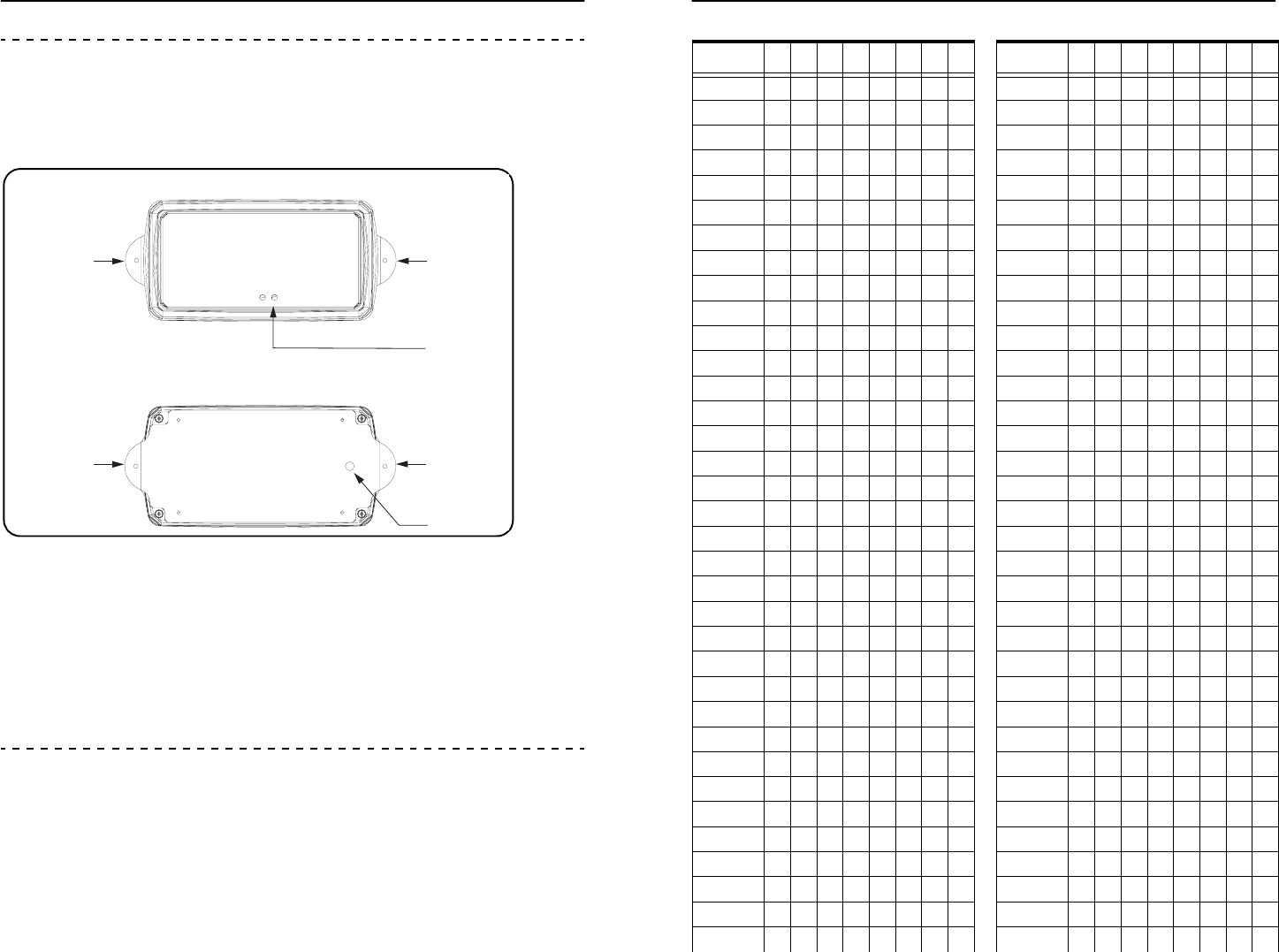
Top View
Exterior LEDs
Mounting EarMounting Ear
Bottom View
Mounting Ear
Mounting Ear
Wire Access
Page 3 981-000300-000 R1.00 (Draft)
105
106
107
108
109
110
111
112
113
114
115
116
117
118
119
120
121
122
123
124
125
126
127
128
129
130
131
132
133
134
135
136
137
138
139
Table 5: (Continued) Address Switch
Address
ABCDEFGH
140
141
142
143
144
145
146
147
148
149
150
151
152
153
154
155
156
157
158
159
160
161
162
163
164
165
166
167
168
169
170
171
172
173
174
Table 5: (Continued) Address Switch
Address
ABCDEFGH
Installation Guide: Proximity Tag Reader Installation Guide: Proximity Tag Reader
35
36
37
38
39
40
41
42
43
44
45
46
47
48
49
50
51
52
53
54
55
56
57
58
59
60
61
62
63
64
65
66
67
68
69
Table 5: (Continued) Address Switch
Address
ABCDEFGH
70
71
72
73
74
75
76
77
78
79
80
81
82
83
84
85
86
87
88
89
90
91
92
93
94
95
96
97
98
99
100
101
102
103
104
Table 5: (Continued) Address Switch
Address
ABCDEFGH
Proximity Tag Reader Location
Maximum Tag detection range is approximately 5 ft. (1.5 m). As a result, mount the PTR
very close to the tag detection location. For example, to detect a tag worn by someone
in a bed, wall mount the PTR at the head of the bed.
The PTR case was designed to make options and adjustments user-inaccessible. Unlike
other RFID devices, the PTR is designed for mounting in locations visible to the facility
occupants.
Setting LF Field Strength
Varying the LF field strength changes the size of the Tag detection zone.
Use Test Mode to set the LF Field Strength. Test Mode provides an audible beep; and,
disables network messaging.
Tools: You will need a VeriChip RFID Tag and a small common screwdriver.
To adjust the LF field strength:
1 Choose the PTR’s final mounting location.
2 Use the backplate to mark the wall.
3 Drill mounting holes in the wall.
4 Remove the PTR cover. Identify the Options Dip Switch as shown in Figure 2.
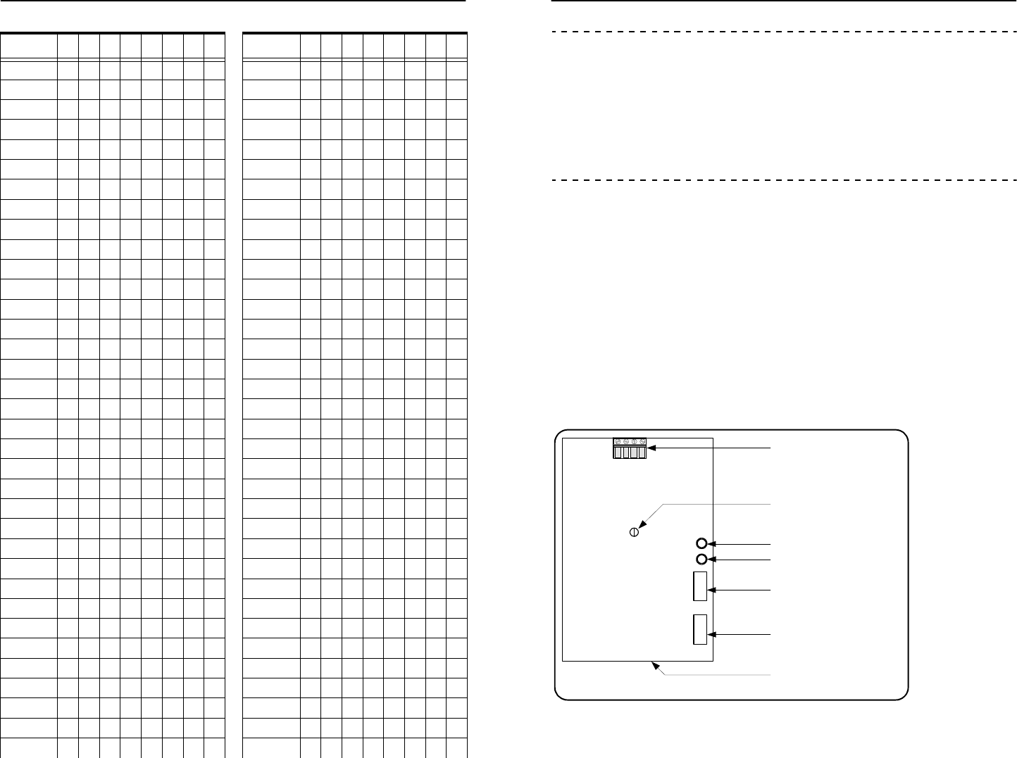
Figure 2: PTR Circuit Board
Page 4 981-000300-000 R1.00 (Draft)
4 Pin Wiring Connector for
Power and Optional Input
Green LED
Red LED
Address DIP Switch
Options DIP Switch
RF Field Strength
Adjustment
Proximity Tag
Reader Circuit Board
Installation Guide: Proximity Tag Reader Installation Guide: Proximity Tag Reader
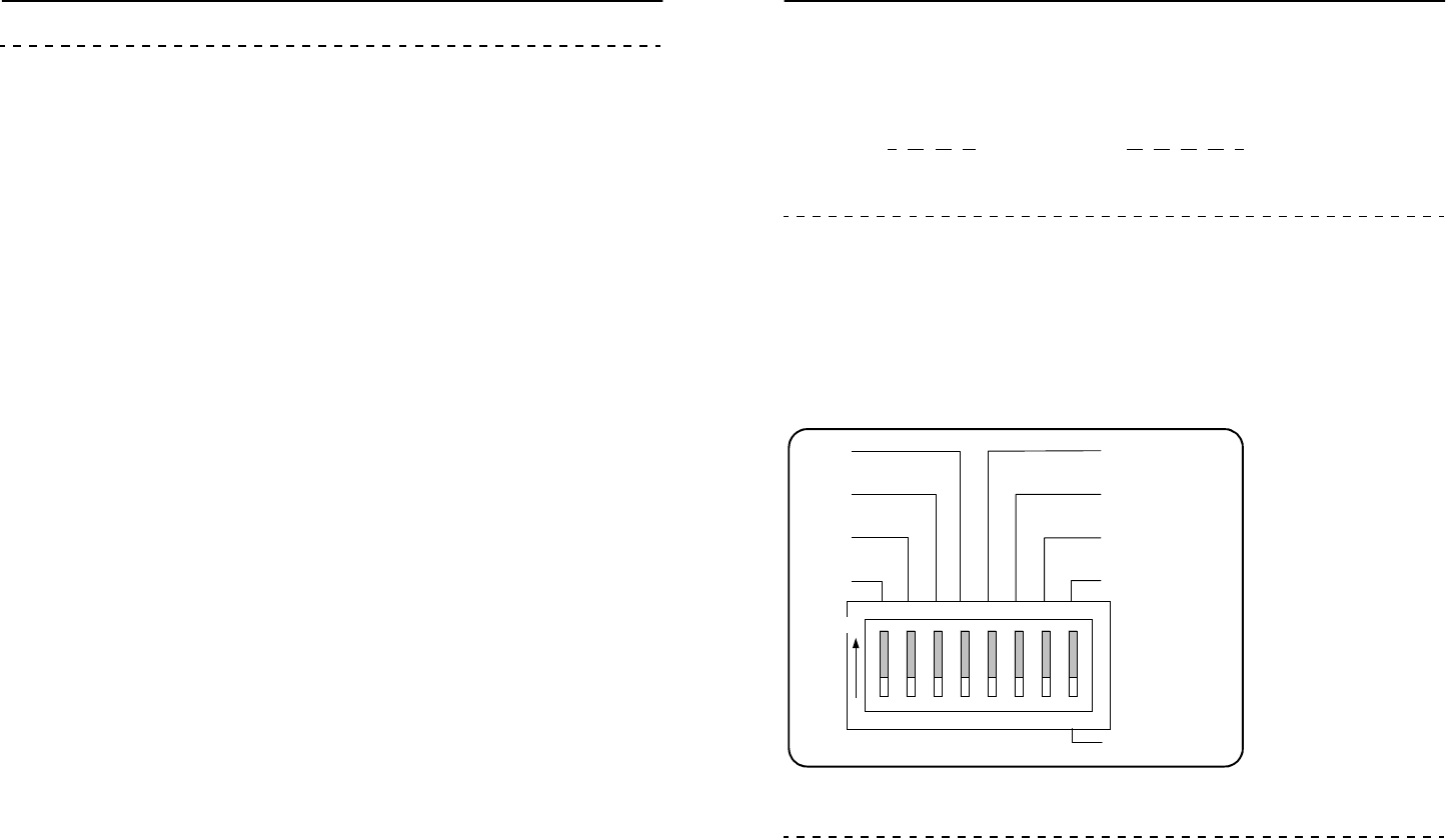
5 Use Figure 3 to identify the 3 Mode Switches: F, G, and H. Set all 3 Mode Switches to
0 as shown in Figure 3. This sets the PTR to Test Mode.
Figure 3: Mode Switches set in Test Mode
6 Temporarily mount the PTR in its final location and connect power as in Figure 4.
Figure 4: Power Wiring
7 Turn the LF field adjustment fully counter-clockwise. Do not turn the adjustment
forcefully to its limits. Do not needlessly wiggle or turn the adjustment.
8 Walk the tag to the detection area perimeter. Slowly turn the field adjustment
slightly clockwise. Stop turning when the red LED begins to blink.
9 Walk the Tag throughout the detection area to make sure that the LF field is
consistent throughout the area. If the LF field is inconsistent, turn the field
adjustment slightly counter-clockwise.
10 If you have increased the LF field strength, repeat Step 8 to ensure that the field
does not extend beyond the detection area.
Mode Switches
set to 0,0,0.
OPTIONS
Mode Switches
A B C D E F G H
ON
1 2 3 4 5 6 7 8
0 0 0
ON = 1
OFF = 0
+ 12 VDC
Ground
Input
Ground
Inputs are described
under “Standby Mode”
on Page 8.
Page 5 981-000300-000 R1.00 (Draft)
Appendix
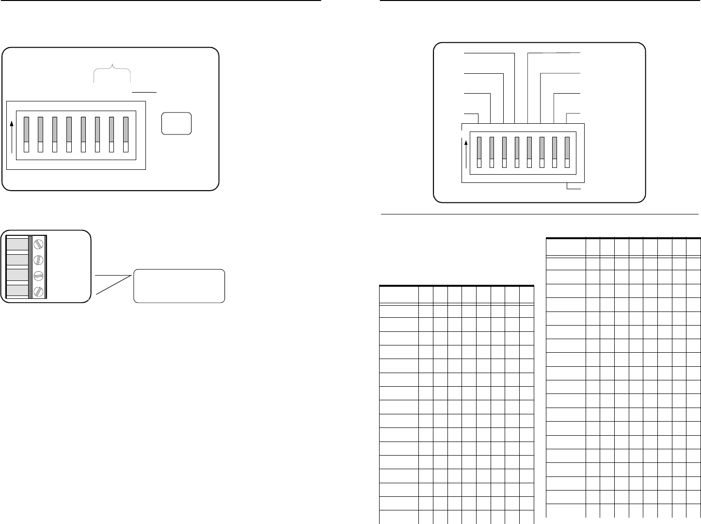
Figure 9: Address DIP Switch (Repeated for your convenience.)
In Table 5, the left hand column contains
the address. The columns, A – H, show
the switch positions: A black square
indicates the on position.
ADDRESS
ON
1 2 3 4 5 6 7 8
24 = 16
25 = 32
26 = 64
27 = 128
Least Significant Bit
A B C D E F G H
20 = 1
21= 2
22= 4
23= 8
Table 5: Address Switch Positions
Address
ABCDEFGH
0
1
2
3
4
5
6
7
8
9
10
11
12
13
14
15
16
17
18
19
20
21
22
23
24
25
26
27
28
29
30
31
32
33
34
Table 5: (Continued) Address Switch
Address
ABCDEFGH
Installation Guide: Proximity Tag Reader Installation Guide: Proximity Tag Reader
Specifications
General
Input Frequency . . . . . . . . . . . . . . . . . . . .434 MHz
Output Frequency . . . . . . . . . . . . . . . . . .307 kHz
Input Voltage . . . . . . . . . . . . . . . . . . . . . . .12 VDC at 300 mA
Detection Zone . . . . . . . . . . . . . . . . . . . . .1 ft. to 5 ft. (0.30 m to 1.5 m)
Additional Inputs/Outputs . . . . . . . . . .Dry Contact Input
Options
Operating Modes . . . . . . . . . . . . . . . . . . .Features 6 operating modes
Adjustable LF Field. . . . . . . . . . . . . . . . . .Allows adjustment of Tag Detection Zone to suit
application
Input . . . . . . . . . . . . . . . . . . . . . . . . . . . . . . .Input can be configured for EOL (security), and
normally open or normally closed switches
Addressable . . . . . . . . . . . . . . . . . . . . . . . .Addressable from 0 to 255
Network
LF Link. . . . . . . . . . . . . . . . . . . . . . . . . . . . . .Uses LF link to connect to security network.
Network wires NOT required.
Physical
Operating Temperature . . . . . . . . . . . . .32° F to 131° F (0° C to 55° C)
Storage Temperature . . . . . . . . . . . . . . .-22° F to 140° F (-30° C to 60° C)
Relative Humidity . . . . . . . . . . . . . . . . . . .90% non-condensing
Size
Power Supply . . . . . . . . . . . . . . . . . . . . . . .12 VDC regulated
Mounting. . . . . . . . . . . . . . . . . . . . . . . . . . .surface mount
Page 13 981-000300-000 R1.00 (Draft)
11 Turn off Test Mode by one of two methods:
Remove power.
Set the PTR to its usual operating mode. It is not necessary to remove
power to change operating modes. See Table 1 on page 8 for a list of
End of Procedure
operating modes and switch settings.
Setting the Address
Each PTR must have an address unique within its floor or facility. Addresses are entered
in binary format using the Address Dip Switch. The PTR can accept addresses ranging
from 0 to 255.
The least significant bit of the binary address is on the right hand side of the Address
DIP Switch. Figure 5 shows the binary value of every switch in the Address DIP Switch.
Table 5, appended to this guide, shows all address values and switch positions.
Figure 5: Address Dip Switch Showing Switch’s Binary Values
Selecting an Operating Mode
Operating modes are selected using the Mode Switches on the Options DIP Switch.
The location of the Options DIP Switch is shown Figure 2 on page 4.
Page 6 981-000300-000 R1.00 (Draft)
ADDRESS
ON
1 2 3 4 5 6 7 8
24 = 16
25 = 32
26 = 64
27 = 128
Least Significant Bit
A B C D E F G H
20 = 1
21= 2
22= 4
23= 8

Installation Guide: Proximity Tag Reader Installation Guide: Proximity Tag Reader
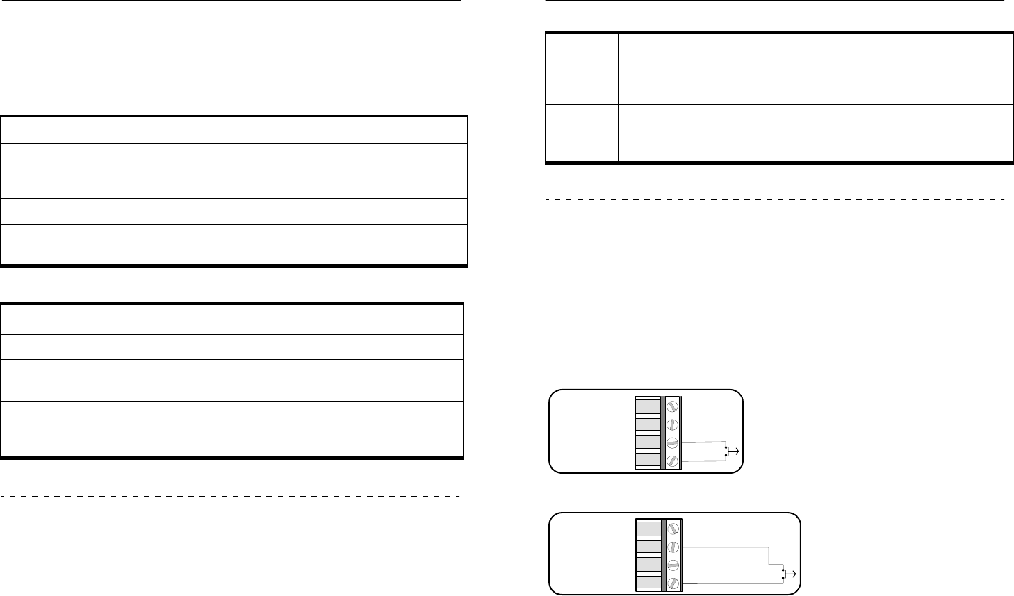
Figure 6: Mode Switches in the Options DIP Switch
Using Mode Switches to Select Operating Mode
Figure 6 shows the Options DIP switch and the nearby circuit board. The letters, A
through to H, are etched in the circuit board edge. The Mode Switches are labelled as
F, G, and H. Operating Modes are selected by the Mode Switches.
Table 1 lists the Mode Switches (F, G, and H) and the Operating Modes.
Figure 6 shows the Mode Switches set to Standby Mode.
Table 1: Operating Modes and Mode Switch Settings
Mode
Switches
Operating
Mode Description
FGH
0 0 0 Test Used for adjusting field size. Field is uninterrupted
and the PTR beeps at each tag identification.
Network messages are not sent.
0 0 1 Uninterrupted Field always on. Tags are identified as they enter the
field and queried once every 12 seconds. Tag
identities are re-acquired every minute.
0 1 0 Standby The PTR is active for 10 seconds when it is triggered
by an opening or closing contact. See Figure 6.
0 1 1 Duty Cycle 1 The LF field cycles on for 5 seconds and off for 30
seconds automatically. The PTR identifies and reports
any tags found while the field is on.
1 0 0 Duty Cycle 2 The LF field cycles on for 10 seconds and off for 5
minutes automatically. The PTR identifies and reports
any tags found while the field is on.
OPTIONS
Mode Switches
A B C D E F G H
ON 1 2 3 4 5 6 7 8
Mode Switches are
set to 0,1, 0, which is
Standby Mode.
0 01
Page 7 981-000300-000 R1.00 (Draft)
Troubleshooting
When the PTR detects an error condition it will do all of the following:
Transmit an error message to the network; and,
Flash the red LED in a repeating pattern of 12 short flashes and one long flash; and,
Sound the buzzer every 12 flashes.
The PTR may enter an error state for three reasons:
An invalid combination of configuration switches has been set. For example,
setting the Mode Switches to 1, 1, 0 or 1,1,1 will cause an error.
The EOL input is not returning the correct measured value. This could be treated as
a tamper alarm. If it is not a tamper alarm, then correct the EOL resistor value or
move DIP Switch B to off.
The main supply voltage is low. If the PTR can still function with the low supply
voltage the device will continue to report tags while in the error state. If the
voltage supply is so low that the PTR cannot function, it will enter the Low Power
Mode which is described in the preceding text.
In each of the three error states, the PTR transmits a network message that indicates
which of the three causes is responsible.
Page 12 981-000300-000 R1.00 (Draft)
Installation Guide: Proximity Tag Reader Installation Guide: Proximity Tag Reader
Verifying Operation
Verify the operation of the PTR by observing the two LEDs. During Test Mode, listen for
the buzzer to indicate Tag detection. Table 3 and Table 4 list the LED and buzzer
signals and the corresponding operations and states.
Low Power Mode
If main power fails the PTR will enter Low Power Mode.
Low power mode is indicated by the following:
The green LED is off; and,
The red LED is flashing approximately once every 1.5 seconds.
In low power mode the PTR does not generate a LF field. The PTR transmits a “Device
in Low Power Mode” message to the network approximately once every 12 seconds.
The PTR remains in this mode until main power is restored or until reserve power is
exhausted. Reserve power should last for at least 15 minutes. When main power is
restored the PTR will begin normal operation.
Table 3: Power and LF Field States
LED and Buzzer Power and LF Field State
Buzzer emits short beep. Power up.
Green LED slowly flashing. Power on and LF field off.
Green LED on continually. Power on and LF field on.
Red LED briefly flashes once
every 1.5 seconds.
Main power has been lost. See Low Power
Mode on page 9.
Table 4: Tag Identification Operations
LED and Buzzer Operation
Red LED flashes Tag identified, network message sent.
Red LED flashes with buzzer beep Test Mode tag identification. A network
message is NOT sent.
Red LED continually emitting brief
flashes. Every 12 seconds, a longer red
LED flash occurs and the buzzer beeps.
Error: The PTR has detected one of three
error conditions. See “Troubleshooting”
on page 8.
Page 11 981-000300-000 R1.00 (Draft)
Standby Mode
In Standby Mode the LF field is triggered on for 10 seconds when the input contacts
are opened or closed. The PTR identifies and reports tags while the LF field is on. After
10 seconds the LF field shuts down until the next input trigger.
Select Standby Mode by setting the Mode Switches to 0, 1, 0 as in Figure 6.
Input Wiring
The input is an active low so that when the input terminal is grounded the input is
active or on. Wire the input to one terminal of a switch. Wire the other side of the
switch to either ground terminal on the PTR 4 pin wiring connector.
Figure 7: Input Wiring
Figure 8: Alternate Input Wiring
End Of Line Input in Standby Mode
The End-Of-Line (EOL) setting enables input fault or input tampering detection.
An EOL input provides two fixed resistance values instead of open and closed switch
states. The PTR will treat the transition from one resistance value to the other as an
opening, or as a closing switch. If EOL resistors are installed and the EOL input is
enabled, the PTR will remember the input values resulting from the EOL resistors.
1 0 1 Duty Cycle 3 The LF field cycles on for 10 seconds and off for 30
minutes automatically. The PTR identifies and reports
any tags found while the field is on.
Table 1: (Continued)Operating Modes and Mode Switch Settings
Mode
Switches
Operating
Mode Description
FGH
Page 8 981-000300-000 R1.00 (Draft)
+ 12 VDC
Ground
Input (Active Low)
Ground
+ 12 VDC
Ground
Input (Active Low)
Ground
Installation Guide: Proximity Tag Reader Installation Guide: Proximity Tag Reader
Installation
To install the PTR:
1 Select a location remembering that the detection zone is limited.
2 Use the PTR backplate as a template for locating mounting holes.
3 Drill a hole in the wall for the power wire. Route the power wire inside the wall in
accordance with the local wiring regulations in your district.
4Open the PTR case.
5 Push the power wire through the PTR backplate and work it towards the wiring
connector.
6 Connect the power wires as in Figure 8.
7 Optionally, connect the input wires as in Figure 8.
8 Set the PTR to Test Mode by setting the Mode Switches to 0, 0, 0. Mode Switches
are part of the Options DIP Switch and are shown in Figure 6.
9 Temporarily mount the PTR in its final location. Do not close the case.
10 Adjust the LF field. See “Setting LF Field Strength” on page 4.
11 Set the PTR address, and normal operating mode. See “Selecting an Operating
Mode” on page 5 and Table 1 on page 8.
12 Record the PTR address and location for later inclusion on the floor plan.
13 Close the enclosure.
14 Using the holes provided in the backplate, mount the PTR in its location. Use
fasteners such as screws or wall anchors so that, if required, the device can be
End of Procedure
removed from the wall, re-configured, and replaced in the same location.
Figure 8: 4 Pin Terminal Block Wiring
(Repeated for your convenience)
+ 12 VDC
Ground
Input
Ground
Page 10 981-000300-000 R1.00 (Draft)
If the PTR detects an input value different from the EOL values, it will respond as for an
error. Please see “Troubleshooting” on page 9.
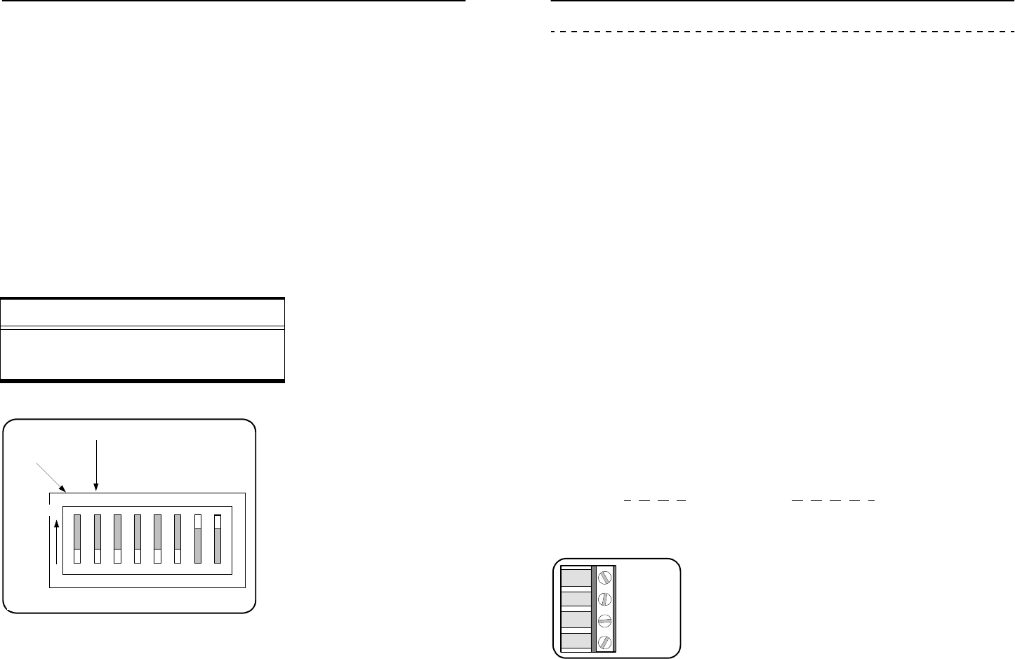
To enable an EOL input, turn Switch A of the Options DIP switch on. See Figure 7.
Edge Select in Standby Mode
Edge section is controlled by switch B in the Options DIP Switch shown in Figure 7.
Turn Switch B on to trigger the LF field on when:
the switch opens; or,
when a normally closed (NC) relay opens.
Turn Switch B off to trigger the LF Field on when:
the switch closes; or,
when a normally open (NO) relay closes.
These conditions are summarized in Table 2.
Figure 7: EOL and Edge Selection Switches
Table 2: Setting the LF Field Trigger
Switch Relay LF Field Switch B
Opens NC opens Turns on On
Closes NO closes Turns on Off
Page 9 981-000300-000 R1.00 (Draft)
EOL Switch
Edge Selection Switch
OPTIONS
ON
1 2 3 4 5 6 7 8
A B C D E F G H