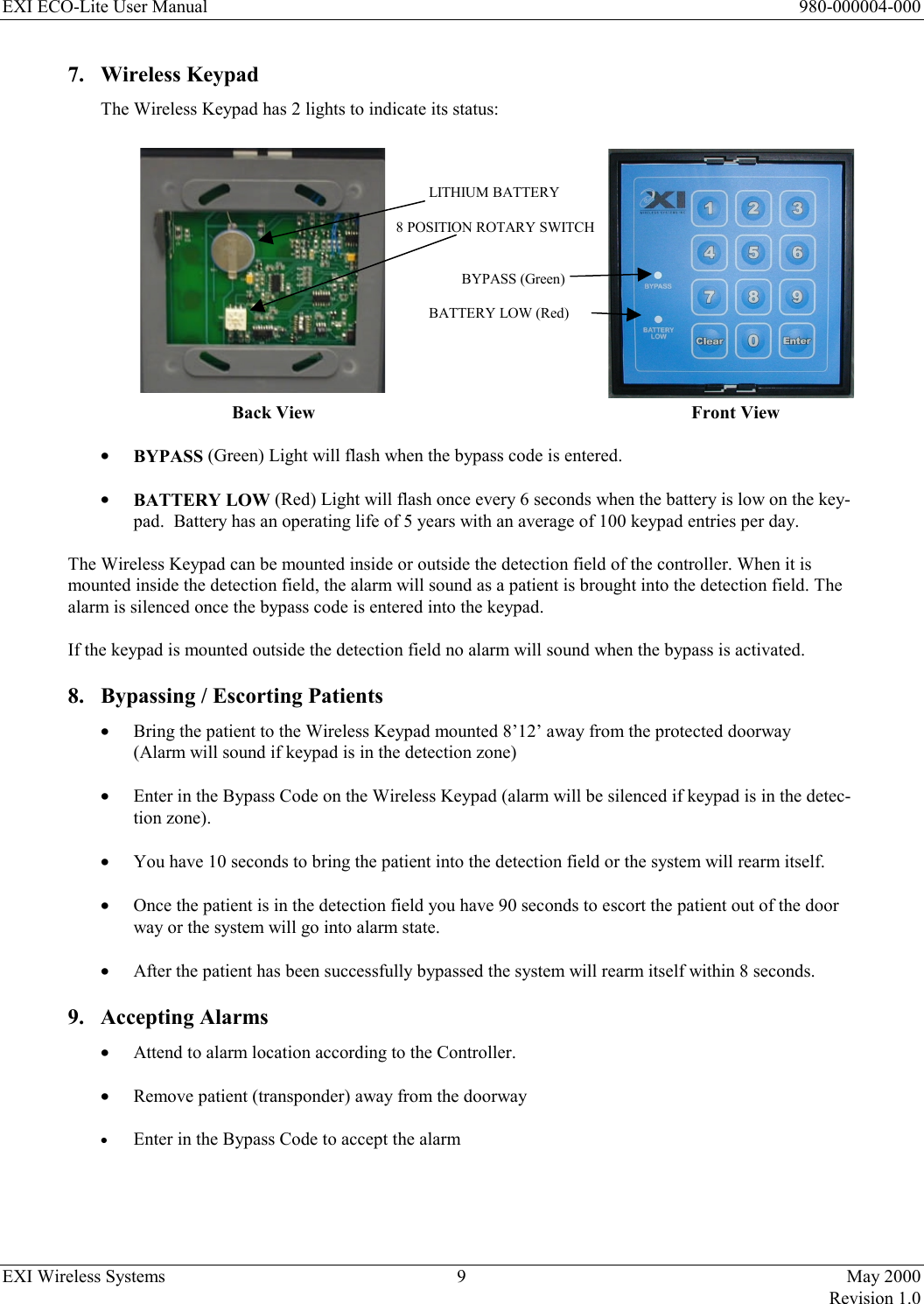
Xmark WKP Wireless Keypad User Manual Limited Warranty

Xmark Corporation Wireless Keypad Limited Warranty

Users manual

Revision 1.0        Installation & User Manual     May 2000         © Copyright 2000, EXI Wireless Systems Inc. All rights reserved.
EXI ECO-Lite User Manual      980-000004-000 EXI Wireless Systems  2  May 2000   Revision 1.0    Table of Contents   1. Limited Warranty.................................................................................................................................. 3 2. Record of Changes................................................................................................................................ 4 3. FCC Regulations................................................................................................................................... 5 4. Introduction........................................................................................................................................... 6 5. Initializing the ECO-Lite System .......................................................................................................... 7 6. ECO-Lite Controller ............................................................................................................................. 8 7. Wireless Keypad ................................................................................................................................... 9 8. Bypassing / Escorting Patients .............................................................................................................. 9 9. Accepting Alarms ................................................................................................................................. 9 10. Password Management.................................................................................................................... 10 10.1. Master Password ..................................................................................................................... 10 10.2. User password......................................................................................................................... 10 11. Operational Mode Change .............................................................................................................. 11 12. System Settings ............................................................................................................................... 11 12.1. Test Mode “51”....................................................................................................................... 11 12.2. Normal Mode with fixed alarm duration “52” ........................................................................ 11 12.3. Normal Mode with unlimited alarm duration “53” ................................................................. 11 13. Assigning the Keypad to the Controller ..........................................................................................12 14. Tamper Alarm................................................................................................................................. 12 15. Wrist Tags....................................................................................................................................... 12 16. Power Supply.................................................................................................................................. 12 17. Controller Enclosure ....................................................................................................................... 13 18. Wireless Keypad Enclosure ............................................................................................................ 13
EXI ECO-Lite User Manual      980-000004-000 EXI Wireless Systems  3  May 2000   Revision 1.0   1. Limited Warranty  EXI Wireless Systems Inc. (“EXI”) hereby warrants the product(s) accompanying this limited warranty (the “Product(s)”) to be free of defects in materials and workmanship for a period of two years (excluding any batteries that may be added to or used in conjunction with the Products(s)) from the date of delivery of the original purchase of the Product(s) subject to the limiting conditions set forth below, provided that EXI has received notification of such defects no later than 30 days after expiration of the applicable warranty period and provided further that EXI has received a fully completed registration card (below) within 30 days from the date of original purchase of the Product(s). The responsibility of EXI under this warranty is and shall be limited to repairing or replacing the Product(s) or any part thereof determined by EXI in its sole discretion to be defective in workmanship or material. The installation of the Product(s) shall be deemed as acceptance by the original purchaser and any subsequent purchaser of the Product(s) (collectively the “Purchaser”) of the terms set out in this limited warranty including the following further limiting conditions: (a)  EXI shall not be responsible for any repair or replacement of any Product(s) which has been found, upon inspection, to have been subjected to abuse, misuse or negligence, or any damage attributable to accident, lightning, power surge, brown-out, leaking, damaged or inoperative batteries or to have been installed, altered or repaired contrary to factory designated procedures without the prior written consent of EXI; (b)  It is understood, and the Purchaser agrees further to so inform any user of the Product(s) that the Product(s) is not, nor can it be, infallible in the detection of wandering patients, the prevention of infant abduction, the prevention of theft of assets or any other contemplated use of the Product(s).  The Purchaser will warn all users and acknowledges on it’s own behalf that it has read and understands the above-mentioned limitations of the Product(s).  The Purchaser further acknowledges that the Product(s) are solely intended to provide an additional safeguard in notifying staff and accordingly do not guarantee the prevention of wandering patients or the attempted abduction of an infant or the theft of assets; (c)  It is further agreed by the Purchaser that the Purchaser has received no additional promises or statements of fact from EXI or its agents relative to the Product(s) upon which the Purchaser might have relied in purchasing the Product(s); (d)  The warranty set out above excludes and is in lieu of all other express or implied warranties, conditions or obligations, and no person is authorized to give any further representation or warranty or assume any further obligation on behalf of EXI.  Although the Purchaser may have other rights, as they may vary from State to State or Province to Province, where it is legally possible to do so any statutory warranty is hereby expressly excluded.  The warranty is subject to the domestic laws of Canada and the Purchaser agrees to attorn to the jurisdiction of the courts of competent jurisdiction in the Province. (e)  EXI shall not be liable for any damages, whether direct or, indirect, incidental, consequential or arising out of contact or tort with the sole exception of the warranty set out above and any rights expressly created by applicable statute.  THIS WARRANTY IS VALID ONLY IN THE USA AND CANADA
EXI ECO-Lite User Manual      980-000004-000 EXI Wireless Systems  4  May 2000   Revision 1.0  2.  Record of Changes  May 2000    Revision 1.0     Initial Release
EXI ECO-Lite User Manual      980-000004-000 EXI Wireless Systems  5  May 2000   Revision 1.0   3. FCC Regulations  This device complies with Part 15 of the FCC Rules.  Operation is subject to the following two conditions:  (1) This device may not cause harmful interference, and (2) This device must accept any interference re-ceived, including interference that may cause undesired operation.   EXI Wireless Systems  Model No.: ECO-Lite Controller CANADA  FCC ID: HE7 ELC *  This device complies with Part 15 of the FCC Rules.  Operation is subject to the following two rules: (1) This device may not cause harmful interference, and (2) This device must accept any interference received, including interference that may cause undesired operation. Made in Canada  EXI Wireless Systems  Model No.: Wireless Keypad CANADA  FCC ID: HE7 WKP *  This device complies with Part 15 of the FCC Rules.  Operation is subject to the following two rules: (1) This device may not cause harmful interference, and (2) This device must accept any interference received, including interference that may cause undesired operation. Made in Canada
EXI ECO-Lite User Manual      980-000004-000 EXI Wireless Systems  6  May 2000   Revision 1.0  4. Introduction ECO-Lite is a long range proximity detection device usually used as a departure alarm. ECO-Lite detects the presence of EXI wrist or asset transponders within a prescribed detection zone. ECO-Lite may be used to: •  Alert if people of property at risk are near an egress or danger zone. •  Automatically open doors or activate equipment when a tag is present. •  Indicate proximity of any "tagged" item or person.  ECO-Lite is simple to install and uses EXI's high reliability RFID (Radio Frequency Identification) proto-cols to ensure accurate detection.  A wrist tag is sensed when it enters a detection field that is set up around the EXI ECO-Lite Controller. This system uses a wireless keypad to control bypass functions, accepting alarms and changing passwords.  ECO-Lite is a valued priced system designed to be used as a stand alone or networked system to protect smaller perimeters.  Various features are built in the ECO-Lite System to accommodate for all possible applications with mini-mum supervision.   •  Adjustable detection range (3’-12’) •  Bypass alarms •  Audio and visual alarm indication  •  1 Master password •  2 Users passwords •  Remote Wireless Keypad •  Light weight Wrist Tag with a 4-year pro-rated warranty •  +24V DC wall adapter power supply •  Auxiliary Port: 1set of NO / NC relay contacts   ECO-Lite is designed to assist staff in providing a higher degree of safety for patients. It is not intended as the sole means of protection in preventing a wanderer or infant from leaving the premises. Regular checks to verify that your ECO-Lite system is operational is highly recommended.
EXI ECO-Lite User Manual      980-000004-000 EXI Wireless Systems  7  May 2000   Revision 1.0   5.  Initializing the ECO-Lite System Before using the ECO-Lite System, the wireless keypad must be configured to communicate with the con-troller.  The following procedure follows:  1.  Plug in the 24V AC adapter into the controller power jack. 2.  Preset the rotary switch SW100 on the controller to match the keypad (position 0-7).  3.  Type Master password (9876- Factory Default) on keypad and then press the ‘Enter’ key. (The green bypass led should blink on the keypad) 4.  Type number (1) on the keypad. 5.  Press ‘Enter’ key. 6.  Press ‘Clear’ key. (Hear a short beep) 7.  Type Master password (9876 - Factory Default) on keypad and then press the ‘Enter key’. 8.  Enter number (1) on keypad and press the ‘Enter’ key. 9.  Type in a 4-digit code ”XXXX” and press the ‘Enter’ key.  (Hear 2 short beeps)                    The controller should now be configured to communicate with the keypad.   To confirm, retype the 4-digit code on keypad and press ‘Enter’ key.   You should hear an alarm accompanied by alternating red and the yellow LEDs.    If no alarm, then repeat the configuration process, ensuring that the keys are pressed properly each time you enter a number.   After the controller has been configured, each time that you enter the 4-digit code, a low tone alarm should go off and you should see alternating red and yellow LEDs on the controller.   Rechargeable Back-up Battery Switch  Shipped from the factory in the “OFF” position. Turn both switches to the “ON” position to activate the rechargeable back up battery supply in case of a power failure.
EXI ECO-Lite User Manual      980-000004-000 EXI Wireless Systems  8  May 2000   Revision 1.0  6. ECO-Lite Controller The ECO-Lite has 3 lights to indicate status:     Green       Yellow        Red (Standby)   (Bypass)   (Alarm)           Front View  •  “GREEN LIGHT” indicates the power is on and the system is on standby.  •  “RED LIGHT” FLASHING indicates an alarm is in progress (tag detected in range). •  “YELLOW LIGHT” & “RED LIGHT” alternately FLASHING indicates the system is in   BYPASS Mode.          Back View                                               Side View          8 Position rotary switch use to set the ID address between the keypad and controller. Auxiliary Port: 1 set of N/O & N/C relay contacts to drive external devices. (cameras, sounders, magnetic locks) Potentiometer used to adjust the field detection zone (3’-12’)  Maximum: Fully Clockwise Input power from wall mount adapter 24V @ 500mA Back-up battery switches. Shipped in OFF position. Turn both switches ON to activate back up battery supply.
EXI ECO-Lite User Manual      980-000004-000 EXI Wireless Systems  9  May 2000   Revision 1.0  7.  Wireless Keypad  The Wireless Keypad has 2 lights to indicate its status:               LITHIUM BATTERY            8 POSITION ROTARY SWITCH   BYPASS (Green)     BATTERY LOW (Red)        Back View            Front View  •  BYPASS (Green) Light will flash when the bypass code is entered.  •  BATTERY LOW (Red) Light will flash once every 6 seconds when the battery is low on the key-pad.  Battery has an operating life of 5 years with an average of 100 keypad entries per day.  The Wireless Keypad can be mounted inside or outside the detection field of the controller. When it is mounted inside the detection field, the alarm will sound as a patient is brought into the detection field. The alarm is silenced once the bypass code is entered into the keypad.  If the keypad is mounted outside the detection field no alarm will sound when the bypass is activated. 8.  Bypassing / Escorting Patients •  Bring the patient to the Wireless Keypad mounted 8’12’ away from the protected doorway  (Alarm will sound if keypad is in the detection zone)  •  Enter in the Bypass Code on the Wireless Keypad (alarm will be silenced if keypad is in the detec-tion zone).  •  You have 10 seconds to bring the patient into the detection field or the system will rearm itself.  •  Once the patient is in the detection field you have 90 seconds to escort the patient out of the door way or the system will go into alarm state.  •  After the patient has been successfully bypassed the system will rearm itself within 8 seconds.     9. Accepting Alarms •  Attend to alarm location according to the Controller.  •  Remove patient (transponder) away from the doorway  •  Enter in the Bypass Code to accept the alarm
EXI ECO-Lite User Manual      980-000004-000 EXI Wireless Systems  10  May 2000   Revision 1.0  10. Password Management There are two types of passwords: Master password and User password. Master password is used to assign or delete User password. User passwords are used to bypass the system.   There is only one Master password and 2 user passwords. All passwords are 4 digit numbers.  10.1. Master Password This password is used to change or delete User password or to change itself (Master password). To change Master Password:  1. Enter existing Master password 2. Press ‘ENTER’ key 3. Enter existing Master password again 4. Press ‘ENTER’ key 5. Enter new 4 digit Master password (not less then 4 digits) 6. Press ‘ENTER’ key 7. After this the keypad Bypass light will flash 3 times and Controller buzzer will beep 4 times to             indicate that new Master password is accepted by both, the Keypad and the Controller. 10.2. User password This password is used to bypass the system and to silence the alarms.  To change/add User password:  1. Enter Master Password 2. Press ‘ENTER’ key 3. Enter password slot number (1 or 2) 4. Press ‘ENTER’ key 5. Enter new 4 digit User password (not less then 4 digits) 6. Press ‘ENTER’ key  After this the keypad Bypass light will flash 3 times and Controller buzzer will beep 2 times to indicate that new User password is accepted by both, the Keypad and the Controller.  To delete User Password:  1. Enter Master Password 2. Press ‘ENTER’ key 3. Enter password slot number (1 or 2) 4. Press ‘ENTER’ key 5. Press ‘CLEAR’ key  After this the keypad Bypass light will flash 3 times and Controller buzzer will beep 1 long beep indicate that one of the User passwords is deleted by both, the Keypad and the Controller.
EXI ECO-Lite User Manual      980-000004-000 EXI Wireless Systems  11  May 2000   Revision 1.0  11.  Operational Mode Change To change the operation mode: 1. Enter Master Password 2. Press ‘ENTER’ key 3. Enter code for mode of operation: •  “51”   Test Mode •  “52”  Normal Mode with Unlimited Alarm Duration •  “53’   Normal Mode with Fixed Alarm Duration 4. Press ‘ENTER’ key  When the code is entered, the Controller will beep a distinctive number times for each different mode:   •  Once for Test Mode •  Twice for Fixed Alarm Duration Mode and •  Three times for Unlimited Alarm Duration 12. System Settings There are three modes of operation available to the user or installer: 12.1.  Test Mode “51” In this mode the system does not generate any alarms. This mode is used to setup the field strength and position the controller properly. When a tag is in the field the controller will beep briefly.  Test mode will terminate after 30 seconds if the controller does not detect a tag in the field. 12.2.  Normal Mode with fixed alarm duration “52” This is default operational mode in which the alarm will terminate after 20 seconds the tag is out of the field. 12.3.  Normal Mode with unlimited alarm duration “53” In this mode the alarm will not end until the password is entered (system bypassed).
EXI ECO-Lite User Manual      980-000004-000 EXI Wireless Systems  12  May 2000   Revision 1.0  13.  Assigning the Keypad to the Controller The Keypad can only communicate to the Controller if they both have the same ID number. Each Keypad and Controller comes with 8-position rotary switch, which is used to set this ID number. Multiple Control-lers could be programmed to respond to the same Keypad or multiple Keypads could be used to send com-mands to the same Controller (their ID settings should be the same). When the Keypad and Controller are shipped from the factory, they all have ID number set to ‘2’ so every Keypad can communicate with every Controller. The installer needs to change this only if multiple Controllers and Keypads interfere with each other.    Rotary Switch found on the back of the Wireless Keypad and the Controller.         14. Tamper Alarm The keypad is protected with the tamper switch installed at the back to prevent unauthorized removal. When this switch is released, the keypad sends the message to the Controller signaling tamper alarm and the Con-troller goes into the alarm mode. This alarm can be silence by entering the password. 15. Wrist Tags Also referred to as “Tags”, these devices are attached to the patient. Wrist tags initiate alarm conditions when it enters an area protected by a Controller. The Controller emits a constant field of radio waves, which is picked up by the Tag when in the proximity of the Controller. The Tag reports its presence to the Con-troller when it senses this RF field.   16. Power Supply The Controller is powered by a 24V DC / 500mA external wall adapter power supply.  The Controller also has a rechargeable backup battery to provide power for the processor for 1 hour or until power is restored in case of an emergency where the main power supply is cut off.  During this time the  audible alarm is generated at the controller which can be muted by the entering the bypass code at the wire-less keypad.   The Wireless Keypad is powered by a lithium battery at 3V / 220 mA.  The battery should last for at least 5 years with average of 100 keypad entries per day.  When the battery is low on the keypad the “Battery Low” RED light will flash once every  6 seconds, and the Controller buzzer will give a low tone beep at the same time.  The battery is easily replaceable by opening the enclosure from the front.
EXI ECO-Lite User Manual      980-000004-000 EXI Wireless Systems  13  May 2000   Revision 1.0  17. Controller Enclosure The best position for this Controller is to be installed above the door (best field coverage).  The controller is mounted to the wall by two mounting tabs.    18.  Wireless Keypad Enclosure The base plate of the keypad is mounted to the wall with 4 screws and the keypad face plate simply snaps onto this base plate. The best position to mount the keypad is usually 8’-12’ away from the protected door-way.  Wireless Keypad  WALLBASEPLATEBACKPLATEBEZEL

Navigation menu