Xmark XLX Large Exciter User Manual 805U6201 Rev B indd
Xmark Corporation Large Exciter 805U6201 Rev B indd
Xmark >
Users Manual
Large Exciter Instructions
Part Number 805A6201
309 Legget Drive, Ottawa, ON K2K 3A3, Canada or
808 Commerce Park Drive, Ogdensburg, NY 13669 USA
Telephone: 1-613-592-4642 Facsimile: 1-613-592-4296 Web Site: www.xmarksystems.com
© 2002 Instantel Inc. All Rights Reserved. Instantel and Hugs are registered trademarks of
Instantel Inc. in North America. The hearts logo and Xmark are trademarks of Instantel Inc. Xmark
is a division of Instantel Inc. Printed in Canada. November 2002. 805U6201 Rev B.
Certifi ed to the ISO 9001 Quality Standard
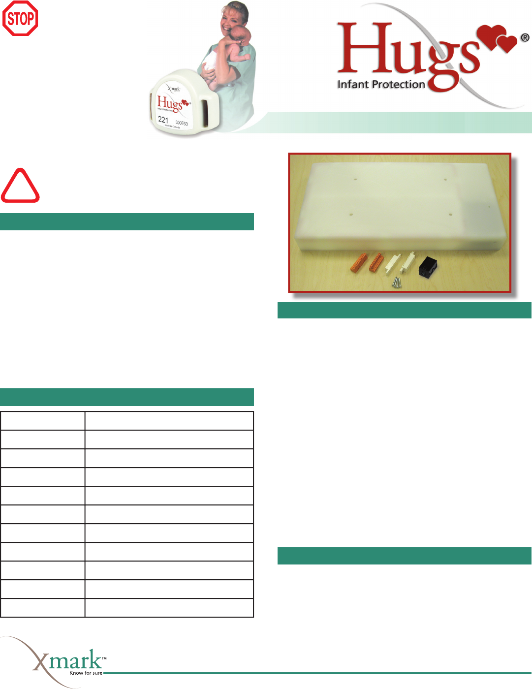
Materials Required
• Exciter. Includes door contact, ferrite core (p/n 28A2029-0A2)
and terminal blocks.
• Facility fl oor plan indicating Exciter position and installation
orientation, and network wiring path.
• 105 Ω network terminator (p/n 805A2401) required to terminate
network. Two provided with each Controller (p/n 805A2201) or
Laptop Controller (p/n 805A2202).
• Suitable mounting hardware, such as wall anchors
• Optional: Passive infrared sensor for open doorways where door
contact cannot be used. Refer to Chapter 2 of the Hugs Instal-
lation Manual (p/n 805I0301) for important limitations on
using PIR sensors.
Specifi cations
Read these instructions thoroughly
before installing the Exciter.
Faulty installation can lead to system failure.
!
Installation Considerations
• Avoid metal—Do not install the Exciter behind or within 2
inches (50 mm) of metal objects, including metal doors. These
objects block the detection area of the Exciter.
• Use door contacts—Door contacts are required to minimize
nuisance alarms.
• Confi gure nearby Exciters as slaves—Exciters installed within
30 feet (9 m) of each other must be confi gured as master and
slave. Up to four slaves may be connected to one master.
• Use the supplied ferrite core—Wrap the power cable around the
supplied ferrite core, as explained in the instructions. Failure to
do so will void the user’s authority to operate the equipment.
• Observe temperature and humidity restrictions—Refer to the
Specifi cations table.
• Leave slack in the cable—Leave at least 10 ft. (3 m) of slack in
the communication and power cable to allow for adjustments in
the location of the Exciter.
• No user adjustments to internal circuitry—Tampering may
cause component or system failure, or both, and will void the
warranty.
Important Reference Documents
• Hugs Installation Manual (p/n 805I0301)
Refer to Chapter 2 of the Hugs Installation Manual for
detailed information on detection areas, installation options,
master/slave confi gurations and software settings.
• Hugs System Manual (p/n 805U1601)
• Exciter Tester Sheet (p/n 805U2101)
Materials Required
Specifi cations
Installation Considerations
Important Reference Documents
Have
you:
• Pulled network and
power cable?
• Resolved power supply
requirements?
• Selected Exciter orientation
and position?
If you answered, “No,” to any
of these questions, refer to
the Hugs Installation Manual
before installing.
Frequency 312.5 kHz
Supply 10-30 VDC
Current Draw 200 mA @ 24 VDC, 800 mA maximum
Relay Outputs (2) 30 VDC, 1 A, NO or NC
Detection radius Adjustable, up to 11 ft.
Communications LonWorks two-wire
Temperature - operating 32° to 122° F (0° to 50° C)
Temperature - storage -40° to 176° F (-40° to 80° C)
Humidity 0 - 90% RH @ 70° F (21° C)
Dimensions Approx 20.7 x 10.9 x 2.3 in. (526 x 275 x 60 mm)
Weight Approximately 6 lbs. (2.7 kg)
Installing the Exciter
• Ensure that the power supply and network are turned
off to prevent electrical shock or damage to equip-
ment.
• Touch your hand to ground to discharge any electro-
static charge before handling the Exciter.
1 Locate and record the LonWorks identifi cation number onto the
facility fl oor plan indicating the Exciter’s position and network
wiring path. Use the tear-away sticker on the Exciter’s Neuron
ID label.
2 Install the supplied door contact or PIR sensor according to the
manufacturer’s instructions and connect it to the terminal, as
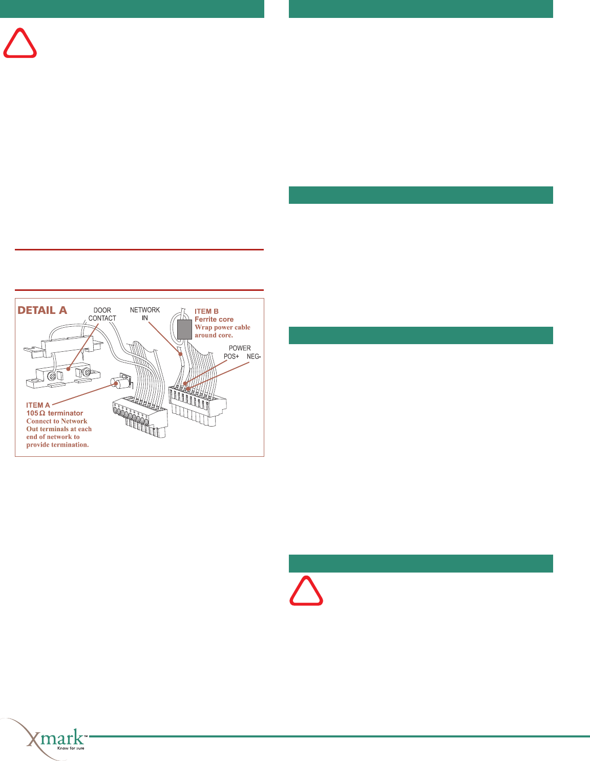
shown in the wiring diagrams. Connect the LonWorks Network
IN, Network OUT, and Power Supply to the terminal blocks,
as shown in the wiring diagrams. Wrap the Power Supply cable
around Item B (ferrite core); DO NOT use substitutes.
If the Exciter is at the end of the network, then terminate the net-
work segment with Item A (105 Ω terminator). Refer to Figure
1, and insert the terminals into the connectors on the Exciter.
Note: If installing keypads or accessory devices, or if using a
master/slave confi guration, proceed to the relevant sections on
the opposite page, and then return to steps 3 and 4.
3 Ensure that the status LED of the Exciter (located on the bottom
of the case) will be visible. Refer to the facility fl oor plan for
location, and using the Exciter as a template mark the location
of the four mounting holes. Drill the holes.
4 Mount the Exciter:
A Install in the four mounting holes:
4 hollow wall anchors
B Insert into the wall anchors, leaving 3/8 in. (0.5 cm) of the
shaft exposed:
4 No. 12 wood screws x 2 in. long
C If using surface wire conduit, attach the four supplied
bumpons (Item B in Figure 1) to the underside of the
Exciter.
D Align the Exciter with the mounting screws, and while lightly
pressing, slide until it is securely in place. Insert the supplied
screw caps.
Installation is complete. Proceed to Final Steps below.
!
Installing Keypads
Refer to the wiring diagrams below and the manufacturer’s instructions.
Keypads may be connected to either master or slave Exciter.
Notes:
• Either one Wiegand or two Corby keypads can be connected to
an Exciter.
• The Wiegand and Corby keypads cannot be connected to the same
Exciter.
• The Wiegand keypad requires a 12 VDC power supply; set the
central Power Supply to 12 V for this application.
• Corby keypads may be powered at 12 or 24 VDC. If connected at
24 V, they require a 1 kW, 1/4 Ω resistor connected between the
power supply and each keypad LED. Refer to Figure 2 below.
Installing Accessory Devices
Each Exciter has two 30 VDC, 1 Amp, NO or NC relays for con-
trolling accessory devices, such as magnetic door locks and high
output alarms.
Refer to the wiring diagrams and the manufacturer’s instructions for
installation procedures. Devices may be connected to either master
or slave Exciters; connect devices to the master Exciter’s relays fi rst,
then connect additional devices to the slave Exciter, starting with
the closest.
Note: Accessory devices require their own power supply.
Master/Slave Installations
Master and slave Exciters are installed and connected to the Lon-
Works network in the same way as other Exciters, with the following
additions:
• All Exciters in master/slave group are connected in series through
their M/S and ground terminals using 20 AWG wire, as shown
in the wiring diagrams.
For slave Exciters using their own ID numbers, the following is also
required, as shown in Figure 2:
• The mag lock (or elevator hold) outputs are wired to the relays
on both the master and the slave to ensure that all doors in the
vicinity will lock when a tag is present.
• Door contacts are wired together in series to the door contact
input on both the master and the slave. The result is that when
any door in a master/slave confi guration is open, the system
behaves as if all doors are open: an alarm will occur if a tag is at
a door in the vicinity of a door that is open.
Final Steps
Do not supply power to the Exciter or any other network
device until all connections are complete.
Once all devices are installed, power up the Exciter and other devices.
In the Xmark software, run Auto Confi gure to install the new devices,
and then confi gure them for operation.
The coverage area of each Exciter must also be checked.
Refer to the Hugs Installation Manual (p/n 805I0301) for
detailed information on how to complete these steps.
!
Figure 1: Wiring the terminal block
Installing the Exciter
Installing Accessory Devices
Final Steps
Master/Slave Installations
Installing Keypads
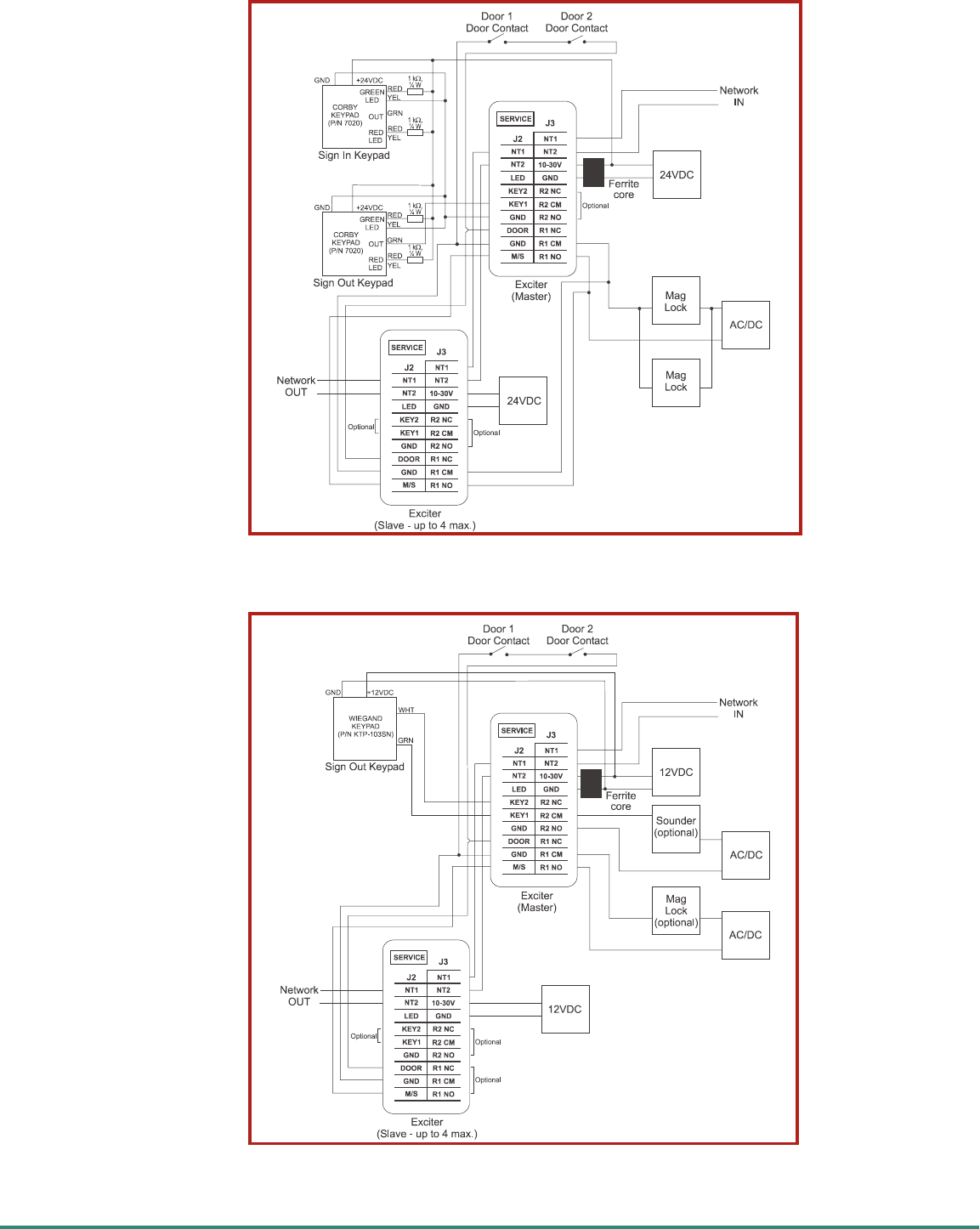
Figure 2: Master Exciter with one slave using its own ID, and two Corby
keypads.
Figure 3: Master Exciter with one slave, and one Wiegand keypad.

Warranty
Xmark’s products are warranted against defects in materials and
workmanship and shall perform in accordance with published
specifi cations for a period of one year. Instantel Inc. reserves the
right to change specifi cations without notice.
Limitation of Liability
This Product has been designed for use to assist in the prevention
of infant abduction.
The range, accuracy, function and performance of this Product may
vary from the published specifi cations due to many factors, including,
without limitation, site impairments from structural effects, metal
objects in the vicinity, placement of the receiver and transmitter,
interference from other electrical devices, atmospheric effects, installa-
tion, and maintenance. There may be other factors, which also affect
performance of this Product.
Instantel does not guarantee that this Product will detect 100% of
infant abductions. Instantel does not guarantee that this Product will
not return false reports of infant abductions.
Monthly testing and maintenance of this Product, as described in the
Product documentation, is essential to verify the system is operating
correctly and to ensure that the probability of detecting an alarm
and/or locating the transmitter are maximized.
The failure to undertake regular testing and maintenance will increase
the risk of system failure and failure to detect infant abductions. The
failure to undertake regular testing and maintenance will increase the
risk of false reports of infant abductions.
Instantel hereby disclaims all warranties, express or implied, arising
out of or in connection with any of its Products of the use or perfor-
mance thereof, including but not limited to, where allowable by law,
all other implied warranties or conditions of merchantable quality
and fi tness for a particular purpose and those arising by statute or
otherwise in law or from a course of dealing or usage of trade.
Instantel’s liability to you or anyone claiming through or on behalf of
you with respect to any claim or loss arising out of the use or misuse of
Instantel’s Product, defective products or materials, improper installa-
tion or maintenance of Instantel’s Product or products or the system
in which they are incorporated, or alleged to have resulted from an
act or omission of Instantel or any person, negligent or otherwise,
shall be limited to:
A) the repair or replacement of defective Product or materials sup-
plied by Instantel during the warranty period as set out in the
Product documentation; or, at the option of Instantel,
B) refund of the purchase price of the Product supplied by Instan-
tel.
In no event shall Instantel be liable for general, specifi c, indirect,
consequential, incidental, exemplary or punitive damages or any
losses or expenses suffered by you or anyone else, whether or not
Instantel, or its employees, offi cers, agents, resellers or installers has
been informed of the risk of such loss or expense and whether or not
such losses or expenses were foreseeable.
Statements
United States—Federal Communication Commission (FCC)
This device complies with Part 15 of the FCC Rules. Operation
is subject to the following two conditions: (1) this device may not
cause harmful interference, and (2) this device must accept any
interference received, including interference that may cause unde-
sired operation.
NOTE: This equipment has been tested and found to comply with
the limits for a Class A digital device, pursuant to Part 15 of the FCC
Rules. These limits are designed to provide reasonable protection
against harmful interference when the equipment is operated in a
commercial environment. This equipment generates, uses, and can
radiate radio frequency energy and, if not installed and used in accor-
dance with the instruction manual, may cause harmful interference to
radio communications. Operation of this equipment in a residential
area is likely to cause harmful interference in which case the user will
be required to correct the interference at his own expense.
Warning: Changes or modifi cations not expressly approved by Xmark
could void the user’s authority to operate the equipment.
Canada—Industry Canada
This device complies with RSS-210 of Industry and Science Canada.
Operation is subject to the following two conditions: (1) this device
may not cause interference, and (2) this device must accept any
interference, including interference that may cause undesired opera-
tion of the device.
thgiLecivreS
ffO.noitarepolamroN
noyratnemoM.desserpniPecivreS
5.0yrevegnihsalF
sdnoces
ehtnierugifnoCotuAnuR.reticxEderugifnocnU
.xobgolaidnoitallatsnIeciveDskroWnoL
nO reticxEehtoterawmrifdaolnwoD.eruliaferawdraH
.xobgolaidnoitallatsnIeciveDskroWnoLehtmorf
thgiLsutatS
deR.rorrEeciveDromralA
evahserusaemytirucesnehwraelcdnasmralarofkcehC
noitarepokcehc,stsisrepnoitidnocfI.detnemelpmineeb
otgnivomerofebemithcaereticxEehtkcehC.reticxEfo
.petstxeneht
fodraobtiucricehtnodetacolniPecivreSehtsserP.1
raeppadluohsmralanA.slanimretehtraen,reticxEeht
ehtneewtebgniriwehtkcehc,tonfI.erawtfosehtni
.CPrellortnoCehtdnareticxE
seciveDskroWnoLehtninottubtseTehtnokcilC.2
snoitacinummocehtskcehcsihT.xobgolaidnoitallatsnI
gninrawafI.rellortnoCehtdnareticxEehtneewteb
.spetsgniwollofehthtiweunitnoc,sraeppaegassem
skroWnoLehtmorfreticxEehtoterawmrifdaolnwoD.3
.xobgolaidnoitallatsnIeciveD
ehtnierugifnoCotuAnuR.reticxEehterugifnoceR.4
.xobgolaidnoitallatsnIeciveDskroWnoL
skroWnoLehtnireticxEehttceleS.reticxEehtteseR.5
.nottubteseRehtkcilcdnaxobgolaidnoitallatsnIeciveD
ehtetadpuotdnammocnorueNdaolnwoDehtesU.6
.erawmrif
tiecalper,reticxEehtxiftonodserudecorpevobaehtfI
.egarevocroftnemecalperehtkcehcdna
neerGdemrA
wolleY noitceteds'reticxEehT(ssergorpnituOngiS/nIngiS•
ssapotgaTawollaotdelbasidyliraropmetsiaera
.)mralanagnisuactuohtiwhguorht
.CPrellortnoCehtybdessapybyltnenamrepreticxE•
adnesodtubsmralaetavitcatonodsreticxEesehT
nihtiwsigatagnitacidniCPrellortnoCehtotegassem
.aeranoitcetedsti
1rofydaetsgnihsalF
owtrofffo,dnoces
yldetaepersdnoces
)rolocyna(
siCPrellortnoCehT.gnitarepoyltnerrucdnammockniW
ehtnoreticxEsihtgniyfitnedifossecorpehtni
.krowtenskroWnoL
Service and Status Lights
The Exciter has a service light and status light, which may be used to
help diagnose problems in its operation. The service light is located
beside the wire terminals, and the status light is located on the
outside of the Exciter.