Xsens Technologies AW-A Wireless base station User Manual Manual
Xsens Technologies B.V. Wireless base station Manual
Manual

© Xsens Technologies B.V.
i
Revisions
Revision
Date
By
Changes
A
14 January 2011
CMO
First version.
B
15 April 2011
CMO
Updated for 3.7 Beta
Updated Wireless configuration menu
Updated Wireless States
Additional Functionality:
Stand-by
Synchronisation with 3rd party devices +
examples
C
15 August 2011
CMO
Added Rotation Matrix export description
Added note about not using maximum update
rate to ensure retransmissions are possible
during recordings.
D
4 November 2011
CMO
Updated for 3.8
Settling time advice added
Added Awinda USB dongle-related information
Added stand-by mode details
Additional 3rd party sync options implemented
Update rate default value
E
14 February 2012
CMO
Updated for 3.8.1
Added Table 1 maximum and typical update
rates and buffering times.
Added information related to magnetic field
disturbances (3.3.1)
F
9 January 2013
MHA
Added Awinda Station and Awinda Dongle to
Declaration of Conformity CE and FCC
© 2010-2013, Xsens Technologies B.V. All rights reserved. Information in this document is
subject to change without notice. Xsens, MVN, MotionGrid, MTi, MTi-G, MTx, MTw, Awinda
and KiC are registered trademarks or trademarks of Xsens Technologies B.V. and/or its
parent, subsidiaries and/or affiliates in The Netherlands, the USA and/or other countries. All
other trademarks are the property of their respective owners.

© Xsens Technologies B.V.
ii
Table of Contents
1 Introduction 1
2 Content Overview 2
2.1 Carrying Case with Contents 2
2.2 Motion Tracker (MTw) 2
2.3 Awinda Station 2
2.4 Awinda USB Dongle 3
2.5 Click-in Body Straps 3
2.6 Software 3
3 Getting Started 4
3.1 Hardware Setup 4
3.2 Software Installation 4
3.3 Tips for Best Practice 4
4 Hardware 8
4.1 Motion Trackers (MTw) 8
4.2 Awinda Station 11
4.3 Awinda USB Dongle 12
4.4 Click-in Body Straps 14
5 Recommended workflow 17
6 MT Manager 19
6.1 Software Installation 19
6.2 Connecting to MT Manager 20
6.3 Connectivity Toolbar 21
6.4 Device List 22
6.5 Wireless Configuration 24
6.6 Preferences 30
6.7 Synchronisation 31
6.8 Orientation Reset 36
6.9 Recording Data 37
6.10 Saved and Exported Data 37

© Xsens Technologies B.V.
iii
6.11 Application Software Development for the MTw 40
7 Xsens Peripheral Software 41
7.1 Magnetic Field Mapper (MFM) 41
7.2 Firmware Updater 41
8 Troubleshooting and Support 43
8.1 Customer Support 45
9 Warranty Liability 46
10 Regulatory Notices 47
10.1 Radio Frequency Exposure and Emission 47
10.2 FCC Statement 48
10.3 CE Declaration of Conformity 49
10.4 FCC Declaration of Conformity 50
11 Appendices 51
11.1 MTw Technical Specifications 51
11.2 Awinda Station Technical Specifications 53
11.3 Awinda USB Dongle Technical Specifications 54
11.4 Xsens Kalman Filter 58
11.5 Strap Down Integration 59
11.6 Coordinate Systems 61
11.7 Orientation Output Modes 65
11.8 Synchronisation Examples 68

© Xsens Technologies B.V.
iv
Abbreviations and Terms
Abbreviation
Description
BAN
Body Area Network
BNC
BNC (Bayonet Neill-Concelman) connector. Common type of RF connector
used for the coaxial cable. Used to connect Awinda Station to third party
devices for synchronisation purposes.
DOF
Degrees Of Freedom
MT
Motion Tracker
MTB
MT Binary Communication Protocol
MTM
MT Manager
PAN
Personal Area Network
SDI
Strap down integration
SDK
Software Development Kit
TTL
Transistor–transistor logic. Used in the synchronisation ports of the
Awinda Station.
XFF
Xsens Firmware File format
XKF-3
Xsens Kalman Filter 3 DOF
XKF-3w
Xsens Kalman Filter 3 DOF for MTw
Term
Description
Quaternion
An orientation representation of complex numbers. A unit length
quaternion is a convenient parameterization of rotations.
Euler Angles
Representation of the spatial orientation of any frame of the space as a
sequence of rotations from a reference frame.
Awinda
Protocol
Patented wireless communication protocol specifically suited for real-time
transmission of mathematically integrated data, such as constructed by a
Strap Down Integration (SDI) algorithm.
Strap Down
Integration
A method to compute an orientation/ position change given an angular
velocity/acceleration of a rigid body. For example computing angle change
using MEMS vibrating gyroscopes.
Delta Angle
Output of strap down integration of the angular velocity data.
Delta Velocity
Output of strap down integration of the acceleration data.
Personal Area
Network
A personal area network (PAN) is that associated with the MTw
development kit. A set of wireless clients communicates with a host
wireless receiver that is remove from the subject wearing the wireless
clients. The wireless receiver is connected directly to the host PC.
Body Area
Network
Differing slightly from a PAN, with the Body Area Network (BAN), a local
wireless receiver is also body-worn, this collects wireless data from all
body-worn devices and transmits wireless data to a remote wireless
receiver, which is connected directly to a host PC.

© Xsens Technologies B.V.
v
Default Folders
Description
Files
Location
Main program
MT Manager
MT SDK
C:\Program Files ... \Xsens\MT Manager
Documentation
MTw User Manual
MTw SDK User Manual
C:\Program Files ...
\Xsens\Documentation
Tutorials / Help files
C:\Program Files ... \Xsens\MT Manager

© Xsens Technologies B.V.
1
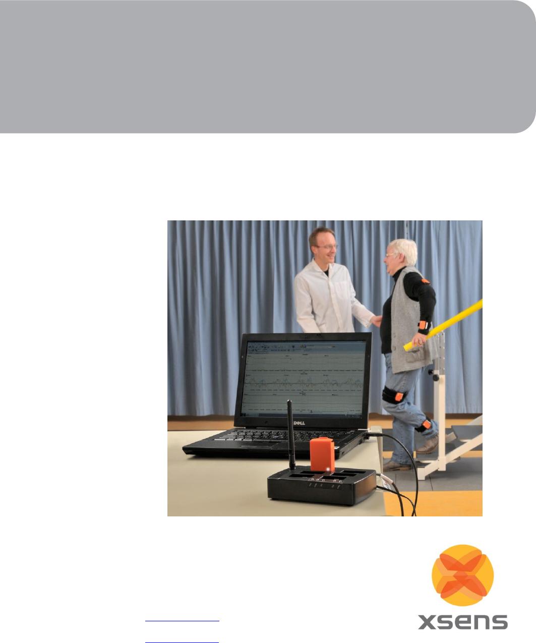
1 Introduction
The MTw™ is a miniature wireless inertial measurement unit incorporating 3D
accelerometers, gyroscopes, magnetometers (3D compass), and a barometer (pressure
sensor). The embedded processor handles sampling, buffering, calibration and strap down
integration of the inertial data as well as the wireless network protocol for data
transmission. Combined with the MT SDK with Xsens Kalman Filter on the host device the
MTw provides real-time 3D orientation for up to 32 wireless motion trackers in a network,
while at the same time also providing calibrated 3D linear acceleration, angular velocity and
(earth) magnetic field and atmospheric pressure data.
One of the unique features of the MTw is the patent-pending Awinda™ radio protocol. The
Awinda protocol is based on the IEEE 802.15.4 PHY. Using this basis ensures that standard
2.4 GHz ISM chipsets can be used. The Awinda protocol ensures time synchronisation of up
to 32 MTw’s across the wireless network to within 10 μs. This is in a range comparable to the
wired systems of Xsens (i.e. the Xbus). Awinda has been specifically developed with inertial
sensor data in mind and will maintain the accuracy of 3D motion tracking even if data is
temporarily lost in radio transmission, while maintaining very efficient use of the limited
available bandwidth. Traditional radio protocols reserve a lot of time for acknowledgement
of data packet reception and re-transmission of data, possibly causing the network
throughput to drop. With Awinda, the data is initially sampled at 1800Hz, is down-sampled
on the processor of the MTw to 600Hz. and using Strap Down Integration (SDI) the data is
transmitted to the Awinda Station. For real-time applications, this means that the accuracy is
preserved even if data packets are lost. For post-processing and analysis, it means that there
is no missing data. Buffered data at the MTw is made available to the host in a configurable
re-transmission scheme that will flush the buffered data to the host when excess bandwidth
is available.
The completely wireless nature of the MTw widens the possible areas of applications,
improves the speed of donning the motion tracking systems onto test subjects, or patients.
Because inertial sensor technology does not rely on line of sight and is not influenced by
lighting conditions, the systems can be worn in the field, with no need for simulated
environments.
Fields of use:
Biomechanics
Rehabilitation
Sports and exercise science
Ergonomics
Virtual reality
Animation
Motion capture
© Xsens Technologies B.V.
2
2 Content Overview
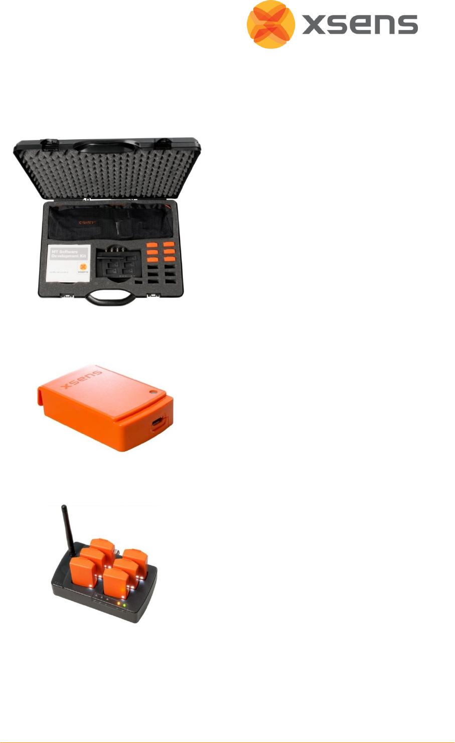
2.1 Carrying Case with Contents
The MTw Development kit arrives in a case,
approximately the size of a common
briefcase.
A standard MTw Development kit contains:
6 MTw's
1 Awinda Station
1 USB cable
1 power cable
Awinda USB Dongle
1 set of full body Click-in body straps
CD with MT Manager and MT SDK
User manual
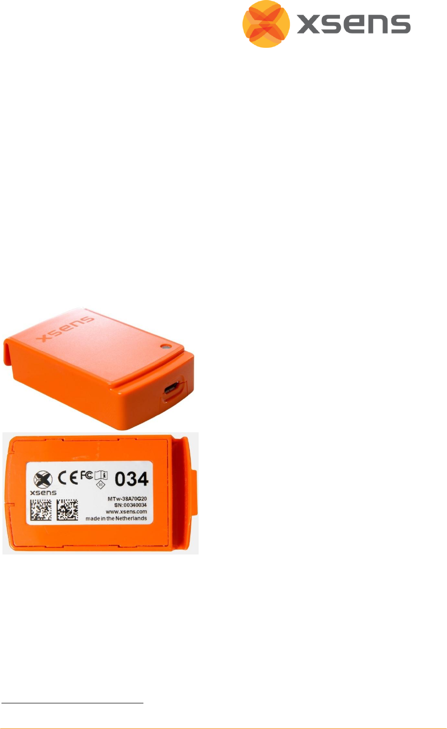
2.2 Motion Tracker (MTw)
MTw’s are miniature inertial measurement
units containing 3D linear accelerometers,
3D rate gyroscopes, 3D magnetometers and
a barometer. The casing has been designed
with a click mechanism, to ease positioning
on the body using click-in body straps. For
more details see Section 4.1.
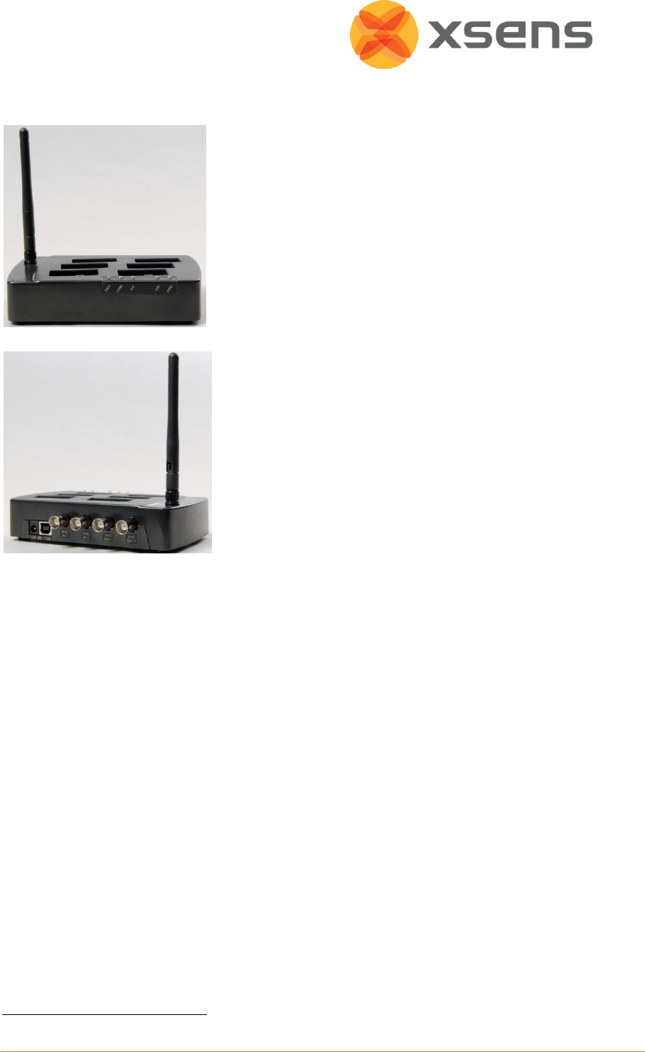
2.3 Awinda Station
The Awinda Station. It controls the reception
of synchronised wireless data from all
wirelessly connected MTw’s and charges up
to 6 MTw’s simultaneously.
It can receive wireless data from up to 32
MTw’s. For more details see Section 4.2.
© Xsens Technologies B.V.
3
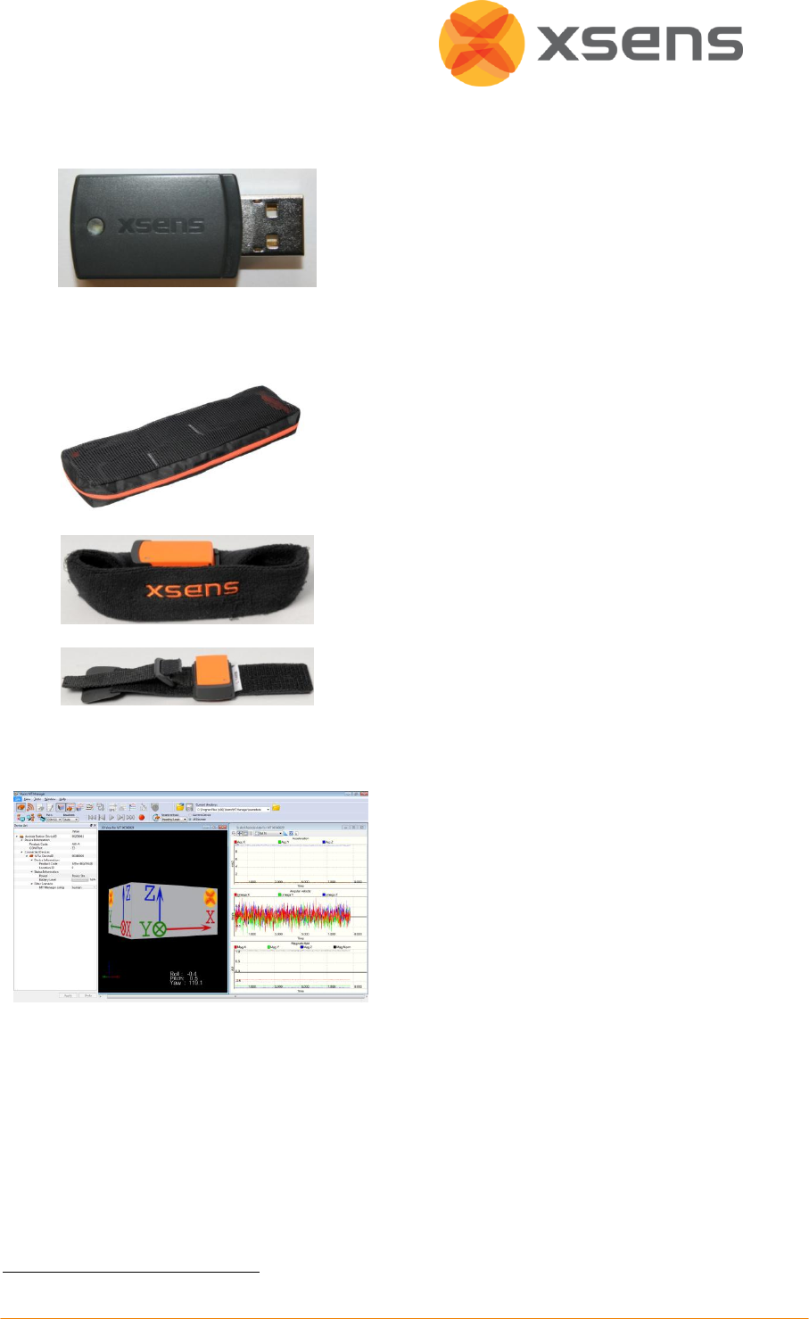
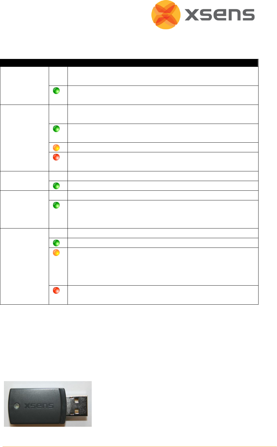
2.4 Awinda USB Dongle
The Awinda USB Dongle has the same
wireless capabilities as the Awinda Station.
It controls the reception of synchronised
wireless data from all wirelessly connected
MTw’s. It can receive data from up to 32
MTw’s. For more details see Section 4.3.
2.5 Click-in Body Straps
The MTw Click-in body straps are a one-size
fits all mounting system. They have specially
designed click mechanism enabling the
MTw to be quickly and easily clicked into
place and removed again for charging.
When clicked in, they maintain a robust
connection to the strap. The straps are
made from strong elastic material, backed
with silicone rubber to ensure comfortable
and close fixation to the skin. They are
fastened using Velcro. For more details see
Section 4.4.
2.6 Software
The MTw development kit is supplied with
a visualising and recording software
package, MT Manager. This facilitates quick
and easy use of the MTw and Awinda
Station.
In addition, a MT Software Development
Kit (SDK) is provided, with example code in
C, C++, LabView, MATLAB and Linux.1 The
MT SDK is intended to make software
application development for the MTw
easily accessible. For more details see
Section 6.11.
1
. Future releases will include example code in Excel.

© Xsens Technologies B.V.
4
3 Getting Started
3.1 Hardware Setup
Dock the MTw’s into the Awinda Station. Connect the Awinda Station to the PC, using the
USB cable provided. The mains power supply is only needed for charging the MTw, turning it
on from the Transport (or switched off) mode and while carrying out firmware updates, but
we recommend connecting the power supply immediately to charge the MTw’s. For wireless
communication between MTw’s, the Awinda Station and the PC, it is not necessary to plug
the Awinda Station to the mains power supply since the wireless interface in the Awinda
Station is powered by USB from the PC.
See Section 4.1 for details about the MTw.
See Section 4.2 for details about the Awinda Station.
See Section 4.3 for details about the Awinda USB dongle.
See Section 4.4 for details about the MTw Click-in body straps.
3.2 Software Installation
Insert the CD supplied to run the MT Manager Installer (setup.exe). If using Windows
XP/Vista/7 operating systems, install with 'Administrator' or 'Power User' rights. Follow the
on-screen instructions.
See Section 6.1 for detailed MT Manager installation instructions.
3.3 Tips for Best Practice
3.3.1 Magnetic Distortion
For best results when measuring with the Xsens MTw, it is advised to avoid highly
magnetised areas when carrying out measurements; in particular in the beginning. XKF-3w
uses the local magnetic field to compute heading. When this signal is distorted due to close
proximity of a strong magnet, or ferromagnetic material (iron or steel), accuracy of results
may decrease.
Check the magnetic norm of the environment. To check the magnetic norm, the system
should be installed and running, with at least one MTw active. Open the inertial data graph
and look at the Magnetic Norm curve (black line) while moving in the measurement area.
Areas for which the magnetic norm variation remains within ±0.2 are best for carrying out
measurements.
3.3.1.1 Types of Magnetic Disturbance
Figure 1 below gives an indication of how ferromagnetic objects lying in a homogenous
magnetic field cause magnetic field distortions. It is clear from this figure that only when
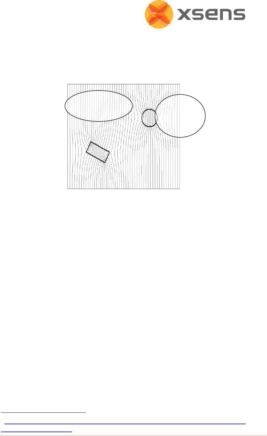
© Xsens Technologies B.V.
5
close to the (ferro-) magnetic material can the material be considered as disturbing, since
the field lines bend towards the object when in close proximity. For more detailed
information about the influence of magnetic field on orientation, see the PhD thesis “Inertial
and magnetic sensing of human motion” D. Roetenberg 2006
1
.
Figure 1: Simulation of ferromagnetic objects in free space with a homogeneous magnetic
field
Homogenous magnetic field
As mentioned above, it is advised to avoid, at least starting a measurement in a highly
disturbed magnetic environment (in a magnetic norm of about 2 or 3). If however, the
measurement begins with a magnetic norm of around 2 or 3, and remains within ±0.2 of this
value, the orientation should remain accurate.
If the homogenous and highly disturbed magnetic field is due to the MTw fixed to an
instrument, or a prosthesis, it is best to carry out magnetic field mapping for this MTw (see
section 7.1). This instructs XKF-3w algorithm that the magnetic field has a new value.
Varying magnetic field
The XKF-3w algorithm can compensate for areas of fast fluctuating magnetic fields.
However, slow, large (>±0.2) changes are more difficult for the algorithm to compensate for,
over periods of time longer than approximately 30s, since the algorithm will constantly be
updating its new heading value.
NOTE:
Do not expose the MTw to very strong magnetic fields. There is a chance the MTw may
become magnetized which will render the calibration values of the magnetic field sensors
1
.http://www.xsens.com/images/stories/PDF/Inertial%20and%20Magnetic%20Sensing%20of
%20Human%20Motion.pdf
Homogenous
magnetic field
Disturbed
magnetic
field

© Xsens Technologies B.V.
6
inside the MTw inaccurate. Performing a Magnetic Field Mapping on the MTw may recover
the calibration if the magnetization is not too strong.
3.3.2 Settling Time
As with all filters of its kind, the XKF-3w filter is based on history. For this reason, some time
is needed for the XKF-3w filters to settle to a stable state, this is referred to as “settling
time”. Users should be aware that prior to a measurement, the MTw’s should be allowed to
reach some filter stability. In practice this means, that users should try to minimise
movement when making a wireless connection. Furthermore, depending on the update rate,
users should minimise movement, or keep any movements to calm and slow movements for
the first few seconds, to one minute after entering measurement mode.
3.3.3 Operating Conditions
The MTw has been designed to be used or worn close to the human body. Take care when
exposing the MTw to strongly deviating environmental conditions. The recommended
operating temperature is between -20°C and +55°C ambient temperature. If operated
outside this temperature range performance may decrease or the device may become
damaged. Fast transient temperature fluctuations may cause significant temperature
gradients across the device. Such gradients cannot be properly modelled by temperature
compensation and may therefore decrease performance. Additionally, operating around 0o
may cause water particles to freeze and condense around the components, causing potential
damage to the internal electronics. For optimal performance, the ambient temperature
should remain as constant as possible during the measurement. Cold environments may
provide shorter operation time of the trackers.
The MTw and Awinda Station must be kept dry at all times. Condensation and water may
damage the internal electronics. Using the MTw with the straps will protect the MTw to
body moisture to a limited degree.
Protect the MTw from violent handling such as drops on hard surfaces. Excessive shocks or
violent handling may damage the MTw or render the factory calibration no longer
applicable. When handling the MTw at a desk, it is advised to place cushioning material
between the desk and the MTw.
Do not put MTw’s in the pockets in the suit case while in operation. Due to the high thermal
insulation of the foam then surrounding the MTw the device will not be able to dissipate the
small amount of heat that it generates during operation and it may become (too) hot.
3.3.4 Absolute Maximum Ratings
Stresses above the absolute maximum ratings to the MTw may cause permanent damage to
the device components.

© Xsens Technologies B.V.
7
3.3.4.1 Absolute Maximum Rating MTw
Shock (any axis)
TBD
Input Voltage
-0.3 V … 6 V (note power is supplied only via USB)
Temperature During operation
-10 oC - +60 oC
Temperature During charging
0 oC - +45 oC
3.3.4.2 Absolute Maximum Rating AWINDA Station
DC Input Voltage
-0.3 V … 16 V (Use included DC adapter)
SYNC (BNC) inputs
-0.5 to 3.8V
Operating Temperature
-20 oC - +80 oC
Exposure to absolute maximum rating conditions for extended periods may affect device
reliability.
NOTE: Drops onto hard surfaces can cause shocks of greater than 20000 m/s2 (2000 g)
exceeding the absolute maximum rating of the device. Care should be taken when handling
to avoid damage. Drops causing shock greater than absolute maximum ratings may not
destroy the device but will permanently alter the properties of the physical motion sensors,
which may cause the device to become inaccurate. If this occurs, please contact
support@xsens.com to investigate if the MT should be returned for a check.
3.3.5 Keeping the Hardware Clean
The housing of the MTw and Awinda Station are waterproof. However, the housing is not
watertight. To keep the Awinda Station and the MTw’s clean, use a damp cloth to wipe the
surfaces.
© Xsens Technologies B.V.
8
4 Hardware
The MTw Development Kit is comprised of both software and hardware. This section deals
with all hardware aspects. The hardware of the MTw development kit includes the motion
trackers, the Awinda Station and the click-in body straps.
4.1 Motion Trackers (MTw)
The MTw provides 3D angular velocity using rate gyroscopes, 3D acceleration using
accelerometers, 3D earth magnetic field using magnetometers, as well as atmospheric
pressure using the barometer. Combined with Xsens algorithms, 3D drift-free orientation is
provided. The MTw is an excellent measurement unit for orientation measurement of
human body segments, in particular because it is also designed to maintain very high
accuracy time synchronization of the individual sensor readout across a wireless network of
multiple units. This is essential when measuring joint angles accurately.
Front side of the MTw where the micro
USB is connected. On the top is LED giving
indications of device status.
Back side of the MTw, displaying various
regulatory notices and 2D barcodes used
by Xsens for quality control and tracking, as
well as the MTw product code (MTw-
38A70G20) and serial number1 (SN). Note
that the last three digits of the SN are
displayed in a large font, for the user to
easily identify individual MTw’s. This aids
the user for example when placing MTw’s
on particular body segments.
The MTw is powered using a LiPo battery. The battery can be in operation for up to 3.5
hours, in stand-by for approximately 90 hours and is fully recharged after one hour docked in
the Awinda Station (with a power supply connected to the Awinda Station). For more
technical details on the MTw, sensor component specifications and orientation
performance, see Section 11.1.
1
Also known as Device ID.

© Xsens Technologies B.V.
9
4.1.1 MTw LED Indications
The following lists the LED indications of the MTw, which are a combination of the device
states and the Awinda protocol states of the MTw:
State
Description
Power-up
Blinking.
Docked and
fully
charged
ON
Charging
Slow fade from ON to OFF as a percentage [%] of battery status.
A slow cycle means an almost full battery. A quick cycle means an almost
empty battery.
Scanning
Pulsating.
Connected
Slow symmetric ON/OFF toggle in sync with Awinda Station (CONN LED).
Measuring
Fast symmetric ON/OFF toggle in sync with Awinda Station (CONN LED).
Battery Low
Quick Triple Pulses, overrides other states until charging again.
Flushing
Double pulse in sync with Awinda Station (CONN LED).
Stand-by
OFF. Blinks for 3 s, if a change in magnetic field has been detected, while
searching for a radio connection.
4.1.2 MTw Stand-by Mode
Following a wireless connection, the MTw is in operational or measurement mode. When
the radio of the Awinda Master has been switched off, for longer than 30 seconds the MTw
will enter stand-by mode. In this mode, the MTw will shut down its power, but monitor
change in magnetic field every second. See below for exiting standby mode.
4.1.3 Exiting stand-by mode
With MT SDK 3.8 instead of searching only for a wireless link, the MTw will monitor its
magnetic field once every second. If the magnetic field has changed considerably, and there
is a wireless link to an Awinda Master available, the MTw will automatically become active
again.
To bring the MTw back from stand-by to operational mode, reactivate the radio of the
Awinda Master, and move the MTw; a simple 90 degree turn, or simply lifting it from the suit
case to apply to the subject should be enough. As an alternative, this can also be done by
changing the magnetic field around the MTw. Consider moving a pair of stainless steel
scissors (NOT A MAGNET) over the MTw, to change the field and reactivate it.

© Xsens Technologies B.V.
10
4.1.4 Estimated battery life with stand-by mode activated
Bat. Capacity at sleep start
[%]
Estimated time to full
discharge in standby [hrs]
Measuring time left after 8
hrs in standby [hrs:min]
100
88
2.18
75
64
1:45
50
44
1:06
25
20
0:24
10
8
0:00
© Xsens Technologies B.V.
11
4.2 Awinda Station
Front view of the Awinda Station, showing the LEDs. A
description of the LEDs are described in Section 4.2.2
below. On top are docking spaces for 6 MTw’s with
regressed micro USB connectors. On the side is a
foldable and rotatable 2.4 GHz antenna for maximum
range.
Back view of the Awinda Station, showing the DC
power connector, the USB connector and 4 BNC sync
I/O connectors for synchronisation with external
devices 1. See 11.2 for more technical specifications of
the Awinda Station.
4.2.1 Awinda Station Synchronisation Ports
On the back of the Awinda Station there are four BNC ports, two Sync In ports and two Sync
Out. The ports have been configured to send (Sync Out) or receive (Sync In) TTL pulses 0-
3.3V. For software configuration of the synchronisation channels, see Section 6.7.
1
© Xsens Technologies B.V.
12
4.2.2 Awinda Station Status LED
The Awinda Station has five LED indicators. From right to left, these indicators are:
LABEL
LED
DESCRIPTION
CHRG
[CHaRGer
functionality]
OFF
When no mains power supply is connected to the Awinda Station.
GREEN: When 12V power supply is connected (mains power
supply).
STAT
[STATus of the
Awinda
Station]
OFF
OFF: When no USB connection is present and when MT Manager is
not started.
GREEN: Both USB connection present and MT Manager running
connected to driver.
ORANGE: USB connection to host PC is present.
RED: Only power supply connected or error has occurred, e.g., a
short-circuit of an MTw.
EXT
OFF
Remains off unless external connection made.
GREEN: External connection e.g. sync port.
CONN
OFF
OFF: No wireless connection.
GREEN slow blinking: (1 blink per second), radio switched on. When
MTw connects, MTw LED and CONN LED blink synchronously.
Fast blink: Measurement Mode.
DATA
OFF
OFF: No data received.
GREEN: Measurement mode.
ORANGE: Flushing. Flushing is the action of transferring data that
has been stored on the MTw buffer, while the MTw was out of
range and unable to transfer data in real-time to the Awinda
Station.
RED: Recording mode is active. This allows the remote monitoring
that the host PC has initiated a recording successfully.
Note: The power supply is needed to charge the MTw’s or to change from power off to
power on. Only the power supply is needed for charging purposes (USB is not needed in this
case). Power supply and USB connection are required for firmware updates.
Power supply is not needed for wireless communication (e.g. measurement/recording).
4.3 Awinda USB Dongle
See 11.3 for more technical specifications of the
Awinda USB Dongle.

© Xsens Technologies B.V.
13
4.3.1 Awinda USB Dongle LED
The Awinda USB dongle has one white LED.
State
Description
Radio Off
LED off.
Scanning for
MTw’s
Pulsating LED.
Connected
Slow symmetric ON/OFF toggle (MTw blinks in sync with LED of
dongle).
Measuring
Fast symmetric ON/OFF toggle (MTw blinks in sync with LED of
dongle).
© Xsens Technologies B.V.
14
4.4 Click-in Body Straps
The MTw Click-in body straps have been designed to ensure that the user can enjoy as much
flexibility as possible. The user may first insert the MTw into the strap, then fasten the strap
to the body (recommended). Alternatively, prepare the subject by first attaching the straps,
to the body locations, then insert the MTw’s at the appropriate locations.
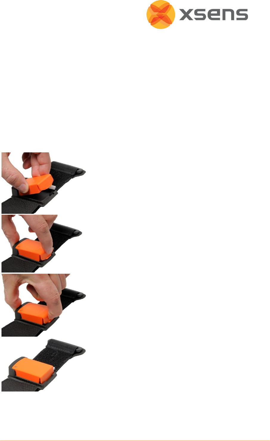
4.4.1 Putting MTw’s into Strap Holders
Each system is supplied with a series of stickers, with the ID of the MTw printed. The user
can use this to fix to the MTw holder on the straps, to enable the user to remember more
easily where each MTw is fixed on the body. The user can also set a numerical Location ID in
MT Manager Device List (Section 6.4.2) to code Location ID to, e.g., body segments.
To put the MTw into the holder of the straps, slip the
MTw, gently into the “cup” of the holder.
Press the clip of the MTw against the MTw housing.
Press the MTw vertically into the housing.
Release the clip into the clasp of the holder. Take care to
ensure that the MTw is completely and firmly
restrained.
4.4.2 Putting on the Straps
It is possible for the user to put the straps onto their own body segments, however, to
ensure tight and stable fit, it is advisable to have someone else fasten them.
Before each use, pre-stretch the straps to remove any initial stiffness.

© Xsens Technologies B.V.
15
Insert each MTw, into the correct strap holder. Note the location of the MTw ID with
respect to the body location, for future use.
For consistency, it is recommended to display the Xsens text in the correct orientation
for reading – this means that the cup should be the lowest point.
Attach the straps to the appropriate body segments.
1
Check that the straps are fastened tightly enough to the body.
To do this, the subject wearing the straps should walk or run for a few seconds, or
perform sample movements that will be made during the measurements. If the
straps become loose, re-tighten them and repeat the check.
NOTE: When tightening the straps, pull the strap at the point where it runs through the
plastic buckle, not just at the end!
4.4.3 Recommended Locations
While inertial sensor technology facilitates freedom of movement and minimises restrictions
imposed by camera and lighting, users should remain as vigilant when placing inertial
sensors to the body as when placing any other human measurement system to the body.
Users should be aware of skin motion artefact, which can occur with all forms of human
(movement) measurement systems. When placing Xsens MTw to the body, using the Click-in
body straps helps to ensure that the MTw is fastened tightly and robustly to the skin. The
following points should be taken into consideration:
Be aware of muscle contractions that may cause unwanted movement of the MTw
Place MTw’s on areas with least likelihood of moving due to a muscle contraction.
For measurements of the extremities, for example forearm, take into account the
measurement desired. At Xsens, we place the MT closer to the wrist, as this provides
more information about 3D movement. Furthermore, the wrist area has less fatty tissue,
decreasing the chances of skin motion artefact. (See 4.4.4 for instructions for fastening
the forearm strap.)
For the upper arm, the location is less critical, as the upper arm has more musculature.
On the lower leg, two locations have been described in literature as good placement.
1. On the tibia, close to the knee
2
.
2. On the lateral side of the lower leg, aligned with the fibula, 6cm above the lateral
malleolus
3
.
For upper leg measurements, we recommend placing the MTw close to the knee, on the
lateral thigh, as this has less probability of having fatty tissue, compared e.g. to closer to
1
Configuration sheets with recommended MTw positions for full body measurement are
available upon request.
2
Cloete, T.; Scheffer, C.”Repeatability of an off-the-shelf, full body inertial motion capture
system during clinical gait analysis” Engineering in Medicine and Biology Society (EMBC),
2010 Annual International Conference of the IEEE 11 Nov 2010 pp 5125 - 5128
3
Cutti AG, Ferrari A, Garofalo P, et al. ‘Outwalk’: a protocol for clinical gait analysis based on
inertial & magnetic sensors. MED BIO ENG COMPUT, 2010; 48(1):17-25.

© Xsens Technologies B.V.
16
the hips. The silicone backed strap, combined with the pelvis belt, this helps to ensure
that this strap does not slide along the leg, during movement e.g. gait measurements.
For pelvis motion measurement, place the MTw at the small of the back. Tightening the
pelvis belt of the pelvis, we recommend using the MTw pelvis
4.4.4 Forearm Strap
The forearm straps have been designed slightly differently from the others, with an
additional Velcro strap to ensure a tight fit. To fasten the forearm strap to the subject:
Ensure that the
rubber touches the
skin, to optimise
subject comfort.
Fasten the inner
(broad) Velcro strap.
Insert the smaller
Velcro strap into
buckle.
Wrap around,
ensuring a tight fit.
© Xsens Technologies B.V.
17
5 Recommended workflow
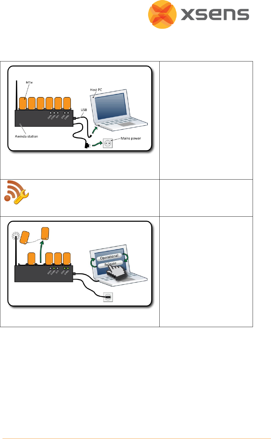
To start up, the Awinda Master
must be plugged into the USB
port of the PC.
The ID of the Master and
docked MTw’s is displayed in
the device list. See 0.
Go to wireless configuration.
Select a radio channel and
switch the radio on (enable).
See 6.5.
When an MTw is undocked, its
radio looks for a station to
connect to.
The wirelessly connected MTw’s
appear in the list.
When all required MTw's are
connected, set the update rate
and either make operational or
enter measurement mode
directly.
See 6.5.6 for selecting the best
update rate.
© Xsens Technologies B.V.
18
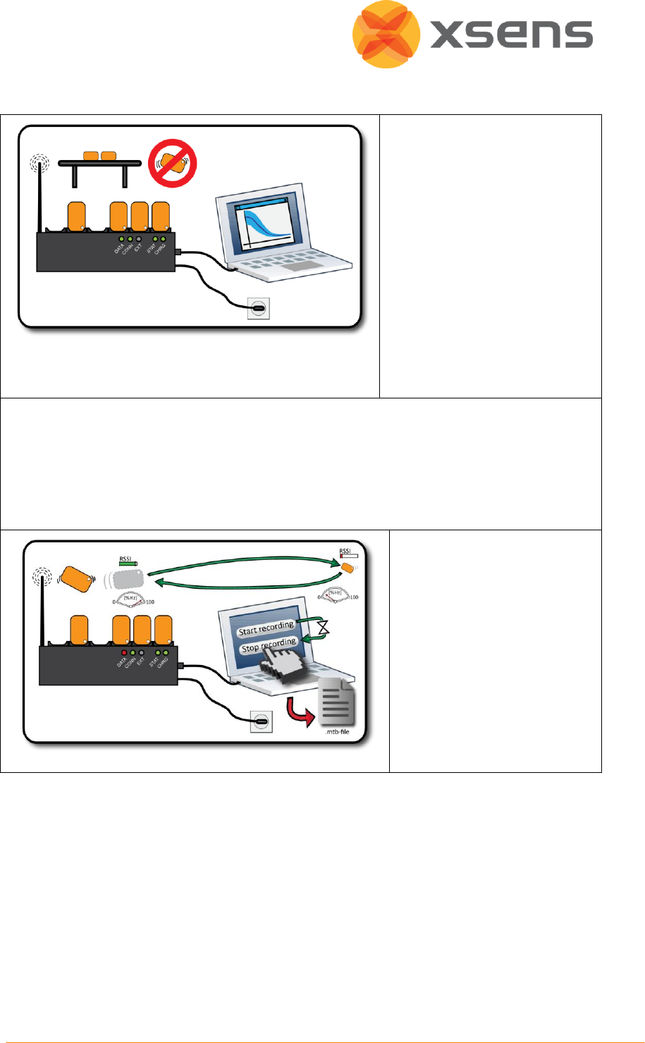
From operational mode,
measurement mode can be
initiated.
When “Start Measuring” is
clicked, make sure that the
MTw is kept still.
For best results, data should be
measured and recorded in the
same environment as when
measurement mode was
initiated.
Like all filters of its kind, the XKF‐3w filter is based on history. Therefore time is needed for
the XKF‐3w filters to settle to a stable state. This time is called settling time, see 3.3.2.
For about one minute after entering measurement mode, make calm, slow movements to
warm up the filters (the actual time depends on the amount of trackers in use, but one
minute should be sufficient).
To check if the filters have
been stabilised, ensure that
the orientation of the MTw
doesn’t change, when the
MTw is stationary (in a
magnetically undisturbed
environment).
When in measurement mode,
recording can be made.

© Xsens Technologies B.V.
19
6 MT Manager
Each MTw Development Kit is accompanied with MT Manager, an easy-to-use software
interface facilitating visualisation, recording and exportation of inertial sensor data.
Additionally, the MTw Software Development Kit (SDK) is provided, giving full access to all
data and configurations of the MTw, with accompanying documentation and example code
to enable software developers to create customised (real-time) visualisation and recording
application software. For more details about the SDK, please see Section 6.11.
The MT Manager software has been designed for Windows 7. It is easy-to-use software with
familiar Windows user interface, which allows the user to:
View and modify device settings and properties
Configure the Awinda wireless interface
Configure synchronisation with third party devices
Real-time visualisation of:
3D Orientation
3D Inertial and magnetic data
Barometric pressure sensor data
Status data
Record native binary log files of data from motion trackers (.MTB files)
Log file export to ASCII
The MT Manager is therefore an easy way of getting to know and to demonstrate the
capabilities of the Motion Tracker.
6.1 Software Installation
If users have previously installed Xsens MT SDK
1
, first uninstall the previous version of MT
SDK, as well as the USB drivers from add or remove programs in the control panel. The USB
drivers are listed as 'Windows Driver Package - Xsens USB-serial Converter Driver Package' in
Add/Remove Programs. Uninstall all entries of these drivers from the list.
NOTE: Do not connect the Awinda Station to the PC before fully installing the MT SDK.
Insert CD provided to install MT SDK on a computer running Windows using the MT SDK
Setup application on the CD provided. The installation will start automatically
2
if “Autorun” is
enabled on the CD player, otherwise, run the setup.exe file in the location of the CD ROM.
Windows Vista/7 users, should choose “Open folder to view files” in the Autoplay dialog.
1
Do not uninstall the MT SDK 3.3 if you need to continue to work with your MTi, MTx, MTi-G
or Xbus Master since 3.8only officially supports the MTw.
2
If the installation application does not start automatically, double-click “setup.exe” in the
root folder of your CD/DVD drive, e.g. E:\
© Xsens Technologies B.V.
20
Right-click “Run setup.exe” and “run as administrator”. Follow the on-screen instructions.
When prompted, enter the serial number for the product. This number can be found on the
letter accompanying the MT SDK CD-ROM. User the default installation folder or select
preferred installation folder, and click next.
6.2 Connecting to MT Manager
To initialize the Awinda Station and MTw’s, dock the MTw’s in the Awinda Station. Physically
connect the Awinda Station, to the PC using the USB cable provided.
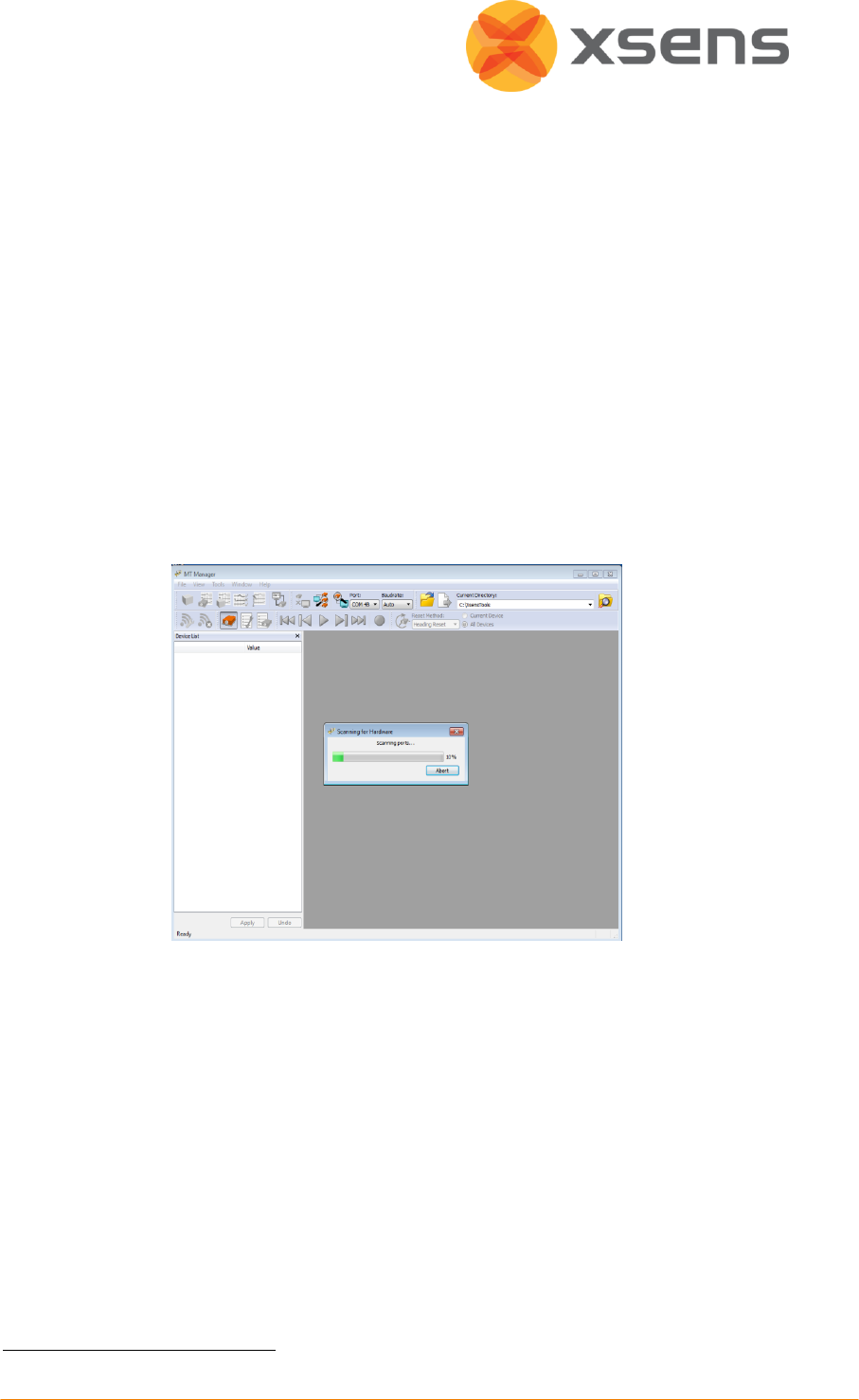
6.2.1 Automatic COM Port Scanning
Upon execution of the MT Manager, all available COM ports on the host PC are
automatically scanned for Xsens hardware. Progress is displayed during scanning in the
status bar on the bottom right corner of the main window. If the PC has a large number of
COM-ports (e.g. if Bluetooth drivers are installed) this may take some time.
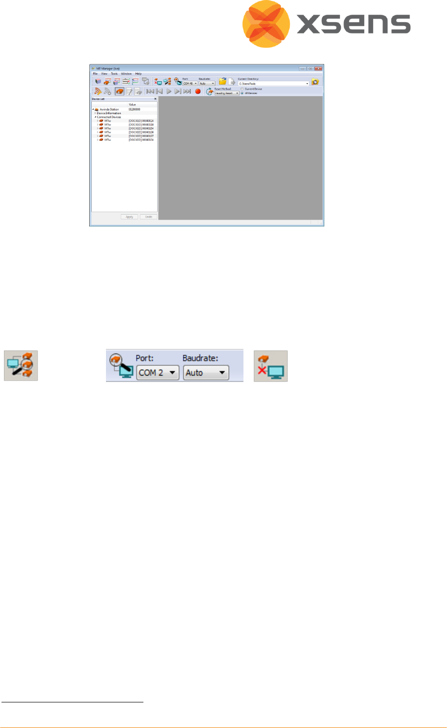
Upon successful connection
1
, the “Device List” sub-window appears with a list of connected
devices and respective Device ID number (when necessary press the Device List icon).
The Wireless Configuration section (6.4.2) describes how to connect the MTw’s as sub-
systems (clients) of Awinda.
NOTE: If synchronisation configuration is needed first enable these settings (See section 6.7)
before carrying out the wireless configuration.
1
Please refer to Section 8 in case of problems.
© Xsens Technologies B.V.
21
If the automatic scanning at start up does not reveal any connected devices, ensure that
there is a USB connection and manually scan for ports using the functions in the connectivity
toolbar.
6.3 Connectivity Toolbar
The following items are available on the connectivity toolbar, for manual COM port
scanning/disconnecting.
Scan all ports
Scan single port
Disconnect COM port1
6.3.1 Scan All Ports
All available COM ports are scanned for connected devices.
6.3.2 Scan Single Port
Choose an active COM port from the appropriate drop down menus to link this port to MT
Manager, click “Scan single port”.
6.3.3 Disconnect COM Port
To disconnect all hardware connected, select the “Disconnect” button.
1
This can also be used to close an open file.
© Xsens Technologies B.V.
22
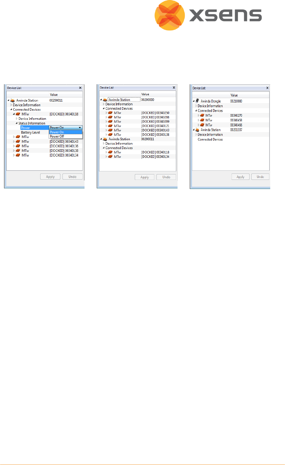
6.4 Device List
The Device List contains all of the information about the devices connected to MT Manager.
It is possible to connect more than one Awinda Station (and associated MTw’s) at one time
to MT Manager.
Single Station: Power On
Power Off
Two Awinda Stations
Connected
Wireless connection with
Awinda USB Dongle
6.4.1 Power On/Off
When docked it is possible to power off the MTw’s, to a fully powered down “Transport
Mode”. To do this, select Power Off from the drop down, menu and click “Apply”. It is
important to “Apply” changes or they are lost after e.g. a rescan or if removed from the
Station.
To re-enable the power, simply dock the MTw back into the Awinda Station; it will wake up
by the power connection.
It is best to power off unwanted MTw’s before continuing with the wireless configuration. If
the user decides to power off the MTw after wireless configuration, it will be necessary to
re-dock the MTw, Power Off and then reconfigure the wireless network.
© Xsens Technologies B.V.
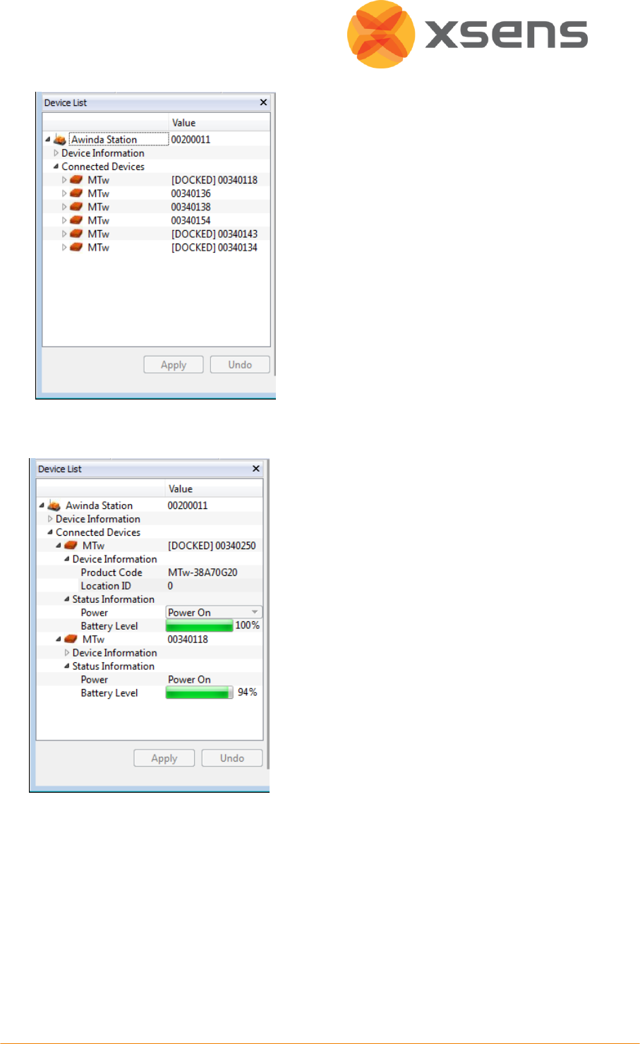
23
When the wireless configuration has
been performed, the Device List is
updated such that all connected MTw’s
are listed, with the indication of whether
they are still in the Awinda Station
(docked) or wirelessly connected.
MTw’s docked or wirelessly connected is
shown as a Connected Device in the
Device List. Still docked (and not
previously configured wirelessly) have the
index “[DOCKED]”.
6.4.2 Location ID
Users can change the numerical Location ID
of docked MTw’s in the Device List. This is
useful for example if users want to use a
numerical code for a given body segment.
After making changes in the Device List,
click Apply to make sure changes are
implemented.
© Xsens Technologies B.V.
24
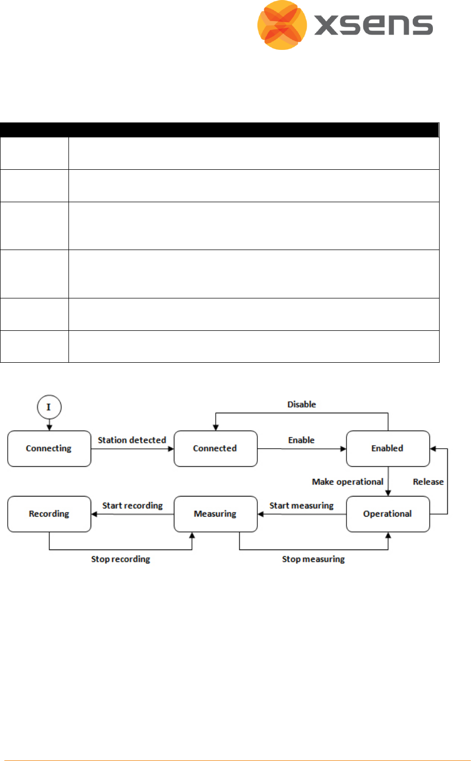
6.5 Wireless Configuration
When the Awinda Station is connected to the MT Manager, the Awinda system can be in one
of the following states:
State
Description
Connecting
The Station is plugged into the USB connection and MT Manager tries to
establish the link to the Station.
Connected
The Station is plugged in to the USB and detected by MT Manager. The radio
is not transmitting.
Enabled
The station is broadcasting (i.e. radio enabled) on the specified channel and
MTw’s can detect this transmission and connect. MTw’s that connect but
should not be part of the configuration can be rejected.
Operational
All the necessary MTw’s are connected and no more new MTw’s can connect.
The system is ready to start the measurements using the indicated maximum
frame rate or the user can specify a lower one.
Measuring
The MTw’s are measuring and transmitting data to the station. The station
relays the measurements to MT Manager.
Recording
Any missed data packets are retransmitted in this state, provided that the
maximum update rate is not selected.
The state transition diagram is illustrated below:
© Xsens Technologies B.V.
25
State
Transition
Description
Next State
Connecting
Station
detected
MT Manager and Station are connected.
Connected
Connected
Enable
User indicated that the system can be
enabled.
Enabled
Enabled
Make
operational
User indicated that system can become
operational.
Operational
Disable
User indicated that the system is to be
disabled.
Connected
Operational
Start
measuring
User indicated that the system can start
measuring.
Measuring
Release
User indicates that system is no longer
operational, but still enabled.
Enabled
Measuring
Stop
measuring
User indicates that measuring can be stopped.
Operational
Start recording
User indicates that the recording is to be
started.
Recording
Recording
Stop recording
User indicates that the recording can be
stopped.
Measuring
It is possible to enable and disable the radio link using the wireless configuration window.
Likewise, rejecting and accepting motion trackers for a given Awinda Station.
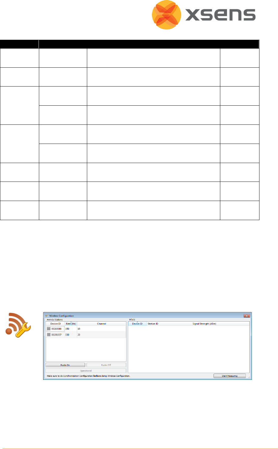
6.5.1 Setting Up a Wireless Network in MT Manager
NOTE: If synchronisation with third party devices is needed first enable these settings (See
section 6.7) before carrying out the wireless configuration.
To configure the wireless network to be used, including selection of MTw’s, and the update
rates, go to > Tools > Wireless Configuration, or use the shortcut button:
As shown above, the wireless configuration menu is split into two sections:
1. On the left hand side are details about the detected Awinda Master(s). Here also the
Update Rate and the Radio Channel, per Awinda Master can be configured.
2. On the right hand side are details about the MTw and the associated radio signal
strength.
© Xsens Technologies B.V.
26
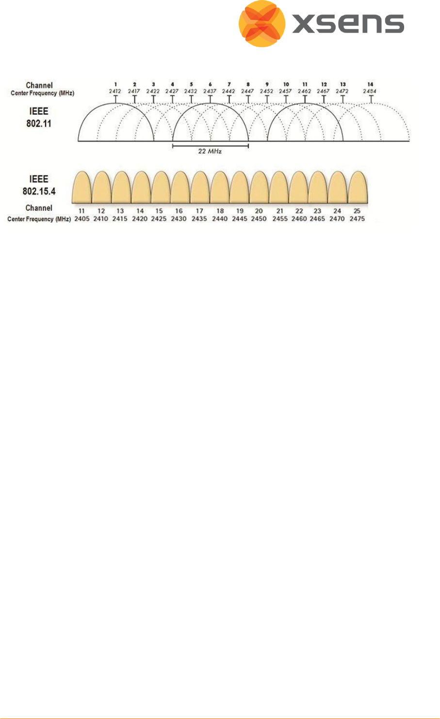
6.5.2 Choosing a Radio Channel
Figure 2: Overview of channels operating around 2.4GHz; for ease of channel selection
Figure 2 provides an overview of the allowed channels for operating on IEEE 802.15.4, the
standard that Awinda is based on, around 2.4 GHz. The bottom row of the figure shows the
channels on the 2.4GHz, the top row shows how WiFi channels use the spectrum. This
should indicate to the user that the best channels to use when you know which channel WiFi
is on. When in an environment where WiFi is also expected to be in prevalent use, but you
are not sure which channels, try Channels 11, 15, 20 or 25.
Bluetooth uses all of the spectrum around 2.4 GHz, but will (try to) avoid channels in use by
other systems including Awinda channels.
6.5.3 Select Radio Channel for Wireless Connection
A number of wireless frequency channels are available to connect the Awinda Master with
the MTw’s. When the wireless configuration menu is open, create the wireless network by
first selecting the radio channel for communication between the Awinda Master and the
MTw’s.
To select the radio channel, double click on the value under the heading “Channel” and
select the radio channel from the drop down menu. This channel will be enabled on the
Awinda Master.
6.5.4 Turn Radio On
After selecting the radio channel for the wireless communication, click “Radio On”. The radio
transceiver of the Awinda Master will turn on and it which will search for MTw’s on this
channel.
For a wireless connection between the Awinda Master (either the Awinda Station or the
Awinda USB Dongle) and the MTw’s, the MTw’s should not be docked in the Awinda Station,
because while docked, the radio of the MTw is turned off. It is advised to remove the MTw’s
one by one instead of all at once.
© Xsens Technologies B.V.
27
When no longer docked to the Awinda Station the MTw will activate its radio and start to
search for an Awinda Master to connect wirelessly to. All possible channels are scanned, but
the MTw will connect to the channel, which has an Awinda Master available. If multiple
Awinda Masters are active, the MTw will automatically pick the channel with the best
(strongest) wireless link. Since each channel is scanned, it will take a few seconds to connect.
NOTE: If you experience a very poor wireless connection, or slow detection of MTw’s, select
a different wireless channel in the wireless configuration or turn-off potential sources of 2.4
GHz radiation (Bluetooth, WiFi, walkie-talkies, etc.)
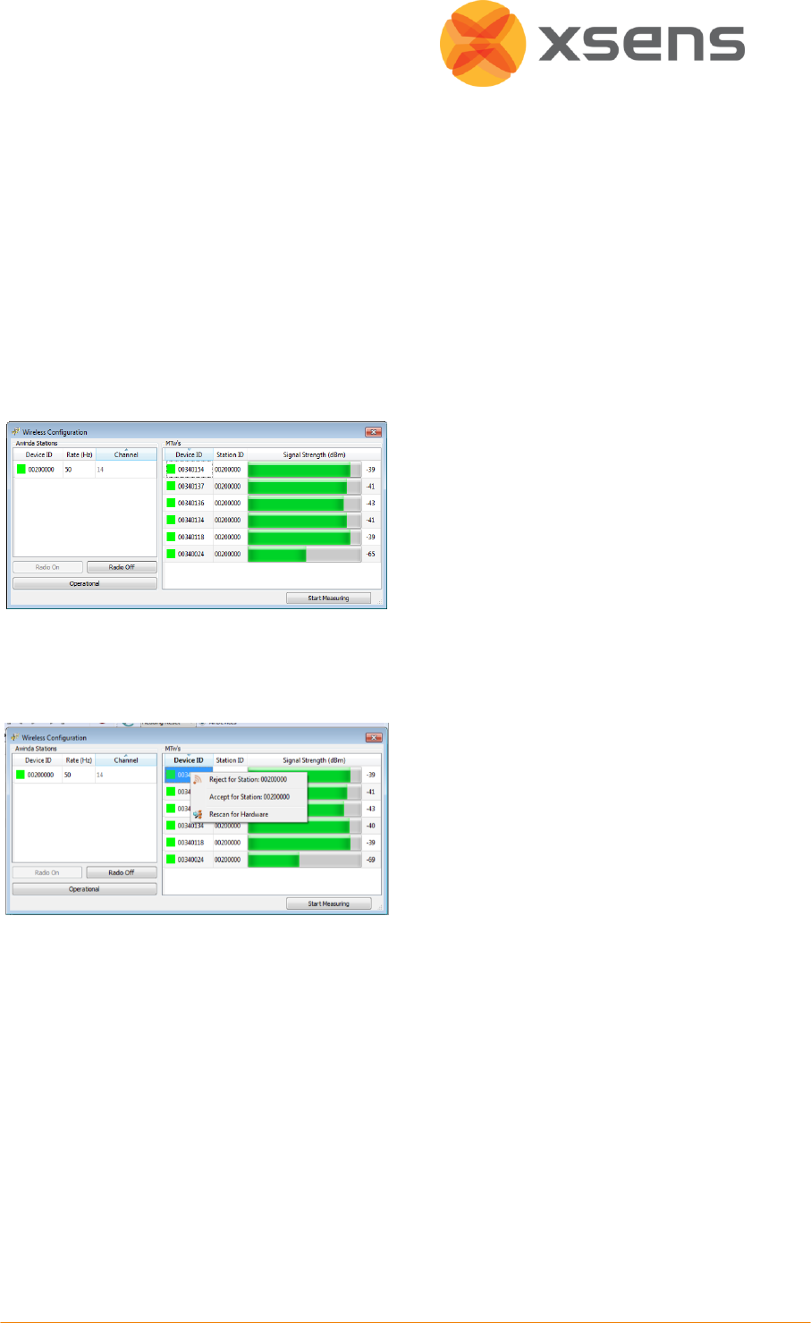
6.5.5 Connecting MTw’s to an Awinda Master
When a connection has been established
between the Awinda Master and the
MTw’s, each MTw appears in the list on
the right hand side, with an indication of
the signal strength.
As each new MTw is detected, the
maximum Update Rate (marked as “Rate
(Hz)”) will decrease as appropriate.
The LED on the MTw will blink synchronously with the LED of the Awinda USB Dongle or with
the CONN LED of the Awinda Station, when a successful link has been established.
The user should decide which of the
detected MTw’s to use in the
measurements. To disconnect a given
Awinda Master and an MTw, right click
over the MTw, and select “Reject for
Station: <StationID>”. Where Station ID is
the serial number of the Awinda Master
in use.
© Xsens Technologies B.V.
28
Initially, if a user has rejected the MTw for a given station, this is depicted as “Unknown”. A
rescan shows that the MTw was rejected by the user “Blacklisted”.
To reconnect a rejected MTw and Awinda Master, right-click the MTw and select “Accept for
Station: <Station ID>”.
Rejecting an MTw does not cause it to power off; it stops communication between that MTw
and the Awinda Master.
NOTE: To power off the MTw, the user should power it off in the Device List, while docked in
the Awinda Station, before starting the wireless configuration. See Section 6.4.1.
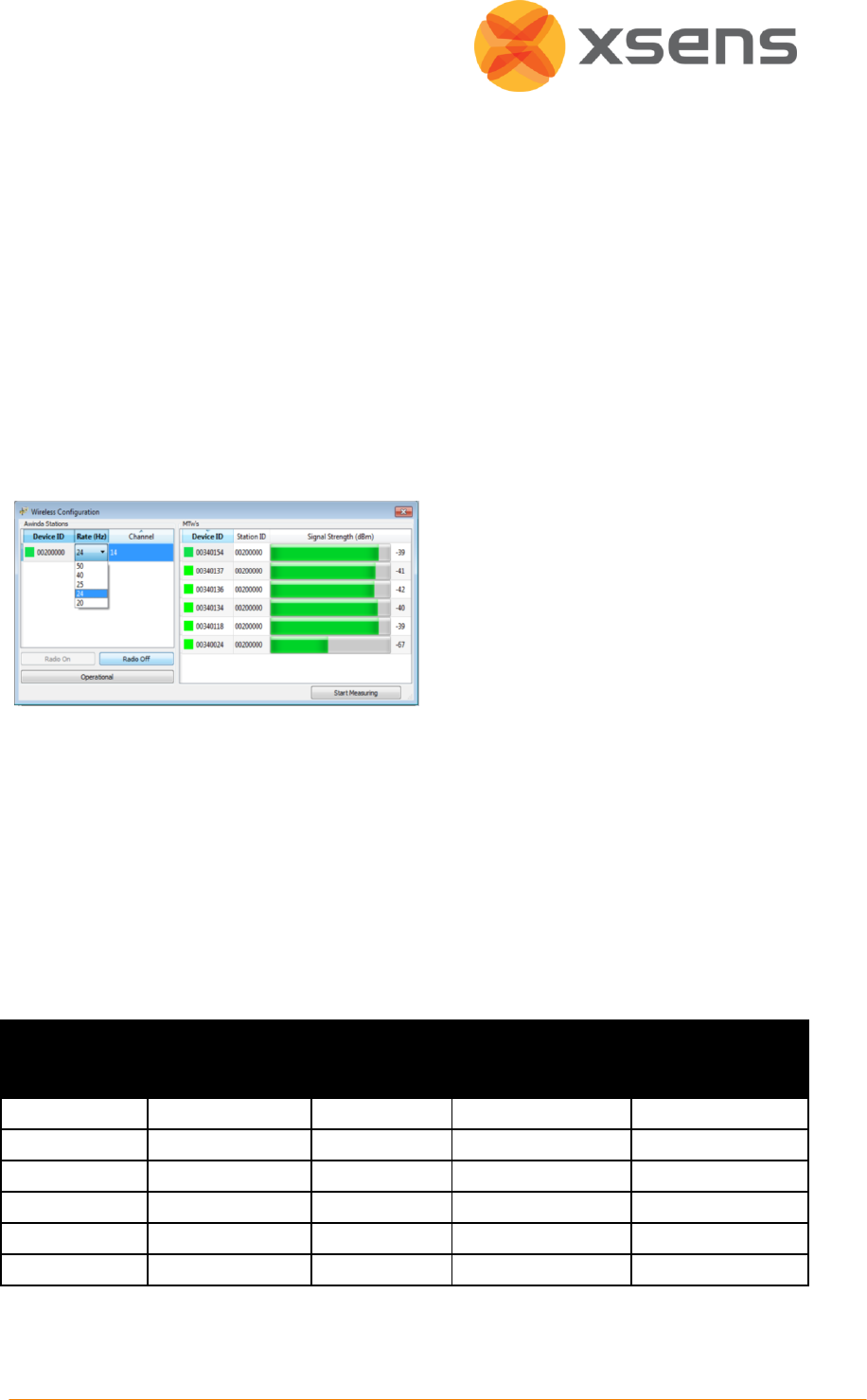
6.5.6 Update Rate
As each MTw makes a connection with
the Awinda Master, the Maximum
Update Rate decreases accordingly.
It is possible to select an update rate, by
double clicking the value under “Rate
(Hz)”, a drop down menu will appear with
the available update rates.
NOTE: The default update rate is always one value less than the maximum, to ensure that
retransmissions are possible during recording. Users can increase this to maximum but
caution should be taken as this will reduce or remove the possibility of retransmissions.
Table 1 provides an indication of the maximum and typical update rates for a number of
MTw’s. The buffering time is also indicated. This is the amount of time that data can be
expected to be stored on the MTw, if the user goes beyond the specified radio transmission
range.
Table 1: Typical and maximum update rates and buffering times
Amount of
MTw’s
UR [Hz]
(max – no
retransmissions)
Buffering
time[s]
(max)
UR [Hz]
(typical – allowing
retransmissions)
Buffering Time [s]
(typ)
1
150
7
120
9
2
120
9
100
10
4
100
10
75
14
6
75
14
60
17
12
50
20
40
26
18
40
26
30
34

© Xsens Technologies B.V.
29
6.5.7 Wireless Connection with the Awinda USB Dongle
The procedure to connect to the Awinda USB Dongle is the same as connecting to the
Awinda Station. Therefore, follow the steps described above. One possible scenario when
using the Dongle is that it is possible that both the Station and the Dongle (therefore two
Awinda Masters) are connected to the PC via the USB port. If only a wireless connection with
the Dongle is needed, then ensure that the radio of the <Station ID> of the Dongle is
activated during the wireless configuration procedure.
6.5.8 Wirelessly Connecting More Than One Awinda Master
If more than one Awinda Master is in use, the user should first configure the MTw’s of one
Master, then click “Operational” to enter operational mode and ensure that the configured
MTw’s are bound to that Awinda Station. When in operational mode, no new MTw’s can be
added to the wireless network. Before configuring the second Awinda Station, first ensure
that the radio channel is different from the previously configured Station, then proceed with
wireless configuration of the second Station.
6.5.9 Operational and Measurement Modes
When only one Awinda Station is in use, when all MTw’s have been detected and accepted
for the measurement, the user can go directly to recordings, the user does not need to
select “Operational” but can go directly to “Start Measuring”.
With Start Measuring command, MT Manager will close the wireless configuration menu,
rescan the COM ports and update the Device List. Remember to keep MTw’s very still at this
time.
The MTw’s are now detected as clients of the active wireless motion tracker network with
the Awinda Station as the master device, as shown in the Device List. All MTw’s are time
synchronised with each other to a global time base given by the Awinda Station.
© Xsens Technologies B.V.
30
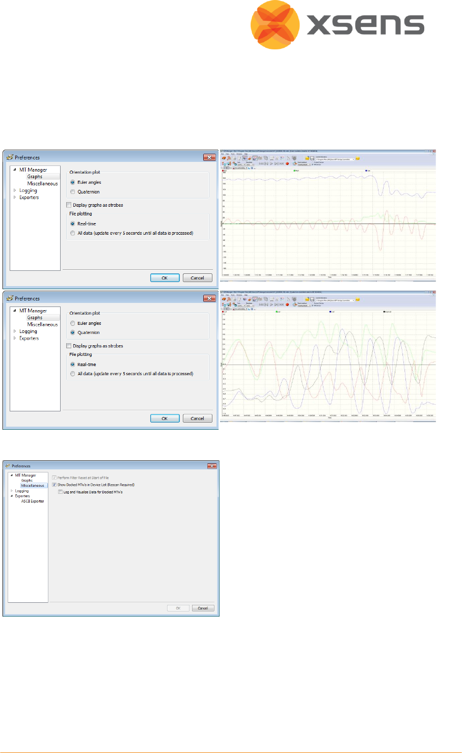
6.6 Preferences
The graphs can be visualised as either Euler angles or quaternions. For more information
about quaternions and Euler angles, see Section 11.7.
6.6.1 Preferences: Graphs
6.6.2 Preferences: Miscellaneous
Show docked MTw’s in Device List (see
6.4).
Log and visualize data for docked MTw’s
(see 6.6.2.2).
© Xsens Technologies B.V.
31
6.6.2.1 Show Docked MTw’s in Device List
This is related to how the Device List handles docked MTw’s. The default setting is to show
docked MTw’s, at all times. If checked (default), docked, and powered on MTw’s will appear
in the Device List, even after wireless configuration. In the Device List it will be possible to
power off, and to observe the battery level of docked MTw’s. If unchecked, after a wireless
configuration, docked MTw’s will not appear in the Device List.
6.6.2.2 Log and Visualize Data for Docked MTw’s
This setting is related to how the recording function handles docked MTw’s. The default
setting is unchecked, which means that data will not be recorded from docked MTw’s. If
checked, data from docked, and powered on MTw’s will be stored in the data files. This may
be useful for users wishing to use for example only the barometer signal from the docked
MTw’s, without using battery power.
Note: If this option is selected, the update rate of these MTw’s is always 100Hz.
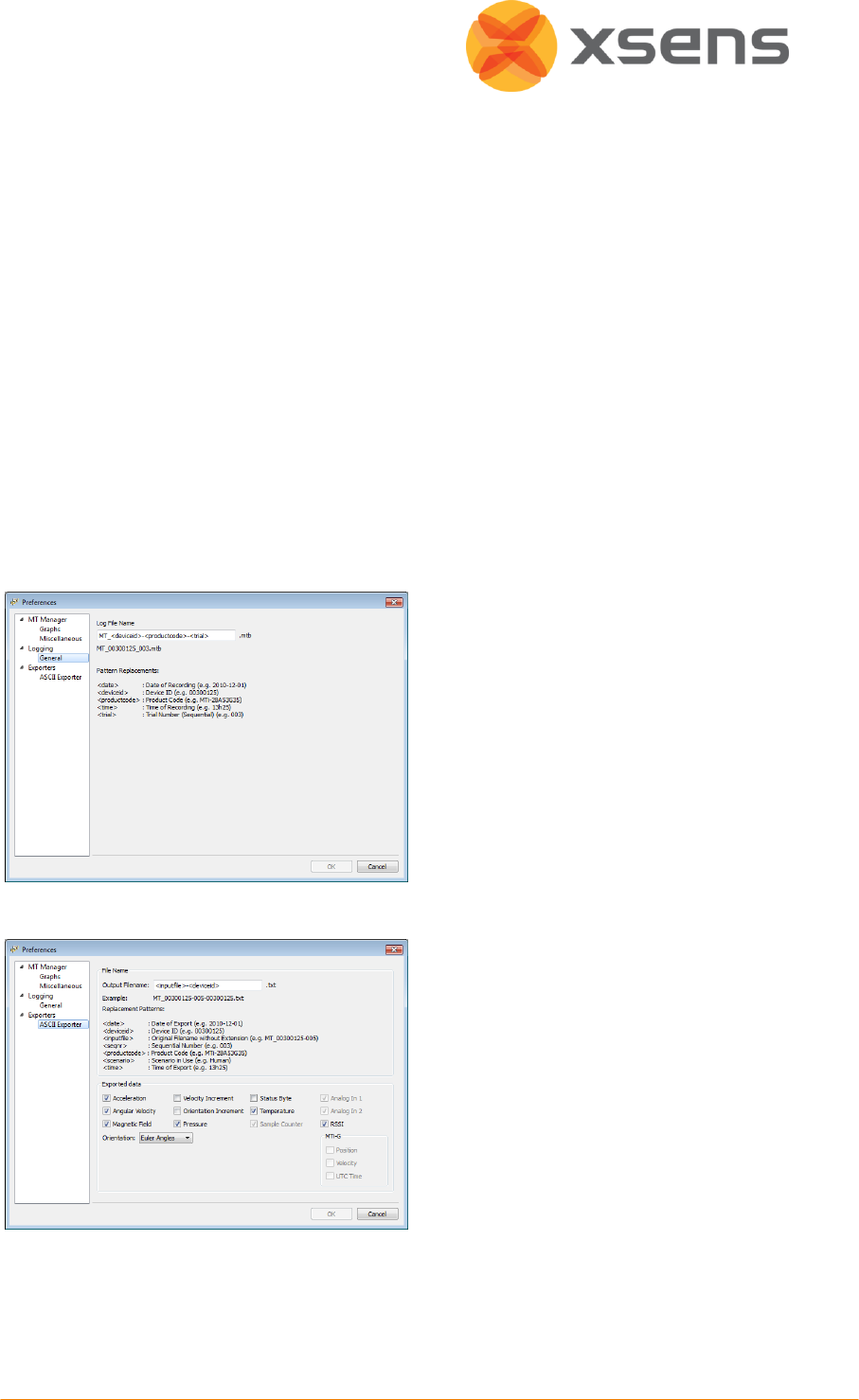
6.6.3 Preferences: Logging
Logging/file names.
It is possible to change the naming in
which the log files are saved.
The Xsens default (and recommended) is
“MT_” followed by the device ID and trial
number. However the user may input
custom text, as well as preset values, such
as date, time etc.
6.6.4 Preferences: Exporters
Following a measurement, it is possible to
export the values. Section 11.7 provides a
description of each Orientation Output
Mode.
Note:
1) Acceleration and Angular Velocity are
values derived from the SDI values.
2) Orientation is always exported, as
default. To undo this, select “none” from
the drop-down menu in the list.
6.7 Synchronisation
MT Manager for MTw provides a very easy to use interface, with many possibilities to
facilitate all kinds of synchronisation with third party devices. The user should decide which
© Xsens Technologies B.V.
32
type of synchronisation to implement, based on the synchronisation possibilities of their
own systems. For synchronisation, one system must be in control, therefore sends the
synchronisation signal (Master/Sync Out), and the other attached systems are controlled by
and receive this signal (Slave/Sync In).
The hardware clock of the Awinda Station is very accurate. As an indication of the clock
accuracy, the error in the Awinda Station’s clock has a maximum of 1 µs every second (1
ppm).
Therefore, in general, the recommended scenario is that Xsens is the master sending the
control signals during synchronisation.
There are four synchronisation ports on the Awinda Station, onto which BNC connectors can
be attached. Two sync ports (Line 1 and Line 2) are available for Sync In and two for Sync
Out. For each synchronisation port, there are a number of possible synchronisation
possibilities.
See Section 11.8 for synchronisation examples.
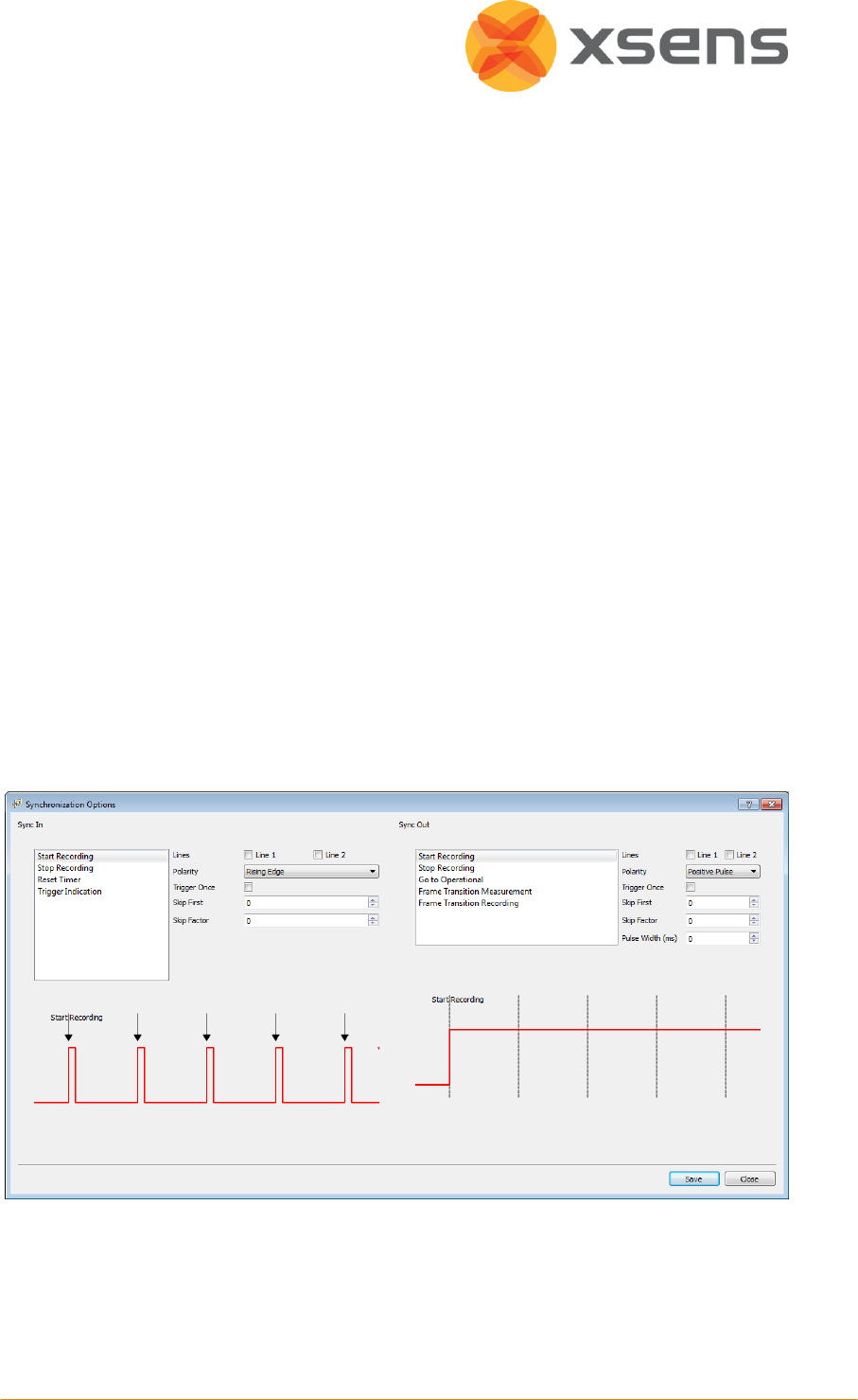
6.7.1 Synchronisation Settings in MT Manager
NOTE: Set the synchronisation settings before carrying out the wireless configuration step.
NOTE: It is not possible to set synchronisation settings during a wireless connection.
To configure the software for synchronisation control, go to >Tools, >Synchronisation
Configuration.
© Xsens Technologies B.V.
33
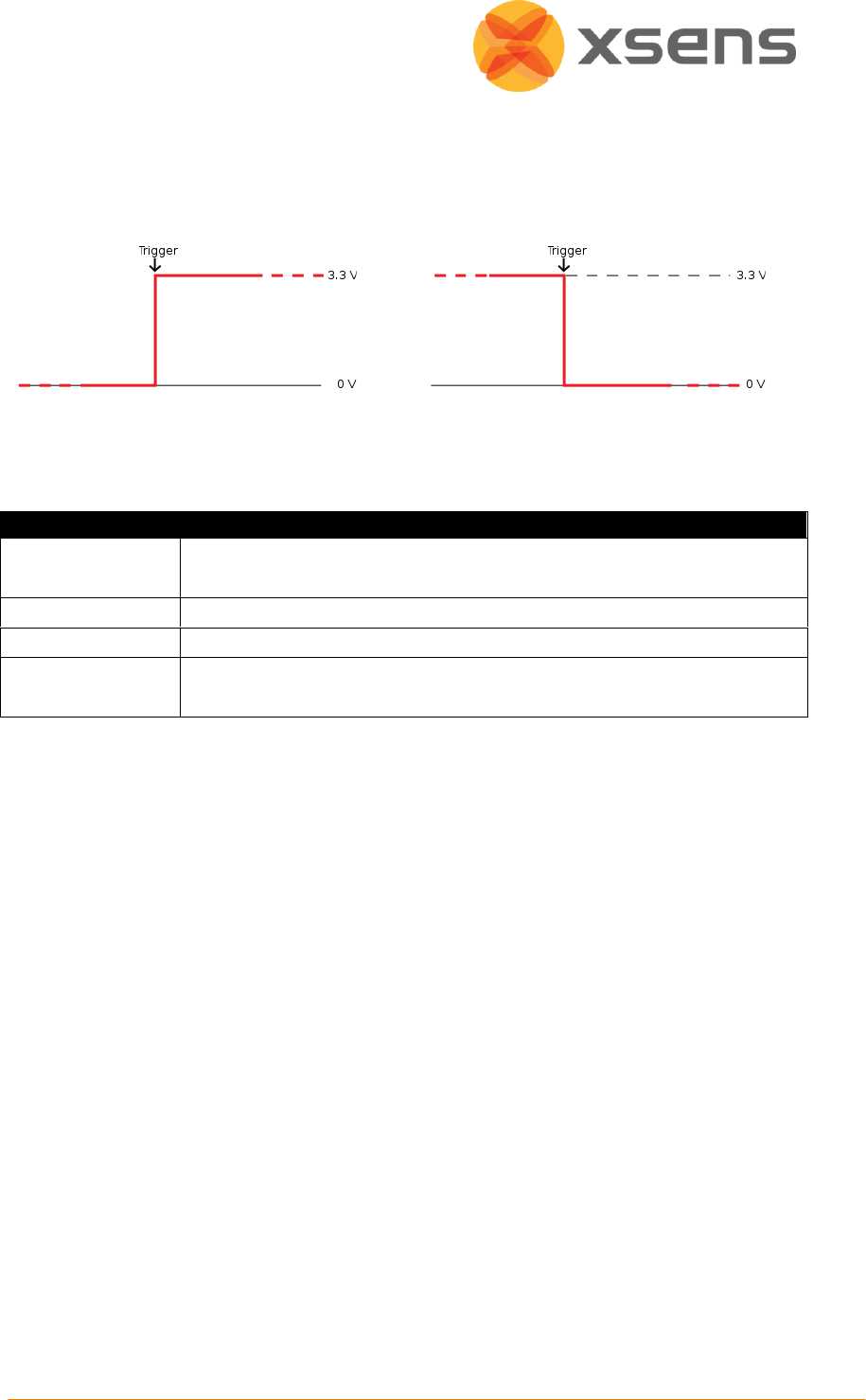
6.7.2 Sync In
Sync In means that a third party device sends a control signal to the Awinda Station. The
Awinda station can detect polarity changes on the input lines. This trigger may be a rising or
falling edge as illustrated in the following figures:
When a trigger is detected on one of the input lines, the Awinda station can be configured to
perform a certain action. A combination of any of the following are possible, on each Sync In
port:
Event
Description
Start Recording
External system sends a start recording trigger. On the Awinda Station,
this will be the next frame.
Stop Recording
External system sends a stop recording trigger.
Reset Timer
The outgoing timer of the Awinda station will be set to 0.
Trigger Indication
The Awinda Station receives a generic signal, determines the
timestamp of a trigger and sends it to MT Manager.
A number of parameters can be set for each action:

© Xsens Technologies B.V.
34
Parameter
Description
Line
The sync line to activate.
Polarity
Rising or falling edge, or rising and falling.
Trigger Once
It is not recommended to selected Trigger once, if more than one
recording using synchronisation of multiple systems will be made.
Skip First
The number of initial occurrences of the sync trigger to skip. This is
useful if a well-defined delay is expected, or if the external signal sends
the same signal to generate both a start and stop recording. Take for
example the command to start recording and stop recording, one
signal sent to the Awinda Station can generate two different
commands. Therefore if both start and stop are on the same sync line,
skip first should be 1 for stop recording, ensuring that the second
trigger, not the first, causes recording to stop.
Skip Factor
The number of occurrences of the sync trigger to skip in between
trigger signals. In the same way that was described in Skip First (above),
skip factor, for start and stop recording on one sync line should be set
to 1, to ensure that the first trigger starts the recording and the second
stops etc.
6.7.3 Important Notices for Sync In
When the Awinda Station is configured to start recording upon receipt of a trigger, it
initialises recording at the start of the following frame. The Awinda Station cannot trigger a
start recording command between frames since data received in a given frame is measured
in the previous one. Therefore, delaying the recording in this way ensures that data is not
recorded prior to the external trigger indication.
Recording should not be stopped between frames, since data received in a given frame was
measured during the previous frame. Therefore, the Awinda Station stops recording
immediately after the current frame.
Rising and falling edge polarity: This command is particularly useful for the ''Trigger
indication'' action for the following purposes:
An external system is connected and the behaviour with respect to its output signals is not
exactly known. The Awinda system can be configured to send a trigger indication to the
driver at every change of polarity. The user can then set the Awinda system to record and
log the incoming trigger indications (only one MTw is required). These logs can be correlated
with the actual actions performed.
Another useful example is to detect when a switch action occurs. An example can be a foot-
switch. A configured trigger indication with rising and falling edge sensitivity could detect
this.

© Xsens Technologies B.V.
35
6.7.3.1 Sync In in MT Manager:
When Sync In is in use, after configuration, and when ready to record, users should click
Record, to prepare the system for the external trigger. The record icon changes from the
normal red dot to one with the pause symbol overlaid:
6.7.4 Sync Out
Sync Out is the command that enable the Xsens system to send a trigger pulse for
synchronisation purposes. A control signal is sent via the Awinda Station, from MT Manager
to the third party hardware. As with sync In, a combination of events are possible, based on
a number of parameters.
Event
Description
Start Recording
Upon clicking the record button in MT Manager, the Awinda Station
starts the recording and consequently sends a start recording trigger to
the third party system.
Stop Recording
Upon clicking the record button in MT Manager, the Awinda Station
stops recording and sends a stop recording trigger to the third party
system.
Go to Operational
This feature gives the maximum flexibility because it speeds up the
preparation of the instrumentation and the subject (if synchronising at
the time of the operational mode) or, once the preparation is done, to
synchronize and record data only when strictly necessary (if
synchronising every time you record)
Frame Transition
Measurement
A frame transition at the station can be used to give a signal to the
external system, indicating the end of the strap-down integration
interval over which data is calculated. Selecting this option, the frame
transition is sent from the moment that “Start Measuring” is selected.
Frame Transition
Recording
See Frame transition Measurement
Selecting this option, the frame transition is sent from the moment
that a recording is started. This is a very useful option to implement, to
ensure that during a recording, the clocks of the synchronised systems
are known, ensuring that any drift can be compensated for.
The default polarity of the output line is low. However, for input triggers that assume high
polarity, the polarity of the line must be set beforehand. This is possible, using 'Go to
operational' with a polarity positive pulse and infinite pulse-width.
A number of parameters can be set for each action:

© Xsens Technologies B.V.
36
Parameter
Description
Line
The sync line to activate.
Polarity
Positive pulse (where the polarity is initially low [0V] and goes high
[3.3V]).
Negative pulse (where polarity is initially high [3.3V] and goes low
[0V]).
Trigger Once
It is not recommended to selected Trigger once, if more than one
recording using synchronisation of multiple systems will be made.
Skip First
Number of initial sync pulses to skip. This command is useful if a well-
defined delay is expected between the Xsens and the third party
system. It may also be needed if the third party, like the Xsens system
uses the same pulse properties to trigger different actions. See
description provided above for Sync In.
Skip Factor
Number of sync pulses, between the sync pulses delivered, to skip. See
Sync In Table description.
Pulse Width
Some systems wait for a signal of a minimum pulse width before
generating the desired synchronisation action. The Awinda Station can
send a pulse with a duration of up to 99ms to a third party system. It is
not recommended to send a signal longer than a frame width.
Specify 0 ms to generate an infinite pulse width.
6.8 Orientation Reset
In some situations, it may occur that the MTw sensor axes are not exactly aligned with the
axes of the object of which the orientation has to be recorded. It may be desired to output
the orientation and/or calibrated inertial (and magnetic) data in an object-fixed frame, as
opposed to a sensor-fixed frame. Four methods have been added to the software to
facilitate in obtaining the output in the desired coordinate frames.
1. Setting an arbitrary rotation matrix to rotate S to the chosen object coordinate system
O. See Section 11.6.3.
2. A heading reset that redefines the X-axis of the global coordinate frame while
maintaining the Z-axis along the vertical (also known as “boresighting”). After the
heading reset the orientation will be expressed with respect to the new global (earth
fixed) reference frame. See Section 11.6.4
3. An object reset that defines how the MTw is oriented with respect to the coordinate
axes to which it is attached. After the object reset, both the inertial (and magnetic) and
orientation data are expressed with respect to the axes of the object. See Section 11.6.5.
4. A combined object/heading reset, referred to as alignment. See Section 11.6.6.
NOTE: For all co-ordinate system reset functions it is important to remember that the
housing of the MTw cannot be considered an accurate reference. Placement and subsequent
aligning must be done very carefully otherwise (alignment) errors may be induced.
© Xsens Technologies B.V.
37
The Orientation Reset menu allows the orientation of the MTw to be reset in a
number of ways. To reset the MTw, align it in the correct manner and select the type of
reset needed from the drop-down menu beside the icon indicated above. Determine if the
reset should be applied to one or all MTw’s. If the reset should be applied to only one MTw,
select the MTw to be reset from the Device List, select the “Current Device” radio button,
then click the reset button.
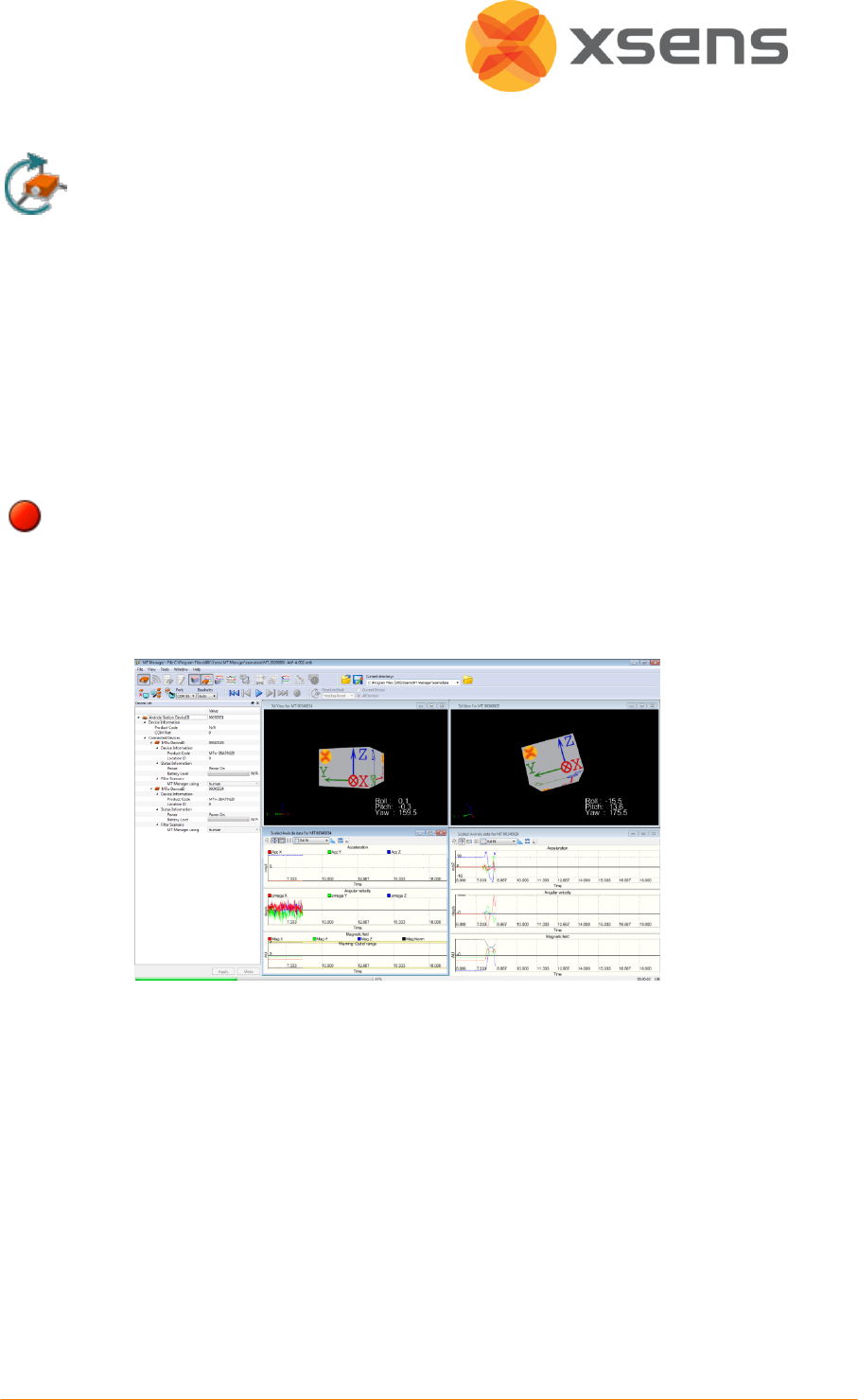
6.9 Recording Data
Before recording data, ensure that the directory stated in the File Control menu is correct.
To record data, use the red icon in the Recording & Playback menu.
Record button in the Playback & Recording menu
When the data is recording the icon appears depressed. To stop the recording, click the
same icon. Data is automatically saved in the directory specified. The record button will be
depressed until all data is downloaded (flushed) from the trackers.
To review the data, graphically, open the .MTB file, open the desired type of graph (inertial,
or orientation data) and select the “Play” icon in the Playback & Recording menu. The
progress of the recorded file during playback is seen in the green progress bar at the bottom
left-hand-side of the screen.
6.10 Saved and Exported Data
MT Manager can export data logged in .MTB files to ASCII format, with the following
content:
Sample Counter – is always exported to ensure that data from all MTw’s are correctly
allocated.

© Xsens Technologies B.V.
38
SDI data (Velocity Increment, Orientation Increment). See Section 11.5 for more
information.
Inertial (and magnetic) calibrated sensor data (3D acceleration, angular velocity,
magnetic field, pressure). Please note that while the terminology is inertial data, the
data received by MT Manager for the accelerometers and gyroscopes are actually data
from the SDI. This means integrated values. This data has been converted to calibrated
sensor data.
Orientation data
The output orientation can be presented in different conventions:
Unit normalised Quaternions (also known as Euler parameters)
Euler angles: roll, pitch, yaw (XYZ Earth fixed type, also known as Cardan)
Rotation Matrix (Direction Cosine Matrix)
Awinda wireless network properties
RSSI: Received Signal Strength Indicator (It is advised to use this to check what the
signal strength was during measurements)
Trigger In timestamps
Status Byte

© Xsens Technologies B.V.
39
Abbreviation
Data
Unit
Counter
Sample counter
(-), wraps at 65535
Temperature
Temperature inside housing
o C
VelInc_X
Velocity increment from SDI, x-axis
m/s
VelInc_Y
Velocity increment from SDI, y-axis
m/s
VelInc_Z
Velocity increment from SDI, z-axis
m/s
OriInc_w
Orientation increment quaternion from SDI, real
component
Unit quaternion
OriInc_x
Orientation increment quaternion from SDI, x-
axis
Unit quaternion
OriInc_y
Orientation increment quaternion from SDI, y-
axis
Unit quaternion
OriInc_z
Orientation increment quaternion from SDI, z-
axis
Unit quaternion
Acc_X
Acceleration x-axis
m/s2
Acc_Y
Acceleration y-axis
m/s2
Acc_Z
Acceleration z-axis
m/s2
Gyr_X
Angular rate x-axis
rad/s
Gyr_Y
Angular rate y-axis
rad/s
Gyr_Z
Angular rate z-axis
rad/s
Mag_X
Magnetic field x-axis
arbitrary unit; magnetic
field strength at Xsens is
1
Mag_Y
Magnetic field y-axis
arbitrary unit; magnetic
field strength at Xsens is
1
Mag_Z
Magnetic field z-axis
arbitrary unit; magnetic
field strength at Xsens is
1
Pressure
Atmospheric pressure
mBar
Roll/Pitch/Yaw
Orientation Euler angles format (3)
deg
Quat *
Orientation quaternion format (4)
Unit quaternion
Mat [R#][C#]
Rotation matrix format [Row][Column] (3x3).
(Direction Cosine matrix)
Unit vectors
Trigger In 1
Awinda converted time stamp values of trigger
indications sent to Sync In 1 of the Awinda
Station
Milliseconds
Trigger In 2
Awinda converted time stamp values of trigger
indications sent to Sync In 2 of the Awinda
Station
Milliseconds
Status
N/A for MTw and / or MT SDK 3.7 Beta
RSSI
Received Signal Strength Indicator by Station
dBm

© Xsens Technologies B.V.
40
Abbreviation
Data
Unit
from each connected MTw
6.11 Application Software Development for the MTw
The MT Manager Windows® GUI application software created by Xsens uses exactly the
same SDK/API available to developers (xsens_cmt.dll) with the dynamic library interface.
This is the same API that is provided for software development in the Software Development
Kit (SDK). Source code for the lower levels of the API (drivers) are supplied for reference but
are not recommended to use for application development on Windows or Linux.
Static LIBs as well as DLLs are provided for developers for both 32-bit and 64-bit platforms.
The DLL also includes a COM interface for easy application development in applications that
support the COM-interface, such as MATLAB, Excel, LabVIEW etc.
For detailed documentation on the API please refer to the Application Programming
Interface (API) reference documentation made available as HTML and the supplied example
source code for C++, C#, LabVIEW and MATLAB.
From MT SDK 3.8 there is also a Linux version of the SDK.

© Xsens Technologies B.V.
41
7 Xsens Peripheral Software
7.1 Magnetic Field Mapper (MFM)
When an MTw is mounted to an object that contains ferromagnetic materials, the measured
(Earth) magnetic field can become distorted, causing errors in measured orientation. To
correct for known magnetic disturbances, for example, an MTw attached to a steel
prosthesis, a separate software product has been developed to allow users to remap the
magnetic field of the MTw. This software is called Magnetic Field Mapper (MFM) and is
located in the installation file of MT Manager. In this directory is also a user manual for
instructions on how to execute MFM, in terms of software steps and how to orientate the
MTw during the process. The user manual for the MFM is generic since it is useful for all
Xsens products.
First create a wireless connection for the given MTw (see Section 6.4.2, but pay particular
attention to the instructions below):
Note: MFM can be run for one MTw at a time. Therefore for each MTw that should be
mapped, use the following instructions, 1-3 depends on user preference, 4-10 applies to
both methods of choice.
In MT Manager do the following:
Power off unnecessary MTw’s
Wirelessly reject unnecessary MTw’s
1
Dock all MTw’s
Undock all MTw’s
2
Power off all but one MTw in the device
list
Wireless configuration
3
Wireless configuration for remaining MTw
Reject all but one MTw
4
Set update rate to 100Hz
5
Start Measuring
6
Close MT Manager
7
Activate MFM
8
Follow instructions for MFM
9
Close MFM
10
Repeat above for remaining MTw’s to be mapped.
7.2 Firmware Updater
With new software releases, it can be expected that new firmware is required for the
Awinda Station, Awinda USB Dongle and MTw’s. Xsens supplies a firmware updater. The
firmware updater is found in START> All Programs > Xsens > Firmware Updater.

© Xsens Technologies B.V.
42
It is important to select Awinda system and to follow the on-screen instructions. There are
step by step instructions in the user manual. START > All Programs > Xsens >Documentation
>Firmware Updater User Manual.
Note that the maximum amount of devices that the firmware updater can handle for an
MTw system, is 16 devices. In theory this can be two MTw kits comprising for example:
2x Awinda Stations
2x Awinda USB Dongles
12x MTw’s (6 docked in each Awinda Station).

© Xsens Technologies B.V.
43
8 Troubleshooting and Support
Problem
Possible cause
Solution
Installation is
aborted due to
previously installed
version.
Drivers are still present from the
previous Xsens MT SDK
installations.
Use Add/Remove Programs on
the Control Panel to remove the
previously installed version.
Then re-try installing the desired
version.
After Wireless
configuration MTw
appears to spin.
Too much movement when
entering measurement mode.
Filter not initialised correctly.
Keep motion trackers as still as
possible when entering
measurement mode from
wireless configuration. See
Settling Time (Section 3.3.2) for
details.
Rescan ports to reinitialise the
filters.
The MTw is no
longer visible in the
Device List.
It is possible that MTw’s have
been removed and replaced too
quickly in the Awinda Station,
therefore no longer recognised in
MT Manager.
MTw is powered off.
Place the MTw into another
station socket.
Note: When the MTw is left
unplugged for a while (few
minutes), the MT Manager will
find it again.
COM ports have
been scanned, but
no devices
detected.
It is possible that an incorrect
baudrate has been selected; this
means that the device cannot be
found.
Select “Auto” in the baudrate
drop down menu. Then rescan all
COM ports.
No Awinda
Station/MTw’s
found by MT
Manager.
The host PC/laptop may not have
properly installed the USB drivers
for the Awinda Station.
Check all cable connections. Un-
plug the USB cable and power
supply from the Awinda Station,
close MT Manager. Wait 30
seconds and then re-plug and
reopen MT Manager.
Awinda Station
“freezes”.
A corruption has occurred in the
USB driver between the Awinda
Station and the PC.
Unplug the USB cable and power
supply from the Awinda Station,
close MT Manager. Wait 30
seconds and then re-plug and
reopen MT Manager.
Following rescan, no
Awinda Station, and
/or fewer than
expected MTw’s
Check all cable connections.
Un-plug the USB cable and power
supply from the Awinda Station,
wait 30 seconds and then re-plug

© Xsens Technologies B.V.
44
Problem
Possible cause
Solution
found in the Device
List.
it.
Re-entering wireless
network after out of
range, MTw(s) not
detected in MTM.
MTw and Awinda Station lost
wireless connection for an
undesired length of time.
Re-dock the MTw(s) perform
Wireless configuration step again
(Section 6.4.2).
Re-enable radio
does not always
find trackers used
before.
Re-dock the MTw(s), rescan ports
and perform Wireless
configuration step again (Section
6.4.2).
RSSI in Wireless
configuration is full,
while I cannot
receive data from
the MTw.
MTw and Awinda Station no
longer wirelessly connected.
Re-dock the MTw(s) perform
Wireless configuration step again
(Section 6.4.2).
MTw in Wireless
Configuration is
shown as
disconnected, but
RSSI appears to
have a good
strength.
MTw and Awinda Station are not
wirelessly connected.
Related to above issue.
Re-dock the MTw(s), rescan ports
and perform Wireless
configuration step again (Section
6.4.2).
A discrepancy of a
sample count is
detected between
MTw’s at the
beginning or end of
an exported file.
Due to the nature of wireless
transmission, this may occur.
Always allocate exported data to
a given sample count.
NB - also to prevent possible
problems of missing samples.

© Xsens Technologies B.V.
45
8.1 Customer Support
Xsens Technologies B.V. is glad to help you with any questions you may have about the
MTw, or about the use of the technology for your application. Please use the FAQ or contact
Xsens Customer Support:
Internet and FAQ: http://www.xsens.com/support
Telephone: Xsens HQ +31 88 97367 00 / Xsens US office 310-481-1800
To be able to help you, please mention your Motion Tracker Device ID (on the back of the
device) and software license registration number in your e-mail.

© Xsens Technologies B.V.
46
9 Warranty Liability
Xsens Technologies B.V. warrants the products manufactured by it to be free from defects in
material and workmanship for a period of 1 year from the date of delivery. Products not
subjected to misuse will be repaired, replaced or credit issued at the sole option of Xsens
Technologies B.V. Contact Xsens via www.xsens.com/support for return material
authorization (RMA) prior to returning any items for calibration, repair or exchange. The
product must be returned in its original packaging to prevent damage during shipping.
The warranty shall not apply to products repaired or altered or removed from the original
casing by others than Xsens Technologies B.V. so as, in Xsens Technologies B.V. opinion, to
have adversely affected the product, products subjected to negligence, accidents or
damaged by circumstances beyond Xsens Technologies B.V.’s control.
NOTE: Xsens reserves the right to make changes in its products in order to improve design,
performance, or reliability.
Subject to the conditions and limitations on liability stated herein, Xsens warrants that the
Product as so delivered shall materially conform to Xsens’ then current specifications for the
Product, for a period of one year from the date of delivery. ANY LIABILITY OF XSENS WITH
RESPECT TO THE SYSTEM OR THE PERFORMANCE THEREOF UNDER ANY WARRANTY,
NEGLIGENCE, STRICT LIABILITY OR OTHER THEORY WILL BE LIMITED EXCLUSIVELY TO
PRODUCT REPAIR, REPLACEMENT OR, IF REPLACEMENT IS INADEQUATE AS A REMEDY OR, IN
XSENS' OPINION IMPRACTICAL, TO REFUND THE PRICE PAID FOR THE PRODUCT. XSENS DOES
NOT WARRANT, GUARANTEE, OR MAKE ANY REPRESENTATIONS REGARDING THE USE, OR
THE RESULTS OF THE USE, OF THE PRODUCT OR WRITTEN MATERIALS IN TERMS OF
CORRECTNESS, ACCURACY, RELIABILITY, OR OTHERWISE. Xsens shall have no liability for
delays or failures beyond its reasonable control.

© Xsens Technologies B.V.
47
10 Regulatory Notices
10.1 Radio Frequency Exposure and Emission
The MTw contains a small radio transmitter and receiver. During communication with the
Awinda Station it receives and transmits radio frequency (RF) electromagnetic fields
(microwaves) in the frequency range 2400 of 2500 MHz (IEEE 802.15.4 PHY compliant). The
output power of the radio transmitter is very low. When using the system, you will be
exposed to some of the transmitted RF energy. This exposure is well below the prescribed
limits in all national and international RF safety standards and regulations.
Most modern electronic equipment, for example, in hospitals and cars, is shielded from RF
energy. However, certain electronic equipment is not.
Therefore:
Note: This equipment emits RF energy in the ISM (Industrial, Scientific, Medical) band.
Please insure that all medical devices used in proximity to this device meet appropriate
susceptibility specifications for this type of RF energy (CE or FCC marked).
Turn off this electronic device before entering an area with potentially explosive
atmosphere. It is very rare, but any electronic device could generate sparks. Sparks in such
areas could cause an explosion or fire resulting in bodily injury or even death. Areas with a
potentially explosive atmosphere are often, but not always, clearly marked. They include
fuelling areas, such as petrol station, below deck on boats, fuel or chemical transfer or
storage facilities, and areas where the air contains chemicals or particles, such as grain, dust,
or metal powders.

© Xsens Technologies B.V.
48
10.2 FCC Statement
NOTE: This equipment has been tested and found to comply with the limits for a Class B
digital device, pursuant to Part 15 of the FCC Rules. These limits are designed to provide
reasonable protection against harmful interference in a residential installation. This
equipment generates, uses and can radiate radio frequency energy and, if not installed and
used in accordance with the instructions, may cause harmful interference to radio
communications. However, there is no guarantee that interference will not occur in a
particular installation. If this equipment does cause harmful interference to radio or
television reception, which can be determined by turning the equipment off and on, the user
is encouraged to try to correct the interference by one or more of the following measures:
Reorient or relocate the receiving antenna
Increase the separation between the equipment and receiver
Connect the equipment into an outlet on a circuit different from that to which the
receiver is connected
Consult the dealer or an experienced radio/TV technician for help.

© Xsens Technologies B.V.
49
10.3 CE Declaration of Conformity
We, Xsens Technologies B.V., of
Pantheon 6a
7521 PR Enschede
The Netherlands
declare under our sole responsibility that our product:
MTw-38A##G##
AWNDDNG
AW-A
to which this declaration relates, conforms to the following Standards and other
Normative Documents:
EN 61326-1 (2006)
EN 61326-1 (2006)
EN 61000-3-2 (2006)
EN 61000-3-3 (1995) + A1 (2001) + A2 (2005)
EN 60950-1: 2006 Safety of information technology equipment
Environment to be used is light industrial / laboratory
Class of emission is B.
January 13 2011 Enschede, the Netherlands
Per Slycke
CTO
Xsens Technologies B.V.

© Xsens Technologies B.V.
50
10.4 FCC Declaration of Conformity
We, Xsens Technologies B.V., of
Pantheon 6a
7521 PR Enschede
The Netherlands
declare under our sole responsibility that our product:
MTw-38A##G##
AWNDDNG
AW-A
to which this declaration relates, have been tested and found to comply with the limits
for a Unintentional Radiator as described in 47 CFR 15 (2007 May, 04 Edition) Class B
Digital Device, pursuant to Part 15 of the FCC Rules.
Operation is subject to the following two conditions:
1. This device may not cause harmful interference, and
2. This device must accept any interference received, including interference that may
cause undesired operation.
January 13 2011 Enschede, the Netherlands
Per Slycke
CTO
Xsens Technologies B.V.

© Xsens Technologies B.V.
51
11 Appendices
11.1 MTw Technical Specifications
11.1.1 MTw Performance
Angular velocity
Acceleration
Magnetic field
Pressure
Dimensions
3 axes
3 axes
3 axes
-
Full Scale
± 1200 deg/s
± 160 m/s2
± 1.5 Gauss
300 -1100 mBar1
Linearity
0.1 % of FS
0.2 % of FS
0.2 % of FS
0.05 % of FS
Bias stability 2
20deg/hr
-
-
100 Pa/year
Noise
0.05deg/s/√Hz
0.003m/s2/√Hz
0.15mGauss/√Hz
0.85 Pa/√Hz
Alignment error
0.1 deg
0.1 deg
0.1 deg
-
Bandwidth3
100Hz (max.)
100 Hz (max.)
20 Hz (max.)
-
11.1.2 Orientation Performance
Dynamic Range
all angles in 3D
Angular Resolution4
0.05 deg
Static accuracy
(Roll/Pitch)
<0.5 deg
Static Accuracy5 (Heading)
1 deg
Dynamic Accuracy6
2 deg RMS
11.1.3 MTw Physical Properties
Accelerometers
MEMS solid state, capacitative readout
Rate gyroscope
MEMS solid state, monolithic, beam structure, capacitive readout
Magnetometer
Magneto-Impedance sensor elements
Barometer
Piezo-resistive sensor element
Weight
27g
Housing dimensions
34.5 x 57.8 x 14.5mm (W x L x H)
1
(-500 -.9000 m above sea level)
2
As measured from the Allan variance diagram.
3
Half of the chosen sampling rate.
4
1 σ standard deviation of zero-mean angular random walk
5
In homogenous magnetic environment
6
May depend on type of motion
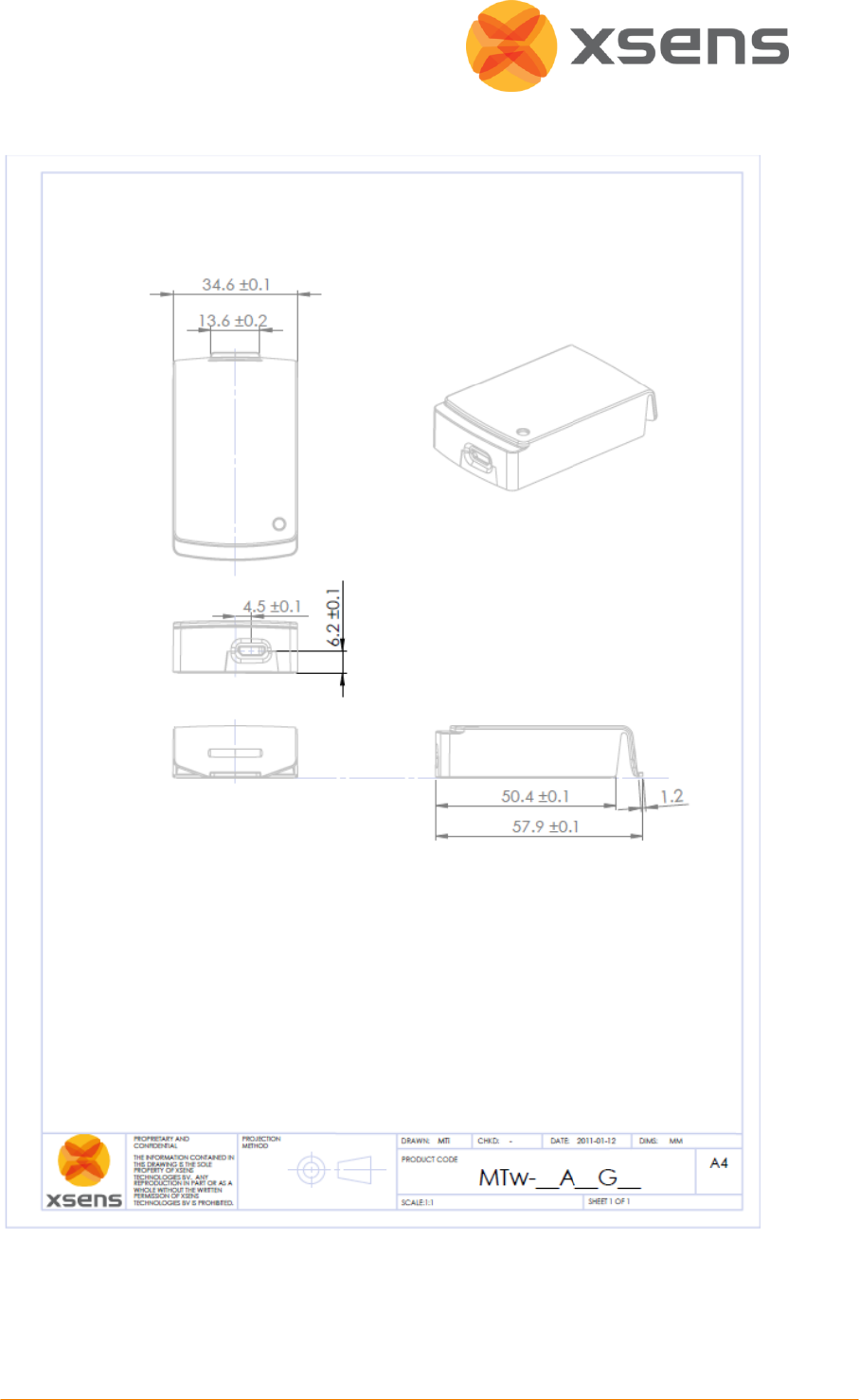
© Xsens Technologies B.V.
52
11.1.4 Schematics MTw Housing Specifications
11.1.5 Charging / Discharging MTw’s
The MTw’s are equipped with LiPo batteries, with a capacity of 220mAh. Fully charged, it has
a run-time of 2.5-3.5hrs, depending on the data rate and temperature. Charging will take
~1hrs at room temperature. Do not exceed charging ambient temperature of 0 °C to +45 °C.

© Xsens Technologies B.V.
53
NOTE: If the MTw isn't used for a long time, please put them away half-charged. Store them
in a cool and dry place
11.2 Awinda Station Technical Specifications
The Awinda Station uses the Awinda protocol to receive and time-synchronize data from up
to 32 MTw’s simultaneously.
Data from multiple MTw’s time-synchronized to within 10µs, with a reasonable radio
link.
Charges up to 6 MTw’s simultaneously.
LED indicators for MTw status.
Synchronisation with third party devices
The Awinda Station has four AUX sync I/O BNC connectors for synchronisation with third
party devices. These have TTL levels of 0-3.3V.
Power supply
A power adapter is shipped with the MTw Development kit, to power the Awinda Station
(necessary for charging the MTw’s). The power adapters have EU/US/UK plugs and electrical
properties: 100-240V AC/12 V DC 1.5A.
Communication
The Awinda Station interfaces with the PC using a USB cable, supplied with the system.
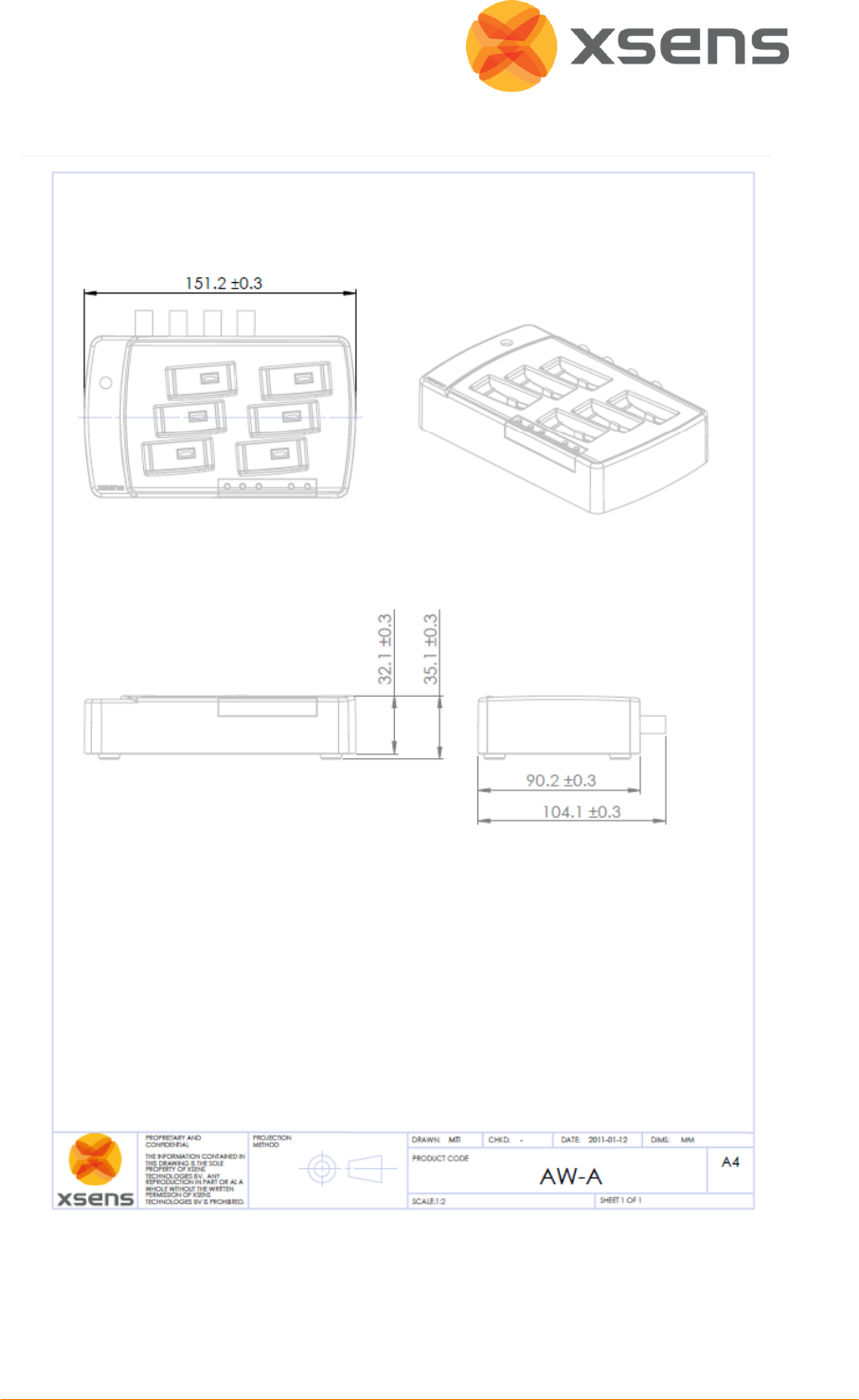
© Xsens Technologies B.V.
54
11.2.1 Schematics Awinda Station Housing Specifications
11.3 Awinda USB Dongle Technical Specifications
The Awinda USB Dongle uses the Awinda protocol to receive and time-synchronize data
from up to 32 MTw’s simultaneously.

© Xsens Technologies B.V.
55
Data from multiple MTw’s time-synchronized to within 10µs, with a reasonable radio
link.
LED indicators for MTw connectivity status.
Power supply
The USB Dongle uses only 440mW therefore does not require external power supply,
meaning that it is ideal for outdoor use.
Communication
The Awinda Station interfaces with the PC using a USB cable, supplied with the system.
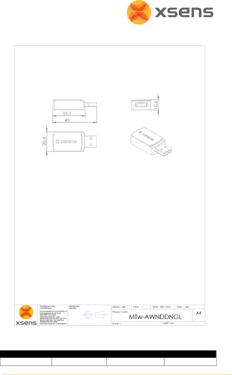
© Xsens Technologies B.V.
56
11.3.1 Schematics Awinda USB Dongle Housing Specifications
11.3.2 Physical, Electrical and RF Properties
MTw
AWINDA Station
Awinda Dongle
Communication
Wireless 2.4GHz/USB
Wireless 2.4GHz/ USB
Wireless 2.4GHz/

© Xsens Technologies B.V.
57
interface
USB
Wireless transmit
range indoor
/outdoor
~20m / 70m
~50m
~20m
Synchronization
accuracy
< 10µs
<1ppm clock drift
<1ppm clock drift
Additional
interfaces:
NA
2 x Sync In (BNC)
2 x Sync Out (BNC)
NA
Operating voltage
4.65-5.25 V
4.65-5.25V / 12V
4.65-5.25V
Power
consumption1
~265 mW
10W max2
< 440mW
Battery runtime
~3-4 hrs3
NA
NA
Charge time
~1 hrs
NA
NA
Temperature
Operating Range
-10oC to 60oC
(discharge)
-20 to 85oC
-20 to 85oC
Specified
performance
Operating
Temperature Range
0oC to 55oC
0 to 55 oC
0 to 55 oC
Housing Dimensions
34.5 x 57.8 x 14.5mm
(W x L x H)
148 x 104 x 61.9 mm (L
x W x H)
Note: Awinda
dimensions with
antenna attached, but
not raised.
45x20.4x10.6mm
with USB connector
33x20.4x10.6mm
without
Weight
27g
200g
8g
1
Power consumption for the MTw depends on the chosen frame rate.
2
Power consumption during charging of 6 empty MTw’s.
3
Battery runtime when fully charged depends on the chosen frame rate and ambient
temperature.

© Xsens Technologies B.V.
58
11.4 Xsens Kalman Filter
The orientation of the MTw is computed by Xsens Kalman Filter for 3 degrees-of-freedom
(3DoF) orientation (XKF-3w). XKF-3w uses signals of the rate gyroscopes, accelerometers and
magnetometers to compute a statistical optimal 3D orientation estimate of high accuracy
with no drift for both static and dynamic movements.
The design of the XKF-3w algorithm can be explained as a sensor fusion algorithm where the
measurement of gravity (by the 3D accelerometers) and Earth magnetic north (by the 3D
magnetometers) compensate for otherwise slowly, but unlimited, increasing (drift) errors
from the integration of rate of turn data (angular velocity from the rate gyros). This type of
drift compensation is often called attitude and heading referenced and such a system is
often called an Attitude and Heading Reference System (AHRS). For the MTw, a specific
Xsens Kalman Filter (XKF-3-w) has been developed to deal with the nature of wireless
transmissions (e.g. irregular updates due to temporal packets losses) and the use of high-
accuracy strap down integration. In-depth documentation/whitepapers will be provided at a
later date. For specific questions, please contact support@xsens.com.
11.4.1 Using the Acceleration of Gravity to Stabilize Inclination (Roll/Pitch)
XKF-3w stabilizes the inclination (i.e. roll and pitch combined, also known as “attitude”)
using the accelerometer signals. An accelerometer measures gravitational acceleration plus
acceleration due to the movement of the object with respect to its surroundings.
XKF-3w uses the assumption that on average the acceleration due to the movement is zero.
Using this assumption, the direction of the gravity can be observed and used to stabilize the
attitude. The orientation of the MT in the gravity field is accounted for so that centripetal
accelerations or asymmetrical movements cannot cause a degraded orientation estimate
performance. This assumption is surprisingly powerful, almost all moving objects undergo
accelerations if they are moving, but in most cases the average acceleration with respect to
the environment during some period of time is zero. The key here is the amount of time over
which the acceleration must be averaged for the assumption to hold. During this time, the
rate gyroscopes must be able to track the orientation to a high degree of accuracy. In
practice, this limits the amount of time over which the assumption holds true. For the class
of miniature MEMS rate gyroscopes used in the MT this period of time is about 10-20
seconds maximum.
However, for some applications this assumption does not hold. For example an accelerating
automobile may generate significant accelerations for time periods lasting longer than the
maximum time the MT’s rate gyroscopes can reliably keep track of the orientation. This will
severely degrade the accuracy of the orientation estimates with XKF-3, because the use
scenario (application) does not match the assumptions made. Note however, that as soon as
the movement does again match the assumptions made, XKF-3w will recover and stabilize.
The recovery to optimal accuracy can take some time.

© Xsens Technologies B.V.
59
NOTE: To be able to accurately measure orientations as well as position in applications
which can encounter long term accelerations, Xsens offers a solution that incorporates a GPS
receiver (the MTi-G).
11.4.2 Using the Earth Magnetic Field to Stabilise Heading (Yaw)
By default, the heading is stabilised using the local (earth) magnetic field. In other words, the
measured magnetic field is used as a compass. If the local Earth magnetic field is temporarily
disturbed, XKF-3w will track this disturbance instead of incorrectly assuming there is no
disturbance. However, in case of structural magnetic disturbance (>10 to 20 s) the computed
heading will slowly converge to a solution using the 'new' local magnetic north. Note that
the magnetic field has no direct effect on the inclination estimate.
If the MTw is rigidly strapped to an object containing ferromagnetic materials, structural
magnetic disturbances will be present. Using an Xsens a technique 'magnetic field mapping'
(i.e. a 3D calibration for soft and hard iron effects), these magnetic disturbances can be
completely accounted for, allowing the MTw to be used as if it would not be secured to an
object containing ferromagnetic materials.
11.4.3 Initialisation
The XKF-3w algorithm not only computes orientation, but also keeps track of variables such
as sensor biases or properties of the local magnetic field. For this reason, the orientation
output may need some time to stabilize once the MTw is put into measurement mode. Time
to obtain optimal stable output depends on a number of factors. An important factor
determining stabilizing time is determined by the time to correct for small errors on the bias
of the rate gyroscopes. The bias of the rate gyroscope may slowly change due to different
effect such as temperature change or exposure to impact. To reduce stabilizing time, the last
computed gyroscope bias can be stored in the sensor unit non-volatile memory. If the MT is
used after only a short period of power-off the gyro biases will generally not have changed a
lot and the stabilizing time will typically be less than 10 seconds. Furthermore, XKF-3w will
converge faster and reach optimal robustness faster if it is started in an area without
magnetic disturbances.
11.5 Strap Down Integration
1
Strap down integration (SDI) is a method used to compute an orientation/position change
given an angular velocity and linear acceleration of a rigid body. Angular velocity and
acceleration data in the MTw is sampled at a very high frequency to maintain accuracy under
very dynamic conditions such as vibrations and impacts. The sampling frequency is too high
to be transmitted wirelessly, and would typically present a computational load that is too
high on the receiving host device (e.g. PC). Therefore the data that has been sampled at a
high frequency is digitally filtered and down-sampled to 600 Hz and calibrated using the
1
Further information about strap down integration for the MTw is available in the MTw
Whitepaper.

© Xsens Technologies B.V.
60
individual device calibration
1
values on the embedded microprocessor (MCU) of the MTw.
Based on this data the MTw further calculates velocity increments and orientation
increments using an SDI algorithm. The main advantage of using the SDI algorithm is that full
3D tracking accuracy can be maintained even if the output update rate from the MTw is very
low (<100 Hz). An additional advantage is that the MTw can continue to track the 3D motion
internally when facing transient data loss in the RF transmission and immediately report the
full 3D velocity and orientation increment as soon as the RF link is restored (data packets
again received by the Awinda Station), without the need to re-transmit all the data that was
lost which would a) cause a large delay during real-time tracking b) use a lot of precious RF
bandwidth and consume unnecessary power. The specific use of SDI data in combination
with such a specialized RF protocol, Xsens has named the Awinda protocol
2
.
NOTE: Velocity and orientation increments resulting from the embedded SDI can easily be
converted back to acceleration and angular velocity values. At high enough update rates
there is no or negligible loss of accuracy due to this conversion. What is “high enough” is
partly also determined by the dynamics of the movement. Xsens recommends the use of SDI
values rather than acceleration and angular velocity values for further calculations as they
represent the highest degree of accuracy.
1
The devices are calibrated at the factory by Xsens and is a highly sophisticated process
compensating for component errors that are not stochastic (i.e. they can be modeled).
Compensation models include bias, gain, misalignment, g sensitivity, temperature effects,
etc.
2
Patents pending.
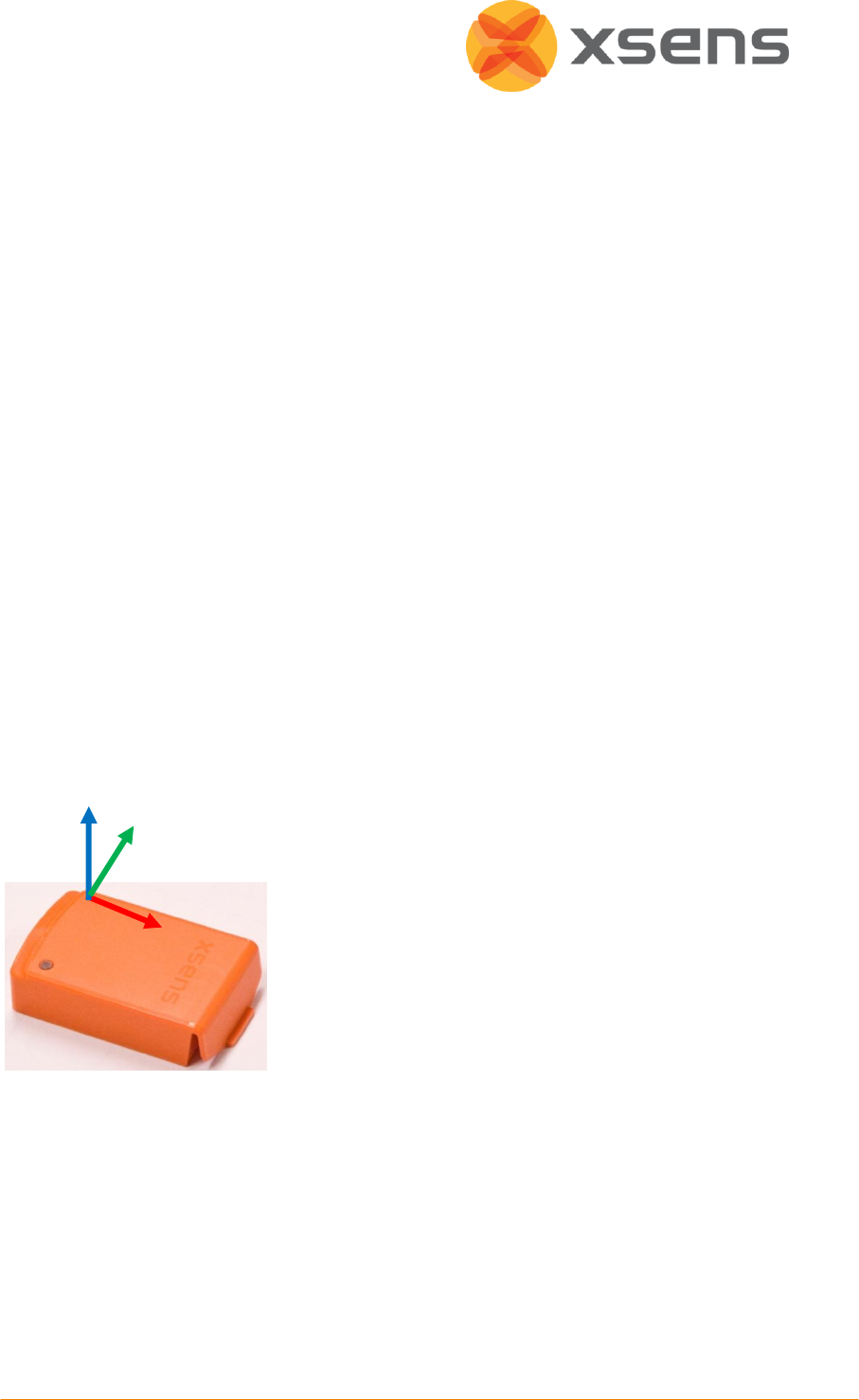
© Xsens Technologies B.V.
61
11.6 Coordinate Systems
11.6.1 Calibrated Sensor Readings
All calibrated sensor readings (accelerations, angular velocity, earth magnetic field, pressure)
are in the right handed Cartesian co-ordinate system as defined in the figure below. This co-
ordinate system is body-fixed to the device and is defined as the sensor co-ordinate system
(S). The 3D orientation output is discussed in Section 11.6.2.
The co-ordinate system is aligned to the external housing of the MTw.
High accuracy alignment between the (plastic) housing and the sensor-fixed output
coordinate system (S) is not possible for the MTw for obvious reasons. The actual alignment
between the S co-ordinate system and the bottom part of the plastic housing is guaranteed
to <3o.
The non-orthogonality between the axes of the body-fixed co-ordinate system, S, is <0.1o.
This also means that the output of 3D linear acceleration, 3D angular velocity (gyro) and 3D
magnetic field data all will have orthogonal XYZ readings within <0.1o.
11.6.2 Orientation Coordinate System
The MTw calculates the orientation between the sensor-fixed co-ordinate system, S, and a
earth-fixed reference co-ordinate system, G. By default, the local earth-fixed reference co-
ordinate system used is defined as a right handed Cartesian co-ordinate system with:
X positive when pointing to the local magnetic North.
Y according to right handed co-ordinates (West).
Z positive when pointing up.
The 3D orientation output (independent of output mode, see Section 11.7) is defined as the
orientation between the body-fixed co-ordinate system, S, and the earth-fixed co-ordinate
system, G, using the earth-fixed co-ordinate system, G, as the reference co-ordinate system.
Z
Y
X
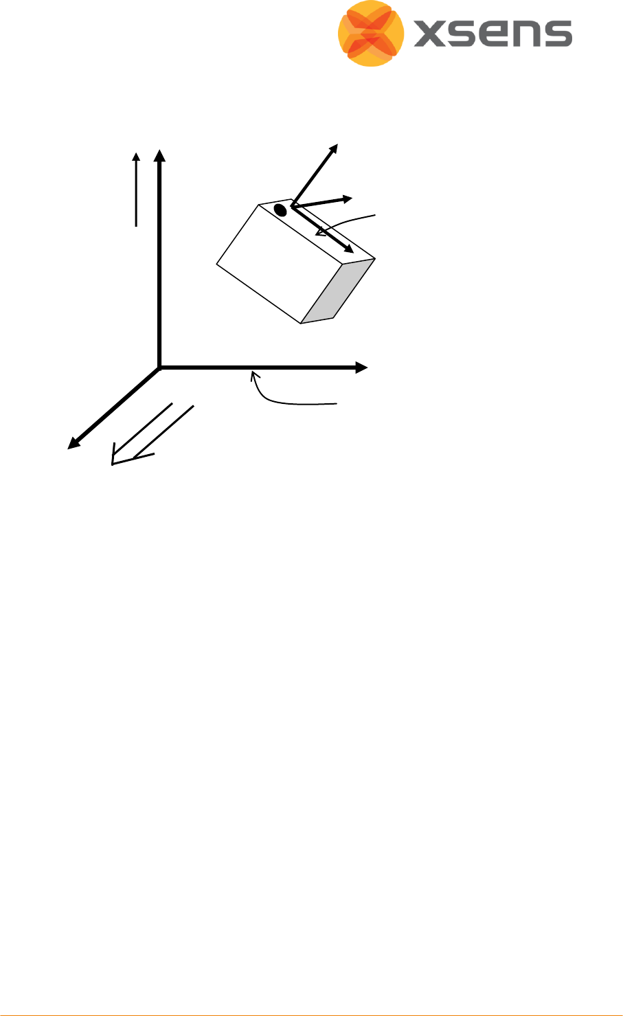
© Xsens Technologies B.V.
62
Please refer to Section 11.7 for further details on output co-ordinate systems and different
options to redefine the output co-ordinate systems.
True North vs. Magnetic North
As defined above the output coordinate system of the MTw is with respect to local Magnetic
North. The deviation between Magnetic North and True North (known as the magnetic
declination) varies depending on your location on earth and can be roughly obtained from
various models of the earth’s magnetic field as a function of latitude and longitude.
11.6.3 Arbitrary Alignment
If the measured kinematics is required in an object coordinate system (O) with a known
orientation with respect to standard sensor coordinate frame (S), the object alignment
matrix can also be set with an arbitrary but known orientation. This is useful if the MTw can
only be fastened in one specific orientation.
The object alignment matrix (ROS) is applied to the output data (RGS) according to the
following equations.
For 3D orientation data:
T
GO GS OS
R R R
For inertial and magnetic data:
OS
R
OS
ss
Example
The object alignment matrix is given by:
Local
Magnetic North
Local
vertical
G
Local tangent plane
Z up, default
X
Z
Y
S
MTw default co-ordinate system
Z up, default
z
x
y
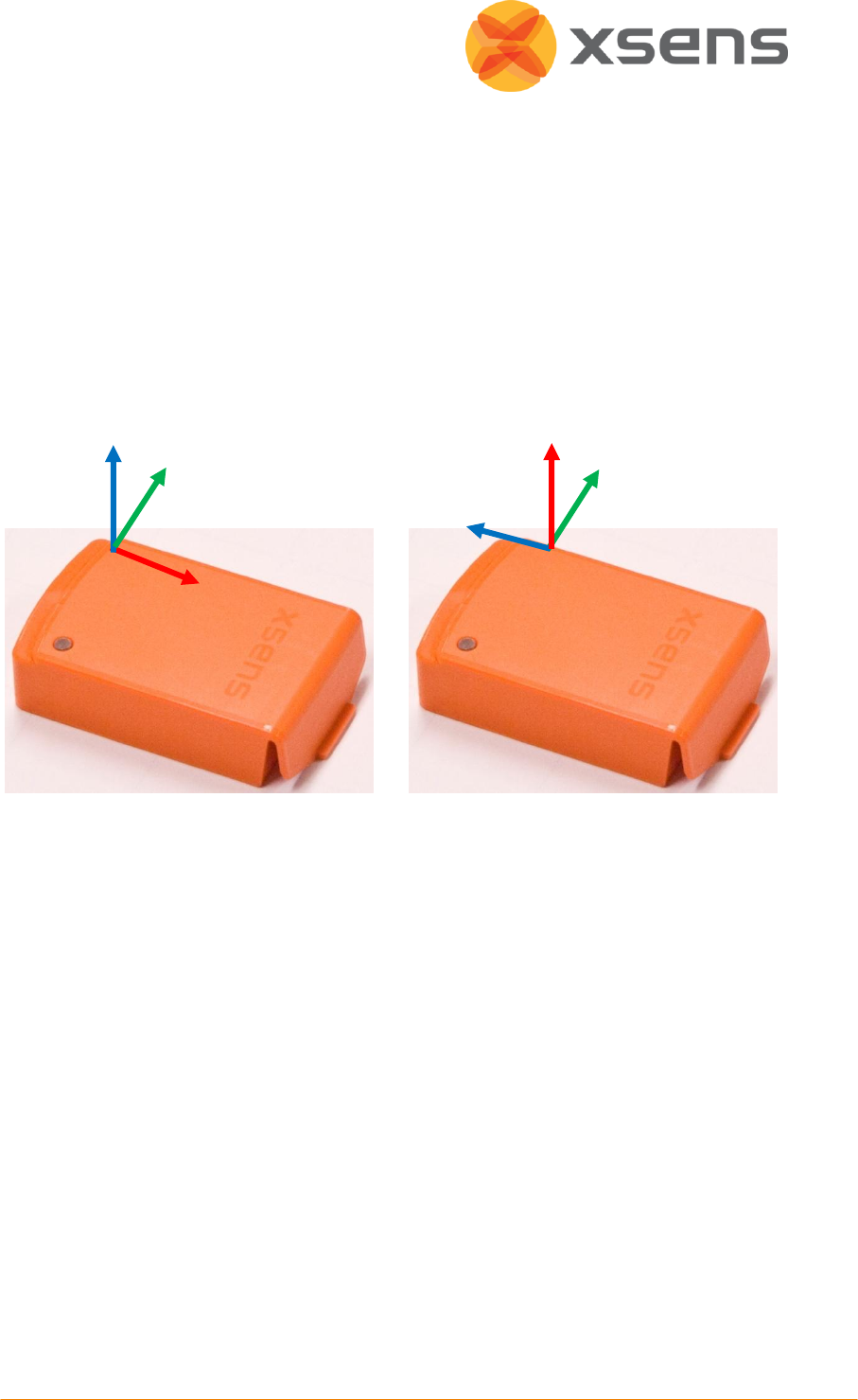
© Xsens Technologies B.V.
63
0 0 1
0 1 0
1 0 0
OS
R
Here O represents the object coordinate system and S the standard sensor coordinate
system described in Section 11.6.2. Once the object alignment matrix is set to ROS, the sensor
output will be expressed with respect to the object coordinate system shown in figure (b),
below.
a
b
11.6.4 Heading Reset
It is often important that the global Z-axis remains along the vertical (defined by local gravity
vector), but the global X-axis has to be in another direction. In this case a heading reset may
be used, this is also known as “bore sighting”. When performing a heading reset, the new
global reference frame is chosen such that the global X-axis points in the direction of the
sensor while keeping the global Z-axis vertical (along gravity, pointing upwards). In other
words: The new global frame has the Z axis along gravity, pointing upwards, the X-axis in the
plane spanned by the vertical and the sensor X-axis, perpendicular to the global Z-axis and
the Y-axis such that a right handed coordinate system is formed.
NOTE: After a heading reset, the yaw may not be exactly zero, this occurs especially when
the X-axis is close to the vertical. This is caused by the definition of the yaw when using Euler
angles, which becomes unstable when the pitch approaches ± 90 deg.
11.6.5 Object Reset
The object reset function aims to facilitate in aligning the MT coordinate frame (S) with the
coordinate frame of the object to which the MT is attached (O). After an object reset, the S
coordinate frame is changed to S’ as follows:
the S’ Z-axis is the vertical (up) at time of reset.
Z
Y
X
Z
X
Y
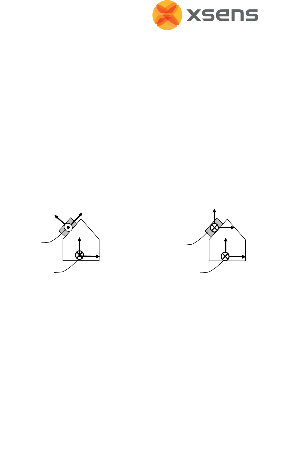
© Xsens Technologies B.V.
64
the S’ X-axis equals the S X-axis, but projected on the new horizontal plane.
the S’ Y-axis is chosen as to obtain a right handed coordinate frame.
NOTE: Once this object reset is conducted, both inertial (and magnetic) and orientation data
will be output in the new coordinate frame (S’).
The object reset can be used to set the MTw coordinate frame to that of the object to which
it is attached (see figure below). The MTw has to be fixated in such a way that the X-axis is in
the XZ-plane of the object coordinate frame (situation A). This means that the MTw can be
used to identify the X-axis of the object. To preserve the global vertical, the object must be
oriented such that the object z-axis is vertical. The object reset causes the new S’ coordinate
frame and the object coordinate frame to be aligned (situation B).
NOTE: Since the sensor X-axis is used to describe the direction of the object X-axis, the reset
will not work if the sensor X-axis is aligned along the Z-axis of the object.
MTw coordinate frame before (A) and after (B) object reset. The new Z-axis of the sensor
coordinate frame will be along the vertical. The new direction of the X-axis will be the old X–
axis that is projected onto the horizontal plane.
11.6.6 Alignment Reset
The alignment reset combines the Object reset and the Heading reset in a single time
instant. This has the advantage that all co-ordinate systems can be aligned with a single
action. Note that the new global reference x-axis (heading) is defined by the object X-axis (to
which XZ-plane of the MTw has been aligned).
NOTE: Once this alignment reset is conducted, both inertial (and magnetic) and orientation
data will be output with respect to the new S’ coordinate frame.
new MTw
coordinate
frame (S’)
Object
coordinat
e frame
(O)
x
x
x
z
B.
A.
MTw
coordinat
e frame
(S)
Object
coordinat
e frame
(O)
y
x
z
z
z
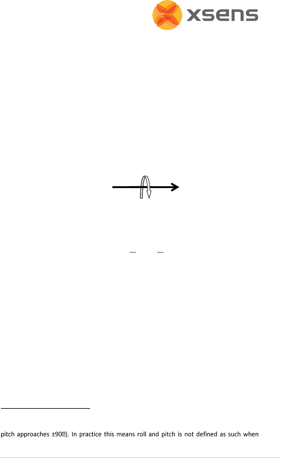
© Xsens Technologies B.V.
65
11.7 Orientation Output Modes
The orientation, calculated by the MTw is the orientation of the sensor-fixed co-ordinate
system (S) with respect to a Cartesian earth-fixed co-ordinate system (G). The output
orientation can be presented in different parameterizations:
Unit Quaternions (also known as Euler parameters)
Euler angles
1
: roll, pitch, yaw (XYZ Earth fixed type, also known as Cardan or aerospace
sequence)
Rotation Matrix (directional cosine matrix)
A positive rotation is always “right-handed”, i.e. defined according to the right hand rule
(corkscrew rule). This means a positive rotation is defined as clockwise in the direction of the
axis of rotation.
11.7.1 Quaternion Orientation Output
A unit quaternion vector can be interpreted to represents a rotation about a unit vector n
through an angle α.
( ( ), ( ))
22
GS
q cos sin
n
A unit quaternion itself has unit magnitude, and can be written in the following vector
format;
qGS = (q0,q1,q2,q3)
|q| = 1
Quaternions are an efficient, non-singular description of 3D orientation and a quaternion is
unique up to sign:
q = -q
An alternative representation of a quaternion is as a vector with a complex part, the real
component is the first one, q0.
1
Please note that due to the definition of Euler angles there is a mathematical singularity
when the sensor-fixed x-axis is pointing up or down in the earth-fixed reference frame (i.e.
pitch is close to ±90 deg. This singularity is in no way present in the quaternion or rotation
matrix output mode.

© Xsens Technologies B.V.
66
The inverse (qSG) is defined by the complex conjugate (†) of qGS. The complex conjugate can
be calculated:
†
0 1 2 3
( , , , )
GS SG
q q q q q q
As defined here qGS rotates a vector in the sensor co-ordinate system (S) to the global
reference co-ordinate system (G).
†
GS GS GS SG
q q q q
G S S
x x x
Hence, qSG rotates a vector in the global reference co-ordinate system (G) to the sensor co-
ordinate system (S), where qSG is the complex conjugate of qGS.
11.7.2 Euler Angles Orientation Output Mode
The definition used for 'Euler-angles' here is equivalent to 'roll, pitch, yaw/heading' (also
known as Cardan). The Euler-angles as orientation output are provided as XYZ Earth fixed
type (subsequent rotation around global X, Y and Z axis, also known as aerospace sequence).
φ = roll
1
= rotation around XG, defined from [-180o…180 o]
θ = pitch
2
= rotation around YG, defined from [-90 o …90 o]
ψ = yaw
3
= rotation around ZG, defined from [-180 o …180 o]
NOTE: Due to the definition of Euler angles there is a mathematical singularity (gimbal lock)
when the sensor-fixed X-axis is pointing up or down in the earth-fixed reference frame (i.e.
pitch approaches ±90o). This singularity is in no way present in the quaternion or rotation
matrix output mode. The singularity cannot be compensated for but only avoided using the
rotation matrix output, then manually extract Euler Angles by using different Euler
sequences
4
.
The Euler-angles can be interpreted in terms of the components of the rotation matrix, RGS,
or in terms of the unit quaternion, qGS;
11
32 2 3 0 1
22
33 0 3
11
31 1 3 0 2
11
1 2 0 3
21
22
11 0 1
22
tan tan 2 2 1
sin ( ) sin (2 2 )
22
tan tan 2 2 1
GS
GS
GS
R q q q q
R q q
R q q q q
q q q q
R
R q q
1
“roll” is also known as: “bank”
2
“pitch” is also known as: “elevation” or “tilt”
3
“yaw” is also known as: “heading”, “pan” or “azimuth”
4
Woltring HJ. 3-D attitude representation of human joints: A standardization proposal.
Journal of Biomechanics. 1994;27 (12):1399-1414.

© Xsens Technologies B.V.
67
Here, the arctangent (tan-1) is the four quadrant inverse tangent function.
NOTE: that the output is in degrees and not radians.
11.7.3 Rotation Matrix Orientation Output Mode
The rotation matrix (also known as Direction Cosine Matrix, DCM) is a well-known,
redundant and complete representation of orientation. The rotation matrix can be
interpreted as the unit-vector components of the sensor coordinate system S expressed in G.
For RGS the unit vectors of S are found in the columns of the matrix, so column 1 is XS
expressed in G etc. A rotation matrix norm is always equal to one (1) and a rotation RGS
followed by the inverse rotation RSG naturally yields the identity matrix I3.
||R|| = 1
RGSRSG = I3
The rotation matrix, RGS, can be interpreted in terms of quaternions;
2 2 2 2
0 1 2 3 1 2 0 3 0 2 1 3
2 2 2 2
0 3 1 2 0 1 2 3 2 3 0 1
2 2 2 2
1 3 0 2 2 3 0 1 0 1 2 3
22
0 1 1 2 0 3 1 3 0 2
22
1 2 0 3 0 2 2 3 0 1
13
2 2 2 2
2 2 2 2
2 2 2 2
2 2 1 2 2 2 2
2 2 2 2 1 2 2
22
GS
q q q q q q q q q q q q
R q q q q q q q q q q q q
q q q q q q q q q q q q
q q q q q q q q q q
q q q q q q q q q q
q q q
22
0 2 2 3 0 1 0 3
2 2 2 2 1q q q q q q q
or in terms of Euler-angles (according to the XYZ Euler sequence);
cos sin 0 cos 0 sin 1 0 0
sin cos 0 0 1 0 0 cos sin
0 0 1 sin 0 cos 0 sin cos
cos cos sin sin cos cos sin cos sin cos sin sin
cos sin sin sin sin cos cos cos sin si
Z Y X
GS
R R R R
n sin cos
sin sin cos cos cos
As defined here RGS, rotates a vector in the sensor co-ordinate system (S) to the global
reference system (G):
()
T
GS SG
RR
G S S
x x x
It follows naturally that, RSG rotates a vector in the global reference co-ordinate system (G)
to the sensor co-ordinate system (S).
For the rotation matrix (DCM) output mode it is defined that:
© Xsens Technologies B.V.
68
11 12 13
21 22 23
31 32 33
GS
a d g R R R
R b e h R R R
c f i R R R
SG
a b c
R d e f
g h i
Here, also the row-order/column-order is defined.
11.8 Synchronisation Examples
11.8.1 Start and stop recording of third party devices using single pulse
Third party device starting and stopping recording of Xsens system, on Line 1 of the Sync In
port.
The output definition in rotation matrix (DCM) output mode is:
MTData DATA =
MID 50 (0x32)
All data elements in DATA field are FLOATS (4 bytes) , unless specified otherwise by
modifying the OutputSetting Data Format field.
ihgfedcba
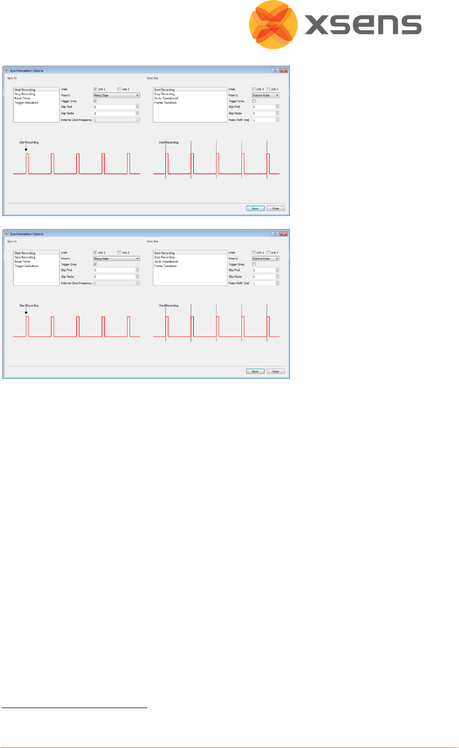
© Xsens Technologies B.V.
69
Select Start Recording
Check the check box for
Line 1
Polarity: Rising Edge1
Trigger Once: Unchecked2
Skip First = 0
Skip Factor = 1 (so that
every other pulse will start
a recording in MT
Manager)
Select Stop Recording
Check the check box for
Line 1
Polarity: Rising Edge
Check the check box for
Trigger Once: Unchecked
Skip First = 1 (first trigger
starts recording, so it
should not also send a
signal to stop - or this
causes confusion for
Awinda Station)
Skip Factor = 1 (so that
every other pulse will stop
a recording in MT
Manager)
The above example indicates how to allow a signal of 3.3V enter the Sync In 1 port, of the
Awinda Station. The first upward going pulse (and subsequent odd numbered pulses),
received on the Awinda Station, will start recording (Polarity = rising edge). The second
upward going pulse (and subsequent even numbered pulses), received on the Awinda
Station, will stop recording.
11.8.2 Start and stop recording of third party devices with infinite pulse width
It is of course also possible, to configure that for example the upward rising edge causes the
start of recording and the negative direction edge causes stop recording, this may be useful
in the event that a third party devices sends a pulse of infinite length.
To do this, the following settings should be input:
1
Note that this setting depends on the signal from third party system.
2
To ensure that a series of recordings can be made.

© Xsens Technologies B.V.
70
Select Start Recording
Check the check box for
Line 1
Polarity: Rising Edge
Trigger Once: Uncheck (if
more than one recording
desired)
Skip first = 0
Skip factor = 0
Select Stop Recording
Check the check box for
Line 1
Polarity: Falling Edge
Trigger Once: Uncheck (if
more than one recording
desired)
Skip first = 0
Skip factor = 0
11.8.3 Start and stop recording of third party devices including trigger indication pulses
In some instances it may be desired to have a trigger indication in the data, for example
using a manual trigger button, or using an external clock. The following example shows how
to do this.
Note: The trigger indication below has been indicated in this example as coming through via
the Sync In 2 channel, while start, stop recording and reset timer come through in the Sync
In 1.if Sync In 1 is also used for the trigger indication, one should additionally insert the
amount of pulses expected between the start and stop recording, therefore changing the
skip factor for stop recording to a large number equivalent to the number of pulses expected
between start and stop recording. If this is known, it can be very efficient, otherwise it may
be limiting. The example shows a simplified method, independent of time needed for
recording or number of trigger pulses expected.
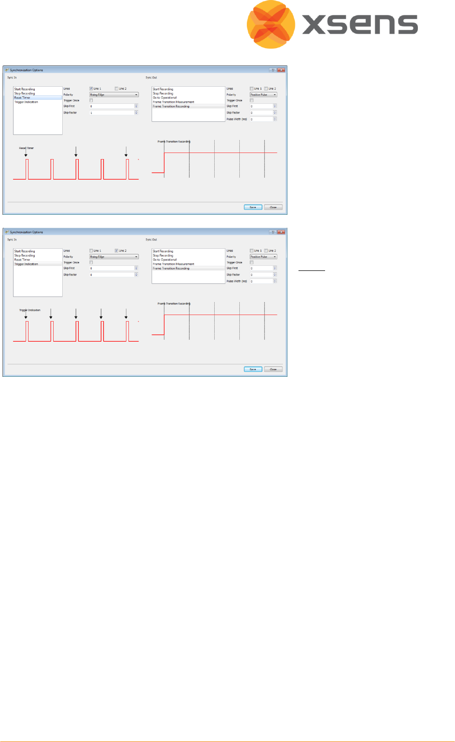
© Xsens Technologies B.V.
71
Use the setting of 11.8.1.
In addition:
Select Reset Timer
Check the check box for
Line 1
Polarity: Rising Edge
Trigger Once: Uncheck
Skip first = 0
Skip factor = 1
Select Trigger Indication
Check the check box for
Line 2
Polarity: Rising Edge
Trigger Once: Uncheck
Skip first = 0
Skip factor = 0
Note:
Stop recording time may not be on the last sample recorded.
Stop recording timestamp is showed in both Trigger In 1 and 2, independent if the trigger
was set on Sync In1 or Sync In 2, this is because the signal comes directly from the Awinda
Station, independent of the line used.
Trigger Indications can be exported to ASCII using the exporter and selecting the Trigger In 1
and / or Trigger In 2 in the preferences menu.
Reset timer resets the timer of the sync events (the amount of milliseconds shown in the
Trigger In events when the data is exported. The exported sample counter, always exported
as the first column will not be reset.
In any synchronisation situation, there should only be one master. It is necessary to elect a
master, either one of the connected Awinda Stations, or a third party device.
11.8.4 Synchronising Two Awinda Stations
Using more than one Awinda Station per MT Manager is possible. While the data received
from each MTw to each Awinda is perfectly time synchronised, the time synchronisation
between the Awinda Stations themselves, running in MT Manager has not been tested. One
way of ensuring good time synchronisation between the Awinda Stations is to use two
separate PCs, connect each Awinda Station to a given PC and synchronise the Awinda
Stations as with a third party device.

© Xsens Technologies B.V.
72
To do this, select which Awinda Station (and MT Manger) will provide the Sync Out signal
(connect the BNC to the correct port) and which will receive the Sync In signal (ensure
correct BNC port connection).
The following settings have been successfully tested in MT Manager to start and stop a
series of recordings using one Awinda Station as the control:
Sync In
Sync Out
Start Recording
Stop Recording
Start Recording
Stop Recording
Rising Edge
Skip First = 0
Skip Factor = 1
Rising Edge
Skip First = 1
Skip Factor = 1
Positive Pulse
Skip First = 0
Skip Factor = 0
Pulse Width = 10ms
Positive Pulse
Skip First = 0
Skip Factor = 0
Pulse Width = 10ms
11.8.5 Synchronising with Noraxon EMG
Synchronisation was successfully tested between MT Manager and Noraxon TeleMyo
system.
The steps described below describe how to make it possible for the Awinda Station to send a
synchronisation signal (Xsens is Sync Out and Noraxon is Sync In) and how to receive the
synchronisation signal (Noraxon is Sync Out, Xsens Sync In).
11.8.5.1 Awinda Station Sends Sync Signal (Noraxon Receives Sync Signal)
Hardware requirements:
Noraxon Hardware
Xsens Hardware
Wireless EMG transmitters
1 TeleMyo DTS (plus antenna)
MTw
Awinda Station
Both systems of course also need related cables to connect to each other (with BNC
connectors at each end) and a USB cable to connect to the PC.
In addition to the normal MTw hardware setup, also connect the BNC connector from the
TeleMyo DTS to Sync Out 1 on the Awinda Station. Connect the USB connection between the
TeleMyo DTS and the PC. When switched on, the DTS will display “USB ready”.
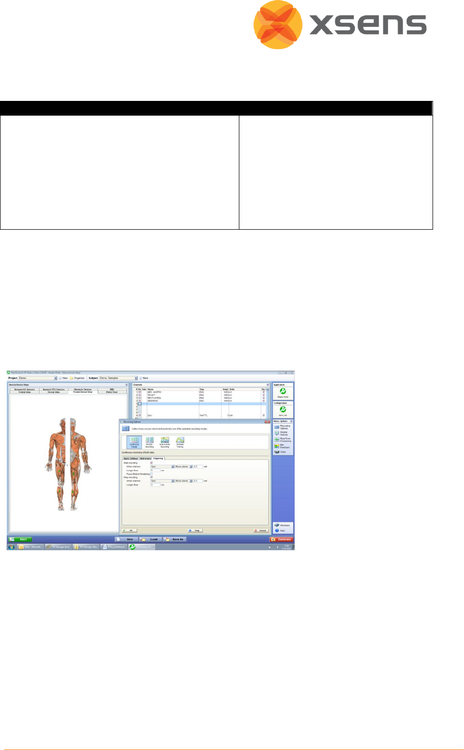
© Xsens Technologies B.V.
73
11.8.5.2 Software Setup in MT Manager
Synchronisation on Sync Out Line 1:
Sync Out
Select Start Recording
Check the check box for Line 1
Polarity: Rising Edge
Trigger Once: Uncheck
Skip first = 0
Skip factor = 0
Pulse width = 10 ms
Select Stop Recording
Check the check box for Line 1
Polarity: Rising Edge
Trigger Once: Uncheck
Skip First = 0
Skip Factor = 0
Pulse width = 10 ms
Set up the wireless configuration in MT Manager.
11.8.5.3 Software Setup Noraxon MyoResearch Software:
The example given below is for is gait analysis, measuring the medial gastrocnemius, tibialis
anterior, semitendinosus and the rectus femoris. For an 8-Channel EMG system, Channel 9 is
selected as the synchronisation line in the Noraxon MyoResearch Software. If a 16 channel
system is in use, this is the 17th channel.
Return to the main menu,
under >Measuring
Options, go to >Recording
Options, then >Triggering
tab.
Check the check box beside “Start Recording”;
Go to the drop down menu beside “When Channel”, select “Sync”;
Select Rises Above (ensure that this is also the direction indicated on the mini-
receiver);
Input e.g. 0.5V
Longer than 5ms
Repeat settings for Stop Recording.
Navigate further through the software.
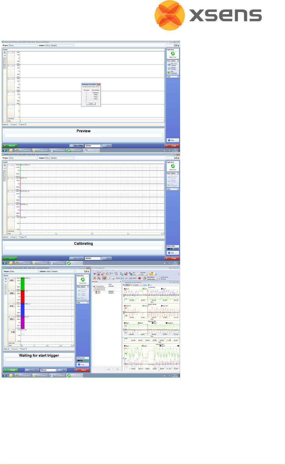
© Xsens Technologies B.V.
74
The Noraxon software
initialises the EMG signals.
When this screen is
reached, click record, on
the bottom left hand side
of the screen on the
Noraxon software.
The software indicates
that it is waiting for the
trigger.
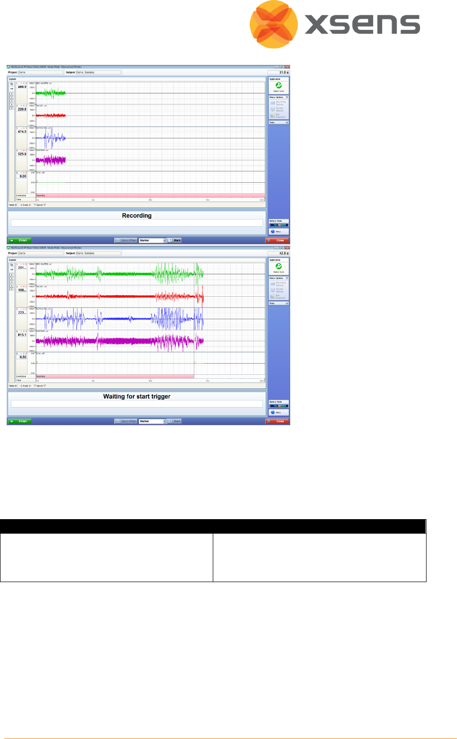
© Xsens Technologies B.V.
75
Press Record in MT
Manager, the button is
depressed and the
Noraxon software
indicates that recording
has started.
Repressing record in MT
Manager will stop the
recording on both
systems, where Noraxon
will again indicate waiting
for start trigger.
11.8.5.4 Awinda Station Receives Sync Signal (Noraxon Sends Sync Signal)
For the Xsens system to send the synchronisation commands, the mini-receiver from
Noraxon is not needed.
Hardware requirements:
Noraxon Hardware
Xsens Hardware
Wireless EMG transmitters
1 TeleMyo DTS (plus antenna)
1 TeleMyo mini-receiver (plus antenna)
MTw
Awinda Station
Both systems of course also need related cables to connect to each other (with BNC
connectors at each end) and a USB cable to connect to the PC.
In addition to the normal MTw hardware setup, set up the hardware of the Noraxon system
as follows:
USB port of TeleMyo mini-receiver to USB of PC.
Connect jack connector to Sync Out port of TeleMyo mini-receiver to BNC connection Sync In
1 of Awinda Station.

© Xsens Technologies B.V.
76
Manual trigger pulse, jack connector to Sync In port of TeleMyo minirecevier.
Connect the external antenna to the TeleMyo DTS.
When successfully connected and switched on, the TeleMyo DTS will display “WiFi ready”.
11.8.5.5 Software Setup: MT Manager
Synchronisation on the Sync In Line 1 port:
Sync In
Select Start Recording
Check the check box for Line 1
Polarity: Rising Edge
Trigger Once: Uncheck
Skip first = 0
Skip factor = 1
Select Stop Recording
Check the check box for Line 1
Polarity: Rising Edge
Trigger Once: Uncheck
Skip First = 1
Skip Factor = 1
Set up the wireless configuration in MT Manager.
To initialise recording, click the Record button. To indicate that MT Manager is waiting for an
external pulse, the icon changes from the normal red dot to one with the pause symbol
overlaid, as shown in Section 6.7.2.
11.8.5.6 Software Setup: Noraxon MyoResearch Software:
Based on the output settings described for MT Manager, the settings for Noraxon
MyoResearch software can remain the same. The difference is that instead of the trigger
pulse coming from the record button in MT Manager, this now comes from the manual
button connected to the mini-receiver. Additionally, the mini-receiver should be set up as
follows:
Go to the hardware menu;
Select the TeleMyo mini-receiver from the list of icons;
Select: settings;
Select: Configure;
Ensure that the wireless sync is “External Pulse” and Input Range is ±5V