Xsens Technologies AW-A2 Wireless Awinda Station User Manual
Xsens Technologies B.V. Wireless Awinda Station Users Manual
Users Manual

Document MV0319P, Revision N, June 2015
User Guide MVN, MVN BIOMECH
MVN Link, MVN Awinda
MVN User Manual

Document MV0319P.N
© Xsens Technologies B.V.
MVN User Manual
ii
Revisions
Revision
Date
By
Changes
N
June 2015
HBE
Changes made to accommodate MVN Studio 4.2
9.3 Add comments after recording
15.3 Software Activation Tool: Offline License Activation or
Updating a License
15.4 Software Activation Tool: Applying an Update
15.5 RUS Utility: Rehosting a Sentinel protection key
© 2015, Xsens. All rights reserved. Information in this document is subject to change without notice.
Xsens, MVN, MotionGrid, MTi, MTi-G, MTx, MTw, Awinda and KiC are registered trademarks or
trademarks of Xsens Technologies B.V. and/or its parent, subsidiaries and/or affiliates in The
Netherlands, the USA and/or other countries. All other trademarks are the property of their respective
owners.

Document MV0319P.N
© Xsens Technologies B.V.
MVN User Manual
iii
Table of Contents
REVISIONS ................................................................................................................................................. II
TABLE OF CONTENTS ................................................................................................................................. III
ABBREVIATIONS AND TERMS .................................................................................................................... IX
DEFAULT FOLDERS ..................................................................................................................................... X
1 INTRODUCTION ................................................................................................................................ 1
2 CONTENT OVERVIEW ........................................................................................................................ 2
2.1 MVN LINK SUITCASE WITH CONTENTS ..................................................................................................... 2
2.2 MOTION TRACKER (MTX) .................................................................................................................... 2
2.3 BODY PACK (BP), BATTERY PACK, AND ACCESS POINT (AP) ........................................................................... 3
2.4 CABLING ......................................................................................................................................... 3
2.5 MVN AWINDA BACKPACK/SUITCASE WITH CONTENTS .................................................................................. 4
2.6 MOTION TRACKER (MTW) ................................................................................................................... 4
2.7 AWINDA STATION .............................................................................................................................. 4
2.8 MVN AWINDA CHARGER .................................................................................................................... 5
2.9 “THE SUIT” ..................................................................................................................................... 5
2.10 MOTION TRACKERS ON THE EXTREMITIES .................................................................................................. 6
2.11 MVN ETHERNET CAMERA .................................................................................................................... 6
2.12 SOFTWARE ...................................................................................................................................... 6
3 GETTING STARTED ............................................................................................................................ 7
3.1 INSTALLATION OF SOFTWARE ................................................................................................................. 7
3.2 SETUP HARDWARE ............................................................................................................................. 7
3.3 MVN STUDIO WORKFLOW OVERVIEW ..................................................................................................... 7
3.4 TIPS FOR BEST PRACTICE....................................................................................................................... 8
3.4.1 Operating conditions ............................................................................................................ 8
3.4.2 Absolute maximum ratings .................................................................................................... 9
3.4.3 Suit, shirt, short maintenance .............................................................................................. 10
3.4.4 FabriFoam Velcro Straps ..................................................................................................... 10
3.4.5 Dynamic movements .......................................................................................................... 10
3.4.6 Finding a magnetic “sweet spot” ......................................................................................... 10
3.4.7 Warming up the filters ........................................................................................................ 10
3.4.8 CH5000 Charger Safety ....................................................................................................... 10
4 SOFTWARE ..................................................................................................................................... 11
4.1 SOFTWARE INSTALLATION .................................................................................................................. 11
4.2 SOFTWARE ACTIVATION..................................................................................................................... 11
4.2.1 Software License Key .......................................................................................................... 11
4.2.2 Dongle License Key ............................................................................................................. 11
4.2.3 Network License Key ........................................................................................................... 12
5 HARDWARE .................................................................................................................................... 13
5.1 MVN LINK .................................................................................................................................... 13
5.2 MOTION TRACKERS (MTX) ................................................................................................................. 13
5.3 BODY PACK (BP) AND BATTERY ........................................................................................................... 14

Document MV0319P.N
© Xsens Technologies B.V.
MVN User Manual
iv
5.4 SYNC STATION ................................................................................................................................ 14
5.5 BATTERY CHARGER .......................................................................................................................... 15
5.5.1 Using your Charger ............................................................................................................. 15
5.5.2 Charging ............................................................................................................................ 15
5.5.3 Fuel Gauge Recalibration .................................................................................................... 15
5.5.4 What is fuel gauge recalibration and why is it needed? ......................................................... 16
5.5.5 BP Power on/off and status LED ........................................................................................... 17
5.5.6 BP Status LED ..................................................................................................................... 17
5.5.7 Setup for wired connection via Ethernet ............................................................................... 17
5.5.8 Running a Wi-Fi Protected Setup (WPS) ................................................................................ 17
5.6 ACCESS POINT (AP) ......................................................................................................................... 18
5.6.1 Positioning the Access Point ................................................................................................ 19
5.7 MVN (BIOMECH) AWINDA .............................................................................................................. 20
5.7.1 Wireless Motion Trackers (MTw) ......................................................................................... 20
5.7.2 MTw LED Indications .......................................................................................................... 21
5.7.3 MTw Stand-by Mode .......................................................................................................... 21
5.7.4 Exiting stand-by mode ........................................................................................................ 21
5.7.5 Awinda Station ................................................................................................................... 22
5.7.6 Awinda Station Synchronization Ports .................................................................................. 22
5.7.7 Awinda Station Status LED .................................................................................................. 23
5.7.8 Awinda USB Dongle ............................................................................................................ 24
5.7.9 Awinda USB Dongle LED ...................................................................................................... 24
5.7.10 Powering off MVN Awinda .................................................................................................. 24
5.8 MVN (ETHERNET) CAMERA ............................................................................................................... 24
5.9 THE SUIT ....................................................................................................................................... 24
5.9.1 Straps ................................................................................................................................ 24
5.9.2 MVN Lycra suit ................................................................................................................... 26
5.9.3 Putting on the remaining Motion Trackers ............................................................................ 27
5.9.4 Foot pads ........................................................................................................................... 27
5.9.5 Putting on the Body Pack and Battery Pack ........................................................................... 27
5.9.6 Tracker locations ................................................................................................................ 27
5.10 CONNECTING THE HARDWARE AND SOFTWARE ......................................................................................... 28
6 MVN STUDIO .................................................................................................................................. 29
6.1 STATUS BAR ................................................................................................................................... 30
7 WORKFLOW AND FUNCTIONALITIES IN MVN STUDIO ....................................................................... 31
7.1 NEW SESSION ................................................................................................................................. 31
7.1.1 Create a New Recording Session .......................................................................................... 31
7.1.2 New Session, step-wise ....................................................................................................... 31
7.2 CONFIGURE AN MVN SYSTEM ............................................................................................................. 32
7.2.1 Enable/disable search for new system .................................................................................. 32
7.2.2 System Status ..................................................................................................................... 32
7.2.3 Apply Changes.................................................................................................................... 32
7.2.4 Configured Item ................................................................................................................. 32
7.2.5 Suit Color ........................................................................................................................... 32
7.2.6 System Name ..................................................................................................................... 32
7.2.7 Expanding and Collapsing Views .......................................................................................... 33
7.2.8 View Hardware Status ........................................................................................................ 33
7.2.9 Update Rate ....................................................................................................................... 33

Document MV0319P.N
© Xsens Technologies B.V.
MVN User Manual
v
7.2.10 System Status ..................................................................................................................... 33
7.2.11 Suit Configuration ............................................................................................................... 33
7.2.12 Scenario ............................................................................................................................. 34
7.2.13 Accept Systems .................................................................................................................. 34
7.2.14 Sync Settings ...................................................................................................................... 34
7.3 CONFIGURING THE VIDEO CAMERA ....................................................................................................... 34
7.3.1 Configuration ..................................................................................................................... 34
7.4 DEFINE X-AXIS ............................................................................................................................... 35
7.5 CONFIGURING THE SYNC STATION......................................................................................................... 36
7.6 CONFIGURATION GROUP ................................................................................................................... 36
7.7 LOADING CONFIGURATIONS USING THE LIBRARY BUTTON ............................................................................. 36
7.8 HARDWARE STATUS ......................................................................................................................... 37
7.8.1 Relocating motion trackers .................................................................................................. 38
7.8.2 MVN Awinda: Changing Radio Channel ................................................................................ 38
7.8.3 MVN Awinda: Changing Radio Channel ................................................................................ 39
7.8.4 MVN Awinda: Reject Unused Trackers .................................................................................. 39
7.8.5 MVN Awinda: Forget System ............................................................................................... 39
7.9 PROPS .......................................................................................................................................... 39
7.10 NAVIGATOR ................................................................................................................................... 41
8 SETUP ............................................................................................................................................. 42
8.1 BODY DIMENSIONS .......................................................................................................................... 42
8.1.1 Offline Body Dimensions ..................................................................................................... 44
8.2 CALIBRATION ................................................................................................................................. 46
8.2.1 Calibration steps ................................................................................................................ 46
8.2.2 N-Pose (Neutral pose) ......................................................................................................... 47
8.2.3 T-pose ............................................................................................................................... 47
8.2.4 Expert Calibration: Hand Touch ........................................................................................... 48
8.2.5 Hands-off calibration .......................................................................................................... 48
8.2.6 Calibration quality .............................................................................................................. 48
9 PREVIEW AND RECORDING .............................................................................................................. 50
9.1 PREVIEW ....................................................................................................................................... 50
9.1.1 Viewport Icons ................................................................................................................... 51
9.1.2 Views ................................................................................................................................ 52
9.1.3 Overcoming distortions ....................................................................................................... 52
9.1.4 Real-time graphs ................................................................................................................ 53
9.1.5 Save and Restore Layout ..................................................................................................... 54
9.2 RECORDING ................................................................................................................................... 54
9.2.1 Note for recording for MVN Awinda Users ............................................................................ 54
9.3 ADD COMMENTS AFTER RECORDING ...................................................................................................... 55
9.4 RECOVERY OF MVN FILE AFTER SYSTEM CRASH ......................................................................................... 55
9.5 MARKERS ...................................................................................................................................... 56
9.6 NETWORK STREAMER ....................................................................................................................... 57
9.7 NETWORK MONITOR ........................................................................................................................ 59
10 PLAYBACK AND EDITING ................................................................................................................. 60
10.1 PLAYBACK ..................................................................................................................................... 60
10.2 SYNCHRONIZATION WITH VIDEO ........................................................................................................... 60
10.3 CONTACT POINT EDITING ................................................................................................................... 61

Document MV0319P.N
© Xsens Technologies B.V.
MVN User Manual
vi
10.3.1 Selection of samples ........................................................................................................... 63
10.3.2 Contact point editing options .............................................................................................. 64
10.4 REPROCESSING ............................................................................................................................... 66
10.5 MULTI-PERSON EDITING .................................................................................................................... 67
11 DATA ANALYSIS .............................................................................................................................. 68
11.1 GRAPHS ........................................................................................................................................ 68
11.1.1 Parameter vs. Time ............................................................................................................. 68
11.1.2 Coordination / Phase Plots (Parameter vs. Parameter) .......................................................... 68
11.1.3 Graph handling .................................................................................................................. 69
11.1.4 Graph toolbar .................................................................................................................... 69
11.1.5 Scaling Options .................................................................................................................. 69
11.1.6 Zoom ................................................................................................................................. 69
11.1.7 Pan ................................................................................................................................... 70
11.1.8 Show/ Hide Legends ........................................................................................................... 70
11.1.9 Show Numerical Values on Graphs ....................................................................................... 70
11.1.10 Equal axes.......................................................................................................................... 70
11.1.11 Amount and layout of graphs .............................................................................................. 70
11.2 CASCADE / TILE WINDOWS ................................................................................................................. 71
11.3 LINKED VIEWS ................................................................................................................................. 71
12 SAVING AND EXPORTING ................................................................................................................ 72
12.1 APPLYING (SMOOTHING) FILTERS TO EXPORTED DATA ................................................................................ 72
12.1.1 Exporter smoothing ............................................................................................................ 72
12.1.2 Output filtering: LXsolver .................................................................................................... 73
12.2 BVH ........................................................................................................................................... 73
12.2.1 Frame skip ......................................................................................................................... 75
12.2.2 Overwrite first frame with T-pose ........................................................................................ 75
12.2.3 Output Presets ................................................................................................................... 75
12.2.4 Output Unit ........................................................................................................................ 75
12.3 C3D ............................................................................................................................................ 76
12.3.1 Points exported in C3D Exporter ........................................................................................... 77
12.4 FBX ............................................................................................................................................ 78
12.5 MVNX ........................................................................................................................................ 79
12.5.1 Importing MVNX files into Excel and MATLAB ....................................................................... 84
12.6 EXPORT MOVIE ............................................................................................................................... 85
13 FEATURES OF MVN STUDIO ............................................................................................................. 86
13.1 PLUG-INS ...................................................................................................................................... 87
14 MVN ETHERNET CAMERA ................................................................................................................ 88
14.1 USING THE MVN CAMERA GS650 ....................................................................................................... 88
14.2 CAMERA DRIVER .............................................................................................................................. 89
14.3 NETWORK CONFIGURATION ................................................................................................................ 89
14.4 JUMBO FRAMES .............................................................................................................................. 89
14.5 CAMERA USAGE GUIDELINES .............................................................................................................. 90
15 XSENS PERIPHERAL SOFTWARE........................................................................................................ 91
15.1 MAGNETIC FIELD MAPPER (MFM) ....................................................................................................... 91
15.2 FIRMWARE UPDATER ........................................................................................................................ 91

Document MV0319P.N
© Xsens Technologies B.V.
MVN User Manual
vii
15.3 SOFTWARE ACTIVATION TOOL: OFFLINE LICENSE ACTIVATION OR UPDATING A LICENSE ........................................ 91
15.3.1 Step 1: Retrieve the license information from a Sentinel protection key ................................... 91
15.3.2 Step 2: Send the C2V file ...................................................................................................... 91
15.3.3 Step 3: Apply the received v2c file using the Software Activation tool. ..................................... 91
15.4 SOFTWARE ACTIVATION TOOL: APPLYING AN UPDATE ................................................................................ 92
15.5 RUS UTILITY: REHOSTING A SENTINEL PROTECTION KEY............................................................................... 92
15.5.1 Step 1: Collect Information about the Recipient Computer ..................................................... 92
15.5.2 Step 2: Generate the License Transfer File ............................................................................. 92
15.5.3 Step 3: Apply the License Transfer File .................................................................................. 92
16 TROUBLESHOOT ............................................................................................................................. 93
17 WARRANTY AND LIABILITY .............................................................................................................. 97
17.1 CUSTOMER SUPPORT ........................................................................................................................ 97
18 REGULATORY NOTICES MVN AWINDA ............................................................................................. 98
18.1 RADIO FREQUENCY EXPOSURE AND EMISSION .......................................................................................... 98
18.2 FCC STATEMENTS............................................................................................................................ 98
18.3 DECLARATION OF CONFORMITY ......................................................................................................... 100
18.3.1 CE Declaration of Conformity MTw2, Awinda Station, Awinda Dongle .................................. 100
18.3.2 FCC Declaration of Conformity MTw2 ................................................................................. 101
18.3.3 FCC Declaration of Conformity Awinda Station .................................................................... 102
18.3.4 FCC Declaration of Conformity Awinda Dongle .................................................................... 103
19 APPENDICES ................................................................................................................................. 104
19.1 LYCRA SUIT SIZES OVERVIEW .............................................................................................................. 104
19.2 MAGNETIC DISTURBANCES ............................................................................................................... 104
19.2.1 Show magnetic disturbance............................................................................................... 104
19.2.2 Magnetic Norm ................................................................................................................ 105
19.3 MVN KINEMATICS AND OUTPUT ........................................................................................................ 107
19.3.1 Quaternion orientation representation ............................................................................... 107
19.3.2 Conversions...................................................................................................................... 107
19.4 BODY PLANES ............................................................................................................................... 108
19.5 COORDINATE SYSTEMS .................................................................................................................... 108
19.6 ANATOMICAL MODEL ...................................................................................................................... 110
19.6.1 Definition of segment axes ................................................................................................ 110
19.6.2 Bony/anatomical landmarks.............................................................................................. 111
19.7 SEGMENT AXES DEFINITIONS AND ORIGIN DEFINITIONS ............................................................................. 114
19.7.1 Spinal segments: L5, L3, T12, T8: Segments 2-5 ................................................................... 114
19.7.2 Neck: Segment 6............................................................................................................... 115
19.7.3 Head: Segment 7 .............................................................................................................. 115
19.7.4 Shoulder: Segment 8 Right and Segment 12 Left ................................................................. 115
19.7.5 Upper Arm (Humerus): Segment 9 Right and Segment 13 Left .............................................. 116
19.7.6 Forearm (Radius/Ulna): Segment 10 Right and Segment 14 Left ........................................... 116
19.7.7 Hand: Segment 11 Right and Segment 15 Left .................................................................... 117
19.7.8 Upper Leg (Femur): Segment 16 Right and Segment 20 Left ................................................. 117
19.7.9 Lower Leg (Tibia/Fibula): Segment 17 Right and Segment 21 Left ......................................... 118
19.7.10 Foot (Calcaneus): Segment 18 Right and Segment 22 Left .................................................... 119
19.7.11 Toe: Segment 19 Right and Segment 23 Left ....................................................................... 119
19.8 JOINT ANGLES ............................................................................................................................... 119

Document MV0319P.N
© Xsens Technologies B.V.
MVN User Manual
viii
19.8.1 Euler Extractions for the joint angles .................................................................................. 120
19.8.2 Shoulder angle definitions ................................................................................................. 120
19.8.3 Joint angle outputs ........................................................................................................... 121
19.9 XKF-HM .................................................................................................................................... 122
19.9.1 Height tracking ................................................................................................................ 122
19.9.2 XKF-HM Settling time ........................................................................................................ 122
19.10 UPDATE RATE VERSUS SAMPLE FREQUENCY ........................................................................................... 123
19.11 STRAP DOWN INTEGRATION ............................................................................................................. 123
19.12 THE AWINDA PROTOCOL ................................................................................................................. 123
19.12.1 Choosing a Radio Channel for MVN Awinda ........................................................................ 124
19.13 SYSTEM SPECIFICATIONS .................................................................................................................. 125
20 CONTACT POINT EDITING EXAMPLES ............................................................................................. 129
20.1.1 Example 1 ........................................................................................................................ 129
20.1.2 Example 2 ........................................................................................................................ 130
21 WORKING WITH DIFFERENT APPLICATIONS .................................................................................... 131
21.1.1 Autodesk 3ds Max ............................................................................................................ 131
21.1.2 Autodesk MotionBuilder.................................................................................................... 131
21.2 MOTIONBUILDER WORKFLOW ........................................................................................................... 132
22 IMPORTING MVNX FILES TO OTHER PROGRAMS ............................................................................ 134
22.1.1 Import to Microsoft Excel .................................................................................................. 134
22.1.2 Import to MATLAB ............................................................................................................ 139
23 SYNCHRONIZATION WITH THIRD PARTY DEVICES ........................................................................... 140
23.1 THE HARDWARE ............................................................................................................................ 140
23.1.1 Important note when receiving 5V synchronization pulses ................................................... 140
23.2 SYNC IN ...................................................................................................................................... 141
23.3 SYNC OUT ................................................................................................................................... 142
23.3.1 Settings in MVN Studio ..................................................................................................... 143
23.4 IMPORTANT NOTICES FOR SYNC IN ...................................................................................................... 143
23.4.1 Sync In Recommended Settings .......................................................................................... 144
23.5 SYNC IN WITH MVN STUDIO ............................................................................................................ 144
23.6 SYNC OUT WITH MVN STUDIO .......................................................................................................... 144
23.7 SYNCHRONIZATION EXAMPLES ........................................................................................................... 145
23.7.1 Start and stop recording of third party devices using single pulse ......................................... 145
23.7.2 Start and Stop Recording Third Party Devices with Infinite Pulse Width ................................. 145
23.7.3 Synchronizing with Noraxon EMG ...................................................................................... 146
23.8 MORE SYNCHRONIZATION EXAMPLES .................................................................................................. 151
24 REFERENCES ................................................................................................................................. 152

Document MV0319P.N
© Xsens Technologies B.V.
MVN User Manual
ix
Abbreviations and Terms
API
Application Programming Interface
AP
Access Point: The method of transporting data from the body pack to the PC
BP
Body Pack, on-body controller unit for the motion trackers, connects to power and
wireless transmission of data to host PC via the Access Point
.BVH
Biovision Hierarchy character animation file format
.C3D
Coordinate 3D export format
Character
Subject in 3D view
.FBX
Filmbox animation file format
IK
Inverse kinematics
MTx
Xsens Inertial and Magnetic Measurement Unit with on-body cables
MTx-STR
String of Xsens Inertial and Magnetic Measurement Units
MTw
Xsens completely wireless Inertial and Magnetic Measurement Unit
MT
Xsens Inertial and Magnetic Measurement Unit (generic reference to MTw or MTx)
MVN
MVN native file format
MVN camera
(Ethernet camera)
Physical camera packaged with MVN Studio Pro for video reference data
MVN Straps
Velcro straps for attaching MTw to the body
MVN Suit
Lycra suit
MVN system
Complete MVN product (hardware and software)
.MVNA
MVN subject dimensions file
.MVNS
MVN session file
.MVNX
MVN open XML file format
SDK
Software Development Kit
Sensor
Components of the MTx, e.g. gyroscope, accelerometer
Subject
Person in the suit
The suit
MVN Straps and Lycra suit - whichever applies
Motion Tracker
MTw, MTx or MTx-STR
UDP
User Datagram Protocol (for data streaming over Local Area Network (LAN))
XKF
Xsens signal processing methods

Document MV0319P.N
© Xsens Technologies B.V.
MVN User Manual
x
Default Folders
Description
Files
Location
Main program
MVN Studio.exe
C:\Program Files\Xsens\MVN Studio
<version>\MVN Studio
Documentation
MVN Quick Setup
Sheet.pdf
C:\Program Files\Xsens\MVN Studio
<version>\Documentation

Document MV0319P.N
© Xsens Technologies B.V.
MVN User Manual
1
1 Introduction
The Xsens MVN inertial motion capture system is an easy to use, cost efficient system for full-body
human motion capture. MVN is based on Xsens' state-of-the-art miniature inertial sensors and wireless
communication solutions combined with advanced sensor fusion algorithms, using assumptions of
biomechanical models.
MVN is a completely portable system; it is not restricted to a studio or lab. It can be used anywhere:
outside, in the office, and on the work floor. There are no limitations in measurement volume (except
the wireless range).
This MVN system is a full body inertial kinematic measurement system, incorporating synchronized
video data. Instant graphical output is provided, including joint angles. An additional C3D exporter has
been implemented, as well as improved MVNX (XML) output, containing all of the segment information
included in the Xsens MVN system as well as joint angle data, center of mass and factory calibrated
sensor data.
Examples of fields of use:
Biomechanics, sport, rehabilitation, ergonomics and human-machine interaction.
Benefit from the fully ambulant measurement system, advanced functional axes calibration, no need
to palpate bony landmarks for marker placement, direct low-noise measurement of acceleration and
angular velocity enabling easier internal forces/momentum calculations.
3D Animation.
Enjoy unprecedented ease-of-use, rich and smooth data, very short setup time, and the absence of
cumbersome post-processing of markers or lost data.
Virtual reality, training & simulation.
Benefit from the highly portable system and a price-point enabling full-body insertion of (multiple)
subjects in VR for highest degree of immersion, low-latency smooth motion data.
Document MV0319P.N
© Xsens Technologies B.V.
MVN User Manual
2
2 Content overview
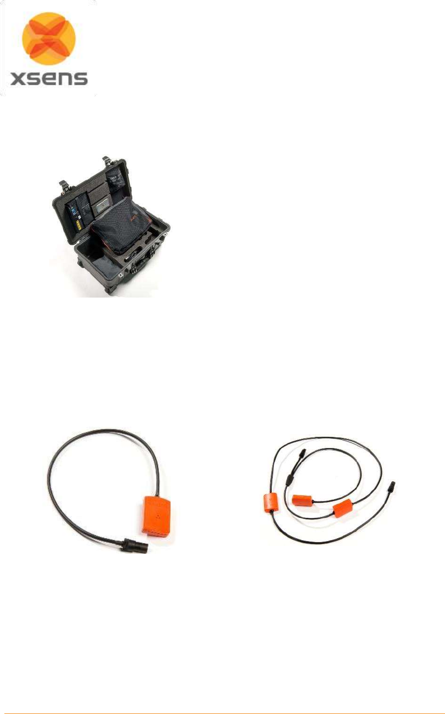
2.1 MVN Link suitcase with contents
Figure 1: Suitcase containing the MVN Link
System
The MVN Link System arrives in a strong, durable
and watertight case. The case has wheels and an
extendable handle for easy transportation. The
suitcase dimensions meet the requirements for
most airline hand-luggage. The suitcase contains:
4 MTx String with three trackers
6 Motion Trackers (MTx)
1 Body Pack
1 Battery Pack
1 Battery charger
1 Access Point
1 Upper Body Cable
1 Lower Body Cable
1 Battery Cable
1 Y Cable
Lycra suit including headband, gloves, shorts,
footpads
Straps for additional securing of trackers
1 Segmometer
Quick set-up sheet
2.2 Motion Tracker (MTx)
Figure 2: Motion Tracker (MTx)
Figure 3: Motion Tracker (MTx-STR)
The MVN Link system contains two types of motion trackers; the single MTx (Figure 2) used as end
trackers and the string of three MTx-STR (Figure 3). The motion trackers, MTx, and MTx-STR are the
miniature inertial measurement units containing 3D linear accelerometers, 3D rate gyroscopes, 3D
magnetometers, and a barometer, which measures atmospheric pressure. These trackers are placed at
strategic locations on the body (fixed by the suit), to measure the motions of each body segment.
The MTx trackers are positioned on the pelvis, sternum, hands, and head. The MTx-STR’s are used to
chain the legs (upper leg, lower leg, and feet), as well as for the upper body (shoulders, upper arms,
and for-arms). For more information about Motion Trackers, see Section 5.2.
Document MV0319P.N
© Xsens Technologies B.V.
MVN User Manual
3
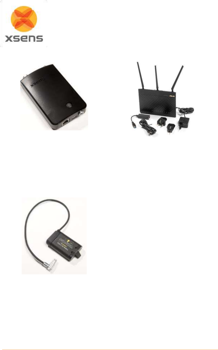
2.3 Body Pack (BP), Battery Pack, and Access Point (AP)
Figure 4: Body Pack (BP)
Figure 4 shows the Body Pack (BP). The strings
of MTx’s are interconnected by the Body Pack. It
delivers power from the battery pack to the
connected MTx’s and retrieves their data
ensuring exactly synchronized samples.
For more information about the Body Pack, see
Section 5.3.
Figure 5: Access Point (AP)
Figure 5 shows the Access Point. The Access
Point pairs with the Body Pack to handle the data
traffic between the BP and the computer. This
Access Point connects to the PC or laptop via
Ethernet cable or wirelessly and is powered using
a proprietary power adapter or laptop battery.
One Access Point can connect to multiple MVN
systems. For more information about the Access
Point, see Section 5.6.
Figure 6 Battery Pack (Battery)
Figure 6 shows the Battery Pack, which connects
to the Body Pack via the Battery Cable. The
Battery Pack is a single unit made up of 3 Lithium
Ion rechargeable cells, and has a typical rating of
10.8V and 2.9Ah. This Battery charges via a
single bay standard smart charger and provides
up to 9.5 hours of continuous recording time to
the system.
2.4 Cabling
While transmission from the subject to the PC is completely wireless, there are a number of cables
running through the MVN Link suit, connecting the MTx and MTx-STR’s to the Body Pack. Additionally,
if the user chooses, there is the option of transmitting motion data to the PC from the BP by directly
using an Ethernet cable between the Body Pack and the Access Point. This is particularly useful for
applications such as skiing or snowboarding, where the wearer of the suit can connect directly to a
laptop carried in a backpack.
Document MV0319P.N
© Xsens Technologies B.V.
MVN User Manual
4
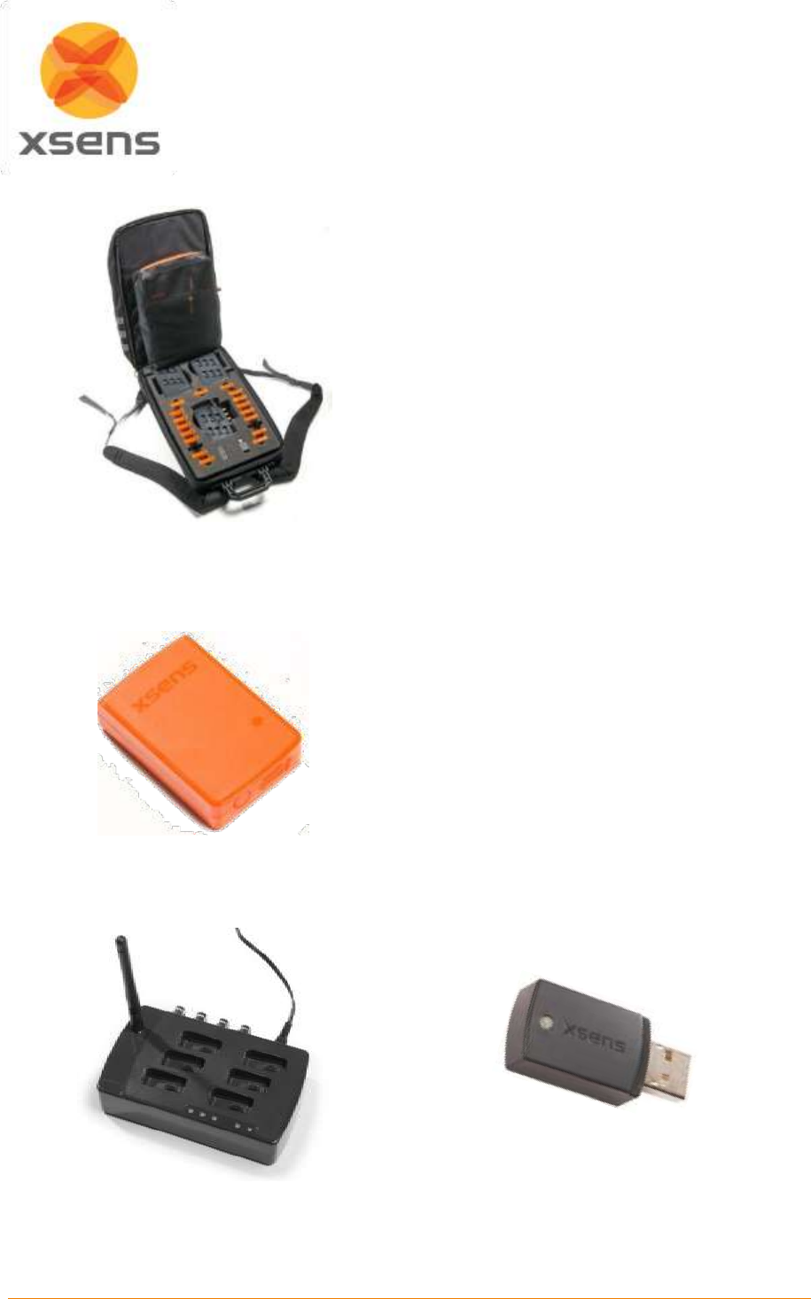
2.5 MVN Awinda backpack/suitcase with contents
Figure 7: Suitcase containing the MVN Awinda
System
The MVN Awinda arrives in durable backpack with
protective frame, which contains:
18 Wireless Motion Trackers (MTw)
1 Awinda Station
1 Awinda Dongle
2 Awinda Chargers
MTw full body Velcro straps, including 3 shirts,
headband, footpads, 2 pairs of gloves
1 Segmometer
Quick Setup sheet
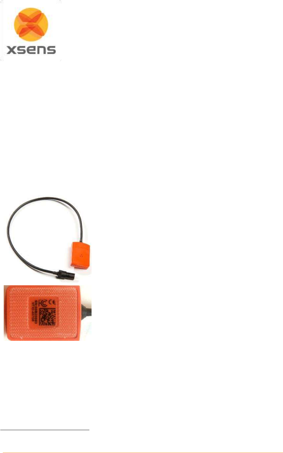
2.6 Motion Tracker (MTw)
Like the MTx, the MTw is a miniature inertial
measurement unit containing 3D linear
accelerometers, 3D rate gyroscopes, 3D
magnetometers, and a barometer. Additionally
each MTw contains an internal battery. The
trackers are placed at strategic locations on the
body (secured by the straps), to measure motion
of each body segment. For more details about the
MTw, see Section 5.7.1.
Figure 8: Motion Tracker (MTw)
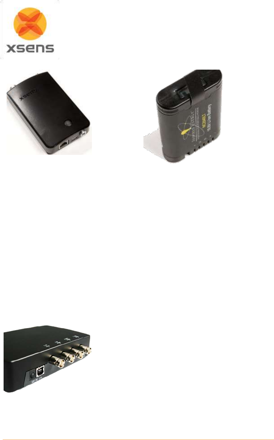
2.7 Awinda Station
Figure 9:Awinda Station
Figure 10: Awinda USB Dongle
The Awinda Station or the Awinda USB Dongle controls the reception of synchronized wireless data
from all wirelessly connected MTw’s. See Section 5.7 for further details.
Document MV0319P.N
© Xsens Technologies B.V.
MVN User Manual
5
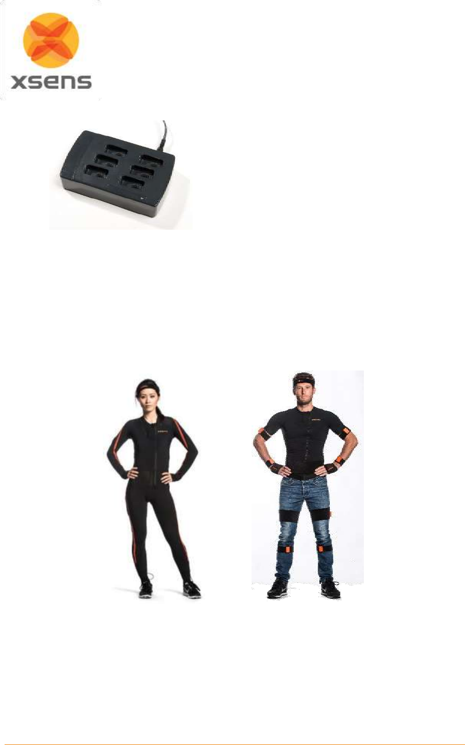
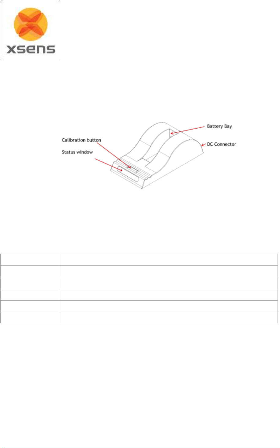
2.8 MVN Awinda Charger
The MVN Awinda Charger is capable of
charging six motions trackers. Charging from
empty to full takes about one hour.
Figure 11: MVN Awinda Charger
2.9 “The Suit”
Depending on the system, either a Lycra suit or a set of mounting straps are provided.
The Lycra suit, has been designed for MVN Link and the straps for MVN Awinda. The generic term for
either mounting type is simply “The Suit”. Each mounting system is dedicated to ensuring a good fixation
to the body, to minimize skin motion artefact.
For more information about each Suit type see Section 5.9.
Figure 12: MVN Lycra suit
Figure 13: MVN Awinda Straps
Document MV0319P.N
© Xsens Technologies B.V.
MVN User Manual
6
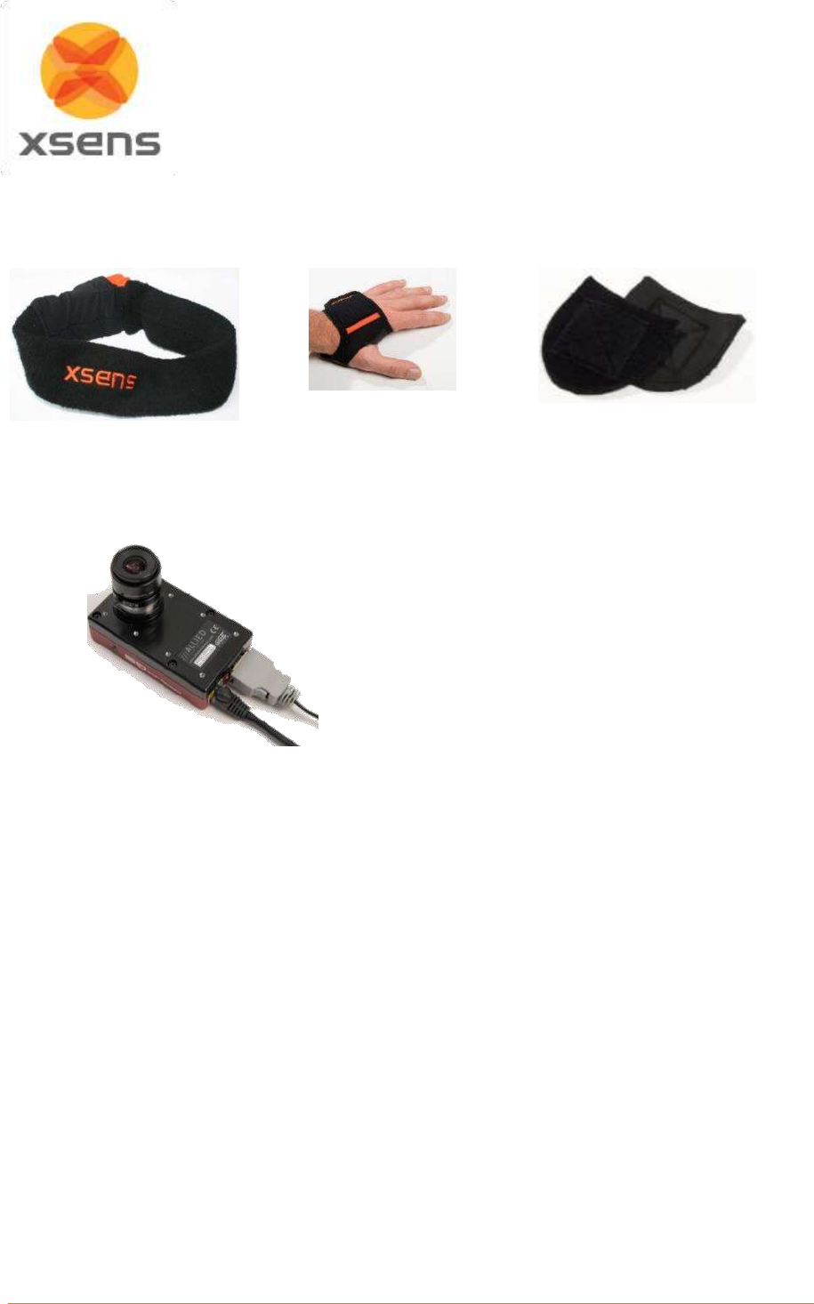
2.10 Motion Trackers on the extremities
The motion trackers are secured to the extremities – the head, hands and feet, using a headband, gloves
and a foot pads, as can be seen in the figures below.
Figure 14: Headband
Figure 15: Gloves
Figure 16: Foot Pads
2.11 MVN Ethernet Camera
The MVN Ethernet camera is the Allied GigE
Ethernet camera (supplied with MVN BIOMECH).
Permits capture of synchronized video with MVN
data.
For more information about the MVN Camera,
see Section 5.7.10.
Figure 17: MVN Ethernet Camera
2.12 Software
The MVN system is controlled by a software application called MVN Studio. MVN Studio is a 64-bit
application for Windows 7 and 8. There are three versions of MVN Studio: MVN Studio, MVN Studio
PRO, and MVN Studio BIOMECH.
Additional software packages are available for users with specific needs:
For users wishing to use the facilities offered by MVN, such as the biomechanical model and various
other dedicated functionalities, for visualizing and collecting data the MVN Software Development Kit
(MVN SDK) is available, where users can create their own user interface.
MVN Studio PRO comes enabled with the capabilities of a real-time streaming interface from MVN to
Autodesk Motion Builder® and Maya®. Additionally, the MVN remote control and MVN time-code plug-
in are enabled for users who wish to accurately measure the time over which recordings are made (for
example to facilitate synchronization with other devices such as cameras and audio equipment that also
accept time-code as a synchronization means).
To stream to Siemens PLM software, the Siemens Tecnomatix streamer is available with MVN Studio
BIOMECH.
Document MV0319P.N
© Xsens Technologies B.V.
MVN User Manual
7
3 Getting started
3.1 Installation of software
Note: Do not connect your MVN System (either Access Point or Awinda Station) until software
installation is complete (software installation includes installation of relevant drivers which can
be finalized, when the hardware is connected).
Run the downloaded MVN Installer (mvn_studio#_setup.exe). Install with “Administrator” rights. Follow
the on-screen instructions.
See 4.1 for details.
3.2 Setup hardware
If using the MVN (BIOMECH) Link system:
Connect the Access Point to the computer using the network cable optionally with the Ethernet-to-
USB adapter. See Section 5.6.
After the suit has been put on, connect the head, hands, and feet trackers to the MTx-STR’s
Place the Body Pack on the right and the Battery Pack on the left of the back (for more information
on putting on the suit, see section 5.9 or the tutorial video (https://tutorial.xsens.com/mvn)).
Connect the Battery Pack and all strings of trackers to the Body Pack
Press the button on the Body Pack once to power on the device, a pulsing fading LED, solid LED,
beep and finally blinking LED indicate the startup process. See Section 5.3.
If using the MVN (BIOMECH) Awinda system:
Connect the Wireless Master to the computer or laptop
Turn on the trackers by pressing the button until each LED is activated and begins to flash
Place the straps and trackers on the body (for more information on putting on the straps, see section
5.9 or the dedicated tutorial video).
Optional if using MVN Studio BIOMECH
Connect the power supply and network cable of the MVN Camera. See Section 5.7.10.
3.3 MVN Studio workflow overview
Run MVN Studio. See Section 6.
Start a new session. See Section 7.1.1.
For MVN Studio PRO or MVN Studio BIOMECH users requiring additional hardware
(reference camera or sync), initialize this hardware at the new session stage.
Check the hardware status to make sure that all trackers that are needed for the given
configuration have been detected by MVN Studio. See Section 7.8.
Calibration. See Section 8.
For this step users should be in an area free of magnetic disturbance. See Section 19.2.
Ensure that the ‘Calibrate’ icon is active in the workflow tool bar.
On the Body Dimensions tab enter the subject height and foot size. See section 8.1.
Document MV0319P.N
© Xsens Technologies B.V.
MVN User Manual
8
Click the Calibration tab. Select N-pose or T-pose and follow the instructions to
perform a sensor to segment calibration. Additional calibration poses are also
possible if expert calibration routines are enabled. See Section 8.2.
Pay attention to the calibration quality displayed in the Messages for Calibration
window before applying the calibration to the character. See Section 8.2.6.
Preview and Record. See Section 9.
The live character can be seen in MVN Studio viewport. See Section 9.1.
To record a trial, click the red “Record” button. See Section 9.2.
Playback and editing. See Section 10.
The recorded trials can be played, using familiar playback buttons. See Section 10.1.
Contact editing is used to manually determine when contact is made between the
subject and the surroundings. See Section 10.3.2.
Analysis. See Section 11.
Graphical representation of all data, real-time and offline. Section 11.1.
Saving and Exporting. See Section 12.
MVN trials are saved directly as files with the .mvn extension. Files with this extension
can be opened in MVN Studio. Data can also be exported to:
BVH (BioVision Hierarchical data) embeds captured motion data in ASCII format
which can be imported in many animation applications. BVH requires a strict
hierarchal structure, and only relative joint angles can be exported into this file format.
This will cause differences between the BVH output and the originally captured
motion. See Section 12.2.
C3D (Coordinate 3D) is a format used prolifically in optical systems. The format is
coordinate 3D; therefore bony landmark points have been calculated and exported
from MVN (virtual marker set). See Section 12.3.
FBX (Filmbox) is a platform-independent 3D file format enabling access to Autodesk
software (MotionBuilder, Maya or XSI). For some software packages, an FBX plug-in
should be installed. FBX files exported from MVN contain position and orientation
information of all 23 segments. See Section 12.4.
MVNX is a human readable, XML format which can be imported to many other
software programs, including MATLAB and Excel. This format contains the most
information, including the sensor data, segment kinematics and joint angles, as well
as the subject information needed to recreate a 3D visualization of a character. See
Section 12.5.
Movie Exporter is an mpeg-4 (.m4v or .avi) video export tool which contains a capture
of the character’s live motion as configured in the display window.
3.4 Tips for best practice
3.4.1 Operating conditions
The recommended operating temperature of the MVN System is between -10°C and +50°C ambient
temperature. If operated outside this temperature range performance may decrease or the device might
be damaged. Fast transient temperature fluctuations may cause significant temperature gradients
across the device. Such gradients cannot be properly modelled by temperature compensation and may
Document MV0319P.N
© Xsens Technologies B.V.
MVN User Manual
9
therefore decrease performance. For optimal performance the ambient temperature should remain
constant as much as possible during the measurement.
NOTE: Never expose the motion tracker to strong magnetic fields. Xsens MT’s contain the absolute
possible minimum amount of ferromagnetic materials (‘hard’ and ‘soft’ magnetic materials).
Nonetheless, some minor components can be magnetized permanently by exposure to strong magnetic
fields. This will not damage the unit but will render the calibration of the magnetometers useless. This
can typically observed as a (large) deviation in heading. Therefore it is necessary to prevent exposure
of Xsens Motion Trackers to strong magnetic fields, such as close proximity of permanent magnets,
speakers, electro motors, etc.
It is best to ensure that measurements, in particular calibration steps, are conducted in an area free of
magnetic distortions. To ensure a magnetically clean environment, ensure that the colored markers are
green at the pelvis, hands and feet during calibration and preferably also during recordings.
The Awinda Station, Awinda USB Dongle, Awinda Chargers, Access Point, Body Pack, Battery Pack,
and MT’s must be kept dry at all times. Condensation and water may damage the internal electronics.
The MT’s should be protected from electro static discharges or sources of radiation, as exposure to such
sources will damage the internal electronics.
The MT’s should be protected from violent handling such as drops on hard surfaces. Excessive shocks
or violent handling may damage the MT’s. When handling an MT at a desk, it is advised to place
cushioning material on the desk.
With MVN Awinda, if it appears that data performance is less than expected, try changing the radio
channel to ensure a channel is used with minimal radio interference.
3.4.2 Absolute maximum ratings
Stresses above Absolute Maximum Ratings may cause permanent damage to the device.
Description
Value (MVN Link)
Value (MVN Awinda)
Shock (any axis):
100000 m/s2 (10000 g)
unpowered/powered
100000 m/s2 (10000 g)
unpowered/powered
Operating/Storage Temperature:
0 C - +50 C
0 oC - +50 oC
Stresses beyond those listed here may cause permanent damage to the device. These are stress ratings
only and functional operation of the MT at these or any other conditions beyond those indicated in the
specifications are not implied. Exposure to absolute maximum rating conditions for extended periods
may affect device reliability.
NOTE: Drops onto hard surfaces can cause shocks of greater than 100000 m/s2 (10000 g) exceeding
the absolute maximum rating of the device. Care should be taken when handling to avoid damage.
Drops causing shock greater than absolute maximum ratings may not destroy the device but will
permanently alter the properties of the physical motion sensors, which may cause the device to become
inaccurate.

Document MV0319P.N
© Xsens Technologies B.V.
MVN User Manual
10
3.4.3 Suit, shirt, short maintenance
To wash the suit, shirt, shorts remove all cables, BP and MT’s. Follow the instructions on the label
inside the suit:
Machine wash at 30°C – 85 F
Do not bleach
Do not iron
Do not dry clean
Do not tumble dry
For the headband and gloves, remove the MTx and use only cold hand wash.
3.4.4 FabriFoam Velcro Straps
Do not place in washing machine or dryer as this may damage the material. Hand wash in warm water.
Use mild detergent if soiled. Rinse well. Gently squeeze out excess water. Air dry, foam side up, on rack
or towel or hang to dry. It is best to wash regularly to keep the material clean and free of body salts, oils,
etc. This will help to prolong material life.
3.4.5 Dynamic movements
The MVN Suit/Straps should provide enough fastening for most movements. However, depending on
the individual anatomy and fit with the Suit/Straps it might be necessary to take additional steps to
ensure that the motion tracker follow the movement of the underlying body segment as well as possible.
In particular, for users who will carry out extreme movements, martial art, professional athletes or
jumping from heights; it is worth considering applying the provided straps over the Lycra suit as
reinforcements to make sure the motion trackers follow the movement of the underlying segment. These
straps should be tightly bound tape (be careful to not block the blood circulation!) over the locations of
the MT on the body. Additionally, in contact sports or other situations where there is a chance of physical
impact it might be beneficial to apply some protective measures (e.g. padding) to protect the person
wearing the MVN system as well as the MVN system itself.
3.4.6 Finding a magnetic “sweet spot”
In MVN Studio the icon of a magnet can be enabled to give an indication of magnetic environment.
When this is enabled, glowing balls appear at the hands, feet and pelvis. Green indicates a safe
magnetic environment. Subjects are advised to remain only in areas where indicators are green. If the
room is mainly red, at least find an area of green for calibration. Sometimes this can mean to go outside;
although often this step is not needed. See Section 19.2 for more details.
3.4.7 Warming up the filters
MVN Studio is based on Kalman filter algorithms. It is best to warm up the system, before making
recordings. To warm up the system, stand still for 30 seconds after the initial calibration pose. See
Section 19.9 and in particular 19.9.2 for more details.
3.4.8 CH5000 Charger Safety
Do not expose the charger or power supply to water or liquids.
Do not open the charger or power supply case, no user serviceable parts are inside.
Do not cover the fan exhaust or obstruct the airflow, this will cause overheating.
Use only the manufacturer’s power supply and observe terminal polarity.
Place the charger in a cool spot, away from external heat sources
Caution - during recalibration the charger may become warm.

Document MV0319P.N
© Xsens Technologies B.V.
MVN User Manual
11
4 Software
As mentioned in Section 2.12, the MVN system is controlled MVN Studio. The installer of the software
can be downloaded from www.xsens.com/mvn-studio-download. The instructions below detail the
installation procedure.
4.1 Software Installation
Note: Do not connect your MVN System (either Access Point, Awinda dongle, or Awinda Station)
until software installation is complete.
Run the downloaded MVN Installer (setup.exe). Always run installation as a user with “Administrative”
rights (by right clicking on icon and selecting “Run as Administrator”).
The MVN Studio installer will install:
MVN Studio
Documentation
Example files
Drivers for:
Xsens Access Point
MTw trackers
MVN Awinda Station and Dongle
MVN ethernet camera (Allied/Prosilica)
Dlink drivers
Bonjour drivers
Software activation tool
Notes:
With Windows 7, the installer for the MVN Ethernet camera may be hidden behind the MVN installation
window. If installation appears to pause, check that this is not the reason (move the installer window to
one side). When starting MVN Studio for the first time, allow the Windows firewall to give permission to
MVN Studio to start and connect to the internet.
Plug-ins, including: MotionBuilder plug-in, Time Code and Remote Control plug-in and MVN SDK are
optional. Separate installers are available for the MVN MotionBuilder and Maya plug-ins, the Unity plug-
in and the MVN SDK. The Time Code and Remote Control plug-in is part of the MVN Studio installer
and is activated through licensing.
4.2 Software Activation
MVN Studio needs to be activated before use. Activation can be done by three types of license keys;
Software; Dongle; Network. More information about the licensing can be found in section 15.3.
4.2.1 Software License Key
When using a software license key, license activation is necessary. The Software Activation tool can be
started from Start Menu > Xsens > MVN Studio 4.x > Software Activation. Follow the on-screen
instructions to start the activation, use the product key sent to you by customer service in email and
‘MVN Letter’.
4.2.2 Dongle License Key
Once MVN studio has installed and your license dongle is connected, the software will immediately
recognize the license and open MVN Studio.

Document MV0319P.N
© Xsens Technologies B.V.
MVN User Manual
12
Extension licenses or upgrade licenses can be activated on the dongle using the Software Activation
tool, which can be started from Start Menu > Xsens > MVN Studio 4.x > Software Activation.
4.2.3 Network License Key
When using a network license key, the red dongle needs to be used on a pc (server) that is running a
service called ‘Sentinel LDK License Manager’. This service needs to be started by running an installer,
which can be downloaded from:
Xsens website: https://www.xsens.com/mvn-studio-download/
Look for the download ‘Sentinel HASP/LDK - Windows GUI Run-time Installer’.
Document MV0319P.N
© Xsens Technologies B.V.
MVN User Manual
13
5 Hardware
5.1 MVN Link
The standard MVN System consists of a combination of hardware and software. The previous section
described how to install the software. The following will provide an overview of the hardware, which
includes the MTx’s, Body Pack, Sync Station and Access Point; and how to assemble the devices into
the mounting system (Lycra suit or MVN Mounting straps).
5.2 Motion Trackers (MTx)
The MTx is a complete miniature inertial measurement unit with integrated 3D rate gyroscopes
measuring angular velocities 3D linear accelerometers measuring accelerations including gravitational
acceleration, 3D magnetometers measuring the (earth) magnetic field, and a barometer to enable
measurement of atmospheric pressure.
Two types of motion trackers are integrated in the suit, the MTx, and MTx-STR. These are identical on
the inside but have different connectors, as can be seen in Figure 2 and Figure 3.
The back of the MTx displays various regulatory notices and 2D
barcodes used by Xsens for quality control and tracking, as well
as the MTx product code (MTx2-4A7G6) and serial number1
(SN).
A Velcro strip is attached to the back of the MTx tracker around
the sticker in order to allow for easy mounting of trackers onto
the suit.
1
Also known as Device ID.
Document MV0319P.N
© Xsens Technologies B.V.
MVN User Manual
14
5.3 Body Pack (BP) and Battery
Figure 18: Body pack and battery
The Body Pack (BP) interconnects multiple strings of MTx’s and retrieves their data ensuring exactly
synchronized samples. The collected data is transmitted by an optimized 2.4 or 5.0 GHz spread
spectrum wireless link to the Access Point connected to the PC or via Ethernet cable.
On the top of the Body Pack there are 4 connectors. With Xsens facing upwards, from right to left:
The large connector is a 5 pin connector which connects to the Battery Pack cable
The two central connectors are 5 pin connectors to connect to the strings of trackers
The leftmost connector is planned for future use
On the bottom of the Body Pack, there are 3 connectors:
One Ethernet connector which can be used for cabled recordings, when the system is directly
connected to the recording PC rather than transferring data via wireless signal
A micro USB connector, supported for future use to configure the BP
The 3rd connector supported for future use
The BP is powered by a single Battery Pack (rechargeable smart Lithium Ion battery pack). The Battery
Pack has a typical operating time of 9 hours (using the wireless connection) and can be charged using
the provided charger.
5.4 Sync Station
MVN Link (version 4.1 onwards) supports
synchronization with third party devices using a Sync
Station. The figure to the left shows the BNC connectors
of the Sync Station.
Section 7.5 explains how to set up synchronization of
the Sync Station and Section 23 provides more details
and examples with third party systems.
Note that if synchronizing with a third party device sending 5V, it is advised to purchase (from eg Farnell)
a 3.3 - 5V / 5V - 3.3V SMD level translator to prevent damage to the SyncIn ports of the Sync Station.
Document MV0319P.N
© Xsens Technologies B.V.
MVN User Manual
15
5.5 Battery Charger
The CH5000 is a standalone desktop smart, standard battery charger with the added ability to recalibrate
the fuel gauge on smart battery packs.
5.5.1 Using your Charger
Place the charger on a flat, level surface away from sources of heat and moisture. Plug the DC connector
from the power supply into the back of the charger and connect the power supply to the mains AC supply
using the cable supplied.
5.5.2 Charging
Place the battery into the battery bay ensuring that the 5-way connector is fully seated. The LEDs in the
status window will provide status information and the charger will automatically begin charging.
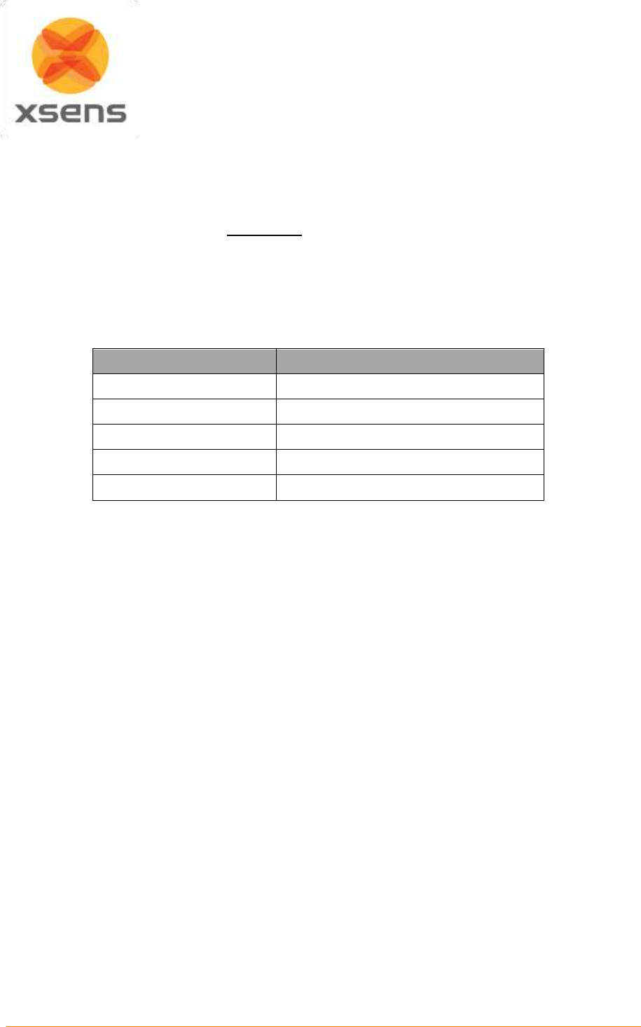
LED Indication:
The status of the battery is indicated by the LEDs visible in the status window:
Green flashing
Battery charging
Green solid
Battery fully charged
Blue flashing
Battery in calibration mode
Blue solid
Battery fuel gauge calibrated
Red flashing
Battery fuel gauge needs recalibration
Red solid
Error
Recharge and recalibration Time:
The recharge time for the battery (NC2040) is 3 hrs. The time given is for a full charge from 0% to 100%
state of charge.
Recalibration is 16-20 hrs. A calibration cycle will be faster if the battery is fully charged to begin with.
5.5.3 Fuel Gauge Recalibration
If fuel gauge recalibration is needed, the red LED on a calibrating charger will flash upon insertion of the
battery. This provides feedback on the accuracy of the fuel gauge.
At this point you can choose to either calibrate the fuel gauge or to charge the battery. Calibration takes
longer than charging and it may not be convenient to go through the calibration cycle at that moment.

Document MV0319P.N
© Xsens Technologies B.V.
MVN User Manual
16
To recalibrate the fuel gauge, press the button on the front of the charger. The charger will automatically
begin to charge the battery if the button is not pressed.
The blue LED will flash to indicate that the battery is undergoing the recalibration cycle. During calibration
the discharge resistors will be cooled by the fan. Removing the battery, or pressing the calibration button
again will re-start the process from the beginning.
At the end of this procedure the blue LED will stay constant, indicating a fully calibrated fuel gauge.
Warm environments can cause calibration failure - keep the charger away from direct sunlight or heat
sources.
Impedance-Tracking fuel gauge recalibration is achieved by charging the battery, allowing it to rest,
discharging it and allowing it to rest again as shown below:
Charge the battery to full charge and allow it to rest for at least 5¼ hrs.
Discharge the battery to empty and allow it to rest for 5¼ hrs
At this point the fuel gauge is calibrated, but the battery is partially discharged and will
require a recharge
The temperature during the process must remain between 10°C & 40°C.
5.5.4 What is fuel gauge recalibration and why is it needed?
As the battery ages and is used, its available capacity shrinks - so with each cycle, your device’s runtime
gets a little bit less.
A good rule of thumb is that Li Ion batteries lose 5% capacity per 100 cycles & 5% per year.
For more details on smart charging and recalibration go to www.inspiredenergy.com
Document MV0319P.N
© Xsens Technologies B.V.
MVN User Manual
17
5.5.5 BP Power on/off and status LED
Each BP has one push button with integrated LED, which controls its power state.
Power on:
Press button once, a single beep will sound and the LED will begin to
blink slowly: 1 second on, 1 second off
Power off:
Press button three times, three beeps will sound and the LED will stop
blinking.
5.5.6 BP Status LED
The status LED changes color depending on the BP state. See Table 1 for an overview.
Table 1: LED indicators on the Body Pack
LED indication
active mode
Off
Power down
Slow fading flash
Body Pack turning on
Solid
Wireless mode – searching for host
Flashing
Wireless mode – connected to host
Strobe flashing
Wireless mode – sending data
5.5.7 Setup for wired connection via Ethernet
This section refers to the wired connection between Body Pack and PC, via Ethernet cable.
MVN is configured to operate in wireless transmission mode by default. However, an Ethernet
connection can be made between the BP and the AP in order to directly transfer data to the PC.
Note: The Ethernet connection should be established prior to turning on the BP.
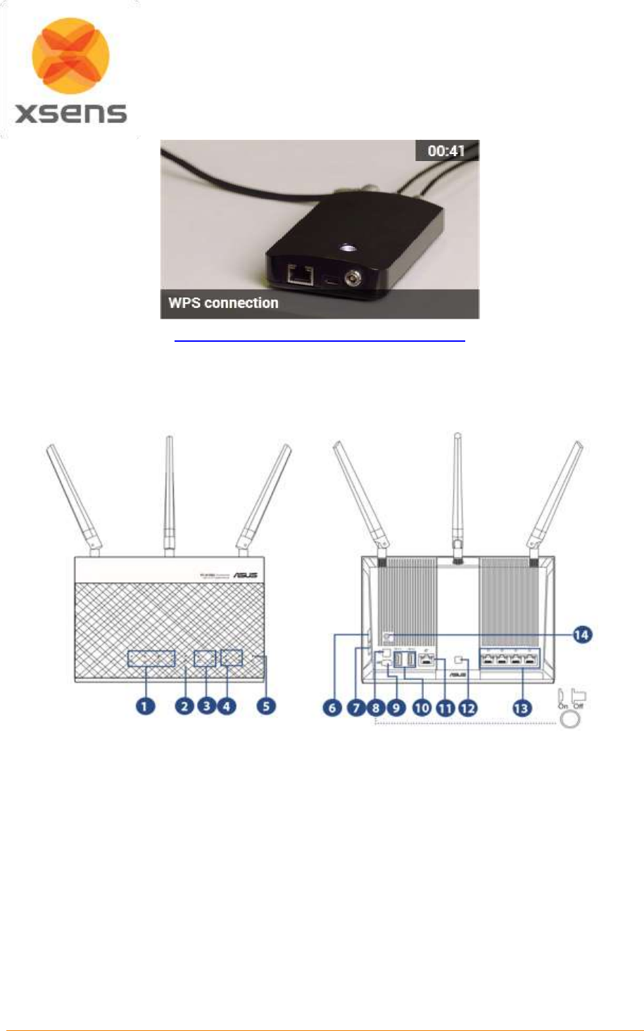
5.5.8 Running a Wi-Fi Protected Setup (WPS)
In order to establish a connection between a Body Pack and an Access point, users must conduct a Wi-
Fi Protected Setup (WPS).
After the AP is turned on, press and hold the WPS button located on the side of the unit for 2
seconds, until the connection light begins to flash (3 rapid strobes followed by a pause). From
the time this flashing begins you have 2 minutes to create a connection with the body pack.
Next, initialize the Body Pack and wait for the unit to beep and begin searching for a wireless
connection. Once the BP is initialized, press and hold the power button for 2 seconds and wait
for the LED to begin flashing like the AP LED.
A successful WPS is indicated by a beep and the BP LED will return to intermittent flashing.
See the Tutorial video “WPS connection”. Click Image or address for a direct link to the tutorial.
Document MV0319P.N
© Xsens Technologies B.V.
MVN User Manual
18
https://tutorial.xsens.com/video/wps-connection
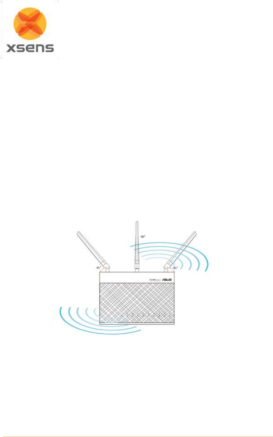
5.6 Access Point (AP)
The MVN System comes with one Access Point (AP) which handles the data traffic between the BP and
the computer. The Access Point should be connected to the PC via Ethernet cable through the Ethernet
port or using the supplied Ethernet to USB adapter.
1. LAN 1~4 LED
Off: No power or no physical connection.
On: Has physical connection to a local area network (LAN).
4. 2.4GHz LED / 5GHz LED
a. Off: No 2.4GHz or 5GHz signal.
b. On: Wireless system is ready.
c. Flashing: Transmitting or receiving data via wireless connection.
5. Power LED
a. Off: No power.
b. On: Device is ready.
c. Flashing slow: Rescue mode
d. Flashing quick: WPS is processing.
6. WPS button
a. This button launches the WPS Wizard.
8. Power button
Document MV0319P.N
© Xsens Technologies B.V.
MVN User Manual
19
a. Press this button to power on or off the system.
9. Power (DC-IN) port
a. Insert the bundled AC adapter into this port and connect your router to a power
source.
12. LED On/Off button
a. Press this button to turn on/off the backlight LED on the panel.
13. LAN 1 ~ 4 ports
a. Connect network cables into these ports to establish LAN connection.
14. Reset button
a. This button resets or restores the system to its factory default settings
5.6.1 Positioning the Access Point
For the best wireless signal transmission between the wireless router and the network devices
connected to it, ensure that you:
Place the wireless router in a centralized area for a maximum wireless coverage for the
network devices.
Keep the device away from metal obstructions and away from direct sunlight.
Keep the device away from 802.11g or 20MHz only Wi-Fi devices, 2.4GHz computer
peripherals, Bluetooth devices, cordless phones, transformers, heavy-duty motors, fluorescent
lights, microwave ovens, refrigerators, and other industrial equipment to prevent signal
interference or loss.
To ensure the best wireless signal, orient the three detachable antennas as shown in the
drawing below.
Note: If the AP is connected to the computer through the supplied Ethernet to USB adapter, it will not
function when a “Selective Suspend” power management feature is enabled on the PC/Laptop being
used for recording. When the AP is used with “Selective Suspend” turned ON, the computer may hang
during shutdown or possibly not shutdown correctly. You must therefore disable power management for
the USB hub to prevent this. To do this, follow these simple steps:
From the Start Menu >Right click on Computer >Manage >Device Manager >Universal Serial Bus
Converters >Right click on USB Root Hub >Properties >Power Management.
Uncheck the box “Allow the computer to turn off this device to save power.” OK your way out.
NOTE: Doing this may significantly reduce laptop battery life.
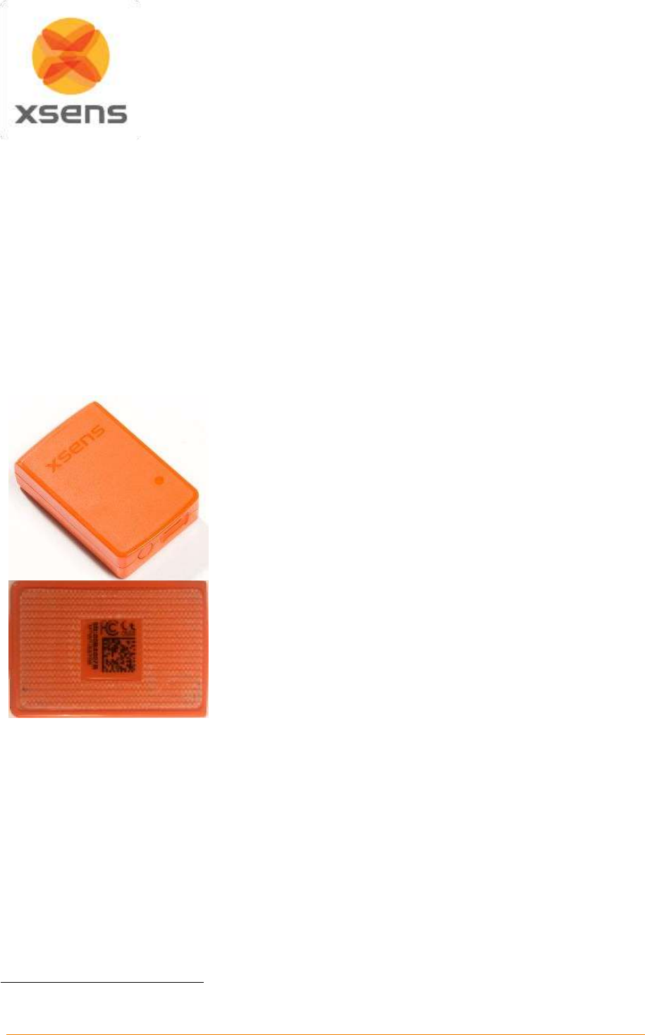
Document MV0319P.N
© Xsens Technologies B.V.
MVN User Manual
20
5.7 MVN (BIOMECH) Awinda
5.7.1 Wireless Motion Trackers (MTw)
The MTw provides 3D angular velocity using rate gyroscopes, 3D acceleration using accelerometers,
3D earth magnetic field using magnetometers, as well as atmospheric pressure using the barometer.
Combined with Xsens algorithms, 3D drift-free orientation is provided. The MTw is an excellent
measurement unit for orientation measurement of human body segments, in particular because it is also
designed to maintain very high accuracy time synchronization of the individual sensor readout across a
wireless network of multiple units. This is essential when measuring joint angles accurately.
The MTw is powered using a LiPo battery. The battery can be in operation for up to 6 hours, and maintain
a level of charge in stand-by for approximately 90 hours when in sleep mode. It will be fully recharged
after one hour docked in a wall powered Awinda Station. For more technical details on the MTw, sensor
component specifications and orientation performance, see Section 19.13.
On the top of the MTw is an LED which indicates of device
status.
The MTw charges via micro USB connection located on its base.
Next to this is a power button used to power each MTw on and
off.
The back of the MTw displays 2D barcodes used by Xsens for
quality control and tracking, as well as the MTw product code
(MTw2-3A7G6) and serial number2 (SN).
On the side of each MTw is a label indicating the pre-defined on
body position.
Velcro attached to the back of the MTw tracker allows easy
fixation to the straps.
2
Also known as Device ID.
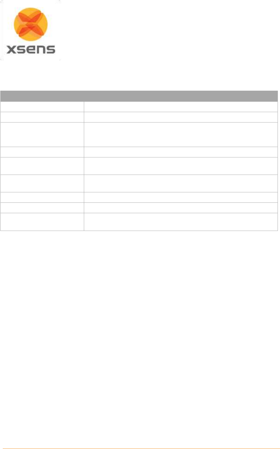
Document MV0319P.N
© Xsens Technologies B.V.
MVN User Manual
21
5.7.2 MTw LED Indications
The following lists the LED indications of the MTw, which are a combination of the device states and the
Awinda protocol states of the MTw.
State
Description
Power-up
Blinking.
Docked and fully charged
ON
Charging
Slow fade from ON to OFF as a percentage [%] of battery status.
A slow cycle means an almost full battery. A quick cycle means an
almost empty battery.
Scanning
Pulsating out of sync with Awinda Station (CONN LED)
Connected
Slow symmetric ON/OFF toggle in sync with Awinda Station (CONN
LED).
Measuring
Fast symmetric ON/OFF toggle in sync with Awinda Station (CONN
LED).
Battery Low
Quick Triple Pulses, overrides other states until charging again.
Flushing
Double pulse in sync with Awinda Station (CONN LED).
Stand-by
OFF. Blinks for 3 s, if motion has been detected, while searching for
a radio connection.
5.7.3 MTw Stand-by Mode
Following a wireless connection to the Awinda Station or Dongle, the MTw enters measurement mode.
If the radio of the Awinda Station or Dongle has been switched off for longer than 30 seconds the MTw
will enter stand-by mode. In this mode, the MTw will shut down its power and stop the LED blinking, but
monitor change in magnetic field every second. See below for exiting standby mode.
5.7.4 Exiting stand-by mode
The MTw will monitor its movement, if there is considerable movement, and there is a signal from an
Awinda Station or Dongle, the MTw will become active again.
To manually bring the MTw out of stand-by mode, reactivate the radio of the Awinda Station, and move
the MTw. A simple 90 degree turn or simply lifting it from the suit case to apply to the subject should be
enough.
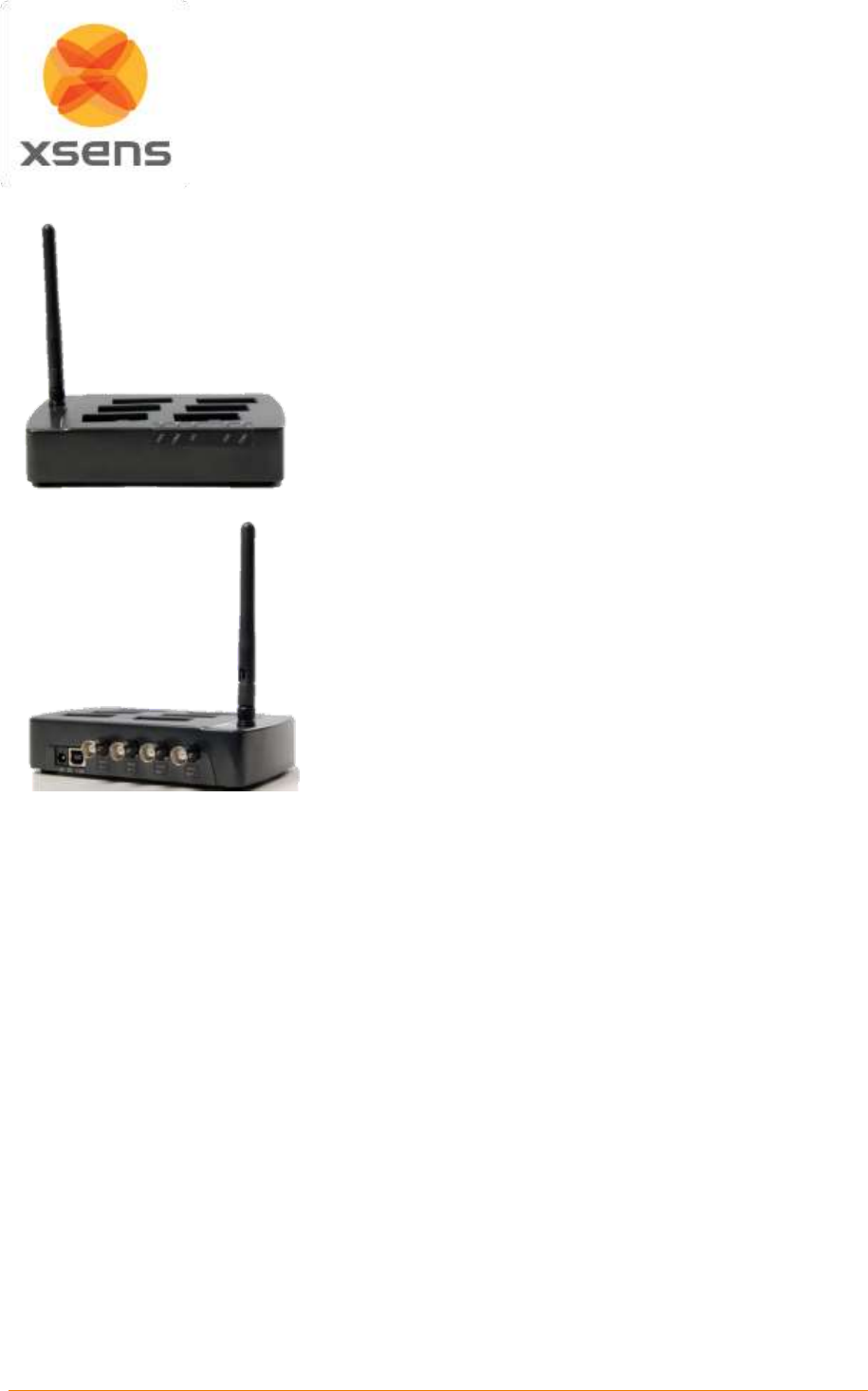
Document MV0319P.N
© Xsens Technologies B.V.
MVN User Manual
22
5.7.5 Awinda Station
Front view of the Awinda Station, showing the LEDs. A
description of the LEDs is provided in Section 5.7.7 below.
On top are docking spaces for 6 MTw’s with recessed micro
USB connectors. On the side is a foldable and rotatable 2.4
GHz antenna for maximum range.
The external antenna of the Awinda Station enables a
wireless range indoor/outdoor: 20/50 m (60/150ft).
Back view of the Awinda Station, showing the DC power
connector, the USB connector and 4 BNC sync I/O
connectors for synchronization with external devices.
5.7.6 Awinda Station Synchronization Ports
On the back of the Awinda Station there are four BNC ports, two Sync In ports and two Sync Out. The
ports have been configured to send (Sync Out) or receive (Sync In) TTL pulses 0-3.3V.
Note that this 3.3V is s lower than some devices, which will be synchronized with the MVN System.
These other devices use 5V. For this reason it is advised to separately purchase (from eg Farnell) a
3.3 - 5V / 5V - 3.3V SMD level translator. This will prevent damage to the SyncIn ports of the Awinda or
Sync Station when receiving 5V pulses from third party systems. In general sending a 3.3V pulse from
an Awinda or Sync Station SyncOut port is fine. Therefore unless a threshold of 5V of the third party
system is required, in which case the 3.3V-5V SMD level translator will be required.
For software configuration of the synchronization channels, see Section 23.
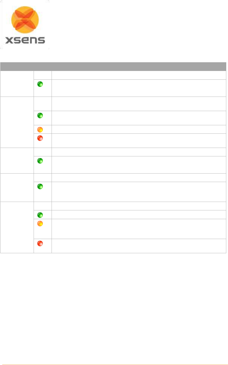
Document MV0319P.N
© Xsens Technologies B.V.
MVN User Manual
23
5.7.7 Awinda Station Status LED
The Awinda Station has five LED indicators. From right to left, these indicators are:
LABEL
LED
DESCRIPTION
CHRG
[CHaRGer
functionality]
OFF
When no mains power supply is connected to the Awinda Station.
GREEN: When 12V power supply is connected (mains power supply).
STAT
[STATus of
the Awinda
Station]
OFF
OFF: When no power supply is present and when MVN Studio is not started.
Power is from mains power supply and / or USB.
GREEN: Both USB connection present and MVN Studio running connected
to driver.
ORANGE: USB connection to host PC is present.
RED: Only power supply connected or error has occurred, e.g., a short-
circuit of an MTw.
EXT
[EXTernal
connection]
OFF
Remains off unless external connection made.
GREEN: External connection e.g. sync port.
CONN
OFF
OFF: No wireless connection.
GREEN slow blinking: (1 blink per second), radio switched on. When MTw
connects, MTw LED and CONN LED blink synchronously.
Fast blink: Measurement Mode.
DATA
OFF
OFF: No data received.
GREEN: Measurement mode.
ORANGE: Flushing. Flushing is the action of transferring data that has been
stored on the MTw buffer, while the MTw was out of range and unable to
transfer data in real-time to the Awinda Station.
RED: Recording mode is active. This allows the remote monitoring that the
host PC has initiated a recording successfully.
Note:
The power supply is needed to charge docked MTw’s or to change between power off and power on, of
docked MTw’s. Only the power supply is needed for charging purposes (USB is not needed in this case).
Power supply and USB connection are required for firmware updates or location reassignment of MTw’s.
Power supply is not needed for wireless communication (e.g. measurement/recording).
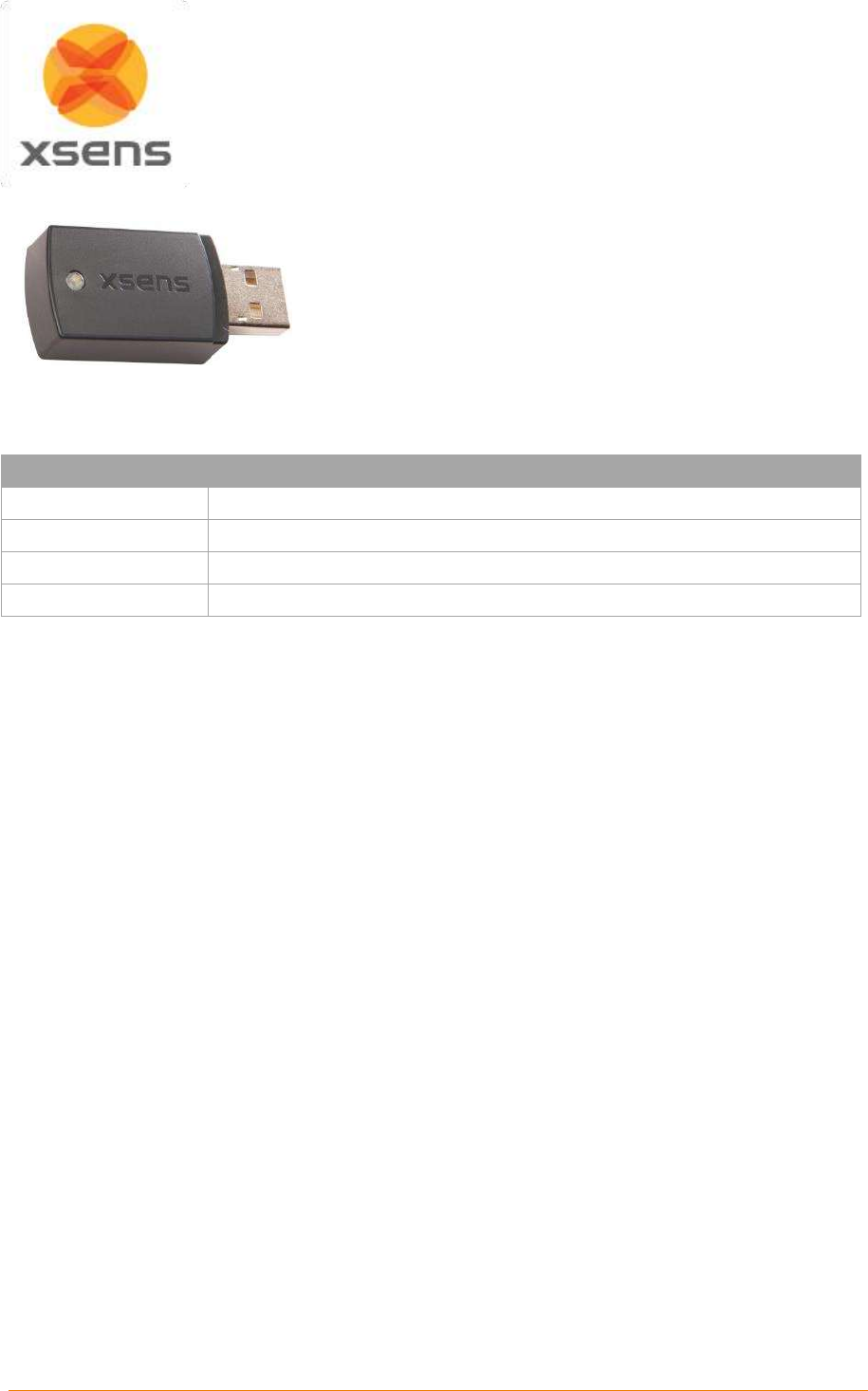
Document MV0319P.N
© Xsens Technologies B.V.
MVN User Manual
24
5.7.8 Awinda USB Dongle
The Awinda USB dongle has the same wireless capabilities as
the Awinda Station, in that it can accurately control the
reception of data of up to 32 MTws.
Given that the Dongle does not have an external antenna its
range is shorter than the Awinda station; indoor/outdoor
10/25m (30/75ft).
5.7.9 Awinda USB Dongle LED
The Awinda USB dongle has one white LED.
State
Description
Radio Off
LED off.
Scanning for MTw’s
Pulsating LED.
Connected
Slow symmetric ON/OFF toggle (MTw blinks in sync with LED of dongle).
Measuring
Fast symmetric ON/OFF toggle (MTw blinks in sync with LED of dongle).
5.7.10 Powering off MVN Awinda
Power off the MTw’s by clicking on each tracker’s power button.
5.7.10.1 Power off wirelessly connected MTw’s
To power off wirelessly, the system should be wirelessly connected. To power off, go to menu >Tasks
>Switch Off Hardware. All MTw’s will switch off. The MTw LEDs and the CONN LED of the Awinda
Station will switch off.
5.8 MVN (Ethernet) Camera
The MVN Ethernet Camera is a high quality professional GigE camera with a C mount. The GigE
interface enables the use of long cables (max 100 m) and standard 1 Gigabit Ethernet cards for
interfacing. Currently in MVN Studio the frame rate is limited to 60 Hz, but the camera itself is capable
of 120 frames per second (fps), depending on lighting conditions. The camera has a global shutter and
is capable of advanced triggering and synchronization features.
5.9 The suit
The MVN system arrives with motion trackers either mounted into a Lycra suit or located in a tray with
a set of accompanying MVN straps. The generic term for the straps or the Lycra suit is simply “The Suit”.
Below a description of how to mount the straps or suit is explained, followed by the advice for the
extremities (hands, feet and head), which are the same for both systems.
5.9.1 Straps
The MVN Strap set consists of a set of patented non-latex composite material; these are often used in
the medical profession, and are safe and hygienic. Additionally zip-fastened T-shirts in three sizes are
provided for securing the sternum and shoulders.
Straps are provided as a standard mounting system with MVN Awinda and are useful for interchanging
setups between (different sized) subjects.

Document MV0319P.N
© Xsens Technologies B.V.
MVN User Manual
25
Straps are suitable for a majority of the adult population and can be placed directly on the skin for the
close contact, or on top of the clothing for comfort. If worn over clothing, it is advisable to wear relatively
tight-fitting clothes.
The motion trackers are provided with a code
indicating segment position.
‘L’ or ‘R’: left or right side of the body.
Segment: An abbreviation of the segment name.
While the straps are not labelled, the dimensions
give an indication of their intended locations.
Segment
Width [cm]
Length [cm]
Pelvis
10
140
Upper Leg
10
72
Lower Leg
5
55
Upper Arm
5
55
Forearm
5
30
5.9.1.1 Putting on the Straps
Below are a few simple steps to help put on the straps. It is advised to watch the tutorial video for more
detailed and visual information.
https://tutorial.xsens.com/video/placing-straps
It is recommended to begin by putting on the top.
Since the sternum and shoulder trackers are attached to Velcro patches on a zip-fastening t-shirt, it
is advised to secure this garment before attaching the upper arm straps.
For the arms, legs and pelvis: Straps should first be placed (tightly) onto the limb in question, fasten
the tracker in place then wrap the remaining length of the strap tightly around the limb and fasten
using the Velcro tab.
It is necessary to have assistance for positioning the motion trackers of the shoulder blades after
the zip on the vest has been secured. It is also advisable to have assistance for accurate positioning
of the tracker at the pelvis, while the wearer (or second assistant) wraps the remaining length of the
strap around the waist.
Check that the Straps are fastened tightly enough to the body.
To do this, the subject wearing the straps should walk, run or perform sample movements to be
measured. If the straps become loose, re-tighten them and repeat the check.
NOTE: When tightening the straps, pull the strap from the center of the length rather than at the
end!

Document MV0319P.N
© Xsens Technologies B.V.
MVN User Manual
26
5.9.2 MVN Lycra suit
A Lycra suit is provided with the MVN Link system. The MVN Lycra Suit is available in 5 different sizes
(S, M, L, XL and XXL). Before putting on a suit, ensure that the size is appropriate; refer to Table 7 in
the appendix for this information. The suit must be tight fitting, therefore choose the appropriate suit
size. Note that the fabric is stretchable, a medium size suit can fit to both a short muscular athlete (e.g.,
1.60 m, 70 kg) and a tall slim person (e.g., 1.75 m, 65 kg).
Take care when putting on the suit; you are working with delicate materials. The subject is advised to
wear closely fitting shorts and a tight shirt underneath the MVN Lycra Suit. Other clothing can be worn
on top, no connection or line-of-sight is needed to the external world other than the wireless data link.
Follow these steps to put on the suit:
Important:
The zip is at the front of the Lycra suit.
Do not pull aggressively on the material, work gradually from the feet to the neck.
5.9.2.1 Putting on the Lycra suit
Below are a few simple steps to help put on the Lycra suit. Again it is advised to watch the video on the
tutorial portal for more detailed, visual information.
https://tutorial.xsens.com/video/putting-on-lyrca-suit
1. Unzip the zipper.
2. The subject should wear only tight shorts and t-shirt and socks at this stage.
3. Slide the legs through the lower part of the suit. Put the feet through the loops underneath the trouser
legs, the zip channel should be placed in the front! A tight material is chosen for optimal attachment
of the MT’s, so take time to pull up the suit bit by bit until it fits comfortably.
4. When the suit is at the correct height, put one arm through the sleeve and use the other arm to pull
the suit around the shoulder. Follow the same procedure for the other arm.
5. To minimize sliding of the MT’s on the arms, place the thumbs through the loops at the end of the
sleeves. This can also be done after putting on the gloves.
6. Zip up the zipper
7. If possible pull lightly at the suit around the shoulders and neck, so the suit can divide the stretch
well, and fit comfortably.
5.9.2.2 Placing the MT’s in the Lycra suit
Upon delivery, the Lycra suit will come with MTx inside already. However, for changing suit sizes or after
washing, you will need to put the motion trackers back in the suit. It is advised to do this when the
“empty” suit is already on the subject. The video on the tutorial portal shows how to do this best..
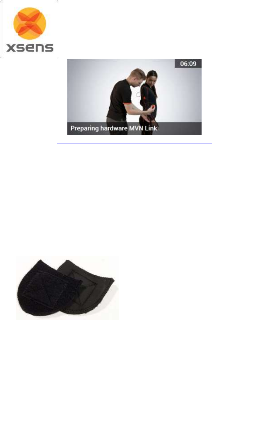
Document MV0319P.N
© Xsens Technologies B.V.
MVN User Manual
27
https://tutorial.xsens.com/video/preparing-hardware-mvn-link
1. Unzip all zipper channels on the suit
2. Secure each MT into the suit using the Velcro patches on both the trackers and the Lycra.
3. Connect the cables between strings of trackers.
4. Ensure that all MT’s are in the approximate locations as indicated in the tutorial video.
5.9.3 Putting on the remaining Motion Trackers
When the suit has been put on, motion trackers for the head, hands and feet will remain outside of the
Lycra. The head band is fitted with a Velcro patch, and gloves are fitted with a pocket for motion tracker
placement. The motion trackers for the feet are secured to the shoes using foot pads, as described in
section 5.9.4.
5.9.4 Foot pads
Dedicated foot pads have been made to facilitate placement of the motion trackers on the feet, these
pads can be used with many different types of shoes and remain fixed to the feet, minimizing motion of
the tracker on the foot and ensuring reliable motion capture data and foot contact detection.
Figure 19: Foot pads
To use, place the pads with the motion tracker
attached onto the bridge of the foot, tongue of the
shoe. It is best to push this a little further to the
front of the foot, since when the shoes are
fastened, it can slip upwards. Make sure the shoe
fastening e.g. prevent the tracker from shifting
within the shoe.
5.9.5 Putting on the Body Pack and Battery Pack
The Body and Battery Packs are placed into the pockets at the back of the Lycra suit. While it is not
crucial, it is more comfortable if you the Body Pack is on the right and the battery on the left.
5.9.6 Tracker locations
The placement of the motion trackers onto the correct segment is very important, as each tracker has a
given ID, which is used throughout the motion capturing procedure. Additionally, it is important that the
motion trackers are positioned on the segment in a place where maximal range of motion and a minimal
amount of skin motion artefact occurs. When wearing the Lycra suit, it is more likely that the MTx’s are
positioned correctly than with the Straps. Therefore please refer closely to the following information to
ensure the best placement. Table 2 describes the positioning of the motion trackers.
Document MV0319P.N
© Xsens Technologies B.V.
MVN User Manual
28
Table 2: Description of MT locations
Location
Abbreviation
Optimal position
Foot
FOOT
Middle of bridge of foot
Lower leg
LLEG
Flat on the shin bone (medial surface of the tibia)
Upper leg
ULEG
Lateral side above knee
Pelvis
PELV
Flat on sacrum
Sternum
STERN
Flat, in the middle of the chest
Shoulder
SHOU
Scapula (shoulder blades)
Upper arm
UARM
Lateral side above elbow
Fore arm
FARM
Lateral and flat side of the wrist
Hand
HAND
Backside of hand
Head
HEAD
Any comfortable position
Watch the video on the tutorial portal for instructions on how to put place the MTw’s on the straps.
https://tutorial.xsens.com/video/preparing-hardware-mvn-awinda
5.10 Connecting the hardware and software
To connect the hardware and software, connect to the Access Point or plug the Awinda Station into the
USB port of the pc. When using the MTx, make sure that the BP is switched on. Start MVN Studio to
begin working with the system.
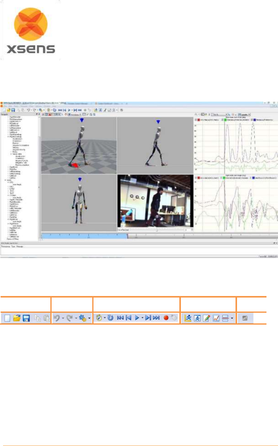
Document MV0319P.N
© Xsens Technologies B.V.
MVN User Manual
29
6 MVN Studio
MVN Studio is easy-to-use software, which can be used for real-time viewing and recording. Off-line
playback, analyzing and editing of previously recorded sessions are also possible with MVN Studio.
Figure 20 shows a typical view of MVN Studio when a recording has been made.
Figure 20: MVN Studio interface
The main tool bar at the top of the MVN Studio interface is displayed in Figure 21 below. Using this
toolbar, much of the functionality of MVN Studio can be called.
File
Edit
Record & Playback
Workflow and
views
Snooze
toggle
Figure 21: Main toolbar in MVN Studio
The “Snooze toggle” is for energy saving purposes. Activate snooze to save power, for example, if MVN
Studio is running, but the subject is temporarily not required to perform measurements. Note that this
setting controls only the MVN Link system. It does not save power when using MVN (BIOMECH) Awinda.
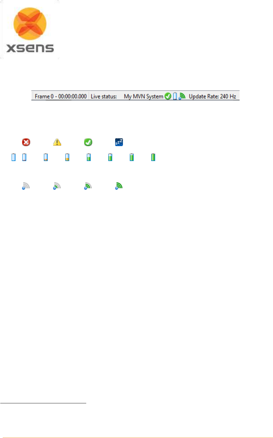
Document MV0319P.N
© Xsens Technologies B.V.
MVN User Manual
30
6.1 Status Bar
At the bottom of the MVN Studio interface is the status bar. It is important to pay attention to the icons
shown here, as they give important information about the status of the system.
Figure 22: Example of Status Bar in MVN Studio
Frame number - Time
Hardware status – status of wireless connection
Disabled
Searching
Ready
Sleep mode
Power – energy levels of batteries in for the Battery Pack or MTw’s
3
Empty Full
Radio – quality of wireless connection for the BP or MTw’s
4
Unknown
Bad
Moderate
Good
Update Rate: 60Hz, 100Hz, 120Hz, 240Hz
See Section 19.9 for more information about sample frequency versus update rates.
3
Note that the battery indicators are also available in ‘Hardware’ pane. The animated battery in the status bar
indicates the battery life of the MTw with the least amount of power.
4
Note that the signal strength indicates that of the weakest wireless link to the connected MTw network.
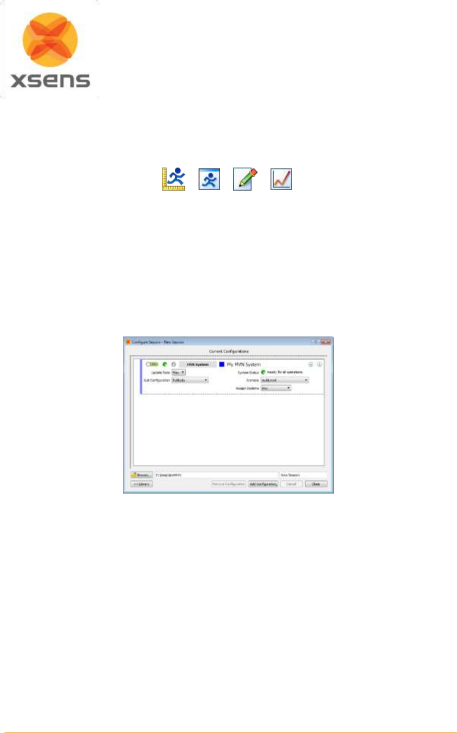
Document MV0319P.N
© Xsens Technologies B.V.
MVN User Manual
31
7 Workflow and Functionalities in MVN Studio
MVN Studio is designed for optimal flow of the steps required for recording and analyzing motion.
Different workflow items become active at various stages.
Figure 23: The workflow toolbar gives the user an optimal interface setup per functionality: Hardware and
Fusion Setup, preview and record, playback and editing and analysis
7.1 New session
A new session is created during the workflow stage “Hardware and Fusion Setup”. Before creating the
new session, ensure that the hardware is connected and powered on.
7.1.1 Create a New Recording Session
To create a new session, click the icon or go to File >Create a new recording session. Figure 24 shows
the first interface to appear.
Figure 24: Configure a new session
Note that all details are default and ready for first time use. For quick start, wait for the status icon to
turn green, click ‘close’ (or ‘apply’ when settings have changed). Now the live, uncalibrated character
will appear on screen. Go to Section 8 for instructions to proceed.
For a more informed, step-wise approach, it is useful to read the following steps for guidance.
7.1.2 New Session, step-wise
7.1.2.1 Add Configuration
Using the ‘Add Configuration’, button a number of configurations can be selected from a drop down
menu, including:
MVN systems, see 7.2
The Video Camera, see 7.3
Define X-Axis, see 7.4
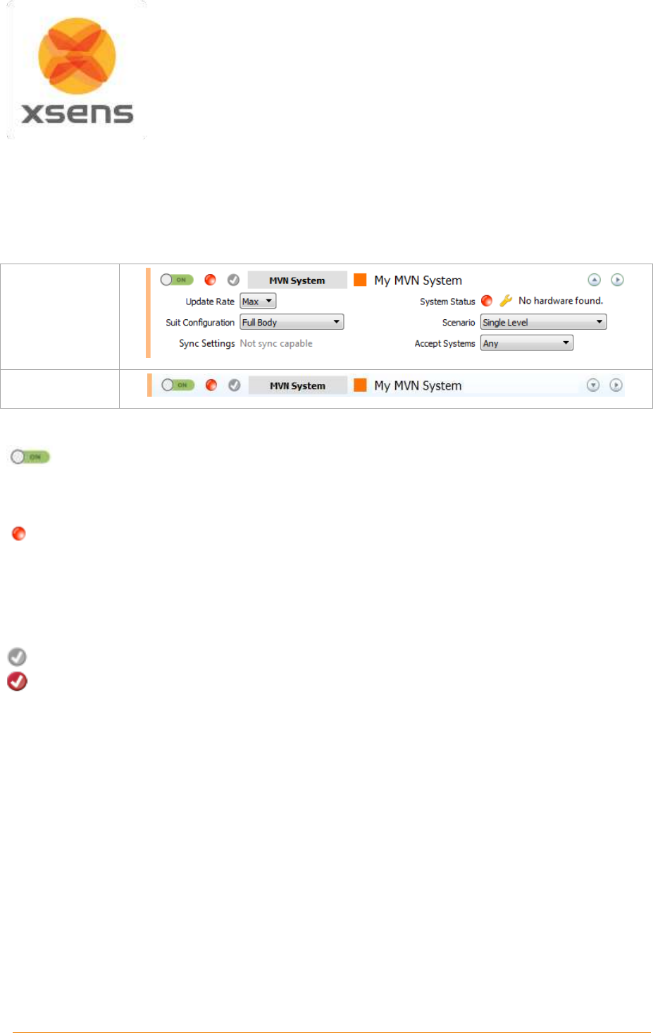
Document MV0319P.N
© Xsens Technologies B.V.
MVN User Manual
32
Sync Station, see 7.5
Configuration Group, see 7.6
7.2 Configure an MVN System
When the user has clicked “Add Configuration” and selected “MVN System” the following configuration
window will appear. The image below shows the expanded and views and details how to modify the
settings. Note that the Sync Settings dialogue is available only with an MVN BIOMECH license.
Expanded view
Collapsed view
7.2.1 Enable/disable search for new system
As described above, click the button on the top left corner from OFF (red) to ON (green). While
the default settings are enough to proceed with a single suit, additional changes can be made.
7.2.2 System Status
The system status appears in the top row as an icon, so that in both the expanded and collapsed
views it is possible to identify the status of a given item. In accordance with traffic-light indicators, green
indicates that everything is in order, while red indicates that there is a problem to be addressed. In the
expanded view, the text accompanying the colored icon specifies the problem and clicking the spanner
opens the hardware status window for detailed trouble shooting.
7.2.3 Apply Changes
Grey: no applied changes
Red: unapplied changes
Changes can be applied by clicking on the grey icon or by clicking on the ‘apply’ button which will also
close the dialog.
7.2.4 Configured Item
This simply gives the name of the item being configured, e.g. an MVN System, Video Camera, Define
X-Axis and Sync Station. This is read-only text.
7.2.5 Suit Color
Particularly useful when measuring multiple systems, it is possible to change the color of the suit, by
clicking the colored square next to the configuration name. The system configured in the example
session dialogue above is orange. It is replicated as read-only color on the left-hand bar, to facilitate
easy identification, also in the collapsed view.
7.2.6 System Name
It is advised to change the name of the system from “My MVN System” to a more personalized name,
for example the name or ID of the person wearing the system. (It can also be deleted if not needed.)
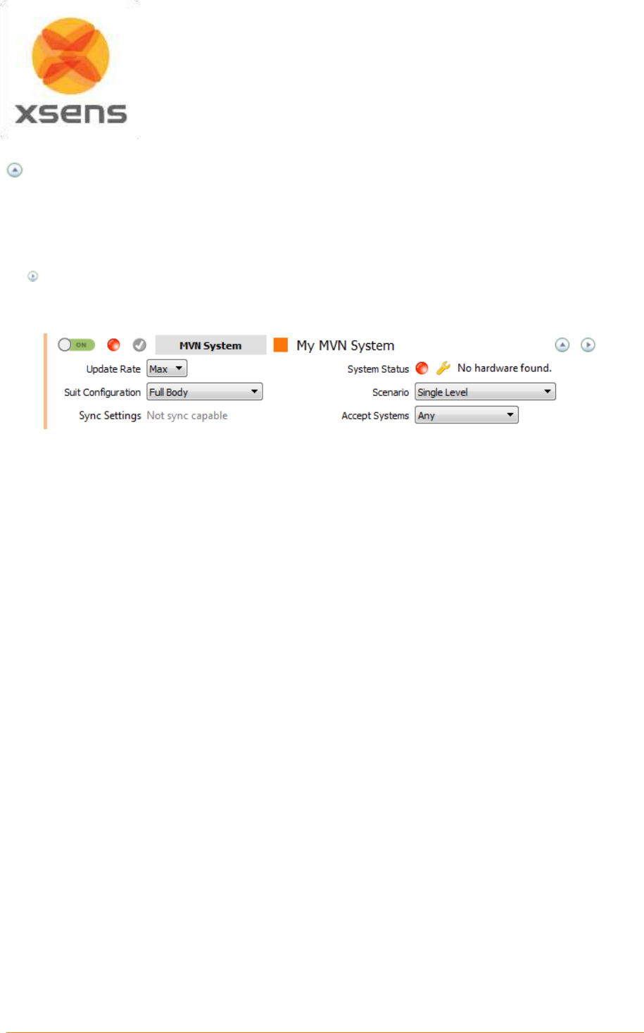
Document MV0319P.N
© Xsens Technologies B.V.
MVN User Manual
33
7.2.7 Expanding and Collapsing Views
On first use, one system is detected and the expanded view is enabled. It is possible (likely) that
after a number of times using the system, or if many configured items are in the list this detail is no
longer required. For this reason it is possible to still have an overview of the system status in a more
compact view.
7.2.8 View Hardware Status
For MVN Link this view is only needed for troubleshooting or relocating trackers. For MVN
Awinda, it may be necessary to change the radio channel, which is possible in the hardware
status window. See Section 7.8 for detailed information.
7.2.9 Update Rate
Default and maximum sample rate for MVN-link is 240Hz, this is normal for single-subject capture with
PC all requirements met. When only one system is in use, it is common to use this update rate. With
multi-person capture, or in situations with extremely adverse conditions for the wireless link, consider
reducing the update rate to reduce the amount of data needed to be transmitted and processed.
The maximum update rate for MVN Awinda Full Body is 60Hz. This update rate ensures retransmissions
of possible lost data packets can be sent to the system. For more information about update rates versus
sample frequencies, please see Section 19.9.
7.2.10 System Status
For both MVN Link and MVN Awinda, this indicator represents the status of the system being connected.
The color of the indicator will change from red to green when a system is successfully connected. For
detailed information see Section 7.8.
7.2.11 Suit Configuration
When a connection between the PC and the live system is made, a detection phase takes place within
MVN Studio to detect all necessary hardware. To ensure that MVN Studio searches for the correct
hardware, ensure that the correct suit configuration is chosen. If for example full body is selected, when
no hands are connected, this will result in an error when the suit is detected.
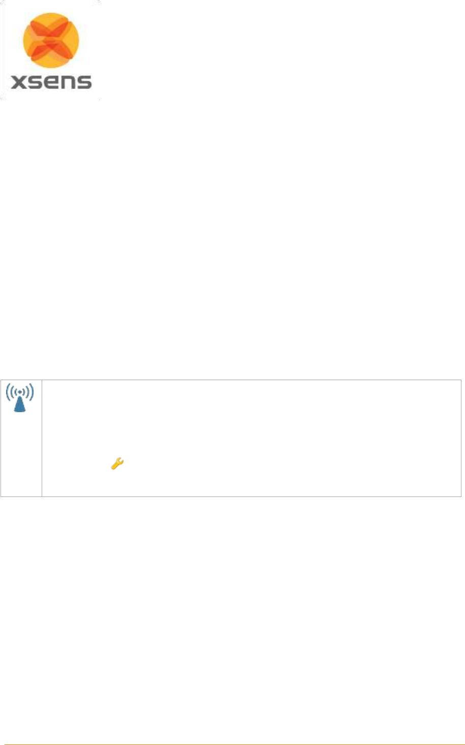
Document MV0319P.N
© Xsens Technologies B.V.
MVN User Manual
34
7.2.12 Scenario
Depending on the type of measurement you will carry out, select the type of scenario that will ensure
the best results, and minimize post-processing. The scenarios available include:
Single Level
This scenario assumes that the subject will be walking on level terrain
Multi Level
This scenario assumes that the subject will be walking on terrain or varying height,
e.g. climbing stairs.
Pelvis Fixed
This scenario assumes that the subject will remain in a seated position, e.g. in a
car. This means that the pelvis will remain at a preset height. Small amount of
motion of the pelvis is accepted.
Pelvis Fixed
Tight
This scenario assumes that the subject will remain in a seated position, e.g. in a
car. This means that the pelvis will remain at a preset height. No motion of the pelvis
is accepted.
Soft Floor
This scenario is used if it can be assumed that the feet will slightly decrease in
height, during the time between the feet contacting the ground and leaving it, e.g.
grass, or soft carpet.
7.2.13 Accept Systems
From this drop-down menu, select the type of hardware connected to MVN Studio. This is set to “Any”
as default, making it easy if only one system is connected. It is also possible to specify MVN Link or
MVN Awinda.
7.2.14 Sync Settings
With MVN Awinda, the dialogue to configure the sync settings is in the MVN System configuration.
To configure the Sync Station which is the method for synchronizing MVN BIOMECH Link with third
party devices, the sync settings are configured via “Insert configuration” “Sync Station”.
It is worth noting that sync with MVN Awinda is tighter than with MVN Link due to the tight control
of the Awinda Station over the MVN Awinda System.
Click the icon: to configure the sync settings.
For detailed information regarding sync settings, refer to section 23.
7.3 Configuring the Video Camera
If a video camera is to be used, select “Video Camera” from the “Add Configuration” list. Note that before
this can be configured, The MVN reference camera, must be plugged into the mains power supply and
to the network connector of the pc or laptop in use. MVN Studio should automatically detect the camera
(if not, use the command “Scan for cameras”). If using a MVN (BIOMECH) Link system, connect the
camera Ethernet cable into the Access Point and connect the AP directly to the Computer via Ethernet.
7.3.1 Configuration
Changing the video configuration is effectively changing the frame rate.
MVN Studio supports VGA, video data will always be in color, with a resolution of 640 x 480.
To avoid flickering due to artificial lighting related to the mains frequency (50 Hz in Europe, 60 Hz in
USA), select the appropriate frame rate (25 or 50 fps for Europe or 30 or 60 fps for USA).
Note that unless using a high performance computer with a fast HDD, it is advised that a lower frame
rate is chosen (25 or 30 fps).
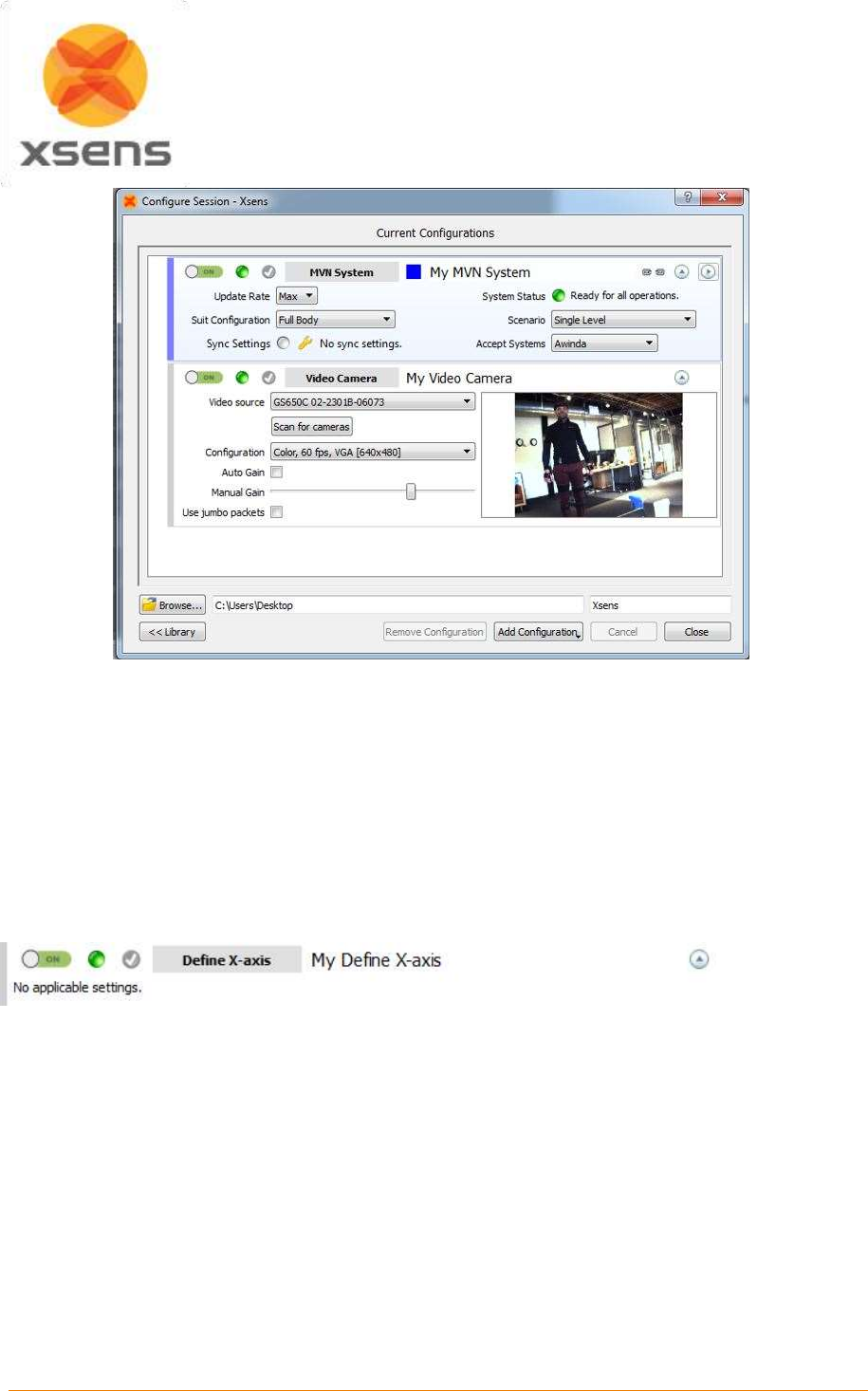
Document MV0319P.N
© Xsens Technologies B.V.
MVN User Manual
35
Figure 25: Example of camera configuration window
If no pictured is displayed, if the image is jagged, or no camera is found, install the dedicated driver,
found in C:\Program Files\Allied Vision Technologies. You may have to restart MVN Studio for the
camera to be found after this is installed. If no video data is displayed, check or uncheck the Use jumbo
packets option to resolve the issue. The camera needs be connected to the dedicated ethernet port on
the pc, whereas the internet connection can use the USB to Ethernet adapter.
You may select to check the Auto Gain box or manually adjust the gain of the video yourself in this
window.
7.4 Define X-Axis
MVN Studio uses magnetic north as positive X-axis, inserting this configuration means that it is possible
to define the X-axis, an additional calibration step will be needed, in which the direction the subject is
facing defines the new X-axis. In a setup with multiple MVN systems, the first system in the list of the
‘Setup pane’ needs to perform the calibration.
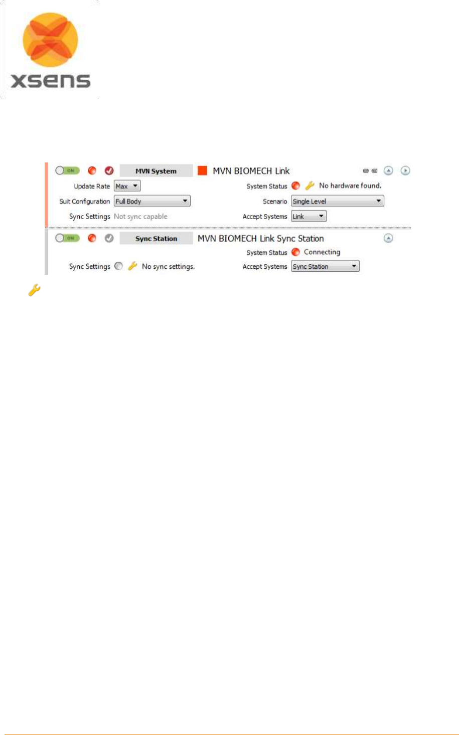
Document MV0319P.N
© Xsens Technologies B.V.
MVN User Manual
36
7.5 Configuring the Sync Station
The Sync Station is dedicated hardware for synchronizing between MVN BIOMECH Link and third party
systems. The user will note that when MVN BIOMECH Link is selected, the text beside Sync Settings
states “Not sync capable”. The Sync Station must be inserted for synchronization with MVN BIOMECH
Link.
Click to configure the sync settings. For details about each setting, refer to Section 23.
7.6 Configuration Group
It can be expected that there are multiple users of a given MVN system, or that certain users have a
certain set up that is always in use. In this case, it is possible to group a set of configurations into group
configuration. This can be done in a number of ways:
1. Once all configurations are in the list; select them, then right click and select “Group”.
2. Right click on the first MVN System and select ‘Group’. This configuration will then be collapsed into
a Configuration Group labeled ‘New Group’. Click and drag remaining items into the group.
It is advised to rename the group from “My Configuration Group” to match the group contents. By
toggling the Enable button from ‘Off’ to ‘On’ for the Configuration Group, all items in the Group will also
be enabled.
7.7 Loading configurations using the Library Button
To save configurations (grouped or otherwise), open the Library pane by clicking on the icon “>>Library”,
then click and drag the items into the Library.
To retrieve a saved configuration, click and drag the items (or group) from the library into the Current
Configuration window.
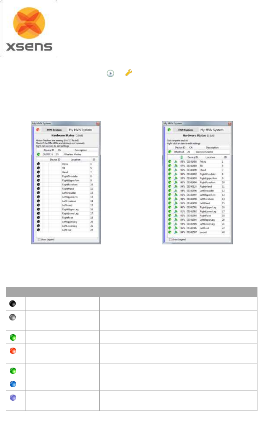
Document MV0319P.N
© Xsens Technologies B.V.
MVN User Manual
37
7.8 Hardware Status
To view the Hardware Status, Select the or in the configuration window.
Hardware status shows a list of all trackers and masters detected by MVN Studio. The figures below
show the hardware status interface and Table 3 details the meaning of the colored markers. This menu
can be edited while the Configure Session window is also open, instructions for editing can be found
below. When the Configure Session is not open, this interface is read-only.
Figure 26 Hardware Status before a wireless
connection has been established
Figure 27 Hardware Status network connection is
established and ready to measure
Table 3: Legend of colored markers in detected hardware screen
Icon
Legend message
Description
Not detected
Motion tracker of a given segment is not detected
Tracker Rejected
When a tracker is double click, indicating it is not needed,
it is known as “rejected”. Its icon becomes grey.
Tracker Connected (MTw)
Motion tracker is connected to the master
Master detected
Network not locked
Wireless master is detected. Red icon has not been
double clicked to secure the network.
Connected (Master)
Green icon at the master indicates network is secured.
MT unused
An extra motion tracker has been detected
Duplicate
More than one motion tracker has been detected with the
same location ID.
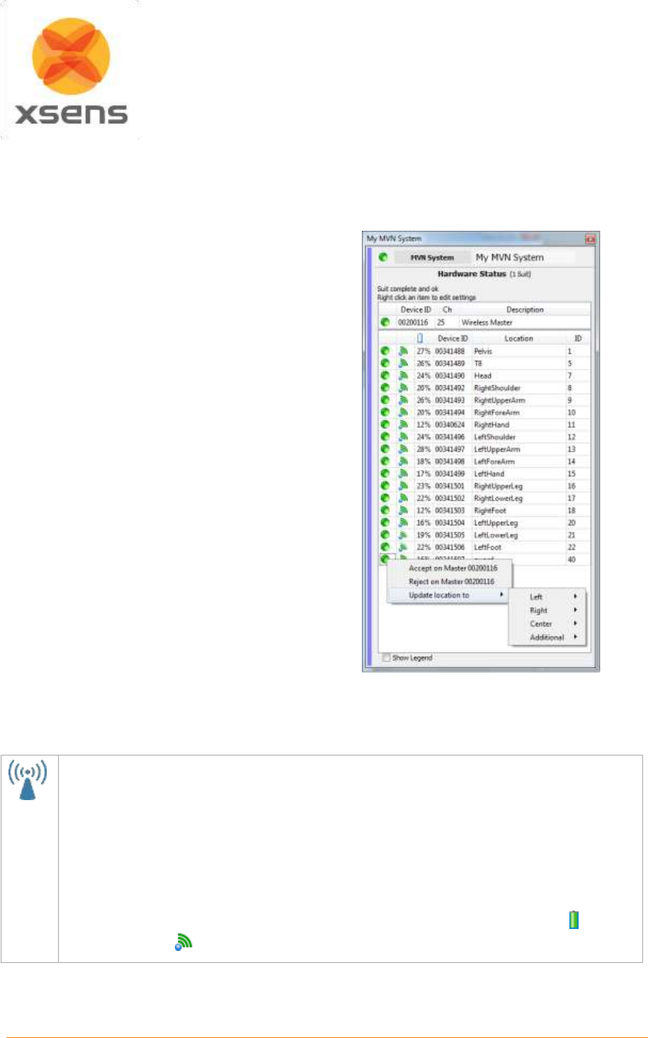
Document MV0319P.N
© Xsens Technologies B.V.
MVN User Manual
38
When all trackers have been detected, it may take some time (up to 30 seconds) to secure the network
and for the 3D character to appear. Additionally, it may take several seconds for the battery status to
display, please be patient to allow the information from each tracker to be transmitted to MVN Studio.
7.8.1 Relocating motion trackers
Each Xsens motion tracker has a unique location
ID which relates them to the limb segment they
should be placed on. If for some reason, a tracker
has the wrong ID assigned to it, e.g. if an
additional motion tracker is detected or a broken
MT needs to be replaced with a spare, this can
be done easily by reassigning the MT’s ID to the
desired position.
To assign a tracker to a different segment, drag
and drop the ID to the Location, or vice versa.
Alternatively, right click in the correct row and
select “Update location to”. To ensure that the
changes are saved, go to >Tasks >Reinitialize
suit(s).
Note that if two motion trackers are accidentally
exchanged, for example on the hands or feet, do
not use this function but reconnect the MT’s to the
appropriate side and wait for the hardware status
to update.
Figure 28 Relocating trackers
7.8.2 MVN Awinda: Changing Radio Channel
For MVN Awinda users, the Hardware Status is necessary in order to configure the network
detection status of the system.
Figure 26 Shows a list of motion trackers expected to be found by the MVN Awinda system. The
icons of these trackers are black indicating that they are expected but not yet detected. As the
Awinda Station is searching for MTw’s, the CONN LED of the Awinda Station, or the white LED of
the Awinda USB dongle blinks rapidly. As each MTw connects, its LED will blink synchronously with
that of the Awinda Station and its indicator will turn green in the Hardware Status window, see
Figure 27.
When the trackers has been detected, the status of the remaining battery power ( ) and the
wireless strength ( ) of each tracker is available, see Figure 27 for an example.
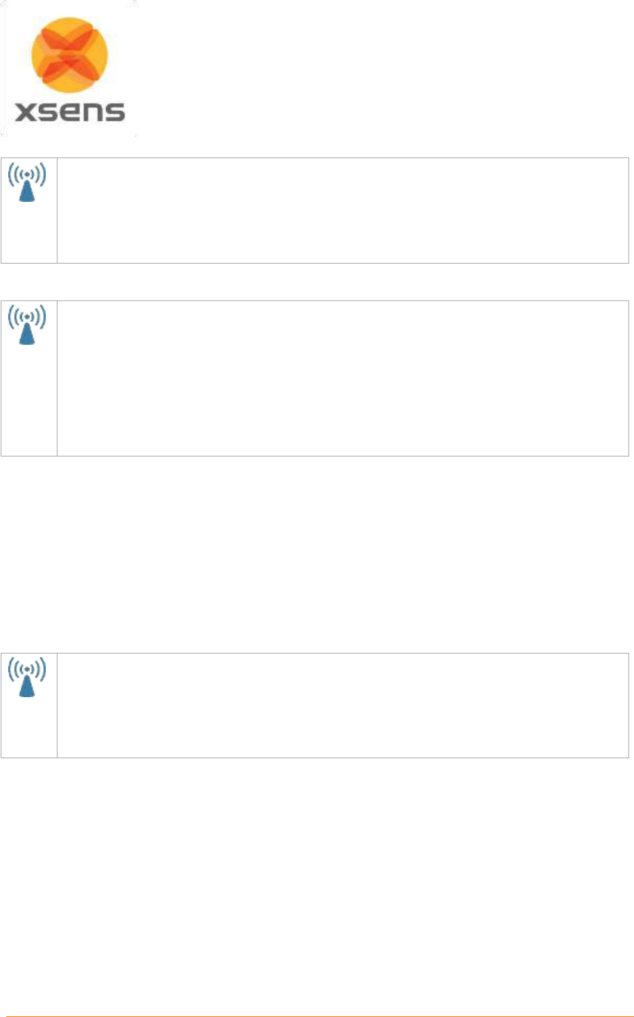
Document MV0319P.N
© Xsens Technologies B.V.
MVN User Manual
39
7.8.3 MVN Awinda: Changing Radio Channel
In the Hardware Status window, either right click or double click the number under the letters “Ch”.
A small menu appears providing the option to change radio channel, reject unused trackers or
“forget” system.
In general, when working in an environment known to have a lot of WiFi traffic, it is best to select
channel 11, 15, 20 or 25. See Section 19.12.1 for background information.
7.8.4 MVN Awinda: Reject Unused Trackers
Again, in the Hardware Status window, either right click or double click the number under the letters
“Ch”.
From the small menu it is possible to reject unused trackers. It is possible that the MTw is powered
on, but not needed for a particular session. This is particularly useful for owners of multiple Awinda
Systems where an MTw is detected by one Awinda Station but is needed at another. To remove
detected trackers, either select the “reject unused trackers” or double click anywhere on the row
the tracker appears in and select “Reject on Master ********”. If this was done accidentally of you
want to accept a new tracker, simply double click again and select “Accept on Master ********”.
7.8.5 MVN Awinda: Forget System
To explain the use of the command forget system it is first useful to understand how MVN Studio deals
with connection. For single person capture, the information in the hardware status window tends to
always be the same tracker/master information. However it may change depending on: different suit
configurations and whether or not props are used. Additionally, some institutes may have multiple suits
within radio contact of each other, each measuring one subject. For this latter usage and for the purpose
of multi-person capture (multiple suits connecting to one MVN Studio instance), MVN Studio actively
remembers which motion trackers have connected to which master (Awinda Station or Body Pack). The
result is that when the user attempts to connect the trackers to the same master at a later time, MVN
studio only allows the remembered trackers to connect. This ensures efficient connections for always
using the same suit configuration and prevents unwanted connections between masters and trackers.
Again, in the Hardware Status window, either right click or double click the number under the letters
“Ch”.
If a user attempts to make a connection in an existing configuration between an Awinda Station and
a tracker used for the first time the option “Forget System” should first be selected. After this
command, all trackers (including previously rejected ones) can connect again.
When all devices necessary for the suit configuration are detected, the 3D character will appear in the
3D viewport.
Ensure that the filename and directory are correct; then click apply to proceed. See section 8.
7.9 Props
In addition to the normal suit configuration, additional MT’s can be attached to items to be measured in
a recording, for example a sword, or a walking stick. These items to be measured are called “Props”
and the motion tracker (MTw or MTx) attached to them are “Prop Trackers”. A prop can be tracked by
attaching a prop sensor to one of the free connectors on the hands.
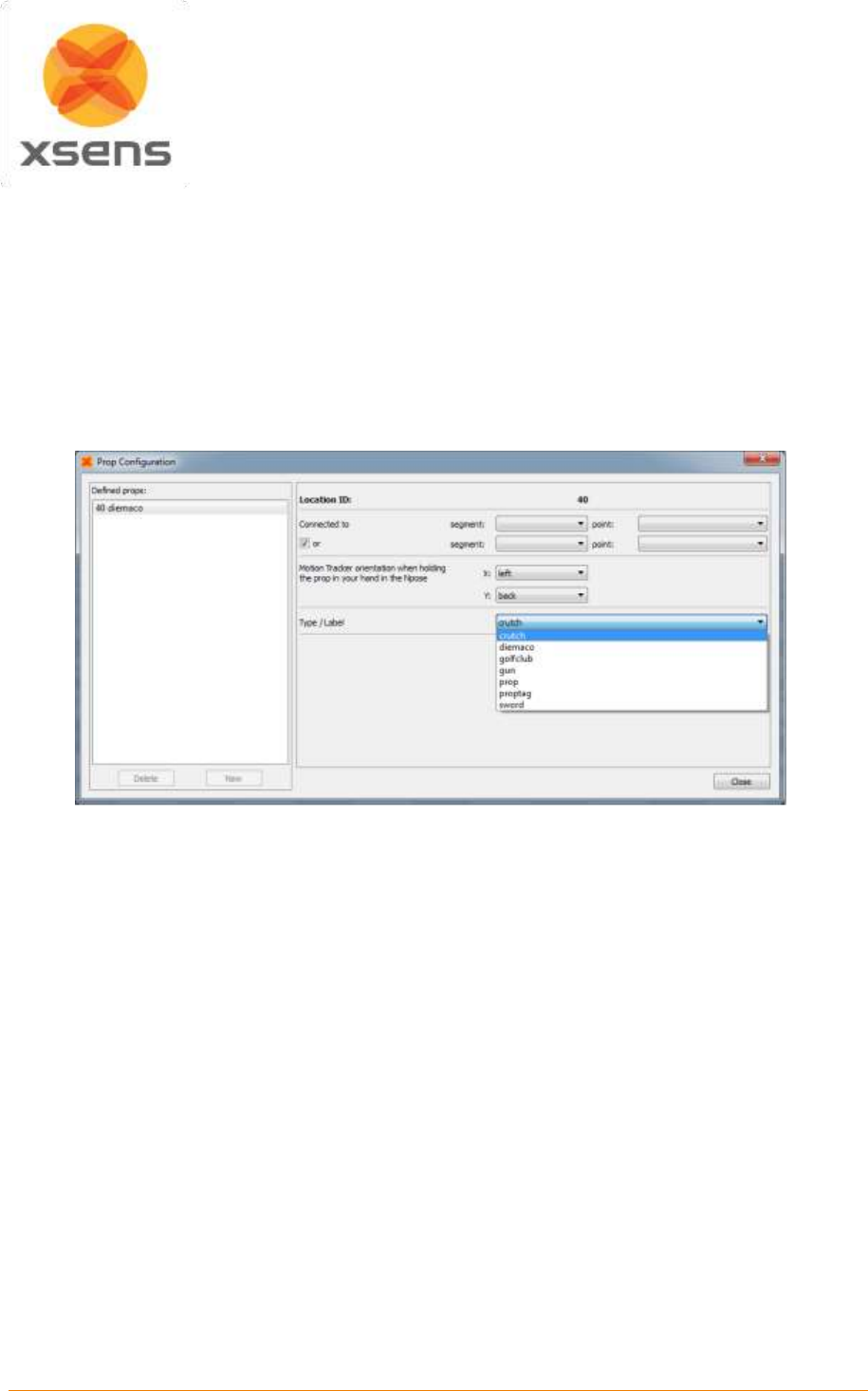
Document MV0319P.N
© Xsens Technologies B.V.
MVN User Manual
40
The prop tracker must be configured in the menu Options >Configure Props. Here, the type of prop can
be selected (crutch, sword, gun, diemaco, golf club, prop [this is simply a right-handed axis]), which can
be assigned to a given suit and a given motion tracker ID.
Generally the motion tracker on the prop is detected automatically when clicking ‘Apply’ in the Prop
Configuration window. If this does not occur, go to Tasks >Re-initialize suit(s). The prop mesh (the on-
screen image of the prop sensor) can be connected to any defined point on a body segment. The prop
can be rotated freely but will always follow the position of the selected point. By selecting the ‘or’ option,
the prop tracker can be swapped between two segments, for example the right and left hand (see the
example in Figure 29). MVN Studio will automatically detect the side on which the motion tracker is
connected.
Figure 29: Prop configuration menu
For example, when holding a sword, the blade may point forwards. When holding a gun, the barrel will
point downwards. Look at the X, Y arrows as indicated in the images below.
The prop tracker should be mounted onto the prop such that two sides of the casing are parallel with
the prop. For example, mount the prop tracker on the flat side of a sword with one axis aligned with the
blade of the sword. Then, the orientation of the motion tracker can be set according to the natural
orientation of the physical prop when holding it while in an N-pose.
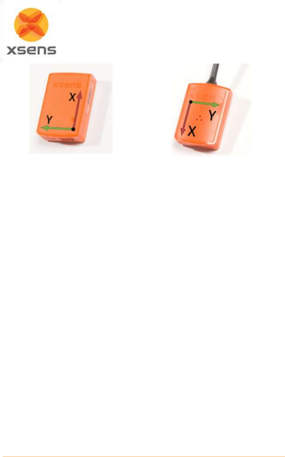
Document MV0319P.N
© Xsens Technologies B.V.
MVN User Manual
41
MTw
MTx
7.10 Navigator
When a new session has been created, suit-specific variables can be viewed in the navigator. This
generally appears automatically on the left side of the window. If not, it can be found using
View >Navigator. In the navigator, parameters of the suit can be seen, including the Suit ID and the
color of the indicator above the head of the 3D character. While this is possible with only one system, it
becomes essential when multiple systems are being recorded at once.
If recording of multiple suits has been chosen during the new recording session, MVN Studio will search
for the selected number of systems. If more than one system is connected, the hardware status will have
additional tabs to reflect this.
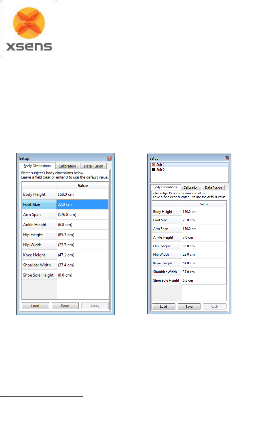
Document MV0319P.N
© Xsens Technologies B.V.
MVN User Manual
42
8 Setup
The setup workflow stage consists of three parts; input the subject’s body dimensions, data fusion and
sensor to segment calibration. The calibration procedures are only available once the MVN system is
connected and the 3D Character has appeared in the view port.
When a file has been recorded this icon remains active to enable changes to body dimension inputs.
NOTE: It is not possible to save a calibration file, when a recorded file is open.
The following steps are described for single system calibration. If multi-person capture is enabled, each
step should be repeated for each additional system.
8.1 Body Dimensions
A)
B)
Figure 30: Input body Dimensions of test subject. A) Single subject capture B) Two subject capture
Figure 30 shows the interface for inputting the subject dimensions prior to a sensor to segment
calibration. It is necessary to input body height and foot length (shoe length at the time of the
measurement) in order for MVN Studio to calculate other segment lengths (based on an anthropometric
model). A recording cannot be performed if the user does not insert these values; instead the
following error is generated:
5
5
Note that a recording can be performed without prior insertion of body dimension and without a calibration, if the
feature “Allow uncalibrated recording” is enabled in the preferences menu.
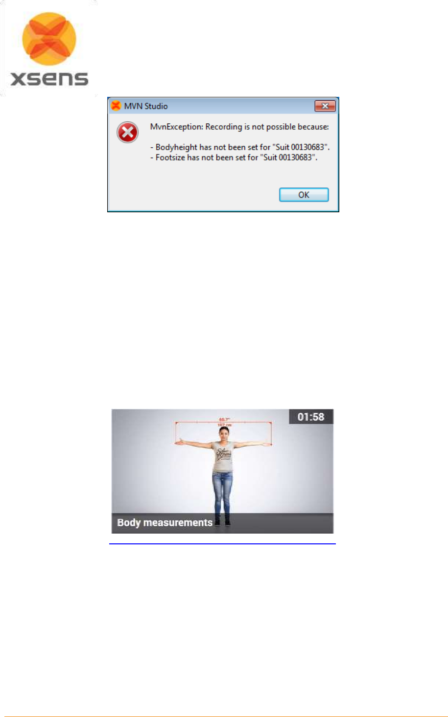
Document MV0319P.N
© Xsens Technologies B.V.
MVN User Manual
43
Figure 31: Error generated if recording attempted without subject height and foot length.
In addition to these basic measurements, other body segment dimensions can be adjusted for subject-
specific anthropometry. The model-based values are presented between brackets, as Figure 30 shows,
e.g. Knee Height (48.6). The scaling model is based on the height of the subject without shoes. The
shoe sole height can be added as an offset to the feet. The height of the ankle joint will be adjusted
internally and other segment dimensions, such as the leg length, will not change. If the subject and ankle
height are measured with shoes on, all segment lengths will be scaled based on this length and the
shoe sole thickness should not be entered. However, for improved accuracy, it is advised to measure
height without shoes and insert the shoe height separately.
It is possible to provide values in either metric or imperial units. Metric units are active by default. To
switch to imperial units go to: Options >Preferences >Interface >User interface >‘Use imperial units
(inches)’.
The specific body segment dimensions are presented in Table 4. They can be found by palpating the
anatomical landmarks, presented in the figures on the next page and in the online video tutorials:
https://tutorial.xsens.com/video/body-measurements
Be careful! If you are not sure how to accurately measure the dimensions, do not change the default
values; the calculated values are generally accurate enough.
To scale the model with these dimensions, click ‘Apply’. The system will automatically update
dimensions for which no user input is provided.
The subject body dimensions can be saved to your computer as an MVN Actor (.MVNA) file which then
can be loaded the next time the same subject is used. After loading a subject file, it is still necessary to
perform a segment calibration. It is also possible to modify body dimensions and reprocess the file with
the new settings.

Document MV0319P.N
© Xsens Technologies B.V.
MVN User Manual
44
8.1.1 Offline Body Dimensions
In order to facilitate data collections, body dimensions can be measured and input into MVN Studio
without connecting an MVN suit through the ‘Offline Body Dimensions’. This feature allows users to
save body dimensions as an MVNA file prior to instrumenting a subject. Later, when the system is
connected, the file can be loaded again from the Body Dimensions panel.
To access the Offline Body Dimensions window, simply go to Options >Preferences >Miscellaneous
>Offline Body Dimensions.
Table 4: Measurements needed for Subject Dimension Input
Dimension
Description
Body height
Ground to top of head when standing upright
Foot size
Top of shoe nose to end of the heel
Arm span
Top of right fingers to top of left fingers in T-pose
Hip height
Ground to most lateral bony prominence of greater trochanter
Knee height
Ground to lateral epicondyle on the femoral bone
Ankle height
Ground to distal tip of lateral malleolus
Hip width
Right to left anterior sup. iliac spine
Shoulder width
Right to left distal tip of acromion (acromial angle)
Shoe sole thickness
Average thickness of the sole of the used shoes.
This value will add an offset to the ankle height.
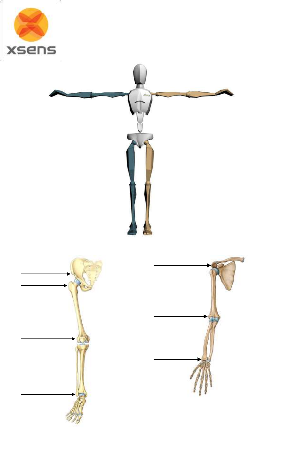
Document MV0319P.N
© Xsens Technologies B.V.
MVN User Manual
45
Figure 32: T-pose with body segment dimensions
Figure 33: Anatomical landmarks on leg (left) and arm (right)
Greater trochanter
Lateral epicondyle
Lateral malleolus
Ant. sup. iliac spine
Lateral epicondyle
Radial styloid
Acromion
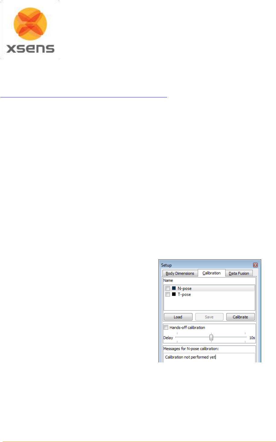
Document MV0319P.N
© Xsens Technologies B.V.
MVN User Manual
46
8.2 Calibration
Segment calibration is the step required to align the motion trackers to the segments of the subject.
Watch the video on the tutorial portal for instructions on how to perform the calibrations:
https://tutorial.xsens.com/video/setup-and-calibration-mvn-link.
Creating a good calibration is of utmost importance in order to ensure accurate results. For this reason,
the calibration procedure should be carried out in a magnetically-sound environment. The “Show
Magnetic Disturbance” is fixed at “Always on” when the calibration tab is active.
It is advised to check the measuring area for magnetic disturbances. To do this, move around the
measurement area. Areas which appear green, particularly on the feet and pelvis are good for the
calibration step. If measurements are needed in areas that reveal red in the magnetic field disturbance,
first calibrate in the “green” areas then move temporarily to the disturbed area. Do not remain there for
longer than approximately 30 seconds.
8.2.1 Calibration steps
Please note that it is always recommended that a calibration is performed before beginning to record
data using MVN Studio. However, it is possible to enable a measurement without calibration in the
preferences menu (Options >Preferences >General >Recordings).
Another option in the preferences menu is “Expert calibration” in this menu. Expert calibration is intended
for users who have been advised by specialists at Xsens to perform a hand-touch calibration in addition
to their N or T pose. However it becomes possible to execute both N and T- Pose by enabling this.
Carrying out both basic poses is strongly dissuaded. If both calibrations are carried out, a weighted
average of both will be used. This is known to lead to inaccuracies in the results.
Select a pose (N or T).
A new image will appear in the 3D viewport
which should be replicated by the subject.
If the subject is alone, first select “Hands off
calibration” and the amount of time needed to
get into position. (See Section 8.2.5)
Click “Calibrate”.
Ensure that the subject is holding the pose.
Click start.
Under Messages for calibration: If the result is
“good”, click “accept”. If “acceptable”, it is the
user’s decision if they wish to improve this. If the
result is “Poor” it is advised that the calibration is
discarded and performed again following the
instructions provided in the Messages area. If
“Fail” results, the calibration must be repeated
before proceeding. (See Section 8.2.6 for more
information.)
Figure 34: Segment calibration interface – new
screenshot with no data fusion tab
Note that if multiple people will be measured simultaneously (multi-person capture), mark a place on the
floor which does not show magnetic disturbances. This will be the origin of the session. Each person
should stand on this spot with the right heel when performing the calibration poses.
The MVN system does not have an absolute positioning system. Therefore, the characters will show
some drift over time in terms of absolute position in space with respect to the origin (defined at
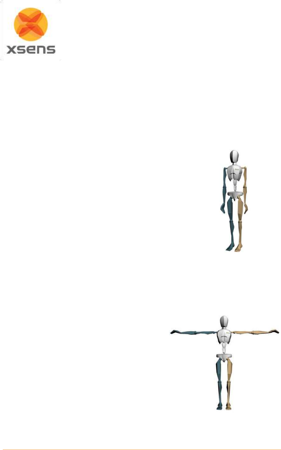
Document MV0319P.N
© Xsens Technologies B.V.
MVN User Manual
47
calibration). For short recordings, the drift of the character is typically limited to a few cm. With multi-
person capture, the characters can drift apart after a while. Usually this can be fixed in the animation
package used for retargeting the motion data to a virtual character.
To reset the position of the characters in between recordings, select the character in the navigator, ask
the subject to return to the marked position on the floor and select menu > Tasks > ‘Move Character to
Origin’ , or press ‘Ctrl-0’ (Ctrl+[Zero Key]).
8.2.2 N-Pose (Neutral pose)
The N-Pose calibration is a basic calibration. It can be performed as a stand-alone calibration or before
the hand-touch. When performing the calibration, take care of the following:
Stand upright on a horizontal surface
Feet parallel, one foot width apart.
Knees above feet.
Hips above knees.
Back straight.
Shoulders above hips; do not pull the shoulders up.
Arm straight alongside body (vertically), thumbs forwards. Check
the correct attitude of the arms by flexing and extending the
elbows. The forearms should move only in the vertical (sagittal)
plane with the palms of the hands facing each other.
Face forward.
Do not move during the calibration procedure.
Following the calibration, if the legs of the 3D character are crossed,
when the feet are together then the feet were too far apart during the
calibration. Repeat the calibration procedure with the feet closer
together for an improved result.
Figure 35: N-Pose
8.2.3 T-pose
The T-pose is the other basic calibration pose. This is recommended if the subject cannot hold the arms
vertically near the body. When performing a calibration, take care of the following:
Stand upright on a horizontal surface.
Feet parallel, one foot width apart.
Knees above feet.
Hips above knees.
Back straight.
Shoulders above hips; do not pull the shoulders up.
Arms extended horizontally, thumbs forwards. Check
the correct attitude of the arms by flexing and extending
the elbows. The forearms should move in the horizontal
(transverse) plane.
Face forward.
Pay attention to symmetry, for example, keep the arms
at an equal height.
Do not overextend the elbow, since flexion/extension
may be projected in other axes.
The wrists, elbows and shoulders should all be on a
single line.
Figure 36: T-pose
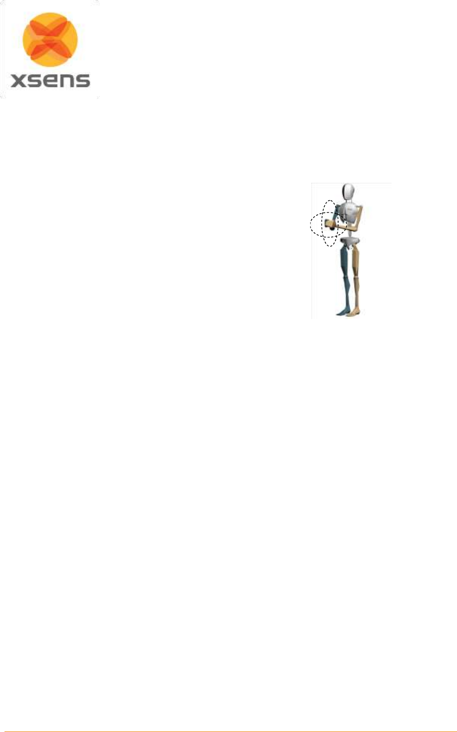
Document MV0319P.N
© Xsens Technologies B.V.
MVN User Manual
48
8.2.4 Expert Calibration: Hand Touch
It is important for the operator to determine if the hand touch is required - in general it is not necessary.
Sometimes it is difficult to get very accurate hand data, even when the N or T pose has been carried out
well. For this reason it is sometimes needed to carry out a Hand Touch calibration. Note that a good N-
pose is necessary to obtain the best results.
When performing the calibration, take care of the
following:
Place the palms of the hands together.
An example of the calibration movement is shown
in the 3D view plane.
Move the hands around slowly while keeping the
hands together
Keep elbows in the same position (10 seconds).
Imitate the 3D character window or perform a
different movement, e.g., making small circles in
all directions.
Figure 37: Hand touch calibration pose
8.2.5 Hands-off calibration
It is possible to perform a calibration without assistance. Click the ‘Hands-off calibration’ check box and
select the delay time. This is the time needed between clicking ‘Start’ and getting into position. Continue
the calibration by clicking the ‘Calibrate’ button. Following the preset time delay, the calibration recording
will automatically begin.
8.2.6 Calibration quality
MVN Studio will perform several checks to determine the quality of the calibration signals. These checks
include: a measure for standing still, the expected alignments of the MT’s on the pelvis and hands, the
homogeneity of the magnetic field, therefore the ability to measure safely in this environment.
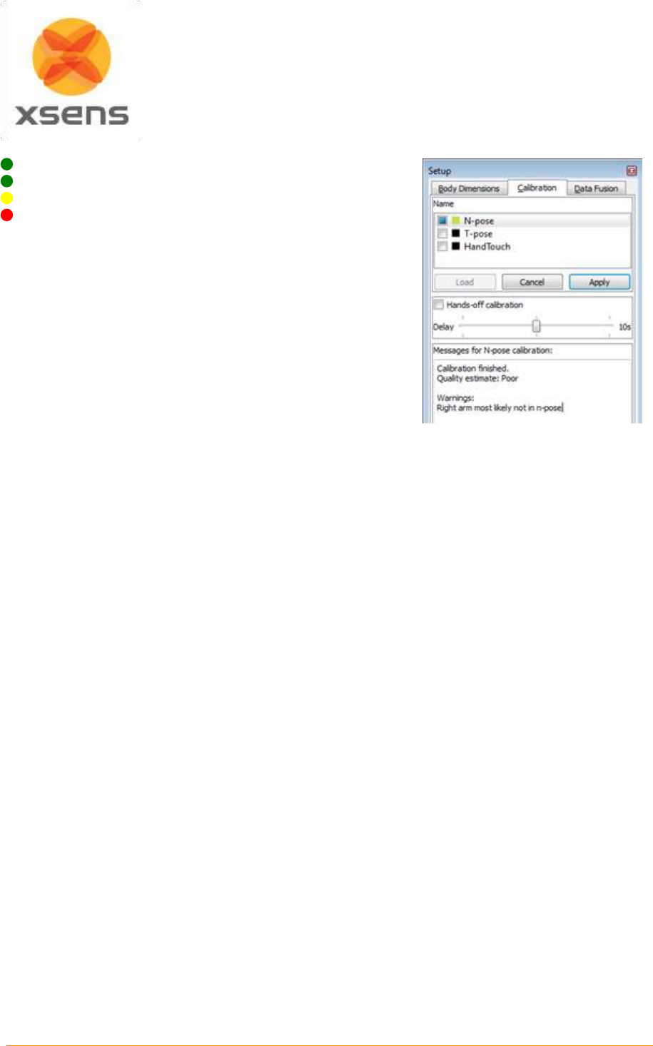
Document MV0319P.N
© Xsens Technologies B.V.
MVN User Manual
49
There are four levels of calibration quality:
good
acceptable
poor
fail
Generally, a ‘good’ or ‘acceptable’ quality indication is sufficient.
If the calibration result is not ‘good’, the reason is indicated in the
text below. Read the advice provided to improve the result. If the
result is “acceptable”, consider repeating.
A ‘poor’ quality indicates that there is too much movement during
the calibration or the magnetic field is disturbed. It is still possible
to continue with recording, but it is better to repeat – taking into
account the advice provided.
Figure 38: Example of result of
calibration quality
Note that a ‘good’ or ‘acceptable’ quality indication does not necessarily mean that the actual calibration
is accurate. MVN Studio can perform limited checks of the actual pose of the subject during the
calibration due to a natural variation in body physique and locations of the motion trackers on the body.
Therefore, always pay attention to the pose of the subject since it will influence the quality of the
recording.
Calibration data can be saved. This is useful if MVN Studio closes/must be closed suddenly. When
rebooting, data can be reloaded, without having to re-calibrate. To reload a calibration (including body
dimensions), click ‘Load’.
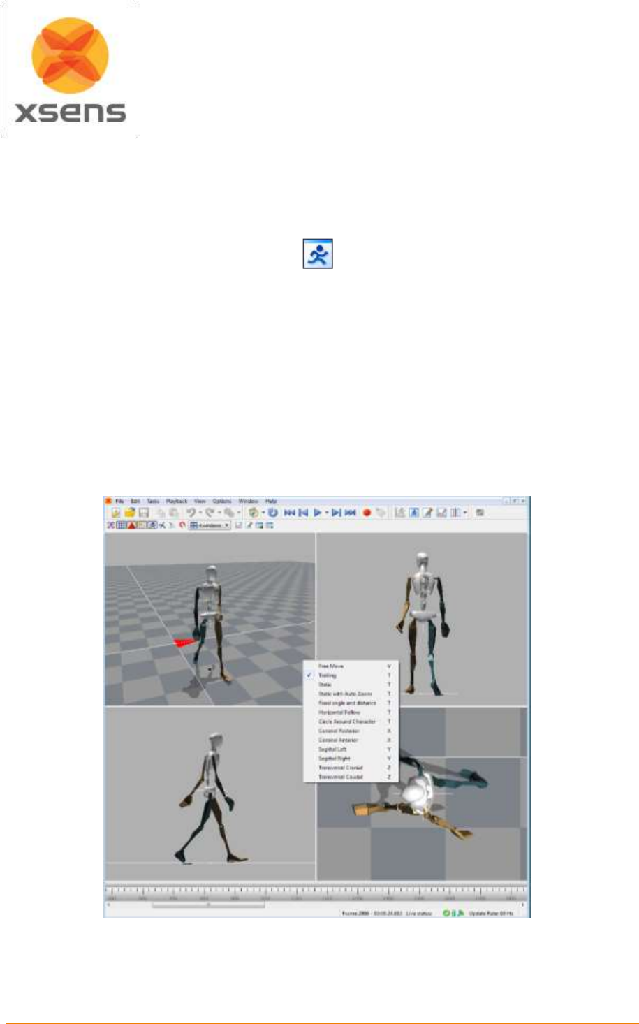
Document MV0319P.N
© Xsens Technologies B.V.
MVN User Manual
50
9 Preview and Recording
9.1 Preview
During the Preview and Recording stage of the workflow, the viewport is active.
There are a number of viewing possibilities, the 3D character in the 3D viewport and orthogonal views.
Select the number of windows to view at one time. Figure 39 is an example of a four window view
showing the 3D view and three different orthogonal views. To select which type to view, Right Click and
select from the drop down menu, as indicated in the figure (or use the shortcut keys). The view changes
only in the window where the cursor is pointing. In the 3D viewport, use the mouse to zoom (using scroll
wheel) and pan (using middle mouse button) around the character. It can be viewed from any angle
(change view using left mouse button) and distance.
With MVN Studio BIOMECH it is also possible to have the synchronized (live) video data. If video is
enabled it automatically uses a window. Note: there is a difference between the virtual camera and the
physical MVN Ethernet Camera. The camera views describe the possible viewing angles of the 3D
character. The only preferences for the MVN Ethernet camera are in Options >Video Camera Settings.
Figure 39: Example of 4 window view on the 3D view port. Top left is the 3D view. Bottom left is sagittal
right. Bottom right is transversal cranial. Top right is coronal posterior.
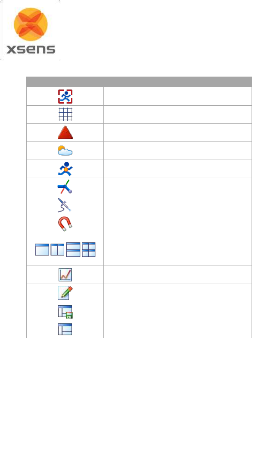
Document MV0319P.N
© Xsens Technologies B.V.
MVN User Manual
51
9.1.1 Viewport Icons
The icons above the viewport can be selected to show and hide various parameters, as detailed below.
Icon
Task
Focus on Selected Segments (short-key ‘F’)
Note: short-key ‘C’ always centers on the pelvis
Show/hide floor
Show/hide origin
Show/hide shadows
Show/hide center of mass
Show/hide biomechanical model
Show/hide motion path (available during playback)
Show/hide magnetic disturbances
Amount and layout of viewports
Show/hide graphs
Enable/disable contact editing in current view
Save Layout
Restore Layout

Document MV0319P.N
© Xsens Technologies B.V.
MVN User Manual
52
9.1.2 Views
Right click on the screen (or use the shortcut key) to choose one of the following camera viewpoints:
Menu command (+shortcut)
Action
Free move (V)
The camera is still.
The character may go out of view of the screen.
Trailing (T)
The character is always in view.
The pitch of the camera is fixed.
The distance of the camera to the character is fixed.
The height of the camera follows the height of the pelvis.
The camera heading is determined from the previous and new character
position.
Static (T)
The position of the camera is fixed.
The camera always looks at the character.
Static with Auto Zoom (T)
Similar principle to “Static” with the addition that the zoom is
automatically adjusted to ensure that the character remains the same
size
Fixed angle and distance (T)
The global heading and pitch of the camera are fixed.
The height of the camera follows the height of the pelvis.
Horizontal Follow (T)
Similar to “Trailing”, but the height and angle of the camera is now
adjusted to prevent the image from varying with change in pelvis height
Circle Around Character (T)
Virtual camera will slowly circle around the centered character
Coronal posterior (X)
Show the back of the character.
Coronal anterior (X)
Show the front of the character
Sagittal right (Y)
Show the right side of the MVN character in the sagittal plane
Sagittal left (Y)
Show the left side of the MVN character in the sagittal plane
Transversal cranial (Z)
Show the top of the MVN character
Transversal caudal (Z)
Show the bottom of the MVN character
The camera angle of the orthogonal views is by default defined by the movement of the pelvis. The
height of the camera is also based on the pelvis; when the character is jumping the character stays
within the view while the floor appears to move. This also has implications in the sagittal view; the subject
may bend, while this appears as though the feet slide forward. The data is still correct (as seen in the
3D view).
9.1.3 Overcoming distortions
Information used to provide the accurate orientations are based on sensor fusion and comes together
in what MVN calls a Fusion Engine. The Xsens Fusion Engine (XFE) uses data collected not only
instantaneously but also built up from the history of the session. If the subject wearing the system
remains in an environment that can be detrimental to the data (e.g. in a prolonged magnetically
disturbing area) it may be necessary to clear the history; this will be apparent by the appearance of the
character, for example segments may be unnaturally twisted with respect to others. Depending on the
severity of the effect of the distortion on the character, two different types of reset are possible as
detailed below.
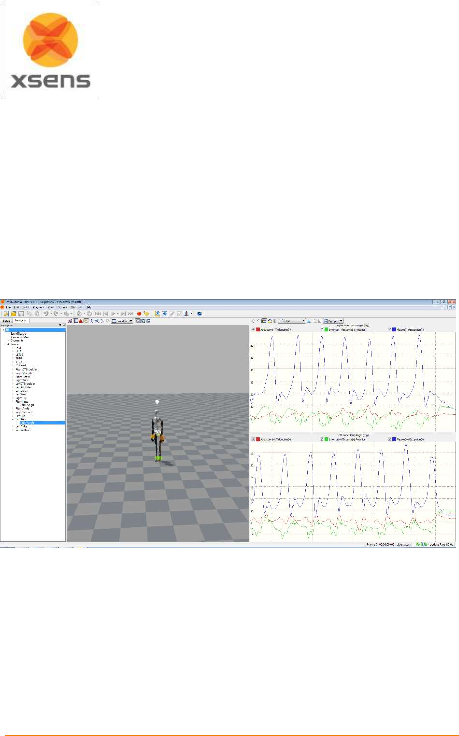
Document MV0319P.N
© Xsens Technologies B.V.
MVN User Manual
53
It is important to note that when a reset is carried out, the subject should stand still in a magnetically
clean environment. Depending on the rest, some time is needed to build up good history again.
Character Reset (menu > Tasks > Character Reset, or Ctrl+Alt+F): This command partially resets the
filters, but keeps valuable information that was stored; the result is that the character will remain in its
horizontal position, and a shorter stabilization period is required (up to 30 s).
Full Reset (menu > Tasks > Full Reset, no shortcut key): This command will completely clear the filters.
This means that all previous knowledge that the system built up will be lost. The character will return to
the origin and a stabilization period is required. This means that the subject should walk around slowly
for about 30 seconds to a minute.
9.1.4 Real-time graphs
With an MVN BIOMECH license it is possible to view graphical representation of data even in real-time
and during recording.
To do this, click the graph icon, and as with offline graphs, click and drag items from the Navigator.
Figure 40: Real-time graphs
Figure 40 is a screenshot of MVN Studio with real-time graphs present. The key difference with this and
the offline graphs is the lack of time bar.
The real-time graphs have the same functionality as offline, for more information on graphs, see
Section 11.1.
Note that it is possible to zoom on the vertical axis. First ensure that “no auto-scaling is selected from
the drop down menu, and then select the magnifying glass icon to zoom. However given that it is not
possible to select a time window over which to observe the real-time graphical data, the recommended
setting during real-time preview is “Expand to fit”, or “Full Fit”.
Document MV0319P.N
© Xsens Technologies B.V.
MVN User Manual
54
9.1.5 Save and Restore Layout
To the right of the graph icon are two icons indicating the possibility to save and restore layouts of the
interface.
To save a layout, use the icon directly to the right of the graph icon, the layout currently in view will be
saved. Give the layout a name, in the drop down menu that appears.
To use a saved layout, click the rightmost icon “Restore Layout” and select the name from the drop
down menu that appears.
It is possible to delete a given layout by selecting it and clicking the delete button on the keyboard.
9.2 Recording
To record, save and export data, first make a new session (as described above) and perform a
calibration.
Record button prior to clicking
Record button during recording6
Press the red record button to start a trial recording. Press the same button to stop recording. The short
key for starting and stopping recording is ‘Ctrl+R’. All recorded and saved files will have the name of the
session, appended with a trial number (e.g. session = ’running_take’ will result in trial recordings
‘running_take-001.mvn’, ‘running_take-002.mvn’ etc.). When a recording has been made, the recorded
file automatically opens. This can be disabled in Options >Preferences >General >Recordings
>Automatically open MVN file after record ends.
9.2.1 Note for recording for MVN Awinda Users
When a recording is initialized in MVN Studio for MVN Awinda, the “Data” LED of the Awinda Station
becomes red, to indicate recording is in progress. Note that if data packets have been missed, retransmission
slots ensure that the Awinda Station can recall these and they can be retransmitted during recording
(retransmissions are activated only during recording).
When recording is stopped, the “Data” LED may become temporarily orange, and the record button in MVN
Studio will temporarily appear as if the recording is paused, the missed data packs are being flushed.
Note: This implies further that if the character does appear incorrect at another time, it is advised to carry out a
reset (as described in Section 9.1.3) to correct this.
When opening a recorded file with flushed data it will automatically start reprocessing. This will ensure that the
file contains all data, including retransmitted data from during the recording and data that was flushed from the
buffer of the MTw at the end of the recording. For this reason, the recorded data is often of better quality than
the real-time preview.
6
With MVN Awinda this button will continue even for a few seconds after recording is stopped, at this time, any
samples missed during real-time recording are being flushed to the PC.
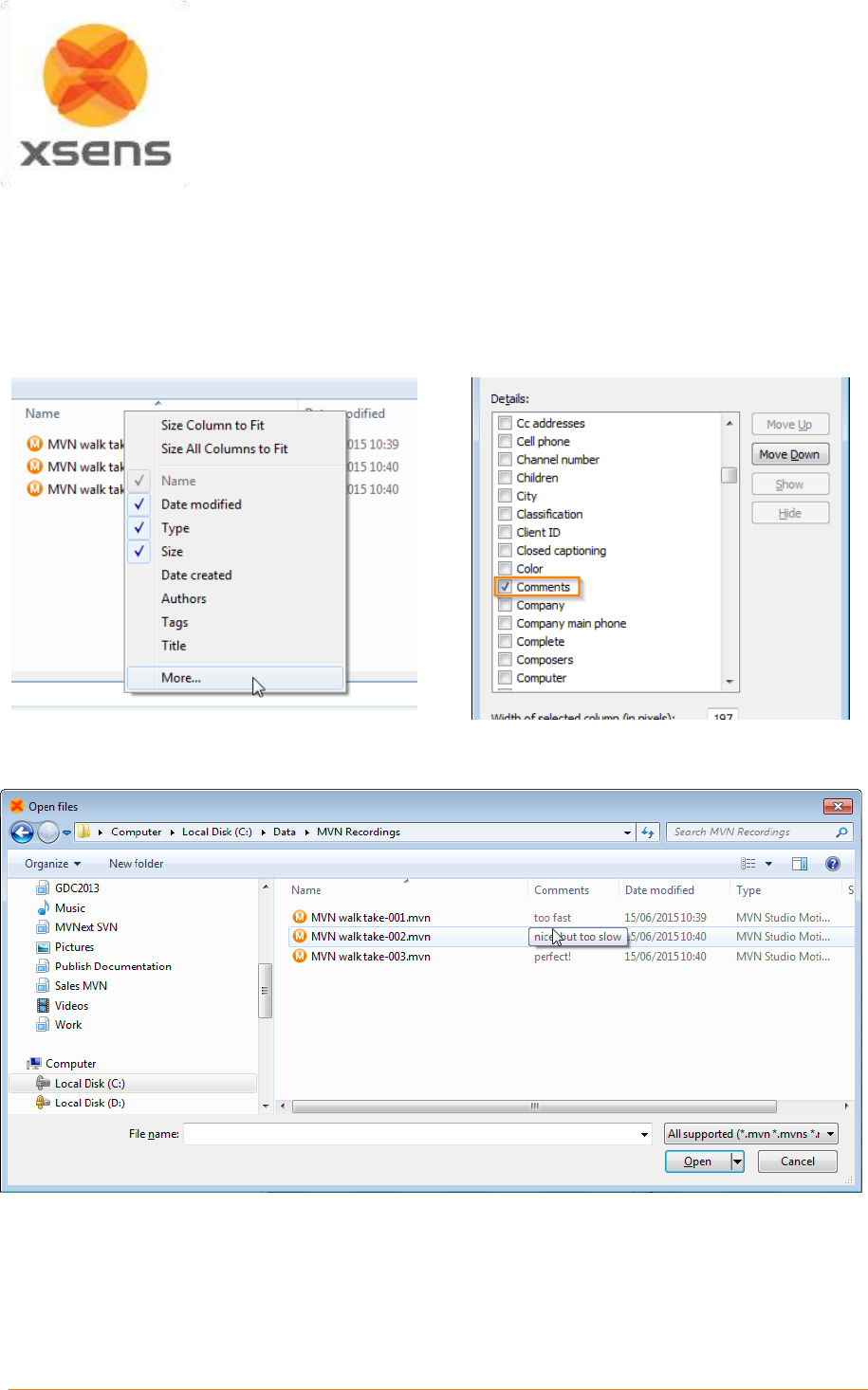
Document MV0319P.N
© Xsens Technologies B.V.
MVN User Manual
55
9.3 Add comments after recording
Adding comments after a recording has finished can be very useful in a later stage when you are opening
the recordings. The popup dialog to add comments after a recording can be enabled or disabled (menu
> Preferences > Interface > User Interface Show popup dialog for file comments after recording).
To view the comments from the open file dialog in MVN Studio or Windows Explorer, you will have to
add the ‘comments’ column. Right click on the column header and click on ‘more’, now you can check
the ‘comments’ column.
Now when you are looking for that recording that was ‘perfect’ you will be able to easily find it from either
the open file dialog in MVN Studio or Window Explorer. When the comment contains a lot of text and is
not fully visible you can hoover over the text and a tooltip will display the complete text.
The comments in recordings can be edited in MVN Studio from the Comments pane (menu > View >
Comments).
9.4 Recovery of MVN file after system crash
If MVN Studio was shut-down as a result of a system crash, the MVN file will not be properly closed and
not useable. To correct this, when you try to load the corrupted MVN file in MVN Studio it will look for a
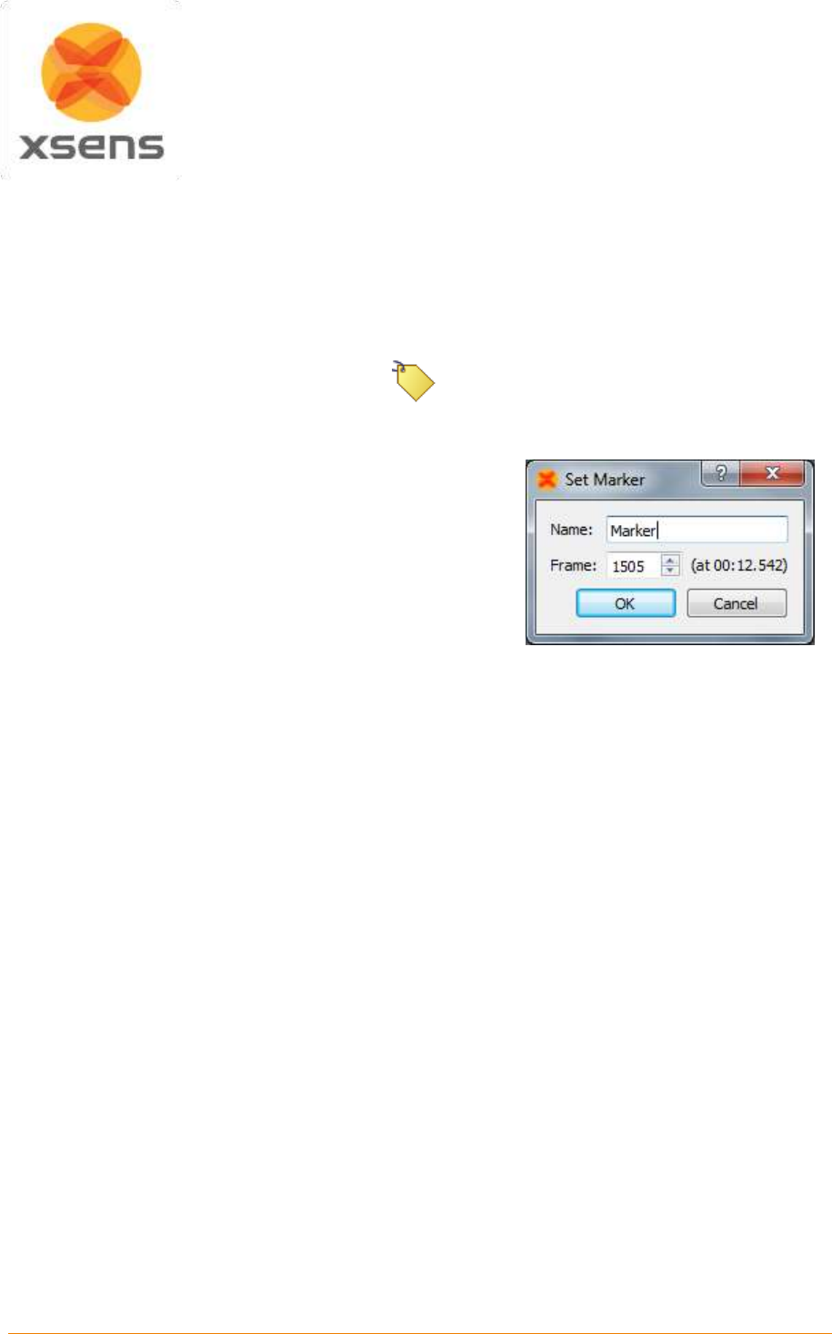
Document MV0319P.N
© Xsens Technologies B.V.
MVN User Manual
56
recovery file (MVR) that can be used to recover the data captured. A message will ask if you want to
use a recovery file. This file has the same name and location as the corresponding MVN file but with a
“MVR” extension. The file is used by MVN Studio to recover the corrupted MVN file.
9.5 Markers
During or after recording, markers can be added to the timeline to indicate events. During recording,
add a marker by clicking the Add Marker icon or by using the ‘+’ key or ‘space bar’.
Add Marker
In the playback window, a marker can be added and/or edited
by double-clicking the timeline at a specific frame or by using
the ‘+’ key. To add a marker directly, in the playback mode,
double click on a time frame, to obtain the “Set Marker” menu
shown in Figure 41. Alternatively, right click above the time
frame, select “Add marker” and the same “Set Marker” menu
will appear. Change the name of the marker in this menu to
identify the marked event.
When the marker is set, it will become yellow. Markers can be
deleted by pressing the delete button after selecting the
marker, or selecting delete marker when right-clicking above
the time line.
Figure 41: Set Marker Menu
Markers are saved as default to MVNX file. See Section 12.5.
To jump between markers, either go to Playback >Jump to next/ previous marker, or user the quick keys
‘PgUp’ for previous and ‘PgDown’ for next.
Note that when multi-person capture is used, the markers are saved in each MVN file. When the MVNS
file is opened, it includes these MVN files. This means that there can be a discrepancy when two different
sample rates are used eg if MVN Link and MVN Awinda are used. For this reason MVNS file may appear
to contain multiple markers, since they have been allocated slightly different times. Each MVN file itself
will still only contain one marker.
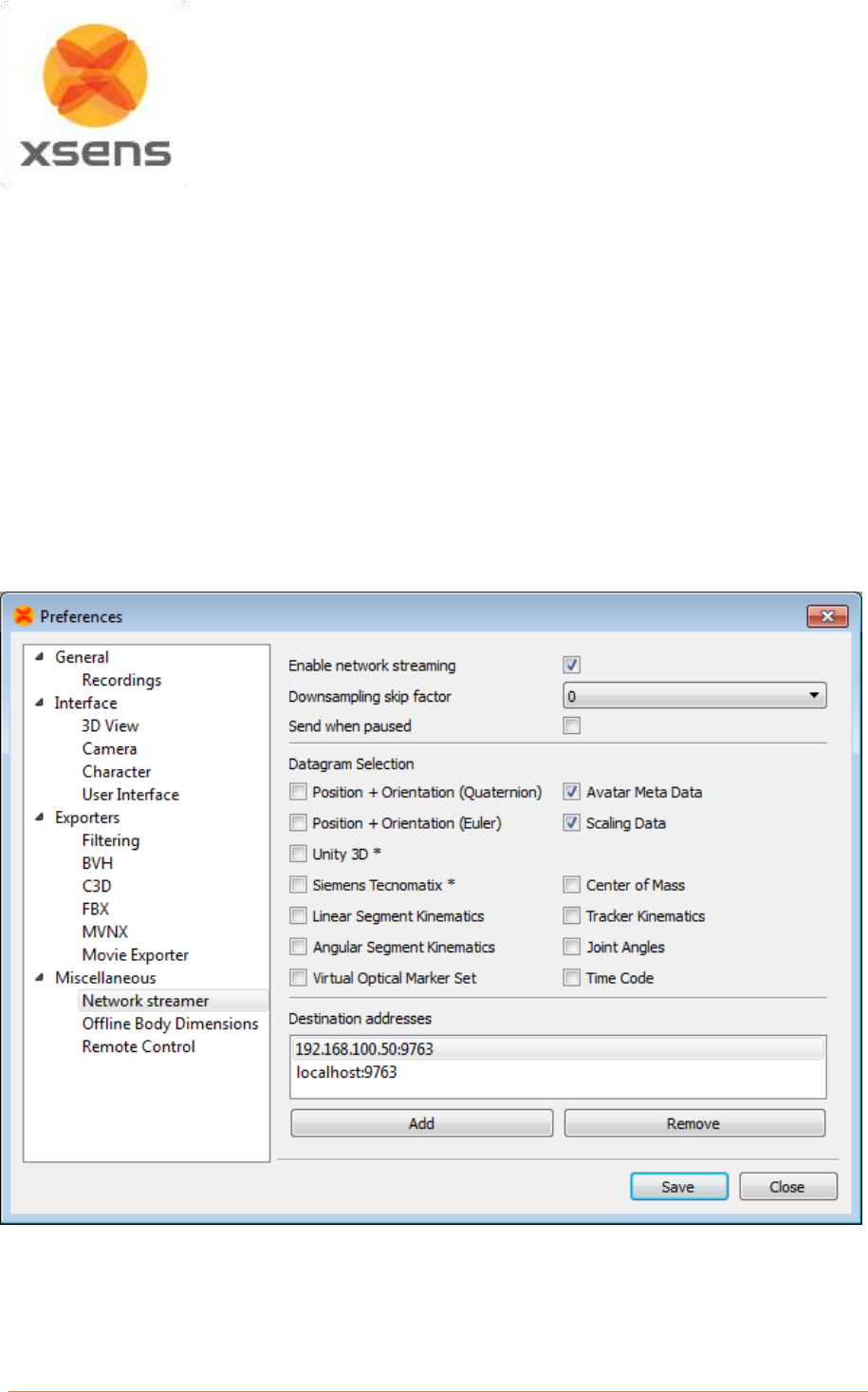
Document MV0319P.N
© Xsens Technologies B.V.
MVN User Manual
57
9.6 Network Streamer
The network streamer sends the poses of the active window (playback or real-time), both UDP and TCP
are supported by the network streamer. The UDP Protocol is unidirectional, and contrary to TCP
(Transmission Control Protocol, RFC 793) it is stateless and does not require the receiver to answer
incoming packets. This allows greater speed.
You can use a network monitor on another or same PC to receive this stream, or write your own receiver
in another application.
Change network streaming settings in Options >Preferences >Miscellaneous >Network Streamer.
To enable streaming, activate the ‘Enable network streaming’ checkbox. The receiving network address
can be entered in ‘Destination addresses’. Use ‘localhost’ to send/receive on the same computer. UDP
is the default protocol. To stream using TCP, it is important to specify this in the destination address, for
example: tcp://127.0.0.1:9763 or tcp://localhost:9763.
It is possible to stream to multiple destination addresses.
Figure 42: Network streaming preferences
Document MV0319P.N
© Xsens Technologies B.V.
MVN User Manual
58
Figure 42 above shows the Network Streaming preferences. The table below summarizes the
functionality of each selection. Please refer to the Real-Time Network Streaming Protocol Specification
for further details.
Datagram
Description
Position + Orientation
(Quaternion)
Positions and orientation of each body segment, orientations in
quaternion format, position units are in meters. This is the most accurate
and preferred format for new application development. Use this to stream
from one MVN Studio to another. Select the ‘Scaling Data’ for proper
visualization of the character mesh.
Position + Orientation
(Euler)
Position and orientation of each body segment. Orientations are Euler
and position data is in meters. This is the format needed to send data to
the MVN MotionBuilder Live plug-in. See the MVN MotionBuilder plug-in
user manual for further details.
Avatar Meta Data
Particularly useful when streaming data during multi-person capture,
when selected, this protocol streams information inserted about the
character including the character as inserted in the Navigator as well as
the ID of the Body Pack or Awinda Station.
This feature is supported by MVN Studio as a network monitor.
Avatar Scaling data
This packet contains scaling information about the character, including
the null pose definition and point definitions to scale a mesh.
Unity 3D
This setting should be selected in the network streamer for users of the
Unity plugin. See the Unity plugin user manual for more details.
Siemens Tecnomatix
For MVN BIOMECH customers, it is possible to stream data in real-time
to Siemens PLM software using this selection. See separate user manual
for set up.
Linear Segment
Kinematics
Absolute segment position, linear velocity and linear acceleration.
Angular Segment
Kinematics
Absolute segment orientation, angular velocity and angular acceleration.
Virtual Optical Marker Set
This protocol streams a set of virtual optical markers. This is the virtual
marker set for the 1.0 Motion Builder plug-in. This data is not supported
for playback in MVN Studio.
Center of Mass
Absolute 3D position of the center of mass.
Tracker Kinematics
Absolute 3D tracker orientation (quaternions) and free acceleration. Local
acceleration, angular velocity and magnetic field of the sensor
components.
This feature is not supported by MVN Studio as a network monitor.
Joint Angles
Data is contains point ID of the parent and child segment orientation and
the joint angle in X,Y,Z.
Time Code
MVN Studio contains a clock which starts running at the start of a
recording. The clock measures the elapsed time in milliseconds. When
data is sampled, the current value of the clock is also sampled and stored
in the datagram(s) as a 32-bit unsigned integer value representing a time
code. When this option is selected a string of this Time Code is streamed
(HH:MM:SS.mmm).
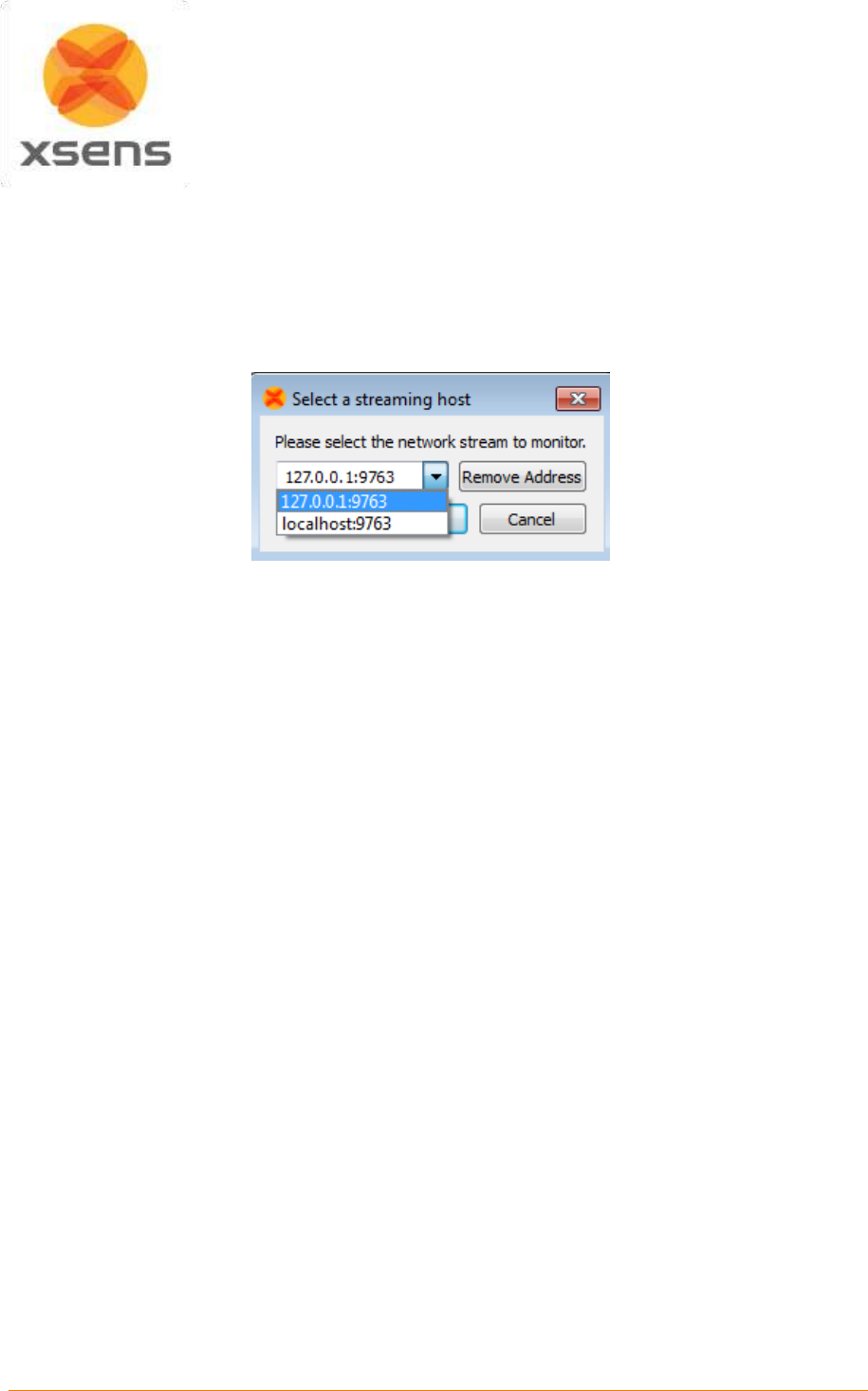
Document MV0319P.N
© Xsens Technologies B.V.
MVN User Manual
59
9.7 Network Monitor
MVN Studio also implements a Network Monitor that can receive the MVN network stream of motion
data. Note that this is mean only to monitor a network stream and no further functionality is provided
than viewing (i.e. no saving, recording, editing etc).
To open a network monitor in MVN Studio, go to File >Open Network Monitor or press “Ctrl+M”, to obtain
the menu shown in Figure 43.
Figure 43: Select streaming host
Here, enter the IP address of the sending computer or use ‘localhost’ if sending and receiving on the
same PC.
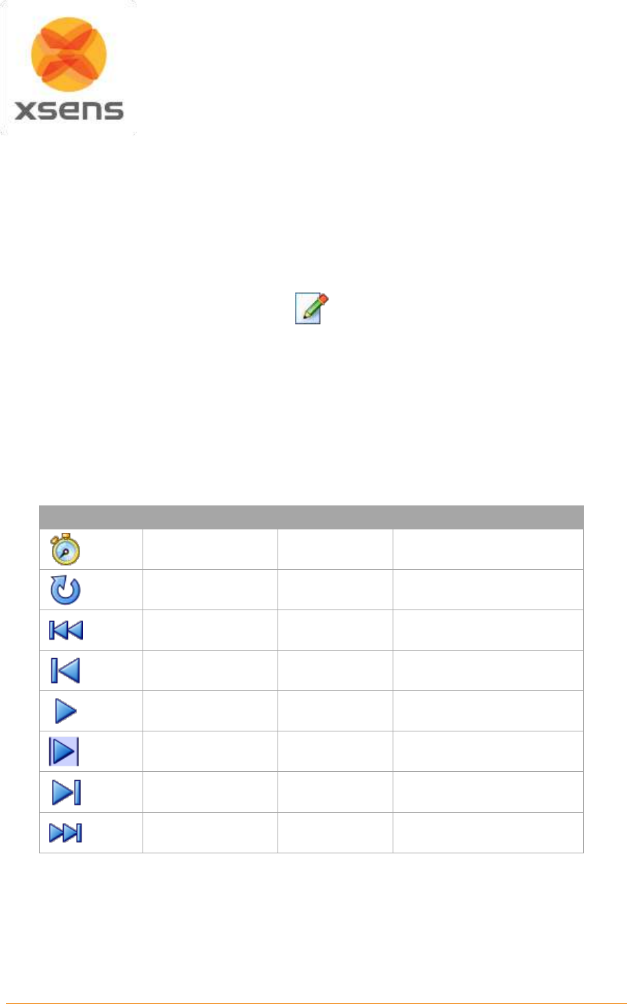
Document MV0319P.N
© Xsens Technologies B.V.
MVN User Manual
60
10 Playback and editing
When a file has been recorded, various new elements become possible, including playback of the
recorded file; depending on whether or not the video was used, this will also involve synchronized video
data. Furthermore, although intended for the analysis workflow stage only, graphs are available during
the Playback and Editing workflow stage to help in some post-processing tasks. Graphs are described
in detail in Section 11.1.
MVN files created with previous versions of MVN Studio can be played back in MVN Studio 3.0,
reprocessing may be necessary to get a good performance.
Playback and editing
10.1 Playback
Playback becomes possible with a recorded trial. To play and edit recorded files, open an MVN, MVNS
or MVNX file. The Playback Toolbar contains familiar playback options.
If multiple MVN, MVNS, or MVNX files are open, all files can be controlled at the same time using Global
Playback options. When analyzing similar recordings, to make all files jump to the same frame, simply
use the quick key ‘Shift + Down’.
Icon
Task
Short Key
Global Playback Short Key
Playback speed
Loop recorded data
R (toggle)
Shift + R
Go to start
Home
Shift + Home
Previous frame
Cursor left
Shift + Cursor left
Play / Pause
Space bar
Shift + Space bar
Play selection
Ctrl + Space bar
Next frame
Cursor right
Shift + Cursor right
Go to end
End
Shift + End
10.2 Synchronization with video
In MVN Studio Pro, MVN data with synchronized video is available. The accuracy of the software
synchronization depends heavily on the LAN connection to the camera and the wireless link quality to
the MVN system. In general, the time offset between the MVN frame and the video frame is negligible,
or less than 1-2 video frames.
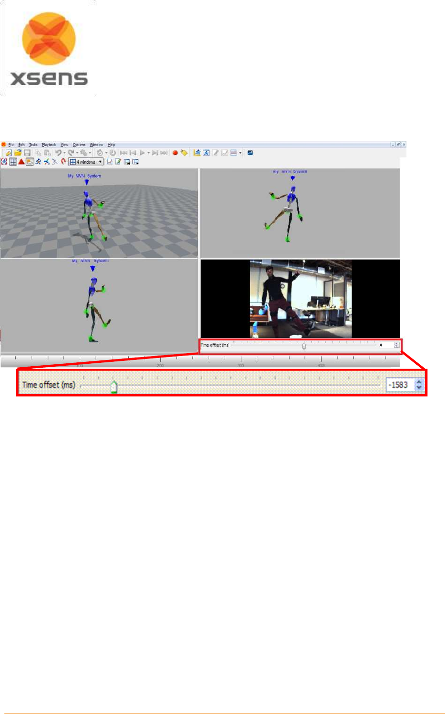
Document MV0319P.N
© Xsens Technologies B.V.
MVN User Manual
61
However, if there is a larger offset between the MVN and video data, time-synchronization can be
manually corrected using the sliding bar under the video. Drag the bar or use the numbers or the arrows
to change the offset [ms]. The offset is applied to the whole file. Any clock skew between the camera
and the MVN system is automatically estimated and corrected.
Figure 44: Video synchronization sliding bar
10.3 Contact point editing
The MVN Fusion Engine uses external contacts of the body with its surroundings to minimize position
drift of the computed body model with respect to the Origin (defined by starting point). A number of
points on the anatomical model have been defined that are likely to make contact with the external world.
An overview of these potential contact points is given in Table 5. The detection of external contacts is
based on measured kinematics of relevant body parts. In some cases, e.g., when a recording is made
on different floor levels (e.g. stair climbing), it can be desirable to overrule the automatically detected
contact points. Note that with MVN files recorded with earlier versions of MVN Studio, it is possible that
not all points will be available. Examples of contact point editing steps are given in Section 20.
During Playback and Editing, four default bars appear above the timeline, indicating presence of contact
points, advanced (floor level), position, and clipping edits (Figure 45). If there is a contact, the contact
will be shown in the viewport with a large blue sphere. When hovering above the ‘other contacts’ bar a
tool tip pops up indicating which contact point is active.
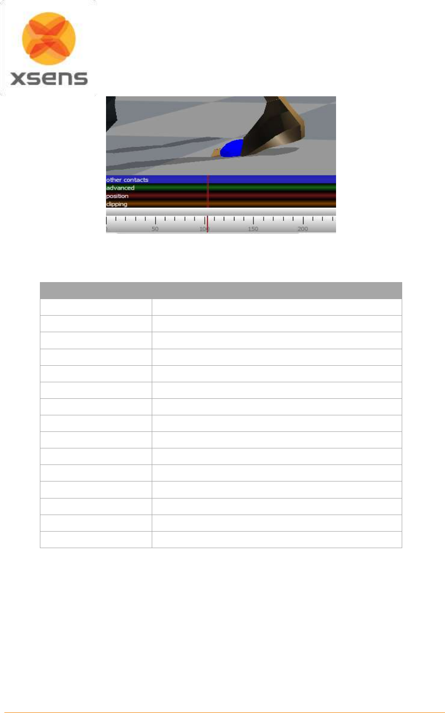
Document MV0319P.N
© Xsens Technologies B.V.
MVN User Manual
62
Figure 45: Contact point
Table 5: Potential contact points in MVN Studio
Contact point
Description
HeelFoot
Heel of the foot
FirstMetatarsal
Inside ball of foot
FifthMetatarsal
Outside ball of foot
PivotFoot
Center ball of foot
TibialTub
Bony elevation on upper part of the shinbone (tibia)
GreaterTrochanter
Eminence on the upper part of the femur
IschialTub
Buttock (left and right)
Sacrum
Base of the Spinal Column
Central Buttock
Buttock
PX
Bottom of sternum
T4SpinalProcess
Vertebra between shoulders
Acromion
Shoulder
Olecranon
Elbow
BallOfHand
Ball of hand
TopOfHead
Top of head
When clicking on a body segment with the left mouse button, the selected mesh will light up in red. The
selected body segment shows spheres with external points of that segment. The time bar will zoom in
and expand to show the detected contact points of the selected segment per frame. The colors of the
spheres correspond with the coloring and labeling in the contact bar. For example, on the foot, there are
four possible contact points: the heel (blue), first metatarsal (green), fifth metatarsal (red) and the pivot
point on the ball of the foot (pink).
When an external point is defined as a contact, the related sphere will enlarge for the currently displayed
frame. Clicking on a second segment will show the contacts of both selected segments.
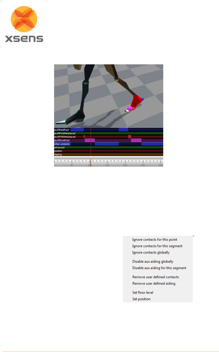
Document MV0319P.N
© Xsens Technologies B.V.
MVN User Manual
63
To scrub, drag the time line scroll bar ( ) to the left or right. Step through the time frames using the left
and right cursor or keep it pressed to move very slowly though the file, frame by frame.
Figure 46: Contact points on the 3D viewport and the contact editing menu
10.3.1 Selection of samples
The left mouse button (and drag) will set a contact for the selected contact point. The color of the user-
defined contact point will be slightly darker than the color of the original detected contact point. Only one
contact point can be selected per segment. To select contact points for multiple segments, hold the shift
key during selection with the left mouse button.
Note: The first contact editing action will take more time than the succeeding actions due to the caching
mechanism.
The right mouse button (and drag) will show
the contact point editing options for the
selected frames. In the next section, these
options will be explained.
To ensure that the changes are applied, click
reprocess – see Section 10.3.2.7.
Undo (‘Ctrl + Z’) and redo (‘Ctrl + Y’) the
performed contact point editing actions. Saving
the file commits the changes and they can no
longer be undone.
Figure 47: Right click menu in contact editing
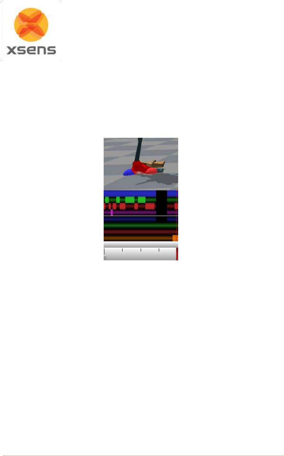
Document MV0319P.N
© Xsens Technologies B.V.
MVN User Manual
64
10.3.2 Contact point editing options
10.3.2.1 Remove user-defined
Revert to the original recording for the selected samples. Remove user-defined aiding refers to the
positions and floor levels set, as remove user-defined contacts refers to the contact points of the
segments. Reprocess to apply changes (see Section 10.3.2.7).
10.3.2.2 Ignore contacts globally
Removes all detected contacts for all segments.
Figure 48: Example of ignore contact globally
10.3.2.3 Ignore contacts for this segment
The selected segment will not make contact for the selected samples. The MVN Fusion Engine will mark
the most likely point of another segment as a contact.
10.3.2.4 Disable aux aiding
10.3.2.5 Set position
Sets the position and its uncertainty for the selected contact point. Optionally, only the height of a point
can be set. Set positions can be found in the set position bar.
With the position aiding interface, it is possible to set a contact point at a desired coordinate (X, Y and
Z). This can be useful in situations which are not supported by one of the user scenarios (e.g. walking
stairs). Examples: (1) the starting position of a recording can be set to zero, (2) when the subject is
hanging on a bar, the position of the hands can be fixed at a given height, (3) when a subject steps onto
an object, the height of the contact can be ‘frozen’ to the height of the object, (4) when a subject jumps
down from an object, the position of the foot can be set to the height of the object before jumping. Note
that some situations, such as walking on an elevated surface can also be accomplished by setting the
floor height.
In the contact bar, right-click the desired time frame(s) and select the option ‘set position’. In the dialog,
the X, Y and Z positions of the selected segment point of the current time frame are given.
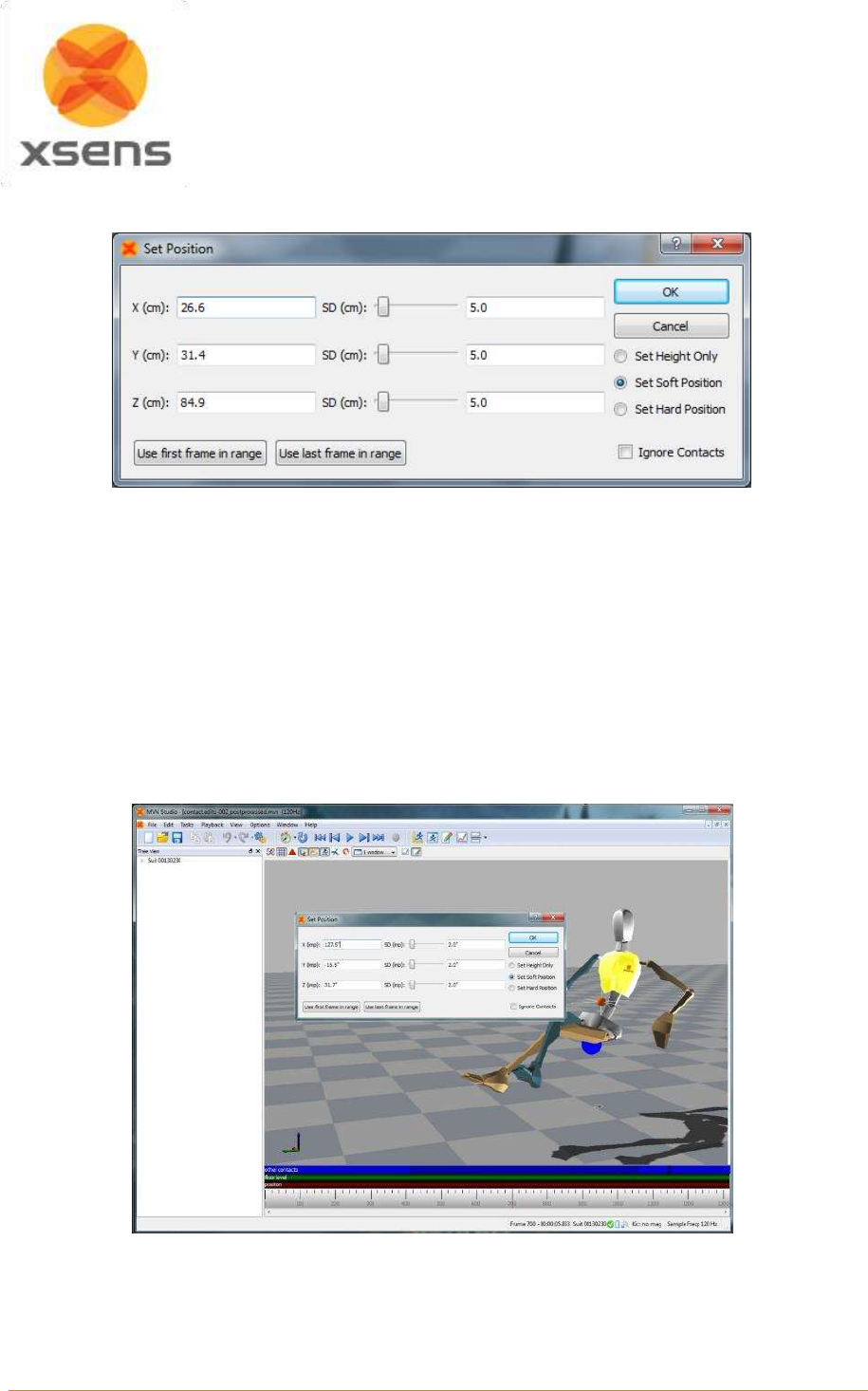
Document MV0319P.N
© Xsens Technologies B.V.
MVN User Manual
65
Note: in MVN Studio, height is indicated by ‘Z’.
Figure 49: Set position menu during contact point editing
The SD slider sets the standard deviation, which is an indication of how much the aiding point can be
trusted in combination with the computed position of the MVN Fusion Engine. This option can also be
used creatively for example to create a “soft” landing on a mattress. With the ‘Force no contacts’ options,
no other contacts will be detected during the selected frames. The contact bar will show a dot in the
center of the edited frame and mark all other contact points dark. The ‘Absolute’ option completely
overrules the computed position of the MVN Fusion Engine. The contact bar will show a ‘P’ at the
selected frame. After editing the co-ordinates, click the reprocess button.
Always work chronologically when setting positions of contact points, since an edited position at frame
k will influence the position at frame k+1 and further.
Figure 50: Example of using contact point aiding for seated position
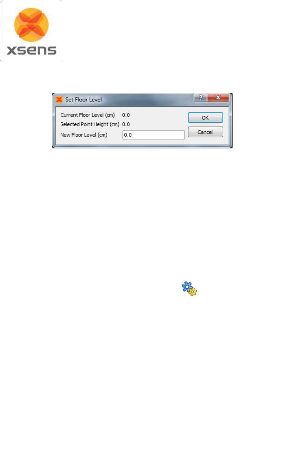
Document MV0319P.N
© Xsens Technologies B.V.
MVN User Manual
66
10.3.2.6 Floor level
Sets the height of the floor. Multiple floor levels can be set in one file. The current floor level is presented
in the dialog; see Figure 51 for an example.
Figure 51: Set floor level menu
Right mouse click on a contact bar to set the floor height to the height of that contact. The contact
detection will now be applied on the new floor height for all following samples.
Left mouse click and drag on the advanced bar allows you to set a floor height for a range of frames
10.3.2.7 Clipping
The clipping bar indicates when clipping has occurred in the data. This gives users an indication of when
movement has caused sensor data to be exceeded. Data should not be trusted at these times.
10.4 Reprocessing
MVN files contain all original data and can be used to re-process the file using other settings and
assumptions or with overruled external contacts, if needed. Anytime a change has been made to a file,
e.g. contact points, change of fusion engine, subject dimensions or use of MVN Awinda to contain
retransmitted data etc., the file must be reprocessed to ensure that the changes are implemented. It is
advisable to save the reprocessed file with a new filename, to be able to return to the original values.
To enable reprocessing press ‘Ctrl+Shift+P’ or click the icon:
The result of clicking the above icon can be changed from ‘Reprocess’ to ‘Auto-reprocess’ by clicking
on the dropdown arrow to right of the icon.
The upper bar will show the progress of the currently displayed frames when zoomed in. The lower bar
will show the progress of the total file. Once the upper bar has been completed, you can continue editing
frames in the current window. After the first pass, the progress bar will be green and the MVN Fusion
engine will apply the edited contact points.
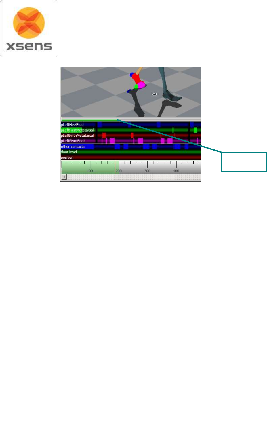
Document MV0319P.N
© Xsens Technologies B.V.
MVN User Manual
67
Figure 52: Contact editing reprocess bar
If many contacts have been inaccurately detected specifically on one side of the body, it is likely to be
caused by inaccurate calibration. Check that the MT’s of the legs and pelvis have not moved. Also check
that the body dimensions are correct. If necessary, repeat a basic calibration (N or T pose).
If the lower leg protrudes through the foot during landing following a jump, the foot that pushed-off was
probably detected as a contact for too long. This is remedied by removing the contacts of last few frames
before the push-off.
The orthogonal view in the sagittal plane (Y) is a helpful way of determining exactly when the foot strikes
the ground. It may help to remove all contacts for an interval around the expected contact frame to
determine the time frame of contact.
To remove all edited contact points and let the MVN Fusion Engine detect contact points automatically,
select ‘Edit >Remove all user defined’. Reprocess to apply changes.
10.5 Multi-person editing
In the MVNS file, the contact and aiding points for each character can be edited separately. Click on
one of the segments of the character you want to edit and follow the workflow as described in Section
10.3.
The body dimensions and scenario can also be changed in the calibration for the selected character.
For each suit, a separate export file will be generated when exporting to MVNX, BVH or FBX, C3D see
Section 12.
Reprocess
progress bar
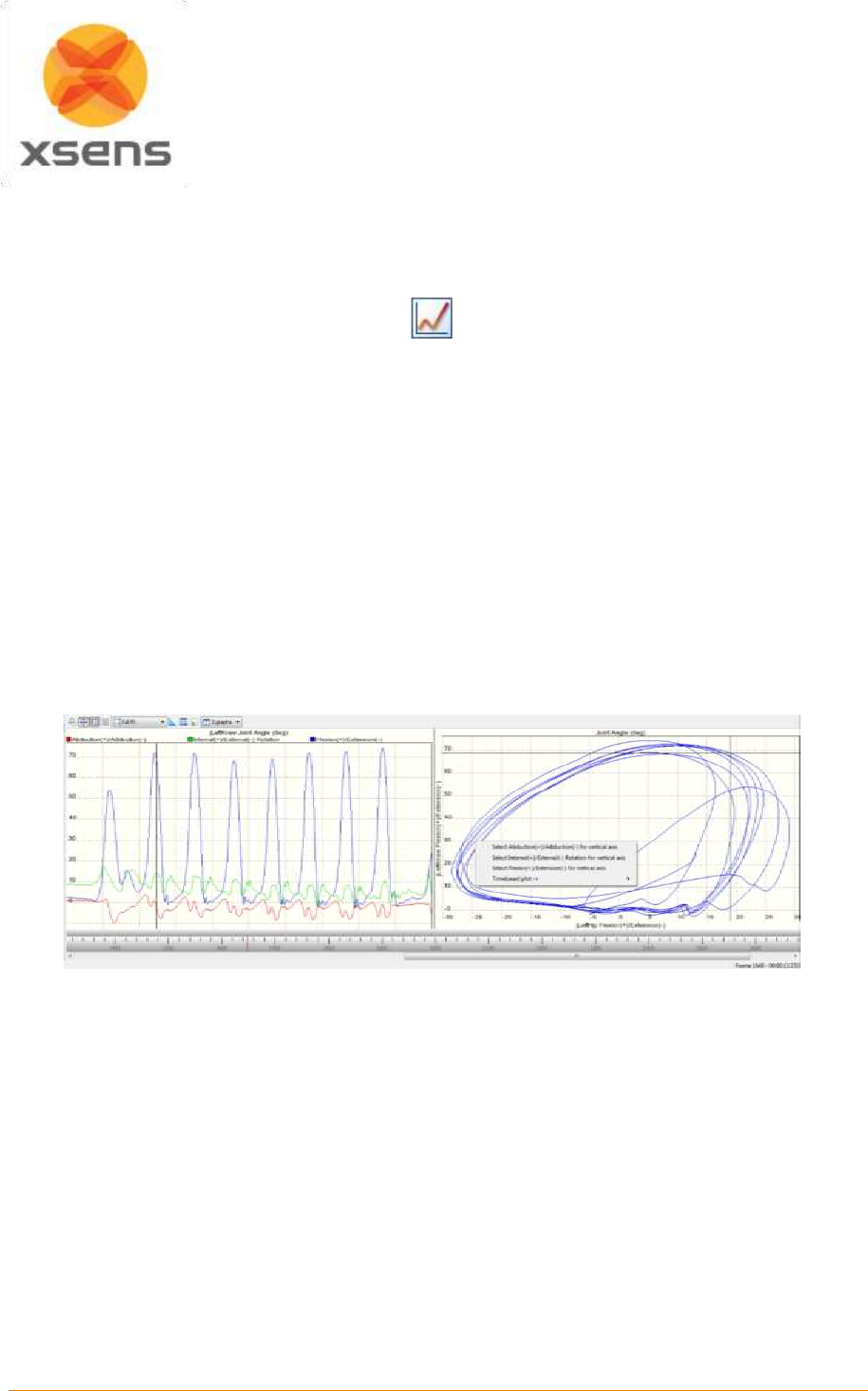
Document MV0319P.N
© Xsens Technologies B.V.
MVN User Manual
68
11 Data Analysis
The final stage of the work flow is ‘Data Analysis’. The major feature of the analysis stage is kinematic
graphs.
11.1 Graphs
In the analysis workflow stage, a graph appears in the interface. To view a graph of a given parameter,
click and drag the parameter from tree view to the graph. Two types of graphs are possible: time vs.
parameter and parameter vs. parameter (Coordination [or phase] Plots).
11.1.1 Parameter vs. Time
Drag and drop a parameter with the left mouse button to create a parameter vs. time graph. Click on the
colored boxes in the legend to disable/enable data in a given plane.
11.1.2 Coordination / Phase Plots (Parameter vs. Parameter)
Drag and drop a parameter with the right mouse button to the horizontal or vertical of the graph to create
a parameter vs. parameter graph. Select the variable to plot from the menu. On the remaining axis,
another axis of the parameter will be displayed as default. Repeat the process to plot the desired
parameter on the remaining axis. See Figure 53 for an example of graph types.
Figure 53: 2D graphs: Time vs. Parameter on the left hand side and parameter vs. parameter on the right
hand side
Note that graphs show the angular velocity in degrees per second. In MVNX files, the angular velocity
is exported in radians per second.
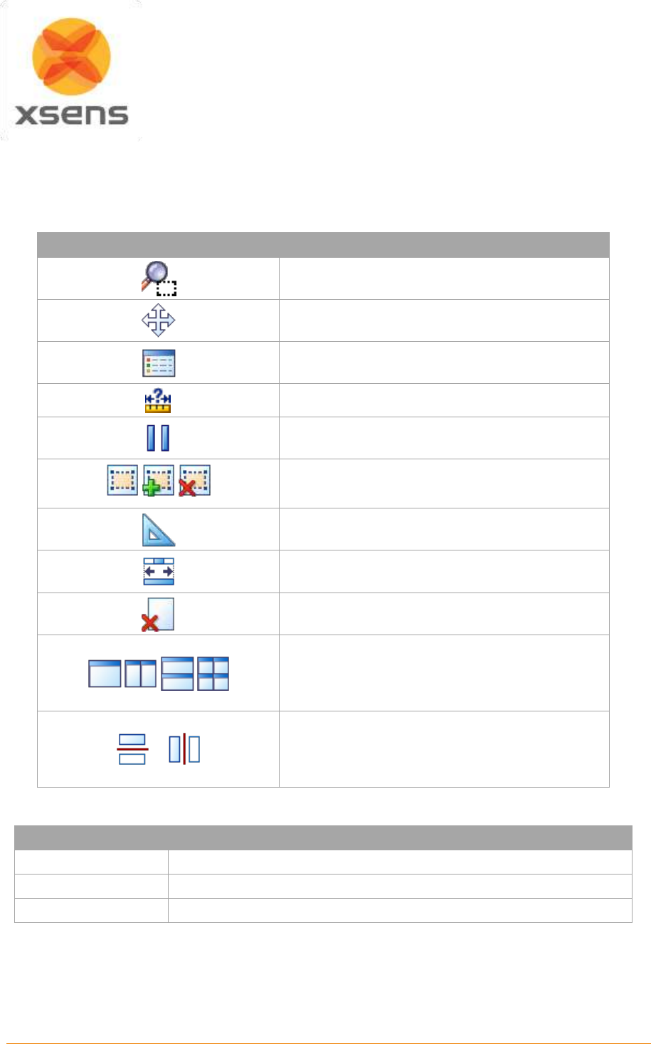
Document MV0319P.N
© Xsens Technologies B.V.
MVN User Manual
69
11.1.3 Graph handling
Zoom and pan in the graph using the icons in the toolbar. The time on the time vs. parameter graphs
conforms to that shown in the time bar.
11.1.4 Graph toolbar
Icon
Task
Zoom
Pan
Show/hide legend
Show numerical value on graph
Freeze graph (not yet available)
Scaling options: Full fit, Expand to fit, No auto
scaling
Equal axes
Show all samples (always on)
Clear graphs (not yet available)
Amount and layout of graphs
Horizontal / Vertical graph view (on main tool bar
but used only in combination with graphs)
11.1.5 Scaling Options
Scaling option
Functionality
No auto scaling
Y-scale will no longer be scaled
Expand to fit
Y-scale will be stretched to show all data in plot
Full fit
Y-scale will be stretched to show all data in plot
11.1.6 Zoom
To zoom, select the “No auto scaling” option. Zoom only takes place on the vertical axis. To zoom in
time use the mouse wheel in the time line to zoom horizontally to a point in time.
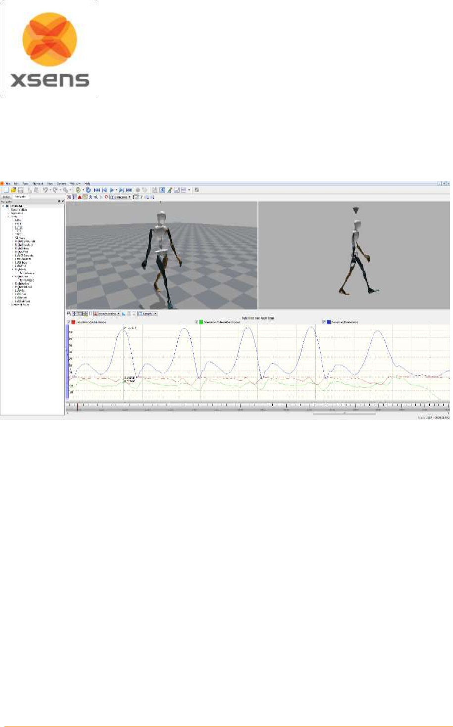
Document MV0319P.N
© Xsens Technologies B.V.
MVN User Manual
70
11.1.7 Pan
To use the pan function, enable “no auto scaling”, click in the graph area with the left mouse button and
drag up or down, to pan. Note that it is not possible to pan to an area with no data. When data is available
beyond the limits of the vertical axis it is possible, using the cross bar to pan, and also using a purple
scroll bar, which appears on the side of the graph when there is a large difference between vertical
values, as Figure 54 shows.
Figure 54: Pan and Numerical Values on Graphs
11.1.8 Show/ Hide Legends
Often it is already understood what the colors of the graphs represent. To save room, the legends can
be hidden by toggling the Show / hide legend icon.
11.1.9 Show Numerical Values on Graphs
Using this icon, the numerical value on the graph is visible. It is possible that at times the lines intersect
and the values are not clearly visible, when this happens; remove one line from view by disabling this in
the tick box in the legend. In this way the value of one line at a time is made visible. See Figure 54 for
an impression of how the numerical values appear in the graph.
11.1.10 Equal axes
This tool is used with the phase / coordination plots. Toggle between Equal Axes and “Full Fit” depending
on the detail required.
11.1.11 Amount and layout of graphs
There are a number of pre-defined layouts available, which can be selected from the drop down menu.
Additionally, there is a possibility for the user to define a custom amount and layout of the graphical
representation. When “Custom” is selected, a new area appears where the user can insert the number
of rows by columns to view.

Document MV0319P.N
© Xsens Technologies B.V.
MVN User Manual
71
11.2 Cascade / Tile windows
Multiple trials can be opened simultaneously and played and edited. Viewing a live performance is also
possible in playback. Use the ‘Window >Cascade / Tile’ menu to select the window layout.
11.3 Linked views
When multiple windows are active, their views can be linked. Upon enabling Linked Views, the scene of
all windows will be reset such that the origin faces the same direction. When the view in one window is
changed, the view in the other window will change accordingly. Use ‘Options >Linked Views’ to toggle
the linked views option.

Document MV0319P.N
© Xsens Technologies B.V.
MVN User Manual
72
12 Saving and Exporting
When a recording has been made, two files are created and saved automatically, one with the file
extension “.mvn” and the other with the file extension “.mvns”. If synchronized video data is recorded, a
movie file “.mpg” is also saved automatically.
MVN (MVN native file) is the most comprehensive format and contains all measured inertial sensor data,
and all kinematic data of each segment. It is a binary proprietary format and can only be used by MVN
Studio or by using the SDK. The MVN files contain all original data and can be used to re-process a
recording using other settings and assumptions or with overruled external contacts. To copy a part of
an MVN file to a new MVN file, select the frames and go to >Edit >Copy to MVN, press ‘Ctrl+B’ or right
click the Timeline.
MVNS is the MVN session file. It contains information about the recorded trials, it is necessary to open
an MVNS file if video data was recorded, or to playback and edit time-synchronized multi-person
recordings.
If video data was recorded, opening the file with extension .mvn will open only the MVN data – the 3D
character in the viewports. Therefore to watch synchronized video data with the MVN data, open the file
with the “.mvns” extension, which will call both the .mpg and the related .mvn files.
If MVN Studio was used for multi-person capture, data of each character is saved in a separate MVN
file, which is synchronized based on the internal clock of the XMs for each suit. This means that for long
files, the number of frames between simultaneously recorded MVN files can differ. However, these MVN
files are grouped in the MVNS file. All recordings in an MVNS file are opened in the same 3D viewport
and will be played back simultaneously. In the MVNS file, all tracks have the same number of frames.
The MVN files will all have the same session name with the suit number as a suffix. For example, the
MVNS file ‘Skating-002.mvns’ consists of two MVN files: ‘Skating-002-suit00.mvn’ and ‘Skating-002-
suit01.mvn’.
MVN (MVN and MVNX) files can be exported to C3D, FBX, BVH or MVNX format. Before exporting a
file to a given format, ensure that the settings are correct. To do this, go to >Options >Preferences
>Exporters. Then go to >File >Export >Export File and select the desired export format. For batch
processing of all active captures, go to >File >Export >Export All Open Files. For batch processing of a
complete folder, go to >File >Export >Batch export. To export only a selected portion of an MVN or
MVNX file go to >File >Export >Export Selection.
There are five main exporters, BVH, C3D, FBX, MVNX, and a Movie Exporter. Each exporter has its
own menu in the preferences section.
12.1 Applying (Smoothing) Filters to Exported Data
The first option to set in the exporters preferences is the filtering. This setting is used only for BVH and
FBX.
12.1.1 Exporter smoothing
The highly sensitive sensor modules capture every twitch and deliver very crisp data. For some
applications, more smoothed motion data is desired. Three options are available:
No smoothing
Light smoothing
Heavy smoothing
The Export Smoothing Filter does not introduce a phase lag. Light smoothing is generally the
recommended option.
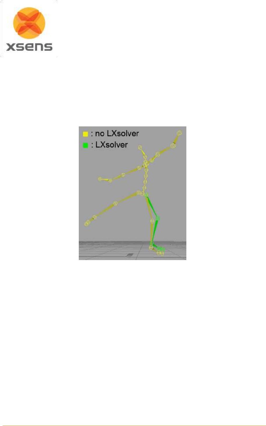
Document MV0319P.N
© Xsens Technologies B.V.
MVN User Manual
73
12.1.2 Output filtering: LXsolver
The MVN fusion engine allows some laxity between joints to allow for small errors due to for example
soft tissue movement. In the FBX export file, the positions and orientations of all segments as captured
are exported. In BVH, only the position of the root (pelvis) is exported. The other segments are rigged,
based on Euler angles with respect to the previous segment. Since the captured position of the foot can
be different than the rigged position, it can result in foot slide.
The LXsolver exports the data to a form that minimizes soft tissue artefacts and joint laxity while keeping
the feet at place. By default it is active on FBX and BVH and performed after the smoother.
Figure 55: Comparison of MVN results with and without LXsolver
12.2 BVH
The name BVH stands for BioVision Hierarchical data, and embeds captured motion data in ASCII
format which can be imported in many animation applications.
A BVH file consists of two parts, a header section which describes the hierarchy and initial pose of the
skeleton; and a data section which contains the motion data. The start of the header section begins with
the keyword ‘HIERARCHY’. The following line starts with the keyword ‘ROOT’ followed by the name of
the root segment of the hierarchy to be defined, usually the hips. Each segment contains a vector
indicating the length and direction from the parent segment. The vector is specified by the keyword
‘OFFSET’ followed by the X, Y and Z values. The ‘CHANNELS’ keyword indicates the number of
channels for this segment (usually 3 Euler angles) together with the order of rotation. On the next line,
either you will find the ‘JOINT’ keyword or the ‘End Site’ keyword. The end site information ends the
recursion and indicates that the current segment is an end effector (has no children). The end site
definition gives the length of the preceding segment just like the offset of a child defines the length and
direction of its parents segment. The world space is defined as a right handed coordinate system with
the Y axis as the world up vector.
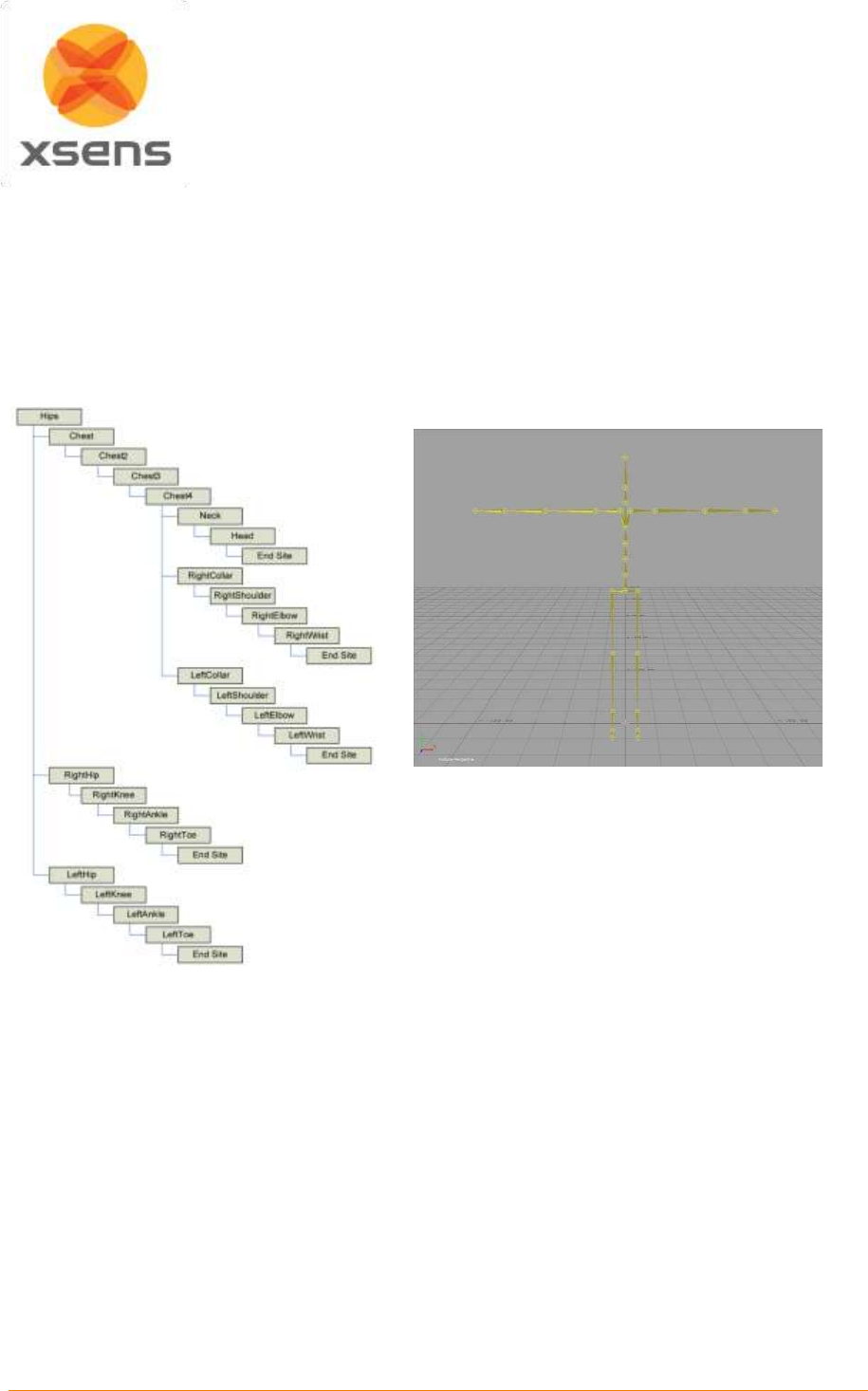
Document MV0319P.N
© Xsens Technologies B.V.
MVN User Manual
74
In the default BVH hierarchy, the character is in a T-pose. Use the 3ds Max exporter to write a neutral
pose (arms parallel to body). Use the Poser exporter to reduce the number of chest segments from 4 to
2.
The motion section begins with the keyword ‘MOTION’. This line is followed by the number of motion
frames by the keyword ‘Frames’ and ‘Frame Time’, indicating the sampling rate of the data. The rest of
the file contains the actual motion data; the X, Y and Z position of the root segment and Euler angles of
each segment with respect to its parent segment. Each line is one sample of motion data. The numbers
appear in the order of the channel specifications as the skeleton hierarchy was parsed.
It should be noted that the BVH format is restrictive and it does not reflect the full information as captured
with MVN. The numerical resolution of BVH files is limited compared to the MVN and MVNX files. The
Euler angle conversion may cause round-off issues in certain poses (singularities). Since all segments
are rigidly connected (which is not the case in the MVN Fusion Engine) some foot slide may occur since
all errors such as mainly soft tissue artefacts are ‘projected’ on the feet. However, the LXsolver removes
this on export, see 12.1.2. Further optimization can be done by using inversed kinematics (IK) solvers
which are usually available in animation applications and which are also necessary for retargeting the
motion data to different characters.
The BVH format does not support multi-person recordings. For each person a separate BVH file will be
made.
Set the BVH preferences. An explanation of each option is provided below.
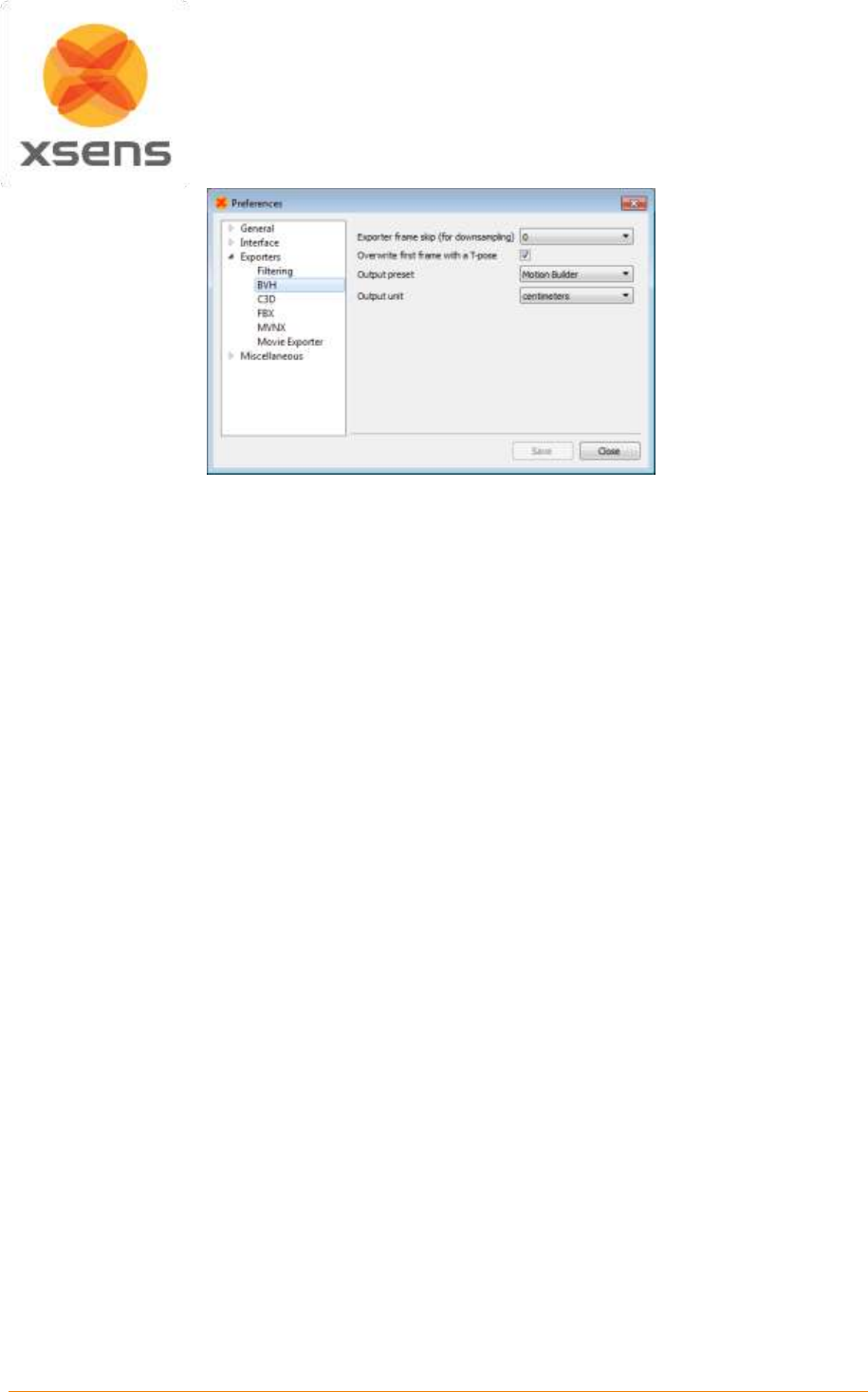
Document MV0319P.N
© Xsens Technologies B.V.
MVN User Manual
75
Figure 56: BVH Preferences Menu
12.2.1 Frame skip
The frame skip number (n) is used to reduce the frame rate of the output. The exporter will perform
down sampling by skipping every n frames (n = 0 to 10) of the original file (after smoothing) in the output.
Note that if no smoothing is specified, no smoothing will be applied when using frame skip.
The output rate is given by: original sample rate / (1 + skip factor).
For example, an MVN file recorded at 100 Hz:
frame skip = 1, output frame rate = 50 Hz
frame skip = 2, output frame rate = 33 Hz
frame skip = 3, output frame rate = 25 Hz
Or for example, an MVN file recorded at 240 Hz:
frame skip = 1, output frame rate = 120 Hz
frame skip = 2, output frame rate = 80 Hz
frame skip = 3, output frame rate = 60 Hz
So, take care when selecting your preferred motion capture update rate if you need a specific output
frame rate, it can make your life easier.
12.2.2 Overwrite first frame with T-pose
To align the captured motion data with an animation model, the T-pose will actually be inserted before
the first frame of the data. The position and orientation of all segments can be found in the MVNX file in
the <tpose>section.
12.2.3 Output Presets
Several Output Presets are available that fit specific applications:
Motion Builder
3D Studio Max
Poser 6
12.2.4 Output Unit
Select the desired output unit that is used in the animation program.
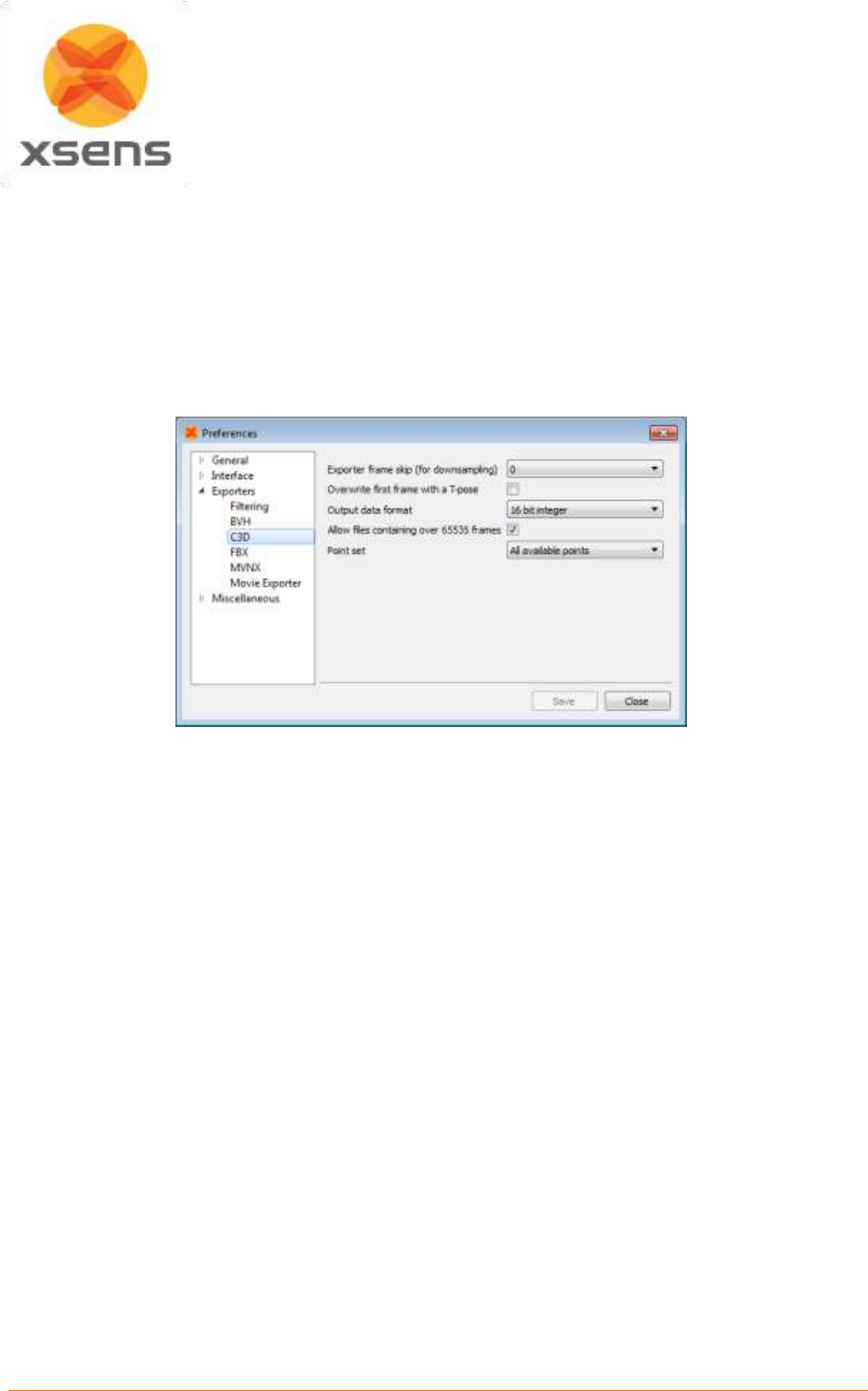
Document MV0319P.N
© Xsens Technologies B.V.
MVN User Manual
76
12.3 C3D
C3D means “Coordinate 3D”; as the name suggests it is a file format designed to contain 3D coordinate
data, usually in the form of bony landmarks. It has also been designed to contain analog data. The 3D
and analog samples are interleaved, frame-by-frame, throughout the data in a straightforward manner.
C3D data can contain 3D, 2D, analog data or a combination. In addition, it is possible (although not very
efficient) to store the results of kinematic calculations (angles, moments, accelerations etc.) within the
3D data record format. To facilitate biomechanics users, C3D is a new export format in MVN Studio 3.0
Pro. The menu in Figure 57 shows the possibilities allowed for C3D export.
Figure 57: C3D Exporter interface in Preferences menu
There are two lists of points that can be exported, “All available points” and “External Points”. External
Points are included in the “All available” selection. Section 12.3.1 is a list of the anatomical landmarks
exported by C3D. Just like BVH, C3D data can be downsampled prior to exporting.
Most systems accept the 16 bit integer output format. However, when this is not the case, the single
precision floating point (IEEE 754) can be chosen, which will enhance resolution (less output
quantization).
In the past C3D was designed to accept no more than 65535 frames. Tick the box to allow trials longer
than 65535.
A prop will be exported in C3D with tags: ‘origin’, ‘tip’ and ‘extra’.
Exported C3Ddata has been successfully tested in C-Motion’s Visual 3D.

Document MV0319P.N
© Xsens Technologies B.V.
MVN User Manual
77
12.3.1 Points exported in C3D Exporter
For an illustration of the location of the points, see Figure 68.
1
pHipOrigin
33
pRightTopOfHand
2
pRightASI
34
pRightPinky
3
pLeftASI
35
pRightBallHand
4
pRightCSI
36
pLeftTopOfHand
5
pLeftCSI
37
pLeftPinky
6
pRightIschialTub
38
pLeftBallHand
7
pLeftIschialTub
39
pRightGreaterTrochanter
8
pSacrum
40
pRightKneeLatEpicondyle
9
pL5SpinalProcess
41
pRightKneeMedEpicondyle
10
pL3SpinalProcess
42
pRightMiddleKneeCap (or pRightPatella)
11
pT12SpinalProcess
43
pLeftGreaterTrochanter
12
pPX
44
pLeftKneeLatEpicondyle
13
pIJ
45
pLeftKneeMedEpicondyle
14
pT4SpinalProcess
46
pLeftMiddleKneeCap (or pLeftPatella)
15
pT8SpinalProcess
47
pRightLatMalleolus
16
pC7SpinalProcess
48
pRightMedMalleolus
17
pTopOfHead
49
pRightTibialTub
18
pRightAuricularis
50
pLeftLatMalleolus
19
pLeftAuricularis
51
pLeftMedMalleolus
20
pBackOfHead
52
pLeftTibialTub
21
pRightAcromion
53
pRightHeelFoot
22
pLeftAcromion
54
pRightFirstMetatarsal
23
pRightArmLatEpicondyle
55
pRightFifthMetatarsal
24
pRightArmMedEpicondyle
56
pRightPivotFoot
25
pLeftArmLatEpicondyle
57
pRightHeelCenter
26
pLeftArmMedEpicondyle
58
pRightToe
27
pRightUlnarStyloid
59
pLeftHeelFoot
28
pRightRadialStyloid
60
pLeftFirstMetatarsal
29
pRightOlecranon
61
pLeftFifthMetatarsal
30
pLeftUlnarStyloid
62
pLeftPivotFoot
31
pLeftRadialStyloid
63
pLeftHeelCenter
32
pLeftOlecranon
64
pLeftToe
If props have been used in the measurement, these will also be exported in the C3D file. The parameters
of the props are Extra, Origin and Tip. If more than one prop has been used, the label will be appended
with “_” and the number of the prop (2 onwards). To use the point, as with the output points of the
biomechanical model, use the label “Origin”. Tip and Extra are needed to calculate the orientation of the
prop.
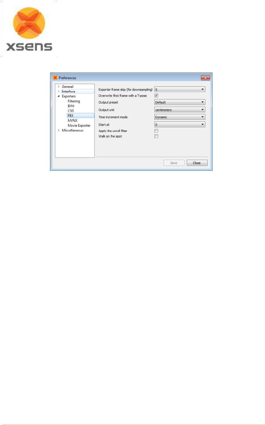
Document MV0319P.N
© Xsens Technologies B.V.
MVN User Manual
78
12.4 FBX
Figure 58: FBX Preferences Menu
FBX (Filmbox) is a platform-independent 3D file format which gives you access to content authored in
software packages such as MotionBuilder, Maya, Unity or Softimage. For some software packages, an
FBX plug-in should be installed.
FBX files contain both position and orientation information of all 23 segments. The FBX file will also
contain the frame time format. Go to >Options >Preferences >Exporters >FBX … and select the
timestamp output mode. To store the appropriate time code in an FBX file, the FBX exporter plug-in
must be set to “Dynamic time increments" and "Start at real start time” as seen in Figure 58. This figure
also shows that many of the options for FBX are also applicable to BVH. For details, see the above
descriptions for the items on the BVH menu.
Under Output preset you have the option to choose “Default” and “Skeleton”. “Default” export contains
position and orientation information of all 23 segments in global coordinates. “Skeleton” export contains
skeleton hierarchy information in a way that is used by many common 3D software packages like
MotionBuilder, Maya, Unity and Houdini.
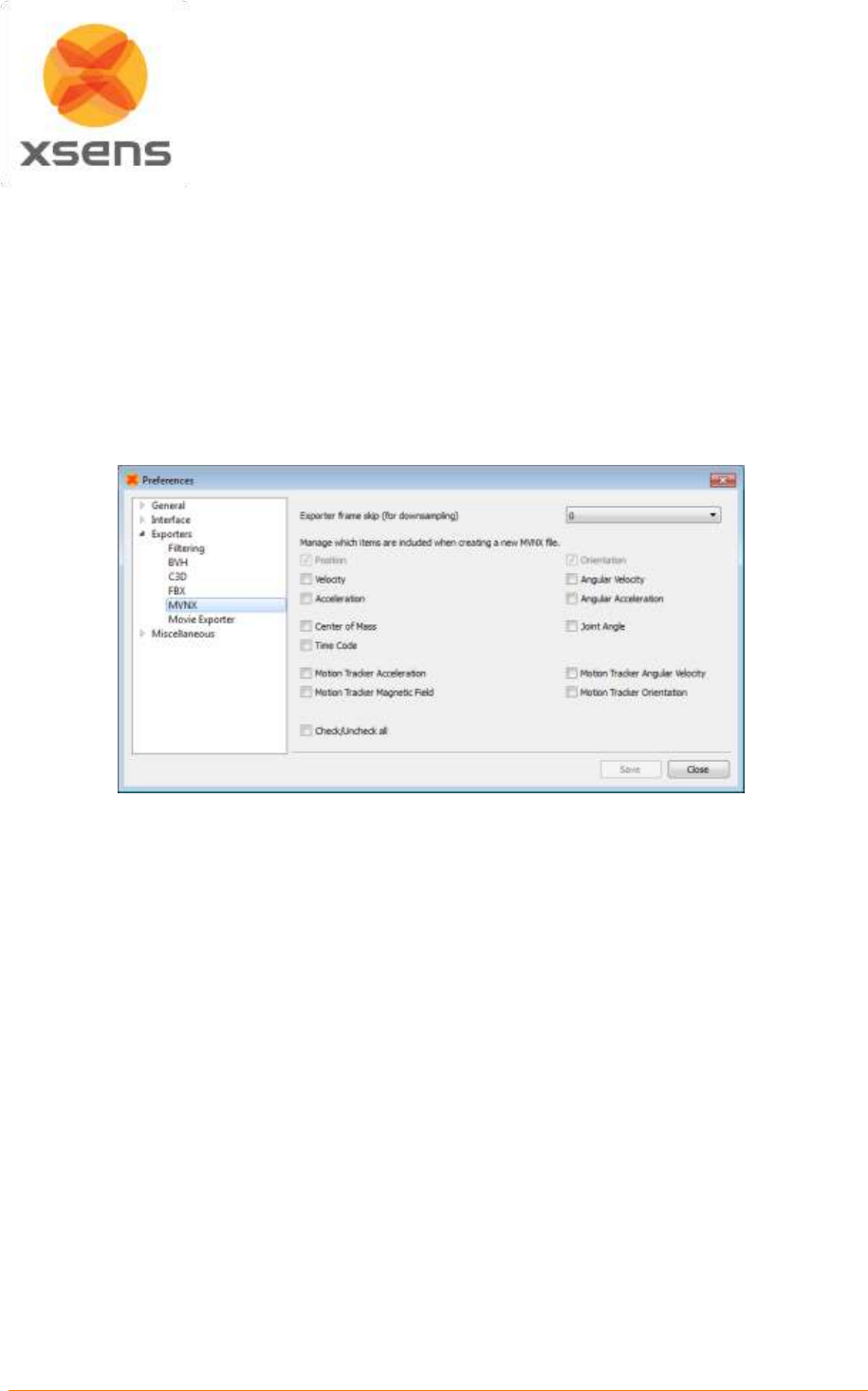
Document MV0319P.N
© Xsens Technologies B.V.
MVN User Manual
79
12.5 MVNX
MVNX (MVN Open XML format) files are provided. These are XML files that can be opened in programs
such as MICROSOFT EXCEL, ACCESS and MATLAB; see section 22 for help importing these files to
MATLAB and EXCEL. MVNX contains as default, 3D segment and position data.
Additional values can be exported as Figure 59 shows, including:
3D Position, linear and angular acceleration and velocity of all 23 segments.
3D Joint angles of 22 joints.
3D Orientation, acceleration, angular velocity and magnetic field data of all 17 MT’s.
Since MVN 4.0, a time code field is also available.
Figure 59: MVNX Preferences Menu

Document MV0319P.N
© Xsens Technologies B.V.
MVN User Manual
80
The entire MVNX structure is as follows:
<?xml version="1.0" encoding=" UTF-8"?>
<mvnx version=“3”>
<mvn version=“…” build=“…”/>
<comment></comment>
<subject label=“Suit…” frameRate=“…”segmentCount=“…”recDate=“…”originalFilename=“…”>
<comment></comment>
<segments>
<segment label=“…” id=“…”>
<segmentScale>
<offset>X Y Z </offset>
<rotation>=“r11 r12 r13 r21 r22 r23 r31 r32 r33”</rotation>
</segmentScale>
<points>
<point label=“…”>
<pos_s>X Y Z</pos_s/>
</point>
etc.
</points>
</segment>
etc.
</segments>
<sensors>
<sensor label =“…”/>
etc.
</sensors>
<joints>
<joint label=“…”>
<connector1>…</connector1>
<connector2>…</connector2>
</joint>
etc.
</joints>
<frames segmentCount= “…” sensorCount= “…” jointCount= “…”>
<frame time= “…” index= “…” type =“normal”>
<orientation>GBqseg1 GBqseg2 …etc… GBqseg23</orientation>
<position>Gposseg1 Gposseg1 …etc… Gposseg23</position>
<velocity>Gvseg1 Gvseg2 …etc… Gvseg23 </velocity>
<acceleration>Gaseg1 Gaseg2 …etc… Gaseg23 </acceleration>
<angularVelocity>Gwseg1 Gwseg2 …etc… Gwseg23</ angularVelocity >
<angularAcceleration>Gawseg1 Gawseg2 …etc… Gawseg23</angularAcceleration>
<sensorAcceleration>Sasen1 Sasen2 …etc… Sasen17 </sensorAcceleration>
<sensorAngularVelocity>Swsen1 Swsen2 …etc… Swsen17</sensorAngularVelocity>
<sensorMagneticField>Smsen1 Smsen2 …etc… Smsen17</sensorMagneticField>
<sensorOrientation>GSqsen1 GSqsen2 …etc… GSqsen17</sensorOrientation>
<jointAngle>jjnt1 jjnt2 …etc… jjnt22</jointAngle>
<jointAngleXZY>Jjnt1 Jjnt2 …etc… Jjnt22</jointAngleXZY>
<centerOfMass>GCseg1 GCseg2 …etc… GCseg23 </centerOfMass>
<marker>“name” </ marker >
Document MV0319P.N
© Xsens Technologies B.V.
MVN User Manual
81
</frame>
etc.
</frames>
</subject>
<securityCode code= “…” />
</mvnx>
The MVNX file starts with the XML version number and a reference to the DTD (Document Type
Definition). Then the root element “mvnx” with a reference to the XSD (XML Schema Definition) and the
MVNX version This is followed by a field “mvn”, containing the MVN Studio version and build details with
which this MVNX file was produced, followed by the comments that were added to the original recording:
<?xml version="1.0" encoding=" UTF-8"?>
<!DOCTYPE mvnx SYSTEM "http://www.xsens.com/mvn/mvnx/schema.dtd">
<mvnx xmlns:xsi="http://www.w3.org/2001/XMLSchema-instance"
xmlns="http://www.xsens.com/mvn/mvnx" xsi:schemaLocation=http://www.xsens.com/mvn/mvnx
http://www.xsens.com/mvn/mvnx/schema.xsd version=“3”>
<mvn version=“…” build=“…”/>
<comment></comment>
The file continues with session information, including the suit label (= name of the MVN System), sample
frequency used, number of segments calculated (indicating full or half body); the date that the recording
took place, and the filename of the original recording on which the MVNX file is based. When creating
a recorded file, a user can insert a comment. This is available in the exported MVNX: (this field usually
has the same contents as the comment field after the <mvn> tag, see above)
<subject label=“ Suit 00130268” frameRate=“100 segmentCount=“23”recDate=“day month
year”originalFilename=“DIRECTORY\FILENAME.mvn”>
<comment></comment>
The next section contains mesh scale and labeling information for the segments. The mesh scale data
is used for scaling of the visualization of the character in MVN Studio.
The section <segments> defines all positions (pos_s) of connecting joints (prefixed with a “j”) and
anatomical landmarks (prefixed with a “p”) with respect to origin of that segment (in body fame B).
Within each segment is:
<segments>
<segment label=“RightUpperLeg” id=“16”>
<segmentScale>
<offset>X Y Z </offset>
<rotation>=“r11 r12 r13 r21 r22 r23 r31 r32 r33”</rotation>
</segmentScale>
<points>
<point label=“…”>
<pos_s>X Y Z</pos_s/>
</point>
etc.
</points>
</segment>
Document MV0319P.N
© Xsens Technologies B.V.
MVN User Manual
82
The sensor data is simply a list of the names of segments measured with the MT’s:
<sensors>
< sensor label ="Pelvis"/>
< sensor label ="Head"/>
< sensor label ="RightShoulder"/>
etc.
</sensors>
The “joints” section is a list of the names of joints contained and the segments and connections a given
joint:
<joints>
<joint label=“ jLeftHip”>
<connector1>Pelvis/jLeftHip </connector1>
<connector2>LeftUpperLeg/jLeftHip </connector2>
</joint>
etc.
</joints>
The frames section is opened with the segment, sensor and joint count. The data of all parameters are
contained within this section, including the calibration pose data.
<frames segmentCount= “…” sensorCount= “…” jointCount= “…”>
<frame … >
</frame>
Etc.
</frames>
The frame type “tpose” and “npose” sections describe the positions and rotations of all segments during
respective calibration poses. All kinematic data is expressed in the global coordinate system:
<frame time="0" index="-2" tc="00:00:00:00" ms="0" type="tpose">
<orientation>…<orientation/>
<position>…<position/>
</frame>
Following this, the frames are split into time; each frame increment is equivalent to ([frame no. /update
rate]*1000 [ms]). So at 120Hz, frame 1 is denoted by ([1/120]*1000) = 8.3[ms]. Frames measured during
a normal session are denoted with type = “normal”.
The index attribute still contains the original frame number.
The optional “tc” and “ms” attributes contain the TimeCode values, i.e. the absolute real time at which
that specific frame was recorded (often used to synchronize and combine this recording with other data
that was gathered at the same time).
Document MV0319P.N
© Xsens Technologies B.V.
MVN User Manual
83
The selection in the preferences menu determines the MVNX contents. Orientation and Position are
mandatory, all others are optional and may depend on the license.
<frame time= “…” index="frame number" tc="15:57:47:02" ms="1418227067039" type =“normal”>
<orientation>GBqseg1 GBqseg2 …etc… GBqseg23</orientation>
<position>Gposseg1 Gposseg2 …etc… Gposseg23</position>
<velocity>Gvseg1 Gvseg2 …etc… Gvseg23 </velocity>
<acceleration>Gaseg1 Gaseg2 …etc… Gaseg23 </acceleration>
<angularVelocity>Gwseg1 Gwseg2 …etc… Gwseg23</ angularVelocity >
<angularAcceleration>Gawseg1 Gawseg2 …etc… Gawseg23</angularAcceleration>
<sensorAcceleration>Sasen1 Sasen2 …etc… Sasen17 </sensorAcceleration>
<sensorAngularVelocity>Swsen1 Swsen2 …etc… Swsen17</sensorAngularVelocity>
<sensorMagneticField>Smsen1 Smsen2 …etc… Smsen17</sensorMagneticField>
<sensorOrientation>GSqsen1 GSqsen2 …etc… GSqsen17</sensorOrientation>
<jointAngle>jjnt1 jjnt2 …etc… jjnt22</jointAngle>
<jointAngleXZY>Jjntx1 Jjntx2 …etc… Jjntx22</jointAngleXZY>
<centerOfMass>GCseg1 GCseg2 …etc… GCseg23 </centerOfMass>
<marker>“name” </ marker name>
</frame>
For the elements represented below with a subscript “seg”, the set will contain the number of segments
(segmentCount) times the number of columns of data. For a full body, this is 23 segments.
Subscript “sen” contains the number of MT’s (sensorCount) times the number of columns of data. For a
full body, this is 17.
Subscript “jnt” contains the number of joints (jointCount) times the number of columns of data. For a full
body, this is 22 joints.
GBqseg
1x4 quaternion vector (q0, q1, q2, q3) describing the orientation of the segment in
the global frame.
Gposseg
1x3 position vector (x, y, z) of the origin of the segment in the global frame in [m].
Gvseg
1x3 velocity vector (x, y, z) of the origin of the segment in the global frame in [m/s].
Gaseg
1x3 acceleration vector (x, y, z) of the origin of the segment in the global frame in
[m/s2].
Gwseg
1x3 angular velocity vector (x, y, z) of the segment in the global frame in [rad/s].
Gawseg
1x3 angular acceleration vector (x, y, z) of the origin of the segment in the global
frame in [rad/s2].
Sasen
1x3 sensor acceleration vector (x, y, z) of the sensor in [acc/s2].
Swsen
1x3 sensor angular velocity vector (x, y, z) of the sensor in [rad/s].
Smsen
1x3 sensor magnetic field vector (x, y, z) of the sensor in [a.u.].
GSqsen
1x4 sensor orientation quaternion (q0, q1, q2, q3) of the sensor in the global frame
in.
jjnt
1x3 Euler representation of the joint angle vector (x, y, z) in [deg], calculated using
the Euler sequence ZXY.
Jjntx
1x3 Euler representation of the joint angle vector (x, y, z) in [deg], calculated using
the Euler sequence XZY.
Note: The joint angle using Euler sequence XZY is calculated and exported for all
joints, but commonly only used for the shoulder joints, and it may depend on the
movement of the shoulder if it is appropriate to use.
GCseg
1x3 position of the body Center of Mass (x,y,z) in the global frame in [m].

Document MV0319P.N
© Xsens Technologies B.V.
MVN User Manual
84
The numbering is presented in the table below.
Number
Segment Label
Tracker
Joint
1
Pelvis
Pelvis
jL5S1
2
L5
T8
jL4L3
3
L3
Head
jL1T12
4
T12
RightShoulder
jT9T8
5
T8
RightUpperArm
jT1C7
6
Neck
RightForeArm
jC1Head
7
Head
RightHand
jRightC7Shoulder
8
Right Shoulder
LeftShoulder
jRightShoulder
9
Right Upper Arm
LeftUpperArm
jRightElbow
10
Right Forearm
LeftForeArm
jRightWrist
11
Right Hand
LeftHand
jLeftC7Shoulder
12
Left Shoulder
RightUpperLeg
jLeftShoulder
13
Left Upper Arm
RightLowerLeg
jLeftElbow
14
Left Forearm
RightFoot
jLeftWrist
15
Left Hand
LeftUpperLeg
jRightHip
16
Right Upper Leg
LeftLowerLeg
jRightKnee
17
Right Lower Leg
LeftFoot
jRightAnkle
18
Right Foot
jRightBallFoot
19
Right Toe
jLeftHip
20
Left Upper Leg
jLeftKnee
21
Left Lower Leg
jLeftAnkle
22
Left Foot
jLeftBallFoot
23
Left Toe
12.5.1 Importing MVNX files into Excel and MATLAB
See Section 22.1.1 for a description of importing MVNX files into Microsoft Excel and Section 22.1.2
for an example of MATLAB code to import MVNX data into MATLAB.
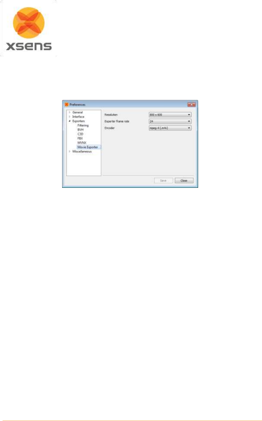
Document MV0319P.N
© Xsens Technologies B.V.
MVN User Manual
85
12.6 Export Movie
Exporting movie data enables the user to export the 3D viewport of MVN Studio to either .m4v or .avi.
this facilitates presenting MVN information to audiences without the need for installation of MVN Studio,
Select the export format, resolution and export frame in >Options >Preferences >Exporters >Movie
Exporter.

Document MV0319P.N
© Xsens Technologies B.V.
MVN User Manual
86
13 Features of MVN Studio
A range of additional features become available when using another license for MVN Studio PRO.
These are summarized in Table 6.
Table 6: Overview of features for each possible MVN Studio license
Features
MVN Studio
MVN Studio Pro
MVN Studio BIOMECH
Multi-person
Network Streamer (plug-ins)
Extended Network Streamer
Limited configurations
All
All
Limited scenarios
All
All
Reference camera support
Export as movie
Time code & remote control
Graphs
Real-time graphs
Extended MVNX
Third party synchronization
Display biomechanical model

Document MV0319P.N
© Xsens Technologies B.V.
MVN User Manual
87
13.1 Plug-ins
MVN Studio PRO and MVN Studio BIOMECH are equipped with the following plug-ins:
MVN Time Code and Remote Control Plug-in
The MVN time code and remote control plug-in is designed in case synchronization of single or multiple
MVN systems with other systems is required. The data of a MVN system is time stamped during
recording, so it can be lined up afterwards with data of other systems i.e. cameras, audio, etc. In a set-
up with multiple MVN systems the plug-in allows you to start and stop the recording of multiple MVN
systems as well as other third party devices via remote commands.
Additionally, the following plug-ins not installed with MVN Studio are downloadable from the web:
MVN MotionBuilder or Maya Live Plug-in
These plug-ins allow data recorded in MVN Studio to be streamed in real-time to an animation scene in
Autodesk’s Motion Builder or Maya.
Unity 3D
MVN Unity Live Plug-in is a module that gives Unity developers access to MVN motion capture data
allowing artists and developers to easily view live motions in real-time on character. The plug-in supports
scaled skeleton data for multiple characters.
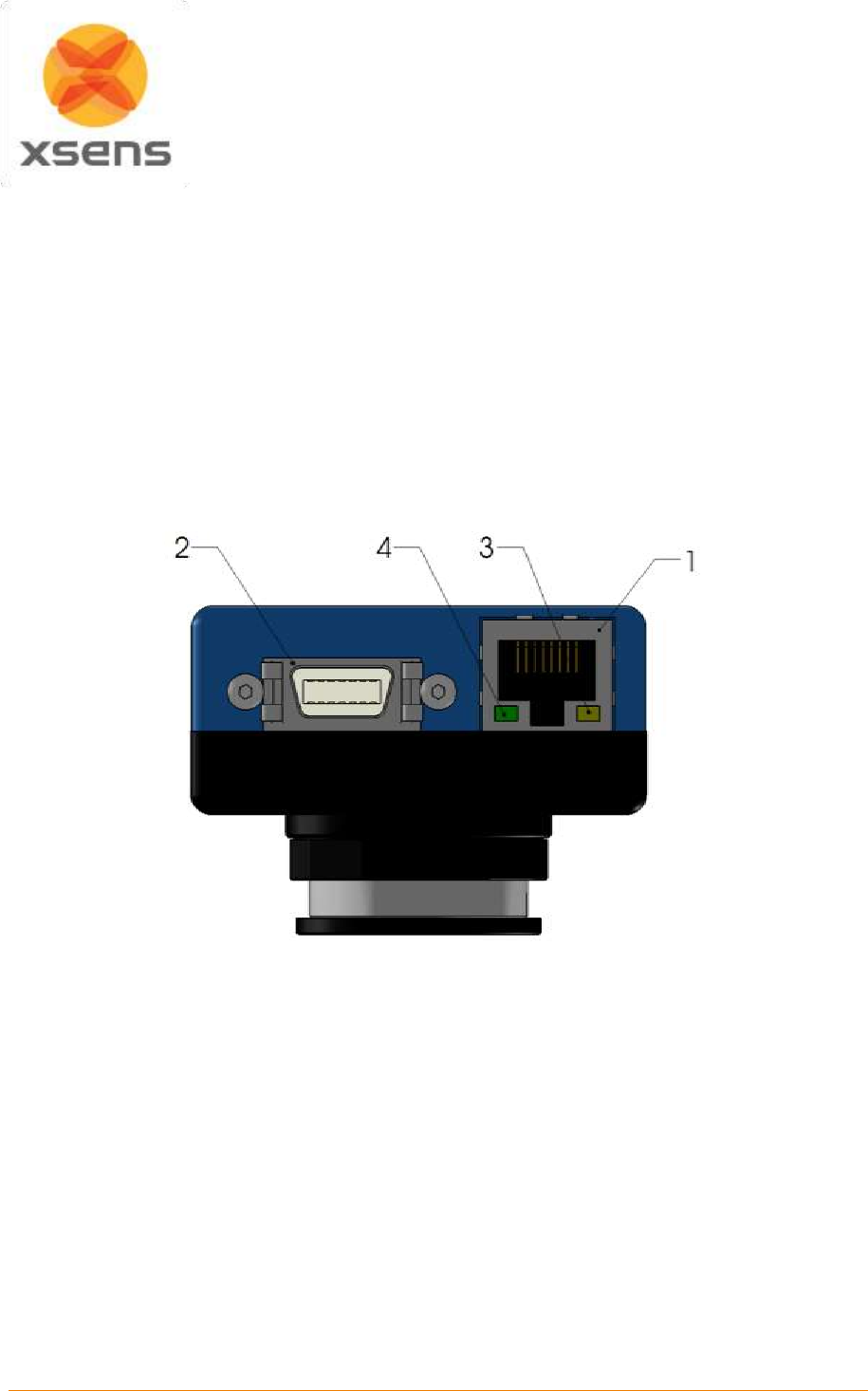
Document MV0319P.N
© Xsens Technologies B.V.
MVN User Manual
88
14 MVN Ethernet Camera
MVN Studio 3.0 has the ability to record synchronized MVN and video data. This is possible using the
Ethernet camera (Prosilica GS650) provided with the PRO system. The camera is a high quality
professional GigE camera with a C mount. The GigE interface enables the use of long cables (max
100m) and standard 1 Gigabit Ethernet cards for interfacing. The currently supported frame rate in MVN
Studio is limited, but the camera itself is capable of 120 frames per second (fps), depending on lighting
conditions. The camera has a global shutter and is capable of advanced triggering and synchronization
features.
14.1 Using the MVN camera GS650
The MVN camera GS650 has the following components, which you will need to know to connect to your
PC.
Figure 60: Interface and connections drawing of the MVN camera GS650.
1. Gigabit Ethernet interface, IEEE 802.3 1000BASE-T conformant, CAT5E or CAT6 recommended,
max 100m.
2. GPIO port – Power supply
3. Status LED 1
a) Solid Orange, link established
b) Flashing Orange, data transmission, activity
4. Status LED 2
a) Solid Green, normal operation
b) Flashing, 1 Hz, booting
c) Flashing, 3x quickly @ 1 Hz, error
To use the MVN Camera, connect the power supply to the mains power (Slot 2 of Figure 60) and connect
the network cable (Slot 1 of Figure 60) to the MVN Camera and to the network slot of the PC or laptop.

Document MV0319P.N
© Xsens Technologies B.V.
MVN User Manual
89
14.2 Camera driver
The camera should be available to MVN Studio when connected. The camera driver is installed together
with the software. However, depending on your network card specification and the setup used, in some
cases MVN Studio does not find the camera, or the performance is not as expected, re-installing the
driver may solve this issue.
A dedicated driver (Prosilica GigE Filter Installer 1.20.exe) is available and can be found in folder
...\Program Files (x86)\Allied Vision Technologies\
14.3 Network Configuration
There are two main methods of connecting the camera to your PC/laptop. There is also a third method,
which is possible, but not recommended.
1. Connect the MVN Camera directly to the LAN-port on your PC/laptop.
2. The most advanced and recommended way of connecting the camera to your PC/laptop is to
equip it with a second Ethernet-card. This way you can keep a wired LAN connection with your
(corporate) network and receive the camera data directly on your PC/laptop without being routed
over the LAN.
3. Connect the MVN Camera to the same LAN your PC/laptop is connected to (in your building).
The data will then be routed via the LAN/switch to your PC/laptop.
The MVN camera is configured to obtain its IP-address by DHCP. In both cases the camera must be
able to obtain an IP-address via a DHCP service. In the case you connect the camera directly to your
PC the operating system must issue a (private) IP-address to the camera, this should happen
automatically in Windows. Most LAN networks are configured to provide a DHCP service, ask your
network administrator for details if you encounter any problems.
A direct connection (options 1 and 2) is faster, more robust and prone to less potential latency and
connection issues.
Note that in the case that your PC/laptop has another means of accessing the LAN/internet, such
as a WiFi link it is actually quite easy to opt for choice 1 or 2, with the advantages of a direct, fast
connection to the camera, while still being connected to the LAN/internet.
Option 3 is not recommended, since this way of connection will not support high frame rates. However,
a connection via the LAN has the advantage of having access to the services on the LAN (e.g. internet).
Additionally, depending on the (security) policies implemented on the LAN it might be difficult in getting
things to work without support from your network administrator. Technically, the DHCP service must
give the camera an IP-address and subnet in the same range as the PC/laptop.
14.4 Jumbo Frames
The MVN camera will work with any Gigabit Ethernet network card; however it is strongly recommended
that Gigabit Ethernet components that support Jumbo Frames are used.
A Jumbo Frame is loosely defined as a frame size greater than 1500 bytes however typical Jumbo
Frames are around 9000 bytes. Frame size is the number of bytes per packet and the larger the frame
size, the less the computer CPU will be loaded due to the processing of incoming packets. There are
many Gigabit Ethernet cards available which will support Jumbo Frames. The following examples have
been verified to work well with the camera:
Intel PRO/1000
D-Link DGE-550T
SMC EZ Card 1000
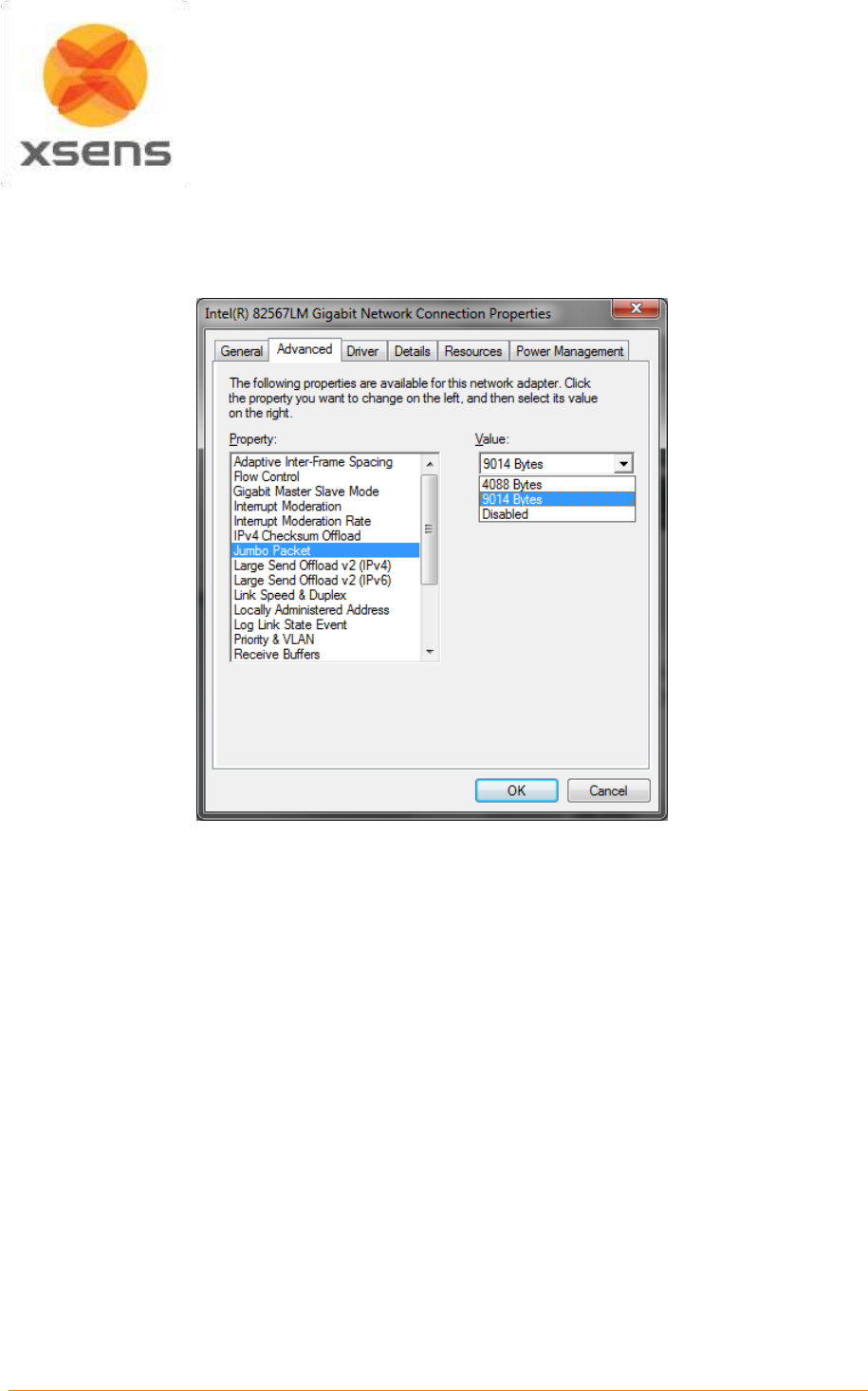
Document MV0319P.N
© Xsens Technologies B.V.
MVN User Manual
90
Please check the Ethernet Network Card settings in the Windows Device Manager to enable support for
“Jumbo Frames” and adjust it to its maximum value. The “Jumbo Frames” might also be called
“Maximum Frame Size”.
Figure 61: Screenshot illustrating setting the correct Jumbo Frame settings in the Device Manager
dialogue.
14.5 Camera Usage Guidelines
Do not remove the fitted lens, this may cause the camera to become out of focus and may introduce dirt
and debris in the housing destroying the CCD sensor in the camera. If you need to fit a different lens,
this is done outside of warranty and on your own risk.
Document MV0319P.N
© Xsens Technologies B.V.
MVN User Manual
91
15 Xsens Peripheral Software
15.1 Magnetic Field Mapper (MFM)
When a motion tracker is mounted to an object that contains ferromagnetic materials, the measured
(Earth) magnetic field can become distorted, causing errors in measured orientation. To correct for
known magnetic disturbances, for example, an MT attached to a steel prosthesis or prop, or simply that
the magnetic field has become distorted due to an event or over time, a separate software product has
been developed to allow users to remap the magnetic field. This software is called Magnetic Field
Mapper (MFM).
If MFM is needed, users should contact support@xsens.com for further support.
15.2 Firmware Updater
With new software releases, it can be expected that new firmware is required. For this purpose, Xsens
supplies a firmware updater which can be downloaded separately from MVN Studio at
https://www.xsens.com/mvn-studio-download/.
15.3 Software Activation Tool: Offline License Activation or Updating a License
An offline activation can be performed with the Software Activation Tool. In the offline activation process
a Customer-to-Vendor (c2v) file is generated containing information on the current status of the licenses
in your Sentinel protection keys. You can then send this file in order to activate license or receive a
license update.
NOTE: If you are using a dongle you must connect the dongle, before performing either of the following
procedures.
15.3.1 Step 1: Retrieve the license information from a Sentinel protection key
1. Launch the Software Activation tool from the start menu or help menu in MVN Studio
2. Click “Show advanced options”.
3. Activating a Software License key for the first time: ensure that “Installation of a New Protection
Key” is selected at the bottom of the screen. Updating an existing key or activate a dongle: ensure
that “Update of existing protection key” is selected at the bottom of the screen.
4. Click “Create security key information file (C2V)”
5. Click “Next”, the file is generated
6. Specify the directory where you want to store the C2V file. Enter a file name and click “Save”.
7. The C2V file for the Sentinel protection key is generated and saved in the required location. The file
can now be sent.
15.3.2 Step 2: Send the C2V file
1. Send the C2V file to Xsens support (support@xsens.com) requesting an offline license file.
2. You will receive a Vendor-to-Customer file (v2c) from Xsens support.
15.3.3 Step 3: Apply the received v2c file using the Software Activation tool.
1. Launch the Software Activation tool.
2. Click “Show advanced options”.
3. Click “Apply license file (V2C)”.
4. Click “Next” and browse to the V2C files you have received to open it
The license is activated/updated.

Document MV0319P.N
© Xsens Technologies B.V.
MVN User Manual
92
15.4 Software Activation Tool: Applying an Update
You can use the Software Activation tool to apply an update to the licenses stored in your Sentinel
protection keys.
To update the licenses in the Sentinel protection keys:
1. Launch the Software Activation tool from the start menu or help menu in MVN Studio
2. Click “Show advanced options”.
3. Click “Apply license file (V2C)”.
4. Click “Next” and browse to the V2C files you have received to open it
The license is activated/updated.
15.5 RUS Utility: Rehosting a Sentinel protection key
The RUS utility can be downloaded from: https://www.xsens.com/mvn-studio-download/
You can use the RUS utility to transfer a Sentinel protection key from one computer (the source
computer) to another (the recipient computer). This is a three-step procedure that uses the RUS utility
on both computers.
15.5.1 Step 1: Collect Information about the Recipient Computer
1. On the recipient computer, launch the RUS utility
2. Click the Transfer License tab.
3. Follow the instructions labelled “Step 1” to collect information about the computer and save it to a
file. Make sure that the file (or a copy of the file) is accessible on the source computer.
15.5.2 Step 2: Generate the License Transfer File
1. On the source computer, launch the RUS utility
2. Click the Transfer License tab.
3. Follow the instructions labelled “Step 2” to select the SL key to transfer, read the recipient
information file, and generate a license transfer (h2h) file. Make sure that the license transfer file (or
a copy of the file) is accessible on the recipient computer.
Note: After you perform this step, the SL key is no longer available on the source computer. Be sure to
keep a copy of the transfer file until you have completed the transfer procedure.
15.5.3 Step 3: Apply the License Transfer File
1. On the recipient computer, in the RUS utility, click the Apply License File tab.
2. In the Update File field, click the browse button and locate the license transfer (h2h) file.
3. Click Apply Update. The SL key is installed on the recipient computer.
NOTE: To ensure the success of the transfer procedure, all the steps in the procedure should be
completed within no more than a two days of the time you first start the process.
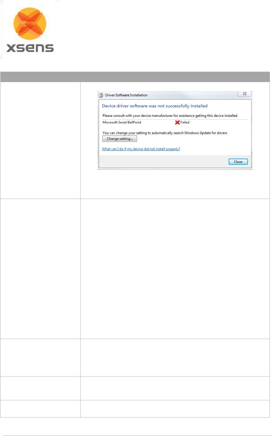
Document MV0319P.N
© Xsens Technologies B.V.
MVN User Manual
93
16 Troubleshoot
Problem
Solution
Device driver error
Awinda Station with docked
MTw’s results in "Driver
Software Installation" error.
See figure to the right
displaying the pop-up
warning:
This is a timing issue because Xsens motion trackers send data to the
PC continuously to guarantee a fast set up time. To solve, remove the
tracker from the station then redock.
The suit does not connect.
Check battery levels.
Check ‘Hardware status’ menu (Section 7.8).
Check Suit configuration (Section 7.2.11)
Ensure that only one MVN Studio is running on a given computer.
MVN LINK:
Turn on the BP off and on again (Section 5.5.5).
Run a WPS between BP and AP
MVN Awinda:
Unplug Awinda Station from power supply and PC then reconnect re-
plug.
Power off MTws press power button for 6s. Press for 1s to turn back
on.
MTx status remains missing
(‘red’) in ‘Hardware status’
menu
Check if MTx is connected. Sometimes a connector can become loose
after putting on the suit.
Replace MTx and relocate sensor ID (Section 7.8.1).
MVN Studio does not start
(Shader compilation /
validation errors).
Use a computer with at least a DirectX 9 hardware card.
Limited range wireless
connection
Turn off all other wireless equipment (Bluetooth, WiFi, etc) and scan
for a WiFi channel free of other wireless signals.
Document MV0319P.N
© Xsens Technologies B.V.
MVN User Manual
94
Problem
Solution
Live preview is active but
recording is not possible
Enter the subject dimensions: body height and foot size (Section 8.1).
Perform an N-pose calibration (Section 8.2.2). Make sure to apply.
MVN Awinda:
Make sure that no Synchronization settings have been saved to the
Awinda station
Directly after the T-pose
calibration, the axes of
rotation of the subject do not
correspond with 3D
character.
Place MT on the pelvis flat on the sacral bone with Z axis pointing away
from subject.
Magnetic field is too disturbed at calibration. Use the ‘Show Magnetic
Disturbance’ option in the preview window to find a proper location (no
red spots in 3D viewport) (Section 19.2.1).
Character sticks to the
ground or segments are
pulled apart (wrongly
detected contacts).
Enter correct body dimensions of subject (Section 8.1).
Perform new calibration pose.
Choose suitable user scenario (default is flat ground assumption)
(Section 7.2.12).
Make sure the feet trackers are mounted rigidly.
Character appears to
bounce slightly when no
movement is taking place.
This is likely to be caused by visualization rather than data issues.Can
result when tile size on the floor in MVN Studio is large.
Verify that the character is not moving using position data (eg graphical
representation) to ensure that no movement is being detected. The
position data should remain unchanged.
When this is the case, make the tile size smaller, usually 50cm is a
good tile size for visualization. To do this, go to >Options >Preferences
>Interface > 3D View
Shadows have jerky
movements, even when
character remains
unmoving.
Visualization issue, probably caused by floor tile size being too large,
meaning that the shadow is redrawn too frequently. Decrease the size
of the tiles to reduce this visualization effect.
Pelvis is displayed too high.
MVN file is recorded with old version of MVN Studio. Make a copy of
the original file and reprocess (Section 10.3.2.7).
Pelvis is displayed too low.
Use MVN Studio v2.0 or higher to play the MVN file.
The system does not run in
real-time.
Close all other running application.
Check wireless connection (maximum range and disable other
wireless equipment).
Reduce the display frame rate and/or update rate.
Document MV0319P.N
© Xsens Technologies B.V.
MVN User Manual
95
Problem
Solution
See Section 19.13 for the specification of the recommended computer
system.
During recording, the
rotations of some segments
do not correspond with the
3D character.
Check if MT’s have not moved in the suit. Perform a new calibration.
Move calmly for 10-20 seconds directly after calibration.
Check for magnetic disturbance (Section 19.2).
Stand still and perform a Character Reset (Ctrl+Alt+F).
During recording, the
rotations of some segments
are not smooth.
Check wireless connection.
Sensors clipped. Use ‘Correct sensor clipping data on reprocess’
option in >Options >Preferences >General >Recordings. Reprocess
file.
Check for magnetic field disturbance (Section 19.2).
Stand still and perform a Character Reset (Ctrl+Alt+F).
With MVN Awinda:
Change the radio channel (See 19.12.1)
Verify that this is also the case with a saved and reprocessed file
(which will also contain retransmitted data)
Graphical performance of
MVN Studio is poor; update
of image is slow
Set display frame rate to the same rate as the update rate in the
preferences menu.
Avatar/ system drops from
MVN Studio
This may be due to network configurations. Uninstall the network driver
for the active Ethernet connection (through your device manager) then
reinstall.
With MVN Awinda
there appears to be a large
latency
Change the radio channel. (See 19.12.1)
MTw LED shows
dual blink pattern
This does not happen often, if it does it means that the MTw has
crashed. To restore to normal, switch it off, by pressing the button for
6s. Press it for 1s to turn it back on.
When connecting 2
or more MVN Awinda
systems, MTw’s assign to
the wrong awinda station
Begin by connecting one Awinda station and turn on the MTw’s for the
system associated with this receiver. Select the system under
Accepted Systems and change the Wifi Radio channel in the Hardware
Status window to allow all of the MTw’s to connect.
Once the system is detected, repeat this process with the second and
additional systems.
Document MV0319P.N
© Xsens Technologies B.V.
MVN User Manual
96
Problem
Solution
Character walks in
place or is seen flying
across the screen
Check to make sure that all trackers are in the correct locations
The battery from one
MTw tracker drains much
faster than the other
trackers
Contact support www.xsens.com/support for assistance.
MVN Studio fails to connect
with suit. Error code #40
Contact support www.xsens.com/support for assistance.

Document MV0319P.N
© Xsens Technologies B.V.
MVN User Manual
97
17 Warranty and liability
Xsens Technologies B.V. warrants the products manufactured by it to be free from defects in material
and workmanship for a period of 2 years from the date of delivery. Products not subjected to misuse will
be repaired, replaced or credit issued at the sole option of Xsens Technologies B.V. Contact support:
www.xsens.com/support for return material authorization (RMA) prior to returning any items for
calibration, repair or exchange. The product must be returned in its original packaging to prevent
damage during shipping.
The warranty shall not apply to products repaired or altered or removed from the original casing by
others than Xsens Technologies B.V. so as, in Xsens Technologies B.V. opinion, to have adversely
affected the product, products subjected to negligence, accidents or damaged by circumstances beyond
Xsens Technologies B.V.’s control.
NOTE: Xsens reserves the right to make changes in its products in order to improve design,
performance, or reliability.
Subject to the conditions and limitations on liability stated herein, Xsens warrants that the Product as so
delivered shall materially conform to Xsens’ then current specifications for the Product, for a period of
one year from the date of delivery. ANY LIABILITY OF XSENS WITH RESPECT TO THE SYSTEM OR
THE PERFORMANCE THEREOF UNDER ANY WARRANTY, NEGLIGENCE, STRICT LIABILITY OR
OTHER THEORY WILL BE LIMITED EXCLUSIVELY TO PRODUCT REPAIR, REPLACEMENT OR, IF
REPLACEMENT IS INADEQUATE AS A REMEDY OR, IN XSENS' OPINION IMPRACTICAL, TO
REFUND THE PRICE PAID FOR THE PRODUCT. XSENS DOES NOT WARRANT, GUARANTEE, OR
MAKE ANY REPRESENTATIONS REGARDING THE USE, OR THE RESULTS OF THE USE, OF THE
PRODUCT OR WRITTEN MATERIALS IN TERMS OF CORRECTNESS, ACCURACY, RELIABILITY,
OR OTHERWISE. Xsens shall have no liability for delays or failures beyond its reasonable control.
17.1 Customer Support
Xsens Technologies B.V. is glad to help you with any questions you may have about MVN or about the
use of the technology for your application. Please contact Xsens Customer Support:
by e-mail: www.xsens.com/support
telephone: Xsens HQ +31 88 97367 00 / Xsens US office 310-481-1800
To be able to help you, please mention the 8-digit number on the Xsens Sticker, you can find this at the
handle of the Suitcase or backpack.

Document MV0319P.N
© Xsens Technologies B.V.
MVN User Manual
98
18 Regulatory Notices MVN Awinda
18.1 Radio Frequency Exposure and Emission
The MTw2, Awinda dongle and station contains a small radio transmitter and receiver. During
communication with the Awinda Master it receives and transmits radio frequency (RF) electromagnetic
fields (microwaves) in the frequency range 2400 of 2500 MHz. The output power of the radio
transmitter is very low. When using the system, you will be exposed to some of the transmitted RF
energy. This exposure is well below the prescribed limits in all national and international RF safety
standards and regulations.
Most modern electronic equipment, for example, in hospitals and cars, is shielded from RF energy.
However, certain electronic equipment is not. Therefore:
Note: This equipment emits RF energy in the ISM (Industrial, Scientific and Medical) band. Please
insure that all medical devices used in proximity to this device meet appropriate susceptibility
specifications for this type of RF energy (CE or FCC marked).
Turn off this electronic device before entering an area with potentially explosive atmosphere. It is very
rare, but any electronic device could generate sparks. Sparks in such areas could cause an explosion
or fire resulting in bodily injury or even death. Areas with a potentially explosive atmosphere are often,
but not always, clearly marked. They include fuelling areas, such as petrol station, below deck on boats,
fuel or chemical transfer or storage facilities, and areas where the air contains chemicals or particles,
such as grain, dust, or metal powders.
18.2 FCC Statements
This equipment has been tested and found to comply with the limits for a Class B digital device, pursuant
to Part 15 of the FCC Rules. These limits are designed to provide reasonable protection against harmful
interference in a residential installation. This equipment generates, uses and can radiate radio frequency
energy and, if not installed and used in accordance with the instructions, may cause harmful interference
to radio communications. However, there is no guarantee that interference will not occur in a particular
installation. If this equipment does cause harmful interference to radio or television reception, which can
be determined by turning the equipment off and on, the user is encouraged to try to correct the
interference by one of the following measures:
Reorient or relocate the receiving antenna.
Increase the separation between the equipment and receiver.
Connect the equipment into an outlet on a circuit different from that to which the receiver is
connected.
Consult the dealer or an experienced radio/TV technician for help.
FCC Caution: Any changes or modifications not expressly approved by the party responsible for
compliance could void the user's authority to operate this equipment.
This device complies with Part 15 of the FCC Rules. Operation is subject to the following two conditions:
(1) This device may not cause harmful interference, and (2) this device must accept any interference
received, including interference that may cause undesired operation.

Document MV0319P.N
© Xsens Technologies B.V.
MVN User Manual
99
Radiation Exposure Statement for Awinda Station:
This equipment complies with FCC radiation exposure limits set forth for an uncontrolled environment.
This equipment should be installed and operated with minimum distance 20cm between the radiator &
your body.
This transmitter must not be co-located or operating in conjunction with any other antenna or transmitter.
This MVN Awinda product contains
FCC ID: MTw2: QILMTW2-3A7G6
Awinda Station: QILAW-A2
Awinda Dongle: QILAW-DNG2
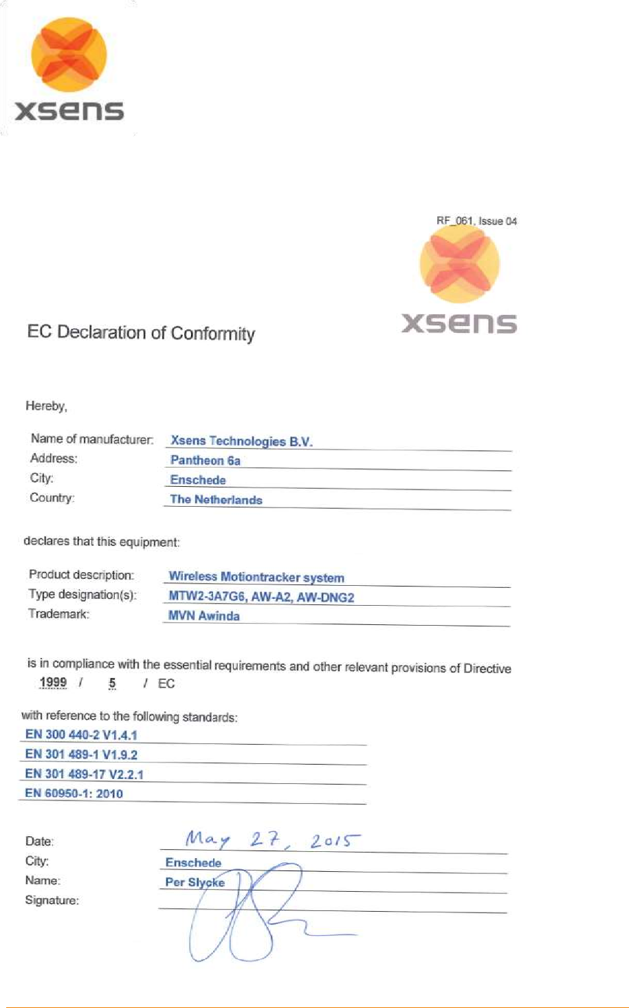
Document MV0319P.N
© Xsens Technologies B.V.
MVN User Manual
100
18.3 Declaration of Conformity
18.3.1 CE Declaration of Conformity MTw2, Awinda Station, Awinda Dongle

Document MV0319P.N
© Xsens Technologies B.V.
MVN User Manual
101
18.3.2 FCC Declaration of Conformity MTw2

Document MV0319P.N
© Xsens Technologies B.V.
MVN User Manual
102
18.3.3 FCC Declaration of Conformity Awinda Station

Document MV0319P.N
© Xsens Technologies B.V.
MVN User Manual
103
18.3.4 FCC Declaration of Conformity Awinda Dongle
Document MV0319P.N
© Xsens Technologies B.V.
MVN User Manual
104
19 Appendices
19.1 Lycra suit sizes overview
Table 7 is an overview of the typical height and weight of a subject that will fit into a given suit size.
While this is generally accurate, it is an indication, therefore test the suit size, to ensure that it is tight
enough to keep MTx’s in place during measurement while remaining relatively comfortable.
Table 7: MVN Lycra Suit sizes
Size
Body height
Weight
S
1.55 - 1.65 cm
5'1'' - 5'4'' ft.
50 – 65 kg
110 – 143 lbs.
M
1.65 - 1.70 cm
5'4'' - 5'6'' ft.
65 – 75 kg
143 – 165 lbs.
L
1.70 - 1.80 cm
5'6'' - 5'9'' ft.
75 – 85 kg
165 – 187 lbs.
XL
1.80 - 1.95 cm
5'9'' - 6'4'' ft.
85 – 95 kg
187 – 210 lbs.
XXL
Up
Up
Up
Up
19.2 Magnetic Disturbances
A common problem with inertial and magnetic sensing is the presence of large ferromagnetic objects
which may distort the detected magnetic field and change the perceived global north. MVN Studio has
a few functionalities built in, which can be used to prevent magnetic disturbance from disturbing
measurements. These features include the ability to view magnetic field distortion on the 3D animated
character. This is available live and on a recorded file. Additionally, on a recorded file, the magnetic field
can be seen graphically, or exported in the MVNX file for further checks.
19.2.1 Show magnetic disturbance
To determine the most appropriate location for your experiments or evaluate unexpected performance,
visualize disturbances in the magnetic field. Magnetic field properties are visualized by circles around
the hands, pelvis and feet in the ‘Preview & Recording’ window, at calibration stage (see Figure 62).
Most unknown disturbances are usually present in the floor (iron reinforced concrete structures), for this
reason, during the preview and recording stage, only the magnetic indicators at the feet are shown.
The color of the circle is a measure of the magnitude of the disturbance. The magnitude is based on
average magnetic field properties (such as the strength and dip angle) of all MT’s. There are three
indictor colors:
Green: the magnetic field at the MT is suitable to perform a calibration
Yellow: the magnetic field is disturbed, if possible look for another location
Red: the magnetic field is too disturbed to perform a calibration
The spheres can be switched on or off by clicking the show/hide magnetic disturbances icon.
Choose whether or not to always show or hide the magnetic disturbance indicators at >Options
>Preferences >Interface >Character >Display magnetic disturbances.
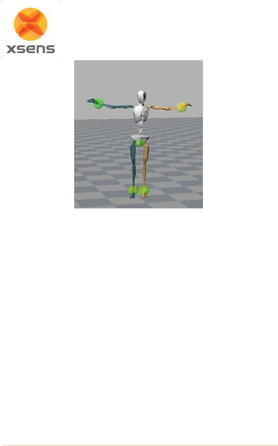
Document MV0319P.N
© Xsens Technologies B.V.
MVN User Manual
105
Figure 62: Show magnetic disturbances
In Figure 62, the MT on the left hand shows a warning and is probably close to a wall or an iron object.
The rest of the circles are green which indicates that the magnetic field is suitable to perform a
calibration. The advice is to move to a different location in such way that the red circle becomes yellow
or (preferably) green.
When some circles are green and some are yellow or red, try to find a spot in the room or building where
the red circles disappear. When the red circles around the feet remain at all locations, you can step onto
an object to gain some distance from the floor (e.g. you can use the MVN suit case) and perform a
calibration. After the calibration you can then step on to the floor and work there for quite some time
before performance degrades. When all circles are red and remain red when walking around, the room
or building is not suitable for capturing with MVN. This is extremely rare. Try to use another location if
possible.
When a circle turns red for a short period; it indicates that the field is locally disturbed. The MVN Fusion
Engine offers a high grade of rejection against temporary disturbances and you can continue with
recording without worrying.
19.2.2 Magnetic Norm
Since MVN Studio 3.1.5, it has been possible to view the magnetic field norm in the graphs. This is
found in > Sensor data > Magnetic Field and is represented by the black line in the graph.
Magnetic norm facilitates the finding of a magnetically sound environment needed for calibrations and
preferred for measurements.
Note: Mag Field Norm is not an exported value. However it can be calculated as follows:
Mag Field Norm = squareroot (xˆ2 +yˆ2 + zˆ2)
The following figures and explanations show how best to use the Magnetic Field Norm data in a practical
situation. The upper graph of both Figure 63 and Figure 64 is the head, and the lower graph is of the
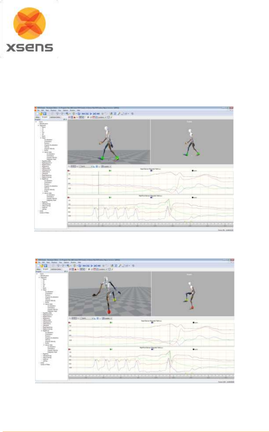
Document MV0319P.N
© Xsens Technologies B.V.
MVN User Manual
106
right foot. The lower graph coincides with the colored indicators in the 3D and orthogonal views of MVN
Studio, when the magnet icon is active.
As Figure 63 shows, the magnetic field indicators are green; this is represented as a line close to zero
in the Mag Field Norm plots shown for the head and the right foot. This shows that the magnetic field is
sound for measuring.
Figure 63: Mag Field Norm coincides with green Mag Field indicators. Top graph is Mag Field of the MT on
the Head. Bottom graph is MT on the Right Foot.
:
Figure 64: Mag Field Norm coinciding with red Mag Field indicators. Top graph is Mag Field of the MT on
the Head. Bottom graph is MT on the Right Foot.

Document MV0319P.N
© Xsens Technologies B.V.
MVN User Manual
107
From the same recording, Figure 64 shows that when the subject has moved, they have approached a
ferromagnetic material. This is known because the Mag Field Norm increases, in particular for the right
foot, as it increases above 1.5. If this value increases further and remains high for longer than a few 30
seconds (usually less than 2 can be dealt with in the algorithms used in MVN Studio) then this area
should be avoided, in particular during calibrations, but if possible, also during measurements.
19.3 MVN kinematics and output
19.3.1 Quaternion orientation representation
A unit quaternion vector can be interpreted to represent a rotation about a unit vector n through an angle
.
22
cos , sin
GBq
n
A unit quaternion itself has unit magnitude, and can be written in the following vector format:
0 1 2 3
, , , ,q q q q q
1q
Quaternions are an efficient, non-singular description of 3D orientation and a quaternion is unique up to
sign:
qq
An alternative representation of a quaternion is as a vector with a complex part, the real component is
the first element .
The inverse
BGq
is defined by the complex conjugate * of :
*
0 1 2 3
, , ,
GB BG
q q q q q q
As defined here,
GBq
rotates a vector
Bx
in the body co-ordinate system (B) to the global reference co-
ordinate system (G).
*G GB B GB GB B BG
q q q q x x x
Where
represents a quaternion multiplication:
0
1 2 1 2 1 2, 1 2 2 1 1 2
0 0 0
q q = q q v v q v q v v v
with:
1 2 3
1 2 3
1 1 , 1 , 1
2 2 , 2 , 2
v q q q
v q q q
and both
and
represent the standard dot and cross product, respectively. Be aware that the order
of multiplication is important. Quaternion multiplication is not commutative, meaning:
1 2 2 1q q q q
19.3.2 Conversions
Quaternion to rotation matrix:
0
q
GBq
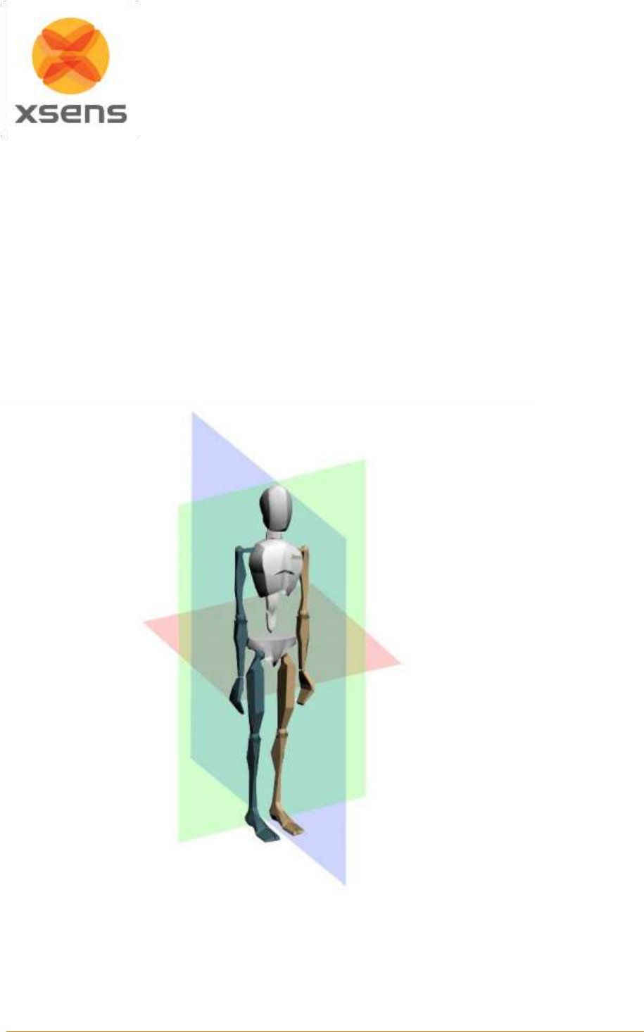
Document MV0319P.N
© Xsens Technologies B.V.
MVN User Manual
108
2 2 2 2
0 1 2 3 1 2 0 3 1 3 0 2
2 2 2 2
1 2 0 3 0 1 2 3 2 3 0 1
2 2 2 2
1 3 0 2 2 3 0 1 0 1 2 3
22
2 3 1 2 0 3 1 3 0 2
22
1 2 0 3 1 3 2 3 0 1
1 3 0
2 2 2 2
2 2 2 2
2 2 2 2
1 2 2 2 2 2 2
2 2 1 2 2 2 2
22
q q q q q q q q q q q q
q q q q q q q q q q q q
q q q q q q q q q q q q
q q q q q q q q q q
q q q q q q q q q q
q q q q
R=
22
2 2 3 0 1 1 2
2 2 1 2 2q q q q q q
For further information on quaternion operations and rotations, refer to the book: J.B. Kuipers.
Quaternions and Rotation Sequences. Princeton University.
19.4 Body planes
Figure 65: Body planes
19.5 Coordinate systems
The MVN Fusion Engine calculates the position and orientation, and other kinematic data of each body
segment, B, with respect to an earth-fixed reference co-ordinate system, G. By default the earth-fixed
reference co-ordinate system used is defined as a right handed Cartesian co-ordinate system with:
Frontal / coronal plane
Transverse plane
Sagittal plane

Document MV0319P.N
© Xsens Technologies B.V.
MVN User Manual
109
Global reference frame:
X positive when pointing to the local magnetic North (red).
Y according to right handed co-ordinates (West) (green).
Z positive when pointing up (blue).
Local coordinate frame:
Body: segments in anatomical pose:
Origin: center of rotation (proximal)
X forward.
Y up, from joint to joint.
Z pointing right.
This difference in coordinate systems will not affect results.
After the calibration procedure, the right heel of the character is set at the origin (0,0,0). This is the begin
point of the red arrow in the 3D viewport (pointing in the positive X-direction).
The orientation output is represented using quaternions. The definition of the segment co-ordinate
system can be found in Section 19.6. Joint origins are determined by the anatomical frame and are
defined in the center of the functional axes with the directions of the X, Y and Z being related to functional
movements. For example, flexion/extension of the knee is described by the rotation about the BZ-axis of
the lower leg with respect to the upper leg; abduction/adduction is the rotation about the BX-axis; and
endo/exo rotation is about the BY-axis. Note that in some studies, different anatomical and reference
frames definitions are used; to compare results proper co-ordinate frame transformations must be
performed.
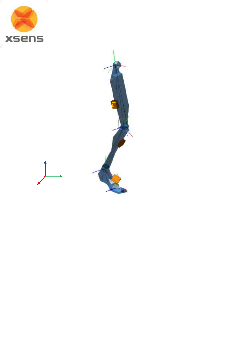
Document MV0319P.N
© Xsens Technologies B.V.
MVN User Manual
110
Figure 66: Global and local coordinate frames in MVN Studio
19.6 Anatomical model
19.6.1 Definition of segment axes
To describe motion capture data in clinically meaningful data, e.g. joint rotations, it is necessary to define
a coordinate reference frame attached to the body segment. The ISB proposal for standardization for
joint coordinate systems is currently based on positions (optical markers) of bony landmarks. For most
segments on the body, the origin of the reference frame and direction of axes are described in Wu and
Cavanagh (1995) [
i
] Wu et al. (2002) [
ii
] and Wu et al. (2005) [
iii
].The MVN Fusion Engine uses the
calibration poses to determine the direction of the axes of each segment. Figure 67a shows the origins
of the segment axes in the neutral anatomical pose. The origin of the segment is always in the proximal
joint center which is the functional rotation point. The origin is chosen such that by connecting all joint
centers a character (skeleton) is formed, see Figure 67b. Their positions for the calibration poses in the
global reference frame can be found in the <segments>section and <frame type=”tpose/npose”>when
exporting as MVNX file.
Segment
A
Segment
B
Sensor
BYA
BXA
BZA
BXB
BYC
BZB
SXA
SYA
Body frame
Sensor frame
GZ
GX
GY
Global frame
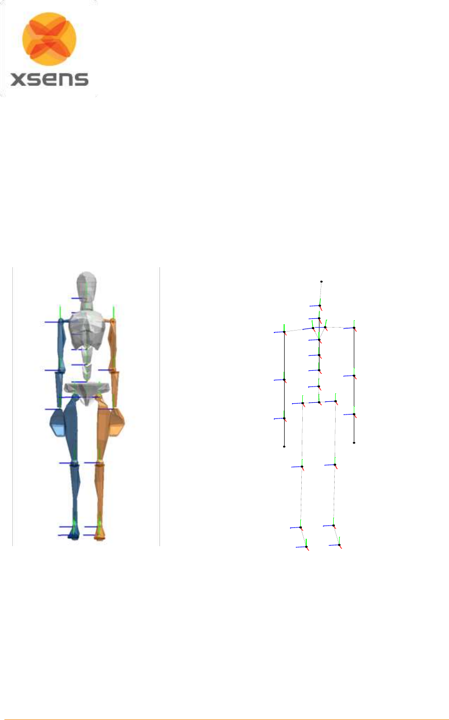
Document MV0319P.N
© Xsens Technologies B.V.
MVN User Manual
111
19.6.2 Bony/anatomical landmarks
The positions of bony/anatomical landmarks with respect to the joint origin of the related segment are
presented in the MVNX file, see the <points>tag in the <segment>section. Segments are assumed to
be rigid bodies.
Positions of anatomical landmarks in the global frame (G) can be found by rotating the vector of the
landmark in the body frame (B) to the global frame and adding the global position of the origin.
*G G GB B GB
landmark origin + q q p p x
Or in rotation matrix formulation:
G G GB B
landmark origin +p p R x
The rotation from body to global (GBq) and global position of the origin (Gpos) are given in the MVNX file,
see next section.
a
b
Figure 67: a) Segment coordinate system at each joint origin, as is used in MVN. b) Joint centers
connected, forming a skeleton Legend: x: red, y: green, z: blue
Note that positions of anatomical landmarks are not measured directly as they are with optical
measurement systems. They are computed using the measured accelerations, angular velocities and
rotations in combination with the biomechanical model. Relevant points are used for the detection of
contacts with the external world and as an indication for scaling of segment lengths.
The MVN character mesh (only for visualization) is an abstract representation of the human skeleton;
therefore not all anatomical landmarks are exactly on the mesh. The ribcage is connected to T8 and will
move accordingly.
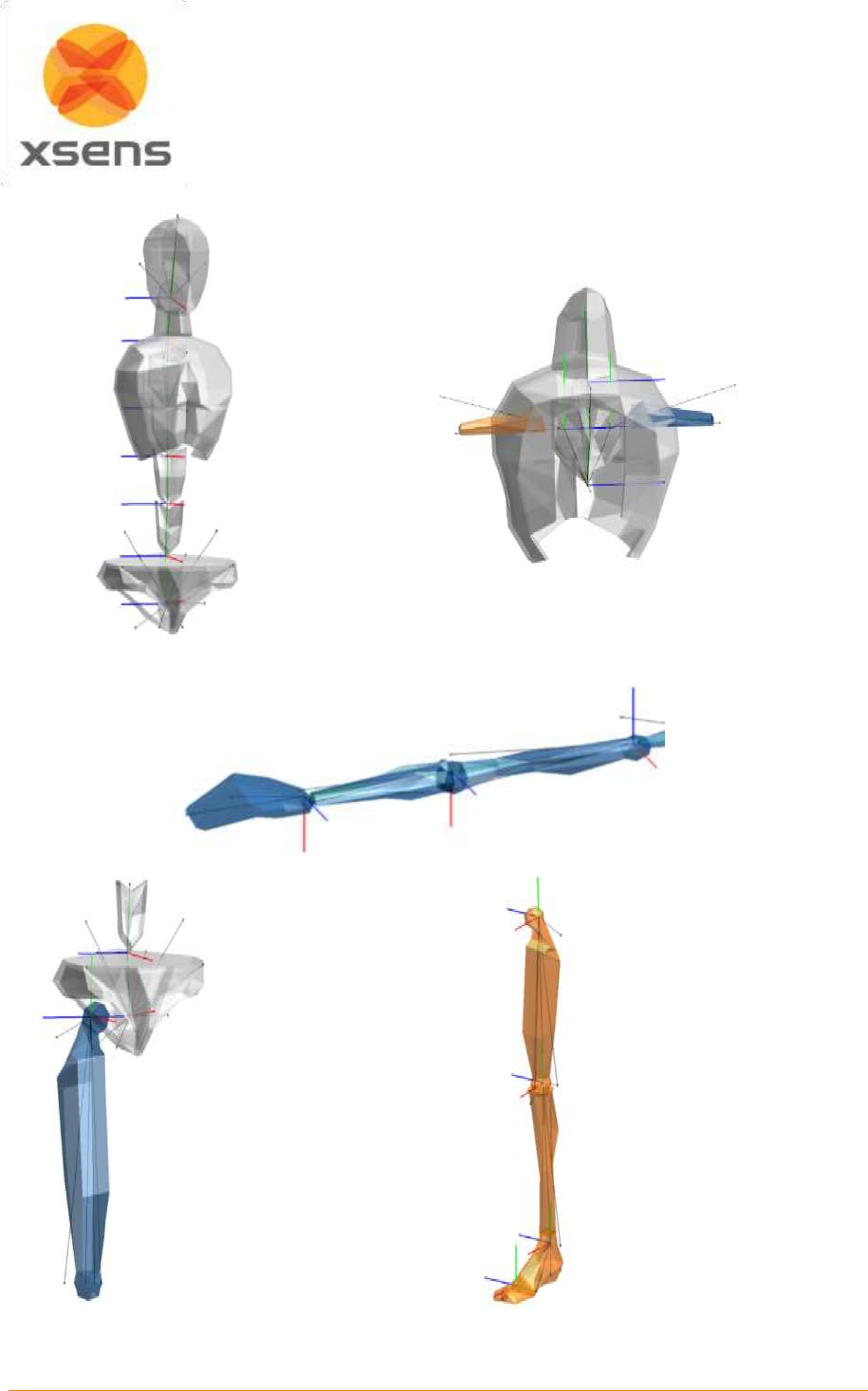
Document MV0319P.N
© Xsens Technologies B.V.
MVN User Manual
112
T8, ribcage,
neck and
shoulders
Right arm and shoulder
Upper body
Pelvis, L5 and
right upper leg
Left leg and
foot
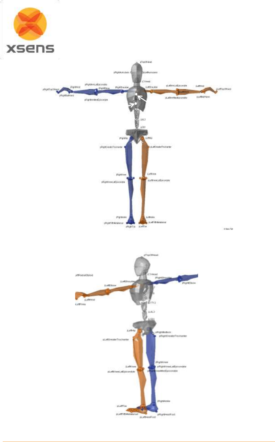
Document MV0319P.N
© Xsens Technologies B.V.
MVN User Manual
113
Figure 68: Selection of anatomical landmarks. Above, anterior view. Below, posterior view.
pPIJ
pPX
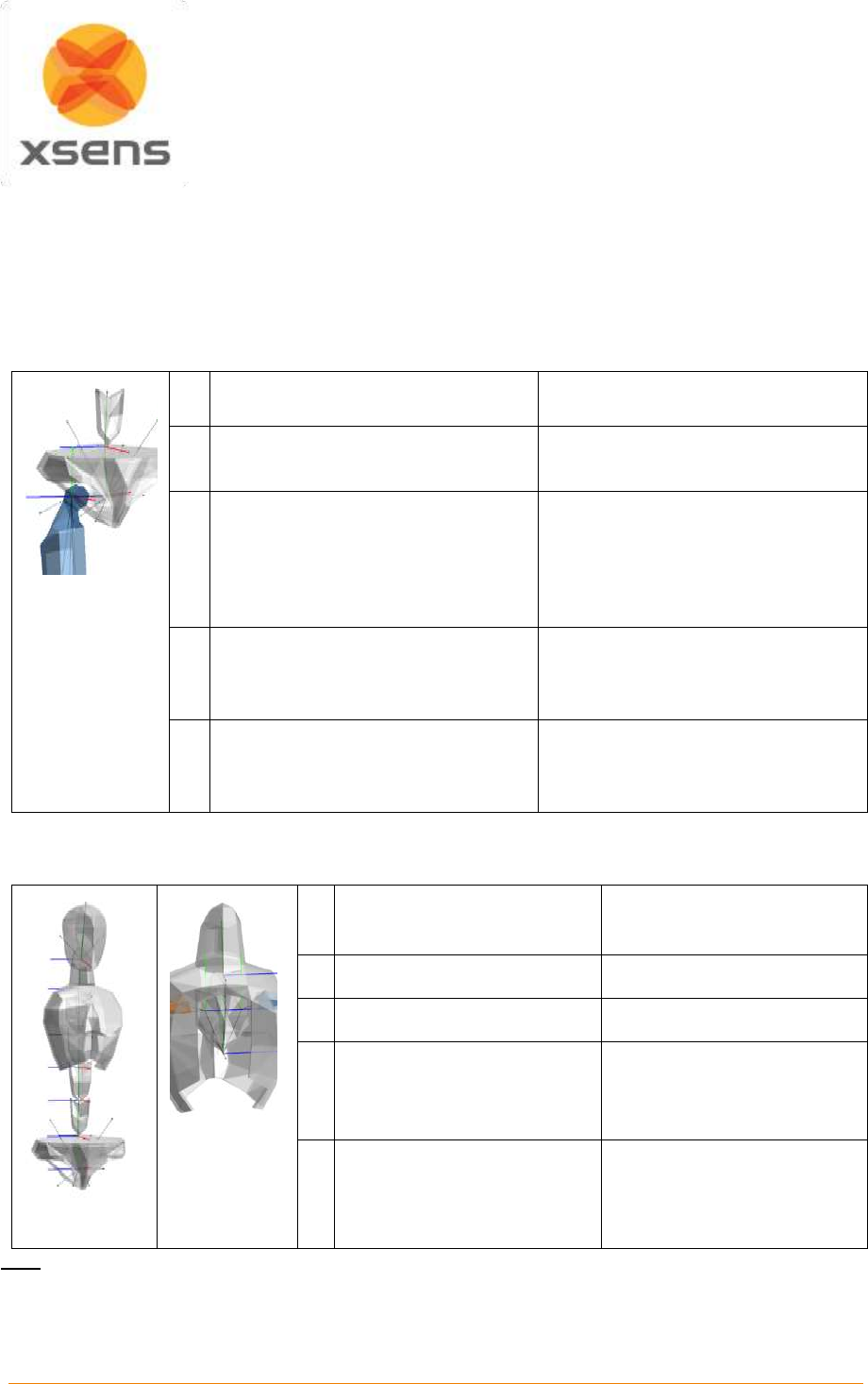
Document MV0319P.N
© Xsens Technologies B.V.
MVN User Manual
114
19.7 Segment axes definitions and Origin Definitions
Note: To ease comparison between the MVN segment co-ordinate systems with the International
Society of Biomechanics recommendation, currently based on optical position tracking systems, the ISB
recommendation is presented next to the MVN definition.
The MVN segment axes definition and origins have been chosen as closely as possible to the ISB
recommendation where whenever possible.
MVN
ISB [ii]
O
Midpoint between right and left hip
center of rotation
Coincident with hip center of rotation
X
Perpendicular to Y and Z
Pointing forward
Line parallel to a line lying in the
plane defined by two ASISs and
midpoint of two PSIS, orthogonal to
Z-axis.
Pointing anteriorly.
Y
hipOrigin to jL5S1
Pointing up
Line perp. to X and Z.
Pointing cranially. (Della Croce et
al.[iv])
Z
to jLeftHip to jRightHip
Pointing right
Line parallel to a line connecting
right and left ASISs.
Pointing right.
NB: Della Croce et al. [iv] define O as the midpoint between RASIS and LASIS
19.7.1 Spinal segments: L5, L3, T12, T8: Segments 2-5
MVN
ISB [ii]
O
jL5S1, jL4L3, jL1T12, jT9T8
X
Pointing forward
Line per. Y and Z
Y
Joint to Joint
Pointing up
Line passing thru centers of
vertebra’s upper and lower
endplates
Z
Perp. to X and Y
Pointing right
Line parallel to a line joining
similar landmarks on the
bases and right and left
pedicles
Note: Spine segments not measured directly in MVN, they are interpolated between the MT’s of the
Pelvis, Sternum and Head using a model of the spine. Joint origins are the rotation points in the
vertebrae.
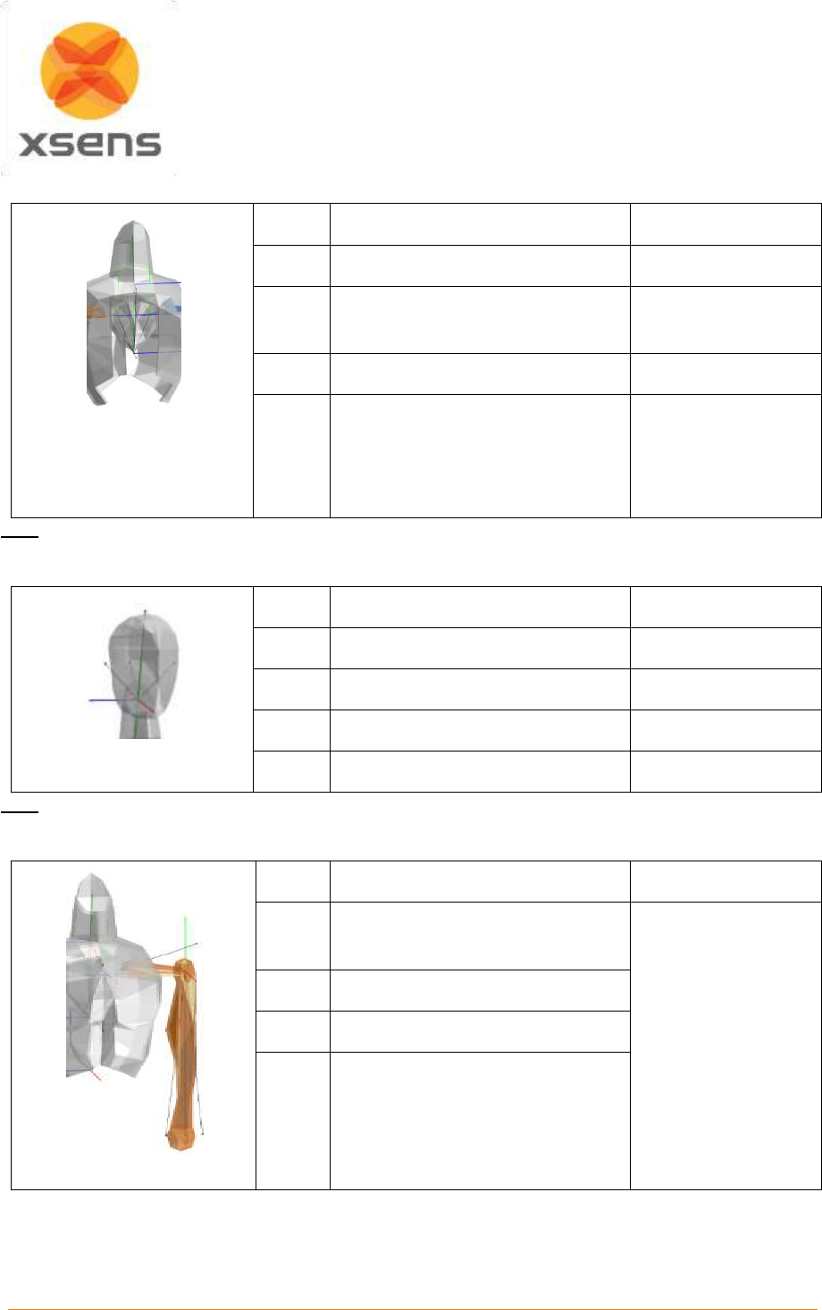
Document MV0319P.N
© Xsens Technologies B.V.
MVN User Manual
115
19.7.2 Neck: Segment 6
MVN
ISB
O
jT1C7
Not described in ISB
X
Perp. to Y and Z
Pointing forward
Y
jT1C7 to jC1Head
Z
Pointing right
Note: The neck segment is not measured directly in MVN; it is calculated using a model of the neck.
19.7.3 Head: Segment 7
MVN
ISB
O
jC1Head
Not described in ISB
X
Perp. to Y and Z
Y
jC1Head to TopOfHead
Z
Left Ear to Right Ear
Note: Position of Ears are not measured but assumed to be on the same height.
19.7.4 Shoulder: Segment 8 Right and Segment 12 Left
MVN
ISB
O
jRightC7Shoulder
jLeftC7Shoulder
See Wu et al. [iii] and
Šenk et al.v for range
of definitions.
X
Pointing forward
Y
Perp. to X and Z
Z
Right: jRightC7Shoulder to
jRightShoulder to
Left: jLeftC7Shoulder to jLeftC7
In ISB the shoulder complex is described with the Thorax, Clavicle, Scapula and Humerus. MVN does
not define the thorax segment. The thorax region is split into spine segments. The mesh of the thorax
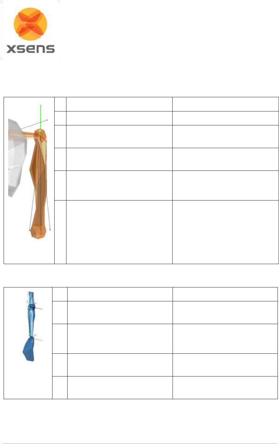
Document MV0319P.N
© Xsens Technologies B.V.
MVN User Manual
116
will move with segment T8 which is measured with the MT of the sternum. MVN does not measure the
clavicle and is undefined in MVN.
19.7.5 Upper Arm (Humerus): Segment 9 Right and Segment 13 Left
There are two segment coordinate systems described in ISB. The system described below is option 1.
MVN
ISB [iii]
O
jRightUpperArm GH
jLeftUpperArm GH
GH
X
Sagittal plane
Pointing forward
Line perp. Plane EL-EM-GH
Pointing forward
Y
Right: jRightElbow to jRightShoulder
Left: jLeftElbow to jLeftShoulder
Line connecting GH to mid point EL-
EM
Pointing to GH
Z
Perp. to X and Y
Pointing to the right
Line perp. Y and Z
Pointing to the right
19.7.6 Forearm (Radius/Ulna): Segment 10 Right and Segment 14 Left
There are two segment coordinate system described in ISB. Option 1 is described here.
MVN
ISB [iii]
O
jRightElbow
jLeftElbow
US
X
Pointing forward
Line Perp. plane thru US-RS and
midpoint EL-EM
Pointing forward
Y
Right: jRightWrist to jRightElbow
Left: jLeftWrist to jLeftElbow
Line connecting GH to mid point EL-
EM
Z
Perp. to X and Y
Pointing right
Line perp. X and Y
Note: The joint origin is the midpoint between the epicondyles in MVN.
In the anatomical pose, the hand and forearm are orientated forward
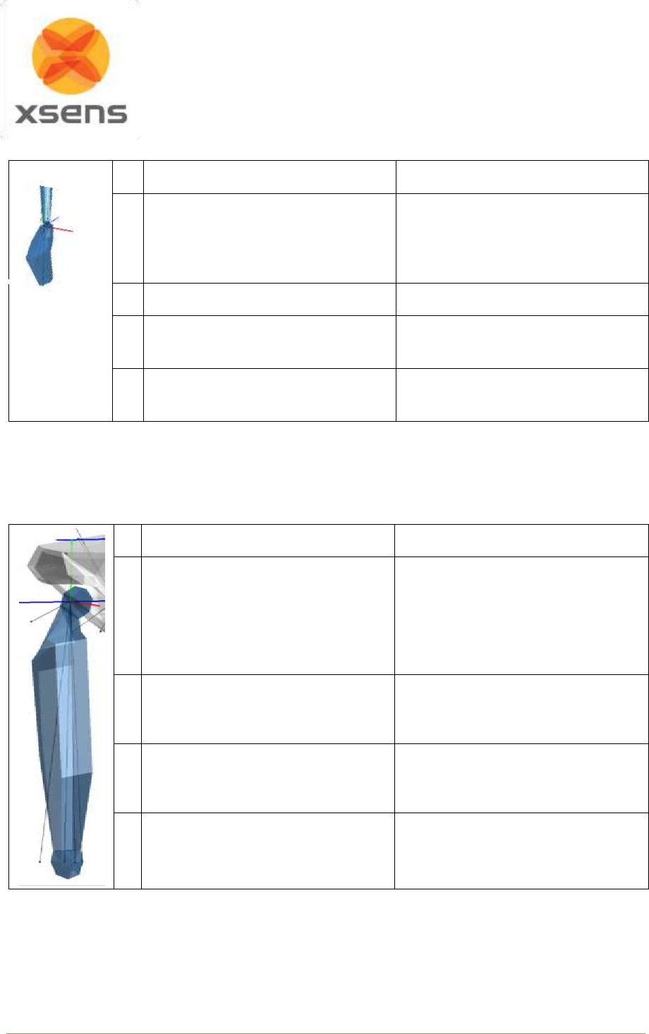
Document MV0319P.N
© Xsens Technologies B.V.
MVN User Manual
117
19.7.7 Hand: Segment 11 Right and Segment 15 Left
MVN
ISB [iii]
O
jRightWrist
jLeftWrist
ISB defines origins and axes for
each:
Of the 5 Metacarpals
14 phalanges
X
Pointing forward
Y
Top of Hand to jRightWrist/jLeftWrist
Pointing Vertical
Z
Perp. to X and Y
Pointing right
Note: In MVN, the joint center is the midpoint between the styloids.
No metacarpals are measured in MVN.
This description is for the anatomical pose. When the subject stands in the N-pose, X will no longer point
anteriorly, but medially.
19.7.8 Upper Leg (Femur): Segment 16 Right and Segment 20 Left
MVN
ISB [ii]
O
jRightHip/jLeftHip
(Only defined for use of calculating
the hip joint angle):
Coincident with right (or left) hip
center of rotation, coincident with
pelvic center O in neutral
configuration
X
Perpendicular to Y and Z
Pointing forward in sagittal plane
Line perp. to Y- and x-
Pointing anteriorly. (Della Croce et
al. [iv])
Y
Right: jRightKnee to jRightHip
Left: jLeftKnee to jLeftHip
Line joining midpoint between medial
and lateral Fes and the origin.
Pointing cranially
Z
Right: Medial to Lateral
Left: Lateral to Medial
Pointing right
Line perp. to Y-axis lying in plane
defined by origin and two Fes.
Pointing Right.
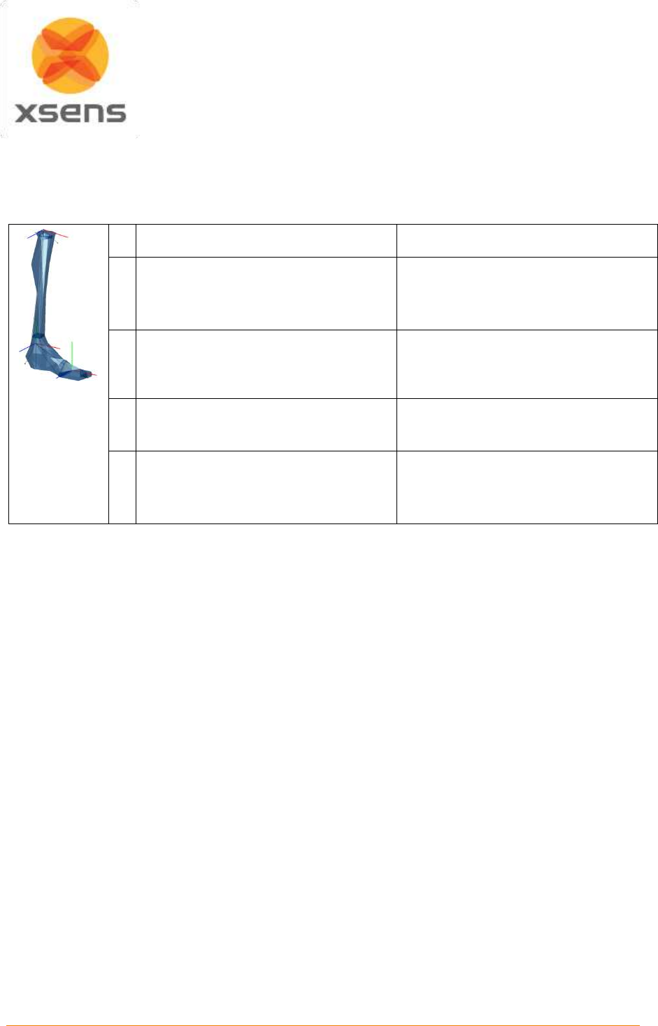
Document MV0319P.N
© Xsens Technologies B.V.
MVN User Manual
118
Note: In ISB and MVN, the origin is in center of hip rotation, which is the head of the femur. Della
Croce [iv]: midpoint LE and ME. In the MVN model, the lateral and medial epicondyles are on the same
height.
19.7.9 Lower Leg (Tibia/Fibula): Segment 17 Right and Segment 21 Left
MVN
ISB [ii]
O
jRightKnee
jLeftKnee
IM
IM
X
Perp. Y and Z
Pointing forwards
Line perp. to torsional plane of
tibia/fibula.
Pointing anteriorly
Y
Right: jRightAnkle to jRightKnee
Left: jLeftAnkle to jLeftKnee
Line perp. to X and Z
Z
Right: Medial to Lateral
Left: Lateral to Medial
Pointing right
Line between MM and LM.
Pointing to the right
Note: In MVN, the joint center is approx. between LC and MC which corresponds with the center of
rotation of the lower leg. Same coordinate system as Della Croce [iv], except that the origin is not in IM.
In ISB, the Y axis is not along the Tibia. In the MVN model the lateral and medial epicondyles and lateral
and medial malleoli are the same height.
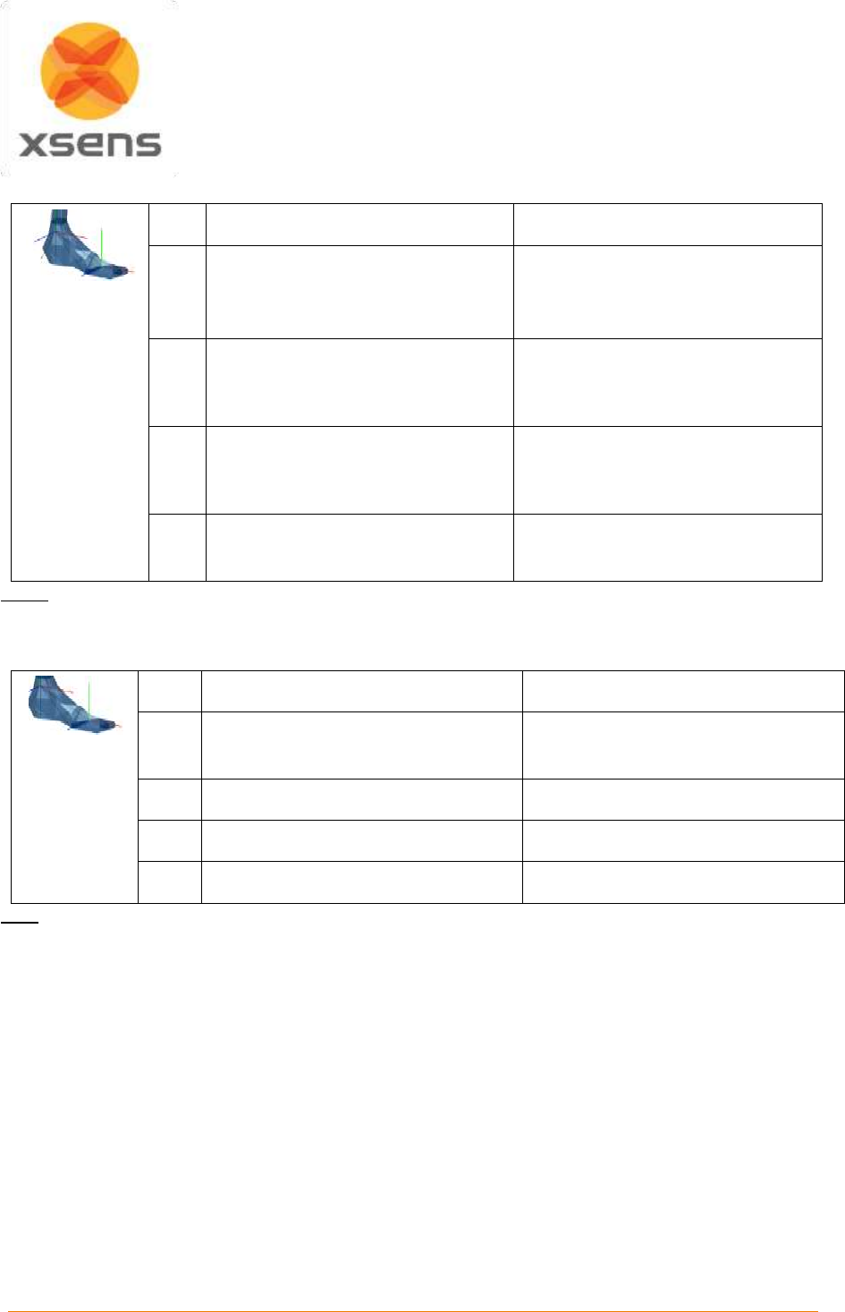
Document MV0319P.N
© Xsens Technologies B.V.
MVN User Manual
119
19.7.10 Foot (Calcaneus): Segment 18 Right and Segment 22 Left
MVN
ISB [ii]
O
jRightAnkle
jLeftAnkle
IM
IM
X
Sagittal plane forward
Line perp. to frontal plane of tib/fib
in neutral configuration.
Pointing anteriorly.
Y
Vertical (aligned with gravity,
pointing up)
Line coincident with long axis of
tibia/fibula, in neutral configuration.
Pointing cranially
Z
Perp. to X and Y
Pointing right
Line perp. to x- and Y-
Note: In the MVN model lateral and medial malleoli are on the same height.
19.7.11 Toe: Segment 19 Right and Segment 23 Left
The toes are not defined in ISB.
MVN
ISB
O
jRightToe
jLeftToe
The toes are not defined in ISB.
X
Sagittal plane forward
Y
Vertical (aligned with gravity)
Z
Perp. to X and Y
Note: In MVN toes are not measured directly but are based on the foot kinematics and contact detection.
The origin is between the metatarsals of the foot. Toes can only flex and extend, other kinematics are
due to interpolation.
19.8 Joint angles
Typically, a joint rotation is defined as the orientation of a distal segment
B
GB q
with respect to a proximal
segment :
A B A B
B B GB GB
*
q= q q
where
denotes a quaternion multiplication and
*
the complex conjugate of the quaternion (see
Section 19.3.1). There are a few commonly used parameterizations of the joint rotation
AB
BBq
that
describe joint angles:
the Cardan/Euler representation [Cole 1993, Woltring 1994]
joint coordinate system [Grood & Suntay 1983]
vi
helical angle [Kinzel 1972]
A
GB q

Document MV0319P.N
© Xsens Technologies B.V.
MVN User Manual
120
Note that all representations of the joint angles are based on the same quaternion or rotation matrix.
The differences lie only in how the angles are extracted (represented) from this rotation. The
International Society of Biomechanics (ISB) has proposed standards for rotation sequences for the lower
[Wu et al, 2002ii] and upper body [Wu et al 2005iii].
19.8.1 Euler Extractions for the joint angles
In order to produce validated joint angle output, Xsens MVN works closely to the ISB and Grood and
Suntay recommendations [i,ii,iii,vi]. Almost all angles follow the ISB Euler angle extractions of Z
(flexion/extension), X (abduction/adduction) Y (internal/external rotation). The definitions of the origins
of the segments are somewhat different, since MVN uses MT’s placed on the segment, rather than
markers placed on bony landmarks. The origins and coordination axes are defined above.
19.8.2 Shoulder angle definitions
For joint angle calculations, the only difference for Euler extractions between MVN and ISB is for the
shoulder joint. MVN provides three different shoulder angle calculations, as can be seen in the data tree,
after a session has been recorded.
The shoulder joint angles provided are:
Angles between C7 and the shoulder segment
Euler rotation sequence ZXY
Euler rotation sequence XZY
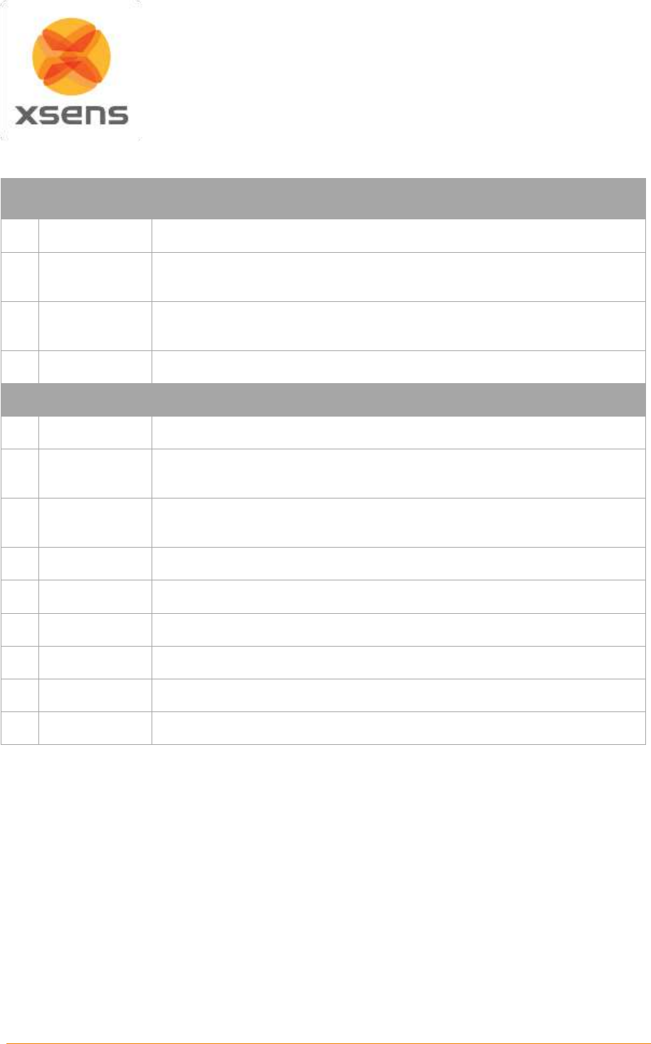
Document MV0319P.N
© Xsens Technologies B.V.
MVN User Manual
121
19.8.3 Joint angle outputs
Below is an overview of all joints available in MVN and a short description.
Joint Angle
(Tree name)
Description (& Euler Sequence)
1
L5S1
Joint between the lumbar spine segment 5 and sacral spine 1 (ZXY)
2
L4L3
Joint between the lumbar spine segment 4 and lumbar spine segment 3
(ZXY)
3
L1T12
Joint between the lumbar spine segment 1 and thoracic spine segment 12
(ZXY)
4
C1Head
Joint between the cervical spine segment 1 and the head segment (ZXY)
Left and Right
5
C7Shoulder
Joint between cervical spine 7 and the MVN shoulder segment
6
Shoulder ZXY
Shoulder joint angle between the MVN shoulder segment and the upper
arm; calculated using the Euler sequence ZXY
7
Shoulder XZY
Shoulder joint angle between the MVN shoulder segment and the upper
arm; calculated using the Euler sequence XZY
8
Elbow
Joint between the upper arm and the forearm. (ZXY)
9
Wrist
Joint between the forearm and the hand. (ZXY)
10
Hip
Joint between the pelvis and upper leg. (ZXY)
11
Knee
Joint between the upper leg and lower leg. (ZXY)
12
Ankle
Joint between the lower leg and foot. (ZXY)
13
BallFoot
Joint between the foot and the calculated toe. (ZXY)

Document MV0319P.N
© Xsens Technologies B.V.
MVN User Manual
122
19.9 XKF-HM
Xsens Motion tracking works on the basis of Kalman Filtering. In its simplest form, it combines the
different information sources to calculate the desired parameters. This has an impact on how the
systems should be used. The more historically correct data has been measured (in good magnetic
environments for example and with enough physical movement of the motion trackers) the more robust
the filter can be. For this reason we advise to calibrate in a magnetically sound environment (See Section
3.4.1) and to “warm-up” the filters by moving casually for a short time, to build up this history (See below
for settling time details).
With MVN Studio 4.0 and onwards, Xsens has created a special filter dedicated to accurately measuring
human motion. This filter is called XKF-HM (Xsens Kalman Filter for Human Movement) and is based
on a number of assumptions that humans will move with varying degree of speed, high and low
accelerations, while assuming that the duration of accelerations will not be longer than is humanly
possible.
The XKF-HM filter works well in a variety of environments and dynamics. This means that measurements
can take place of movement that is semi-static up to high dynamics as well as being possible to stay in
magnetically challenging environments for longer. This has been made possible due to the improved
signal pipeline.
An important aspect of using any measurement apparatus is the scale of the sensor. Often, for example
with a temperature sensor (thermometer!) when the range is exceeded, the sensor either breaks or
simply can no longer measure outside of the defined range. With Xsens sensors, when the data exceeds
the limits there is a potential of this influencing the calculated orientation and could last more than a few
sample frames due to the history build up. However with the new algorithms this is completely prevented.
Clipping is of course possible, when the range of the component is exceeded. However, the influence
of this clipping is negligible. For the component itself, when the movement is back in range the
measurement continues as normal and the calculated orientation returns to an accurate state
immediately. It is also possible to observe when clipping occurred during recording, so that if this data
is required it can be ignored. Furthermore in future releases this will be possible to reprocess and will
have no effect (since both historical and future data are known in a recorded file).
Other remarks: Some amount of correction for the changing magnetic field is present in the new XKF,
this is due to three things: the improved signal pipeline mentioned above, a new model that is used for
modelling magnetic field behavior and compensation and that there is also some recalibration of the
magnetic field taking place in this algorithm. This means that when a new magnetic environment is
present, the filter understands that this is new and temporary and can compensate for this for a longer
time.
19.9.1 Height tracking
Due to the many improvements, from signal processing to how data is handled in MVN Studio including
foot contact detection, it is now possible to track height changes of a subject e.g. walking upstairs or up
a steep slope while wearing the system. Please note that height changes due to e.g. changing floor level
in an elevator will not be detected, since there is no relative change in motion of the body segments, in
this case, it will appear that the subject stands still and continues on a level plane.
19.9.2 XKF-HM Settling time
Settling time is the time needed for the filters to “warm up”. When they are warmed up, information like
gyroscope and magnetometer biases can be estimated and uncertainties minimized.
Tests have shown that the best practice for achieving a good settling time is to remain still for 30 seconds
after the initial calibration (N or T pose).

Document MV0319P.N
© Xsens Technologies B.V.
MVN User Manual
123
If a reset is required during measurements, it is also advised that the subject stands still when the reset
is enabled and remains still for 30 seconds thereafter. In these 30 seconds, the gyroscope biases are
estimated and the uncertainties minimized.
If there are issues regarding problematic magnetic field distortions follow the instructions below:
1. Configure the system (see section 7.1).
2. Move all motion trackers in smooth 3D, circular motions. This can be done with hardware
1. In the suitcase or rucksack, for approximately 3 minutes.
2. On the subject for approximately 6 minutes.
3. Perform a basic calibration (N or T pose).
4. Stand still for 30 seconds.
19.10 Update Rate versus Sample Frequency
Since MVN Studio 4.0, Xsens refers to the term “update rate” rather than sample frequency. This is an
intentional change in terminology since the data is sampled in a different way than in the past.
Normal, digital systems using some form of recording relies on sampling of this data. Since data is
sampled, this implies some degree of data loss at those time instances that no sampling took place.
Sampling must take place a measureable time, some amount of times over a given time frame. This is
known as the sampling frequency. Most systems operate at a given sample frequency.
The intentional difference in terminology is needed to highlight that data from new Xsens motion trackers
(MTx and MTw) undergoes a mathematical method called Strap Down Integration. This ensures that no
loss of accuracy is experienced, even though the data is transmitted to the PC at lower update rates.
Update rates as low as 20 or 30Hz still provides very accurate data.
19.11 Strap Down Integration
Strap down integration (SDI) is a method used to compute an orientation/position change given an
angular velocity and linear acceleration of a rigid body. Angular velocity and acceleration data in the
MTx and MTw is sampled at a very high frequency (1000Hz) to maintain accuracy under very dynamic
conditions such as vibrations and impacts. The sampling frequency is too high to be transmitted
wirelessly, and would typically present a computational load that is too high on the receiving host device
(e.g. PC). Therefore the data that has been sampled at a high frequency is digitally filtered and down-
sampled to 600 Hz and calibrated using the individual device calibration
7
values on the embedded
microprocessor (MCU) of the MTw. Based on this data the MTx and MTw further calculates velocity
increments and orientation increments using an SDI algorithm. The main advantage of using the SDI
algorithm is that full 3D tracking accuracy can be maintained even if the output update rate from the
MTx and MTw is lower (<100 Hz). An additional advantage is that the MTx and MTw can continue to
track the 3D motion internally when facing transient data loss in the RF transmission and immediately
report the full 3D velocity and orientation increment as soon as the RF link is restored, without the need
to re-transmit all the data that was lost which would a) cause a large delay during real-time tracking b)
use a lot of precious RF bandwidth and consume unnecessary power. The specific use of SDI data in
combination with such a specialized RF protocol, Xsens has named the Awinda protocol
8
.
19.12 The Awinda Protocol
The Awinda protocol is the wireless protocol that controls the data stream from the MTws to the Awinda
Station or Awinda Dongle. This wireless protocol provides accurate time synchronization of up to 32
7
The devices are calibrated at the factory by Xsens and is a highly sophisticated process compensating for
component errors that are not stochastic (i.e. they can be modeled). Compensation models include bias, gain,
misalignment, g sensitivity, temperature effects, etc.
8
Patents pending.
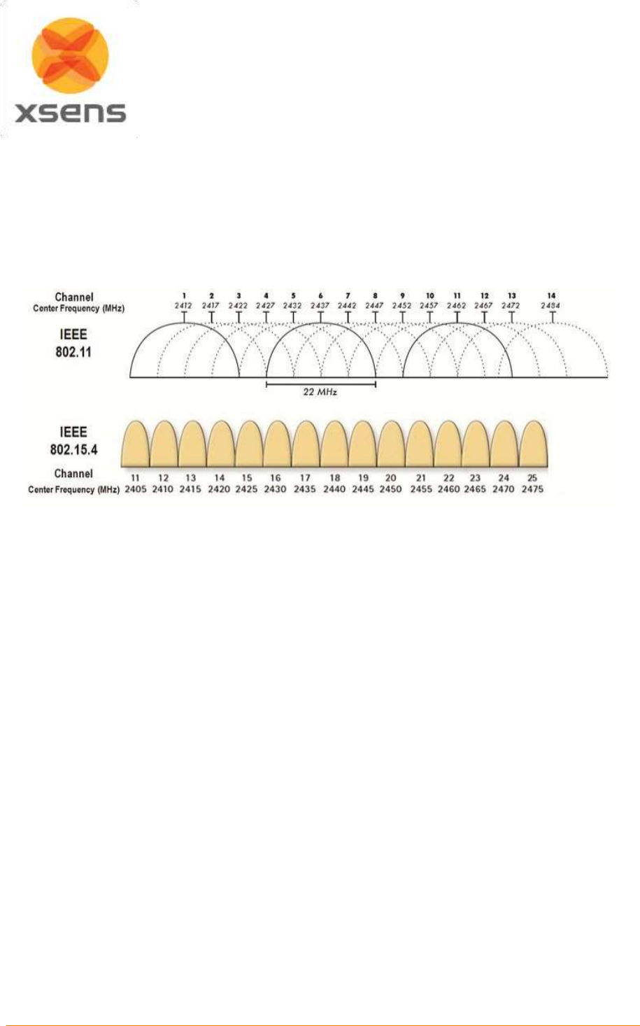
Document MV0319P.N
© Xsens Technologies B.V.
MVN User Manual
124
MTw's across the wireless network to within 10 microseconds, achieving 'wired like' system
performance. The Awinda protocol is developed such that no data is ever lost. If individual packets are
missed, there is some room to contain data temporarily. This buffered data is then retransmitted. If these
packets become lost (for example if the subject wearing the hardware is outside of the radio transmission
range and for a prolonged period – meaning the buffer becomes full) then it is still possible to retrace
the missing data due to the use of SDI. Retransmitted data is used during reprocessing, for this reason
Awinda data can appear better – smoother and more accurate after reprocessing.
19.12.1 Choosing a Radio Channel for MVN Awinda
Figure 69: Overview of channels operating around 2.4GHz; for ease of channel selection
Figure 69 provides an overview of the allowed channels for operating MVN Awinda. The Awinda protocol is based
on the IEEE 802.15.4, around 2.4 GHz. The bottom row of the figure shows the channels on the 2.4GHz, the top
row shows how WiFi channels use the spectrum. This should indicate to the user that the best channels to use
when you know which channel WiFi is on. When in an environment where WiFi is also expected to be in prevalent
use, but you are not sure which channels, try Channels 11, 15, 20 or 25. Bluetooth uses the entire spectrum
around 2.4 GHz, but will (try to) avoid channels in use by other systems including Awinda channels.

Document MV0319P.N
© Xsens Technologies B.V.
MVN User Manual
125
19.13 System Specifications
Recommended computer system
Operating system
Windows 7/8 (64 bit)
Processor
Quad core or higher (2.7 GHz or faster)
Hard drive
SSD 256 GB or more
Memory
8 GB RAM (64-bit)
Graphics card
Hardware acceleration for DirectX 11
Dedicated memory 512 MB or more
Network card
Gigabit Ethernet, support for jumbo frames (9014 Bytes)
USB ports
USB 2.0 (1 per MVN Awinda system, 1 per license dongle)
MVN System
Number of trackers per suit configuration:
Full body
17 inertial motion trackers
Extra prop /backup
1 inertial motion tracker
Optional extra trackers:
2 inertial motion trackers
MVN Camera
Prosilica GS650
MVN Mounting Straps
Fabrifoam with Velcro closure
Full body Lycra suit:
Light weight revolutionary stretch fabric with exterior zippered
channels for trackers and wires
Sizes:
Straps one size fits all, with 3 sizes of vests (s-m, m-l, l-xl).
Suit: S, M, L (standard), XL, XXL
Accessories:
2 gloves with tracker pocket
1 head band with tracker pocket
2 foot pads with Velcro patch
Pair of shorts (MVN Link)
MVN Link on body cabling:
1 cable connects Body Pack to Battery Back, all remaining
strings of trackers connect to Body Pack.
Data control units:
1 Body Pack
Power (BP)
Battery
rechargeable smart Lithium Ion battery pack
Power adapter (incl.)
EU/US/UK Power adapter 110-240VAC/12VDC 1A
Operating time (typical)
9.5 hours
Battery charger (included)
battery charger with ability to recalibrate
fuel gauge on battery packs
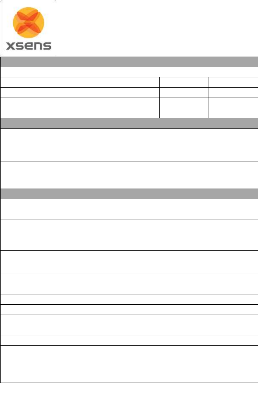
Document MV0319P.N
© Xsens Technologies B.V.
MVN User Manual
126
Communication
Interface
Wireless (WiFi or Awinda Protocol)
Wireless range radius (max)
MVN
Awinda Station
Awinda dongle
Outdoor
150 meter (492 ft.)
~50m (164 ft.)
~20m
Indoor open space
150 meter (492 ft.)
~20m ()
~10m
Indoor office
50 meter (164 ft.)
~20m ()
~10m
Wireless receiver units:
MVN Link
MVN Awinda
Number of Wireless Receivers
1 Access Point
1 Awinda Station or Awinda
Dongle
RF technology
WiFi 2.4GHz, 5.0 GHz
IEEE 802.15.4 PHY
2.4GHz
Interface
Ethernet
USB 1.1 or 2.0
Power
Battery
USB (station additionally
mains power supply)
Physical
Dimensions MTx
36 x 24.5 x 10mm
Dimensions BP
160 x 72.5 x 25 mm
Dimensions MTw
47 x 30 x 13 mm
Dimensions Awinda Station
148x104x61.9 mm
Dimensions Awinda Dongle
45x20.4x10 mm
Dimensions MVN suitcase
559 x 351 x 229 mm (22 x 13 x 9 inches)
Flight case with wheels & extendable handle.
Durable & watertight
Weight MTx
10 g
Weight BP
150 g
Weight MTw
16g
Weight Awinda Station
233g
Weight Awinda dongle
8g
Weight MVN Suit(no trackers)
485 g
Weight MVN Straps(no trackers)
153 g
Weight total on-body system
(with batteries and cables)
1130 g
MVN Awinda: 525 g
Shipping weight
10 kg
5.5 kg
Operation environment
0 – +50 deg Celsius, non-wet
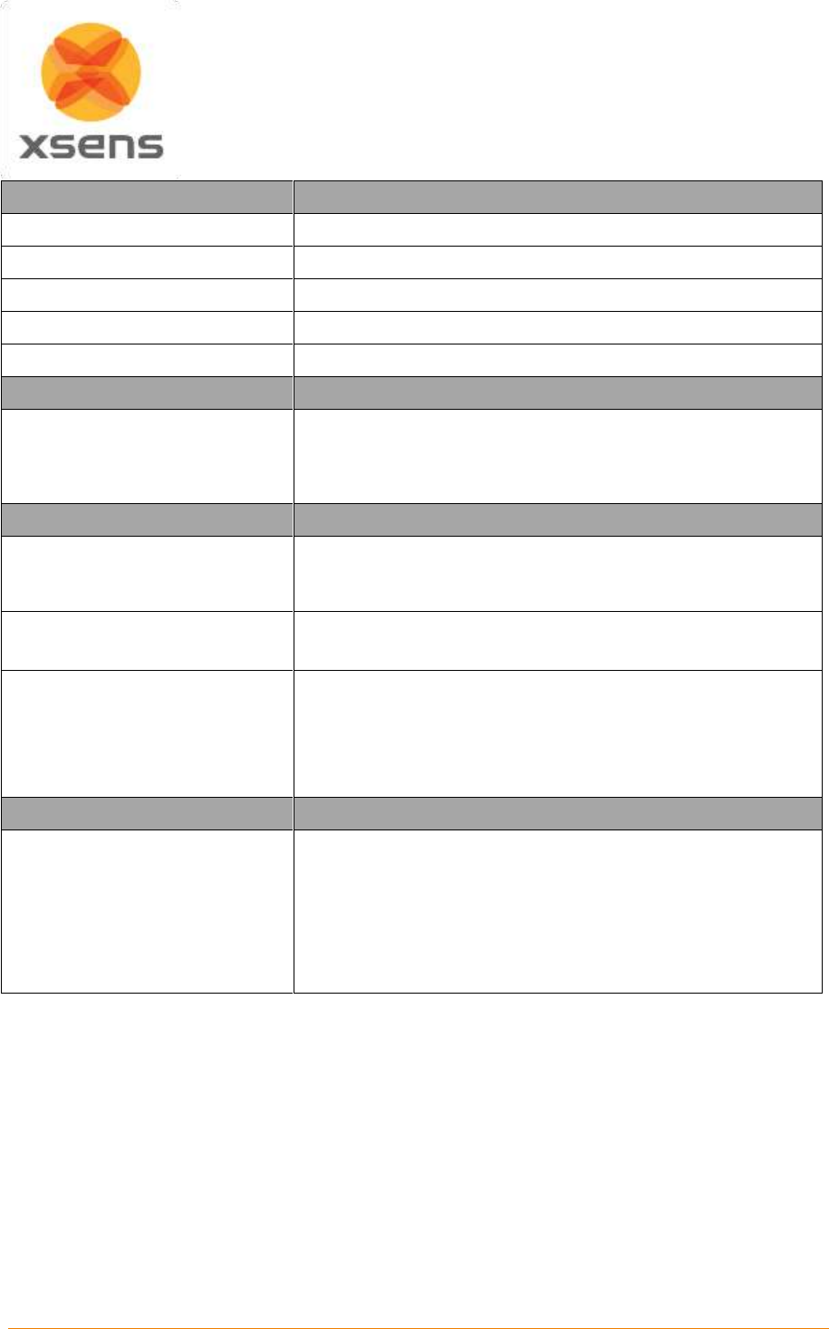
Document MV0319P.N
© Xsens Technologies B.V.
MVN User Manual
127
Tracker Performance
Static accuracy (Roll/Pitch)
0.2 deg
Static Accuracy (Heading)
0.5 deg
Dynamic Accuracy
1 deg RMS
Accelerometer range
MTx: ± 160 m/s2 (16 g) MTw: ±160m/s2 (16g)
Gyroscope range
± 2000 deg/s
MVN Performance
MVN human model
MVN uses a 23 segment biomechanical model with 22 joints.
Each joint is specified by statistical parameters for 6DOF joint
laxity. An advanced spine and shoulder model is used that
computes the kinematics of the spine and shoulder blades.
System Calibration
General
Flexible calibration scheme with instant feedback regarding the
expected accuracy. Calibration can be done without assistance
from a second person.
Minimum calibration time
10 seconds.
Basic calibration needs only subject length, foot length.
Advanced calibration
10 – 30 seconds per additional step.
Advanced subject specific calibration determines tracker
alignment and/or subject specific dimensions.
Calibration procedures for subjects with limited range of motion
are possible.
MVN Fusion Engine
Output
Full kinematics of each segment (position, velocity,
acceleration, orientation, angular velocity and angular
acceleration).
MVN Studio PRO additionally provides joint angle and CoM.
All at preset sample frequency (max 210Hz).
Double integration of body segment accelerations allows for
jumping/running (permanent floor contact is not needed).
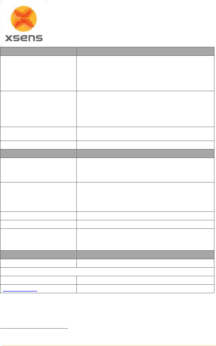
Document MV0319P.N
© Xsens Technologies B.V.
MVN User Manual
128
MVN Fusion Engine
3D translation capture
~1% error in traveled distance (without external aiding).
Advanced external contact model detects body-world contacts,
to enable crawling, sitting, cartwheel etc. Various friction
models (slippage etc.) are possible.9
Seamless fusion with aiding technologies possible, e.g. 3D
position from optical/GPS, or 2D image correspondences.9
Magnetic environment
Local, permanent disturbances
Full immunity to any magnetic distortions of knee and ankle
joint. Full immunity to temporary magnetic disturbances
(duration <30 seconds).
Visual warning of disturbed environment.
High degree of immunity, performance will depend on motion
and environment.
Soft tissue artifacts
Minimized to ~2 degrees RMS using redundancy in
measurement and biomechanical constraints.
Multiple person capture
Up to four person capturing on one pc
MVN Studio Software
Functionality
Easy and quick calibration
Real time preview of motion capture
Simultaneous recording and viewing of motion capture data
Replaying and editing of previously recorded motion data
Supported export formats
.BVH -Biovision Hierarchical Data
.C3D -Coordinate 3D data
.FBX – FiLMBOX
.MVNX – MVN Open XML format
Sample Frequency
60 – 240 Hz (default 240 Hz)
Wireless Update Rate
20-60Hz Depending on suit configuration
Data rate
37 MB/min @ 60 Hz
74 MB/min @ 120 Hz
158 MB/min @ 240 Hz
Legal Notice
Warranty
2 Years
MVN and Xsens are trademarks of Xsens Technologies B.V.
Patents Pending
www.xsens.com
9
Some features are only available in SDK, ask for possibilities.
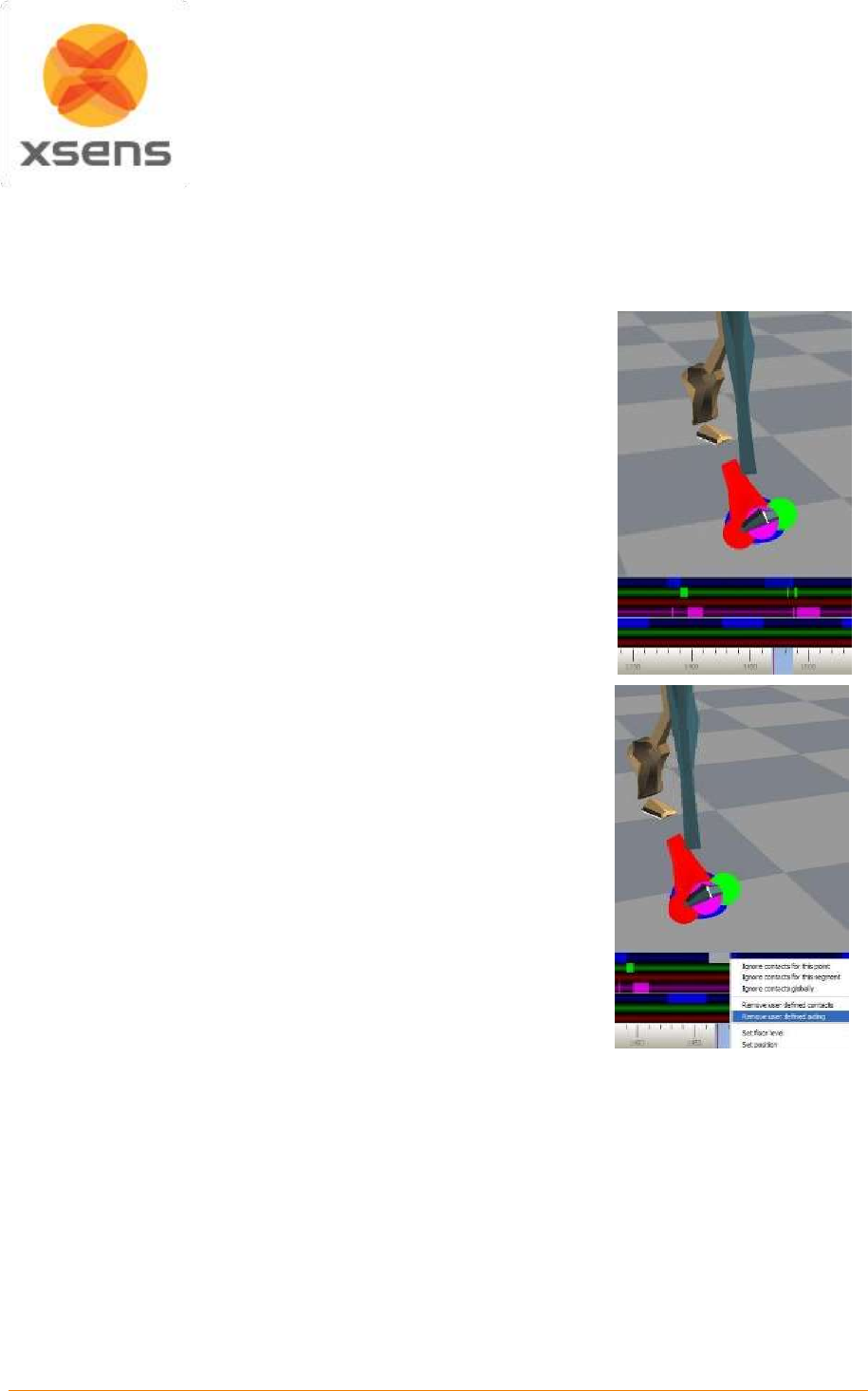
Document MV0319P.N
© Xsens Technologies B.V.
MVN User Manual
129
20 Contact point editing examples
The following section illustrates how to use the contact editing toolbar.
20.1.1 Example 1
In the originally recorded MVN file, a contact on the mid foot has been
wrongly detected. The result is an unlikely position of the foot segment
with respect to the lower leg and a discontinuity in the position of the total
character. Removing this contact will improve the data.
Click on the foot segment. Step forwards and backwards in time to
identify the wrongly detected or missing contacts.
Select the identified time frames by clicking the left mouse button.
The selected frames will be highlighted. By manually defining a
contact point, all other contact points of that frame will be removed
including contact points of segments other than selected.
To add contact points without removing existing points, hold the shift
button when the releasing the mouse button. This option should not
be used excessively, but maybe useful to optimize discrepancies
when two segments make contact at the same time frame.
If a wrong frame or contact point is selected, you can undo this by a
click on the right mouse button and select ‘Remove user-defined’.
To remove all contact points such that no segment has contact, click
and drag the right mouse button on the desired frames and select
‘Force no detection’. The contact bar will then show a black band.
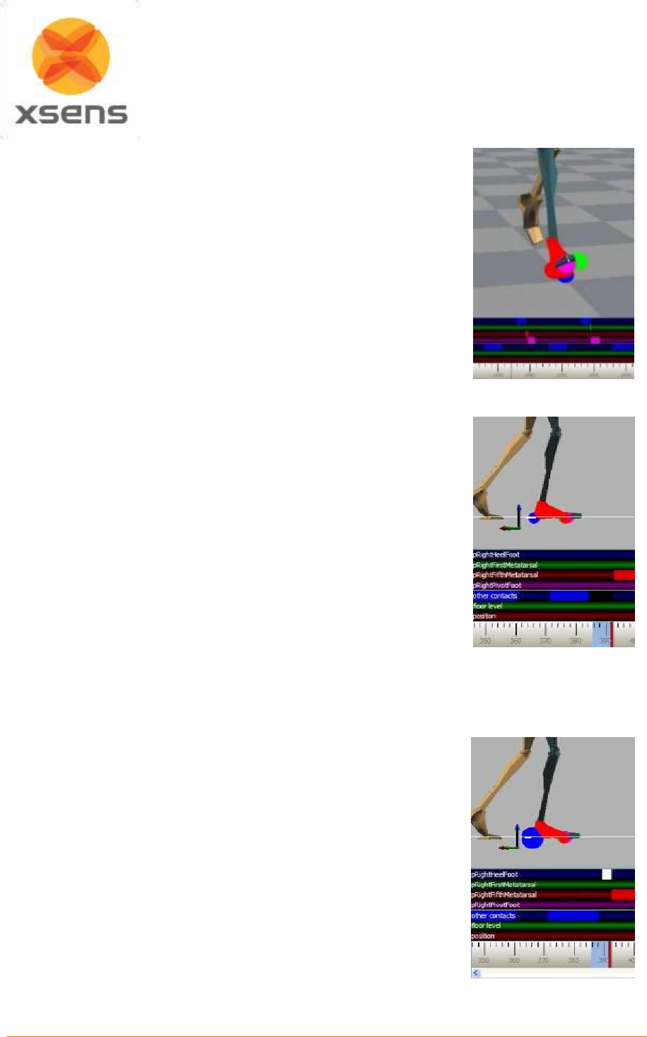
Document MV0319P.N
© Xsens Technologies B.V.
MVN User Manual
130
After editing the contact points, press the reprocess button or
‘Ctrl+Shift+P’. The MVN Fusion Engine will now re-compute all
kinematics using the original inertial sensor data taking the
overruled contact points into account.
20.1.2 Example 2
In the originally recorded MVN file, the foot is already on the
ground but the contact is detected too late. The result is that the
character seems to stick at a wrong contact and the foot slides
back.
Click on the foot segment. Step forwards and backwards in time
to identify the frames and possible contact points. In this case,
the heel (red sphere) is the most likely contact point to have
contact with the ground.
In the contact bar, select the frames of the heel (upper bar) with
the left mouse button. The selected frames will be highlighted.
After editing the contact points, press the reprocess button. The MVN
Fusion Engine will now re-compute all kinematics based on the
overruled contact points.
Verify the modified contacts. The red sphere should be enlarged
during the selected frames and foot slide should no longer occur
during these frames.
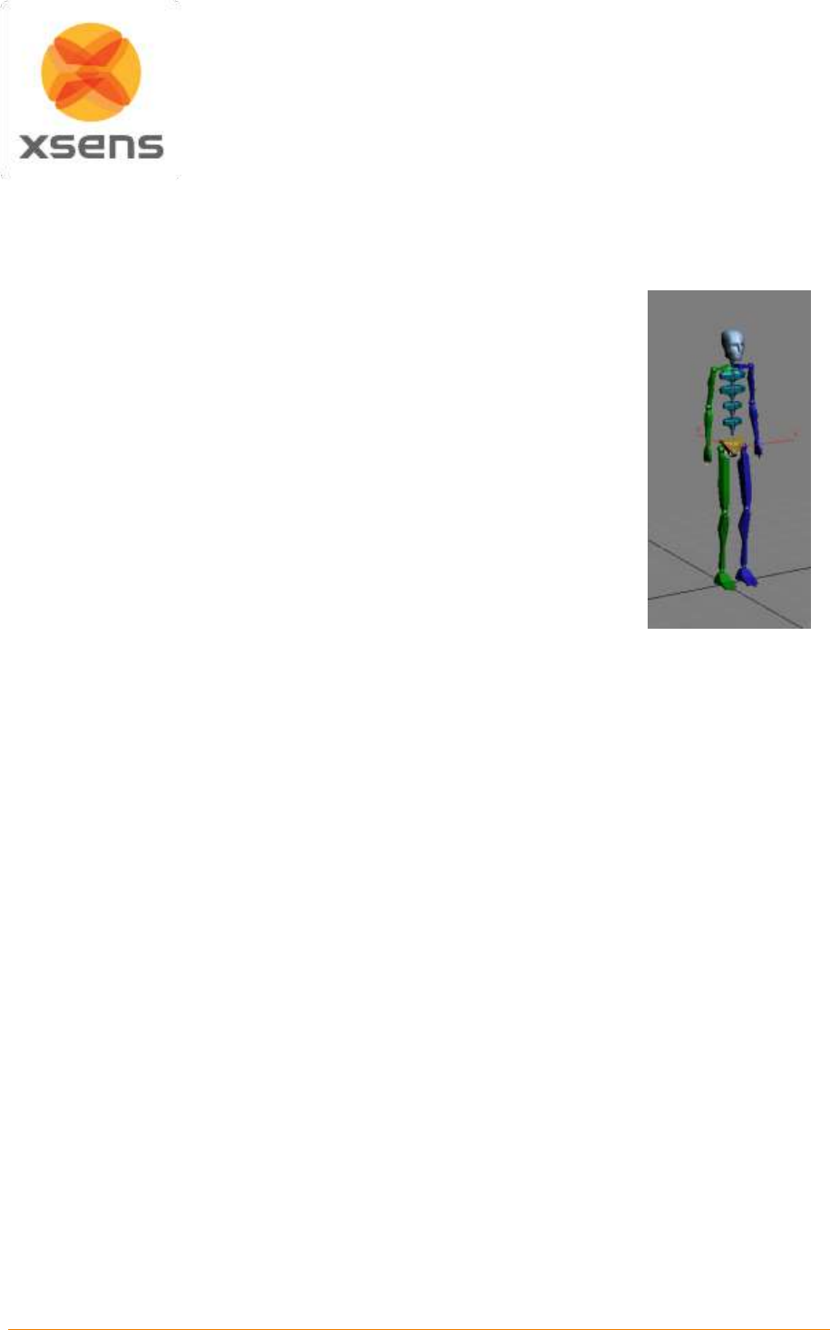
Document MV0319P.N
© Xsens Technologies B.V.
MVN User Manual
131
21 Working with different applications
21.1.1 Autodesk 3ds Max
In 3ds Max, a Biped system provides direct input of BVH files, including key-
frame reduction and footstep extraction. Choose the 3ds Max output format
when exporting to BVH. The exporter will apply a neutral pose hierarchy
instead of the T-pose hierarchy. The neutral pose for the Biped places the
figure upright along the +Z axis, facing forward along the -Y axis, left hand on
the +X axis. Hands are oriented with palms against the outside thighs, with
thumbs to the front side; fingers and thumb of each hand outstretched (open)
facing down along the -Z axis. Legs are together and straight at the knees.
When all joint rotation values are set to zero for the first frame of the BVH file,
the results displayed at frame zero in Biped should match the default position
of the Biped exactly.
A Biped has built-in anthropomorphic constraints which require that elbows and
knees are one degree-of-freedom hinge joints. The axis of rotation of the hinge
should ideally always be perpendicular to the arm's shoulder-elbow-wrist
triangle and the leg's hip-knee-ankle triangle. If the hinge joint constraint is
violated, biped’s converter must decide whether to satisfy the orientation data
or satisfy the elbow/knee positioning based solely on the point locations.
In the Conversion Parameters Dialogue Box, if the ‘Angle’ radio button is selected (recommended), the
limb's triangle attempts to match the hinge to the Euler matrix axes. This may deviate from the position
posture. If the ‘Point’ radio button is selected, the limb's triangle matches the positions of the actual
points. This may deviate from the specified Euler angles. However, in both cases, the limb always moves
to hit the IK position of the wrist or ankle, so if Euler angles are given that are not aligned with the natural
hinge joint, the axis is projected to the nearest axis that satisfies the wrist/ankle IK constraint (that is,
one axis must be normal to the line joining the arm's shoulder-wrist or the leg's hip-ankle).
21.1.2 Autodesk MotionBuilder
Autodesk MotionBuilder is a powerful animation package which features many tools for forward and
inverse kinematic manipulation and retargeting. Use the following steps to drive your model in
MotionBuilder.
1. Import the BVH motion file into the MotionBuilder.
2. On the first frame of the motion set the BVH skeleton reference into the T-Pose.
3. Characterize the BVH skeleton with the MVN character template.
The MVN character template ‘MVN BVH Character.fbx’ can be found in the folder:
%AppData%\Xsens\External\MotionBuilder\Templates\MVN.
4. Import the character model you want to animate.
5. In the control rig of the imported model choose as input ‘Character Input’ (MVN BVH).
6. Play the animation and plot to character.
Poser 6
Choose the Poser BVH exporter format when exporting to BVH. The exporter will rename certain labels
and combine the chest channels since Poser can only handle 1 abdomen and 1 chest channel. Load
the model you want to animate into Poser. Import BVH data and choose the options arms aligned with
X-axis, and Scale Automatically.
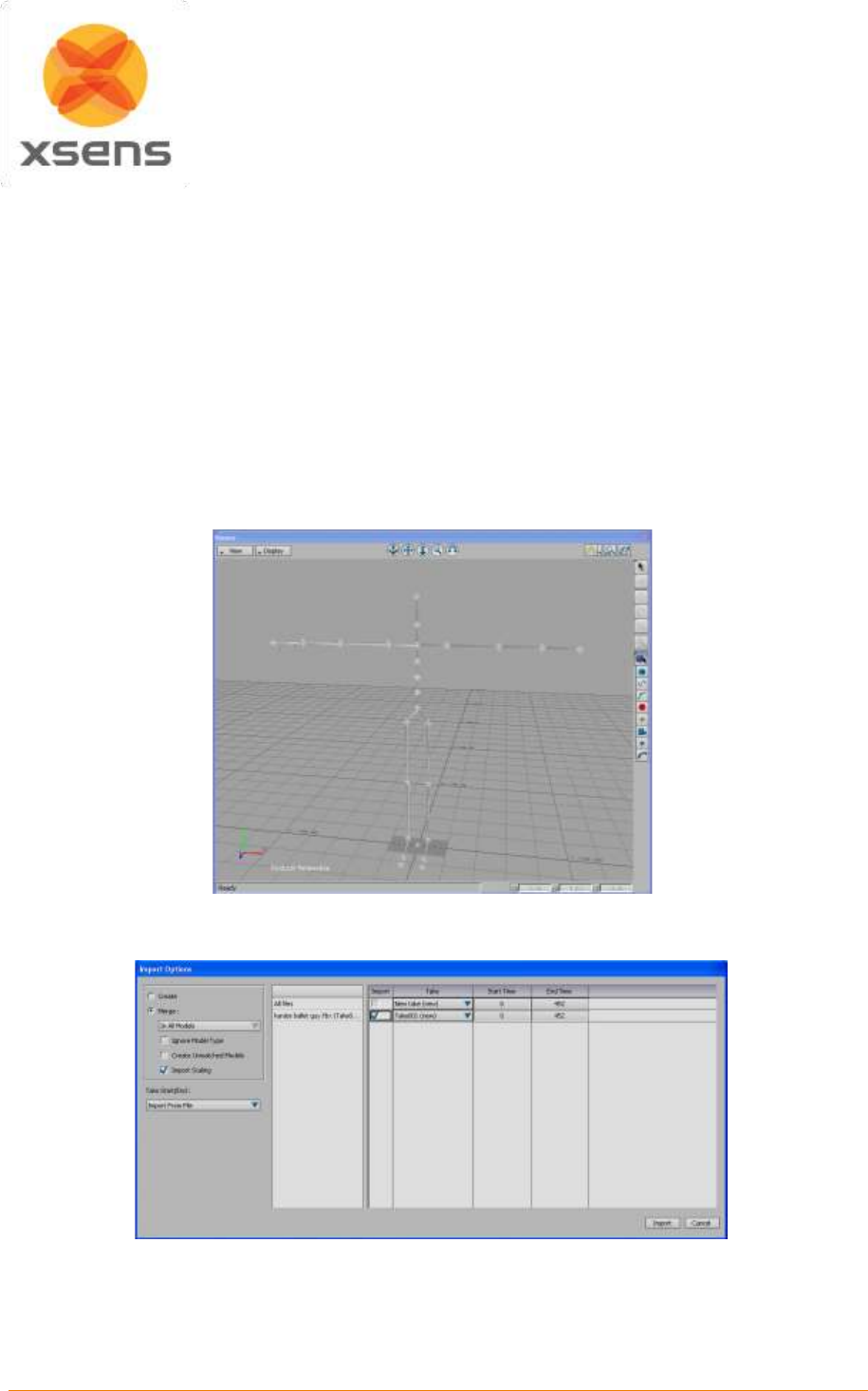
Document MV0319P.N
© Xsens Technologies B.V.
MVN User Manual
132
Poser 7 note:
There is a known issue in Poser 7 regarding figure orientation. It will introduce an odd twist in the
orientation of the segments. Please contact Poser support for information about an update.
21.2 MotionBuilder workflow
To import FBX in MotionBuilder, the MVN script called MKMVN01.py (which can be found in
%AppData%\Xsens\External\MotionBuilder\Templates\MVN) should be copied to one of the following
folders:
Windows 7 64-bit, MotionBuilder 64-bit installed:
C:\Program Files\Autodesk\MotionBuilder 2014\bin\config\Scripts
C:\Program Files\Autodesk\MotionBuilder 2015\bin\config\Scripts
1. Load the template file ‘MVN FBX import.fbx’. In the Viewer window, nulls represent the joint positions
and rotations of the skeleton.
2. Import the motion data >‘Import & Merge’. Select the ‘Import Scaling’ option.
3. Plot the animation to the control rig – this can be done by pressing function key ‘F10’ which runs the
MVN script. A filter is applied to eliminate gimbal lock.
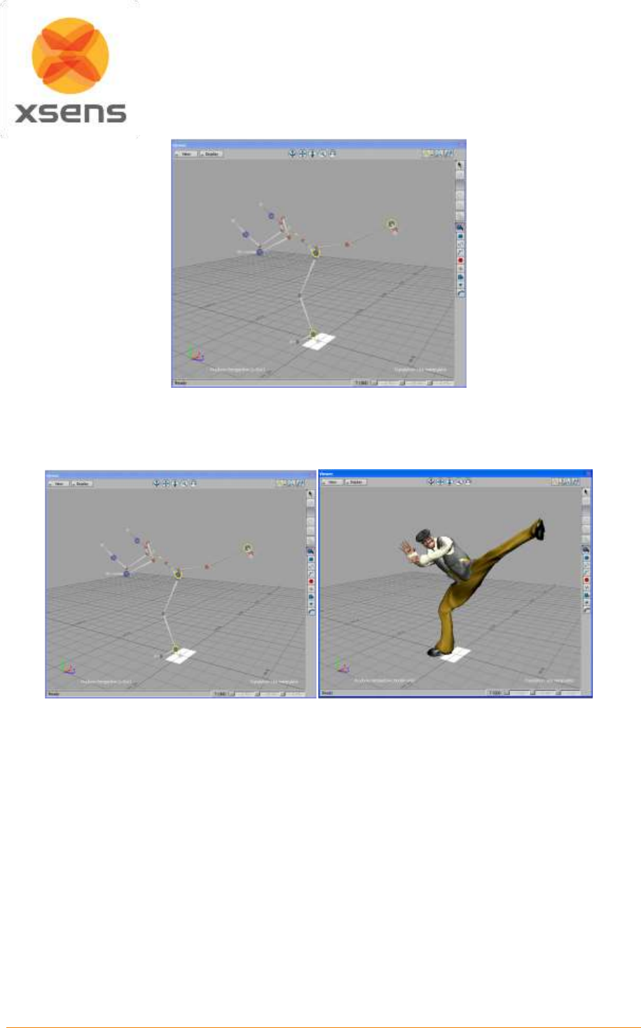
Document MV0319P.N
© Xsens Technologies B.V.
MVN User Manual
133
4. The skeleton is a character in MotionBuilder and the control rig contains the captured motion. You
can now simply merge another character in the scene and transfer the animation by using the
character input option of MotionBuilder. You can also save the animation in the character controls.
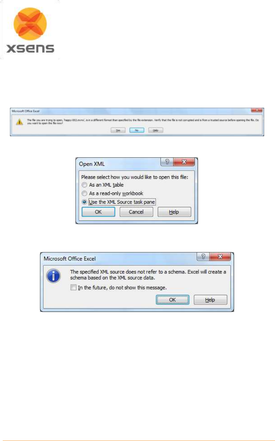
Document MV0319P.N
© Xsens Technologies B.V.
MVN User Manual
134
22 Importing MVNX files to other programs
22.1.1 Import to Microsoft Excel
File and open the MVNX file.
It is likely that the following warning is generated. Click YES.
Next the following menu will pop up:
As in this example, select the XML source pane option.
Another warning message appears:
Click OK.
The window will now look like:
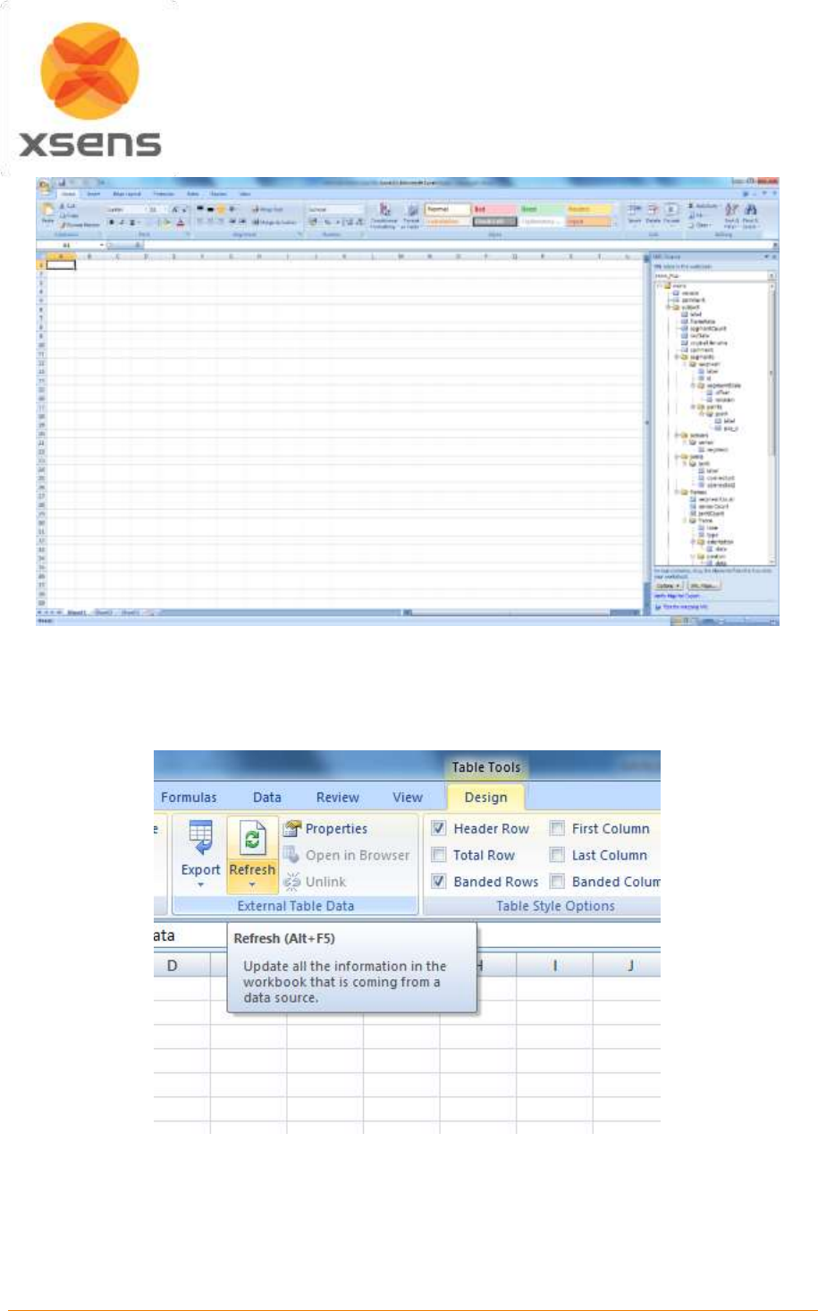
Document MV0319P.N
© Xsens Technologies B.V.
MVN User Manual
135
The information of use is in the panel on the right hand side. This data contains all of the data that was
exported. To view data, select the data of choice e.g., joint angles from the list of parameters (sensors,
segments, points, frames). Go to frames, joints angle and drag that label to e.g. Cell A1. A title box will
appear. To view data, click refresh:
It is clear that data is present, but it is still not defined.
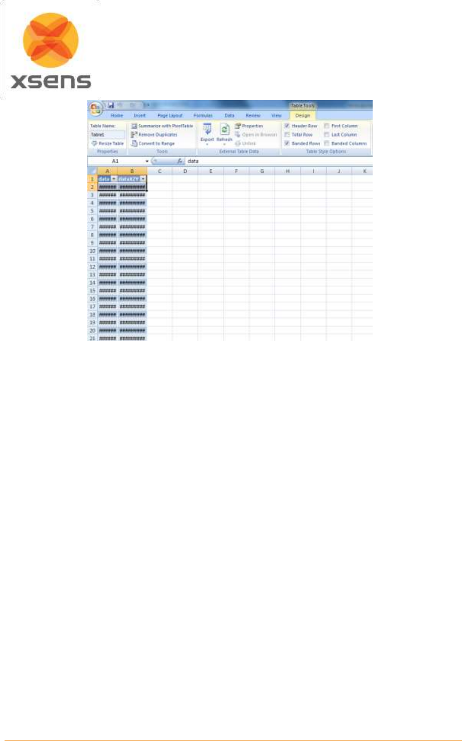
Document MV0319P.N
© Xsens Technologies B.V.
MVN User Manual
136
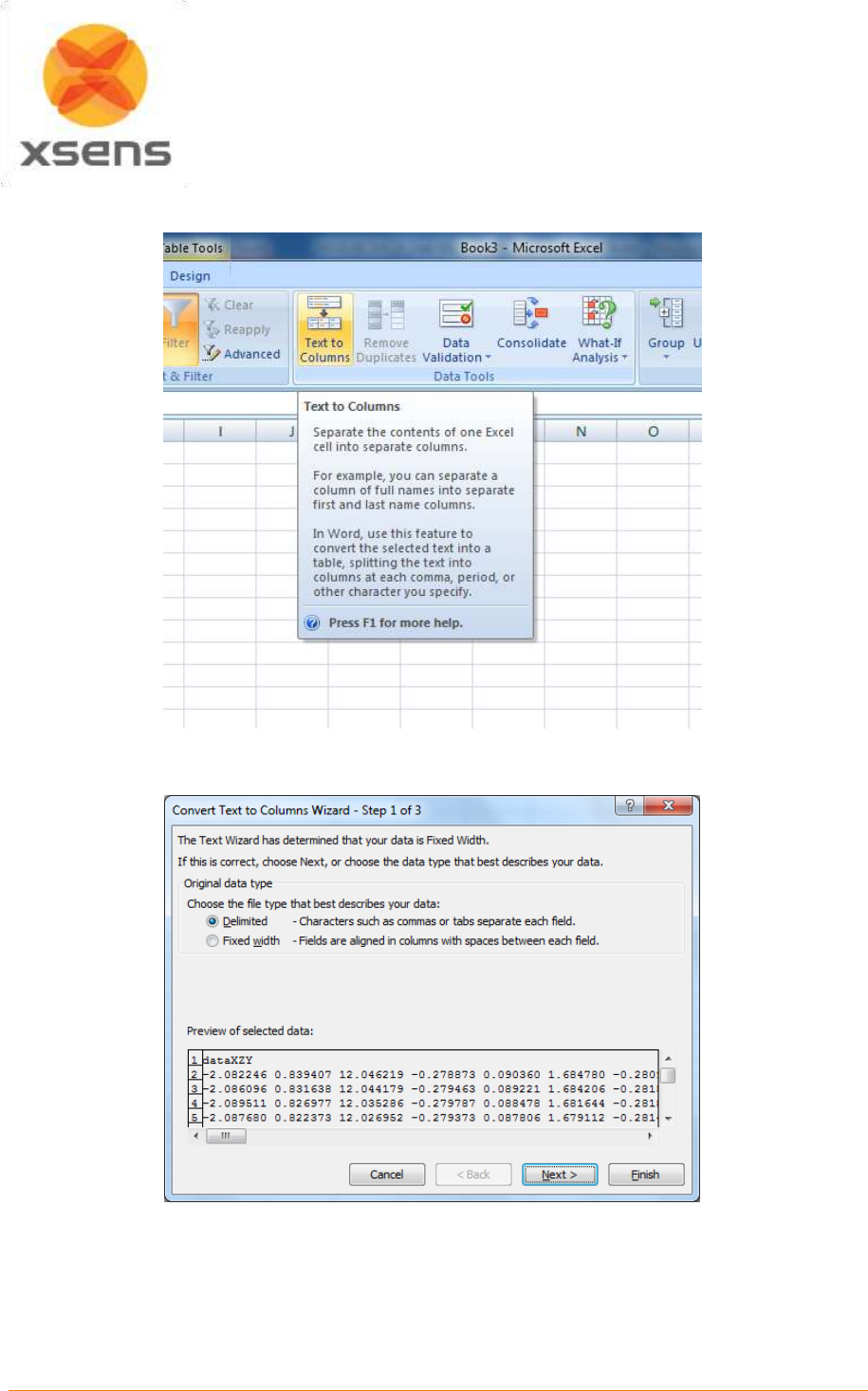
Document MV0319P.N
© Xsens Technologies B.V.
MVN User Manual
137
To work with the data, go to the data menu (Data Tab in Excel 2007). Select “Text to Columns”.
The data is delimited.
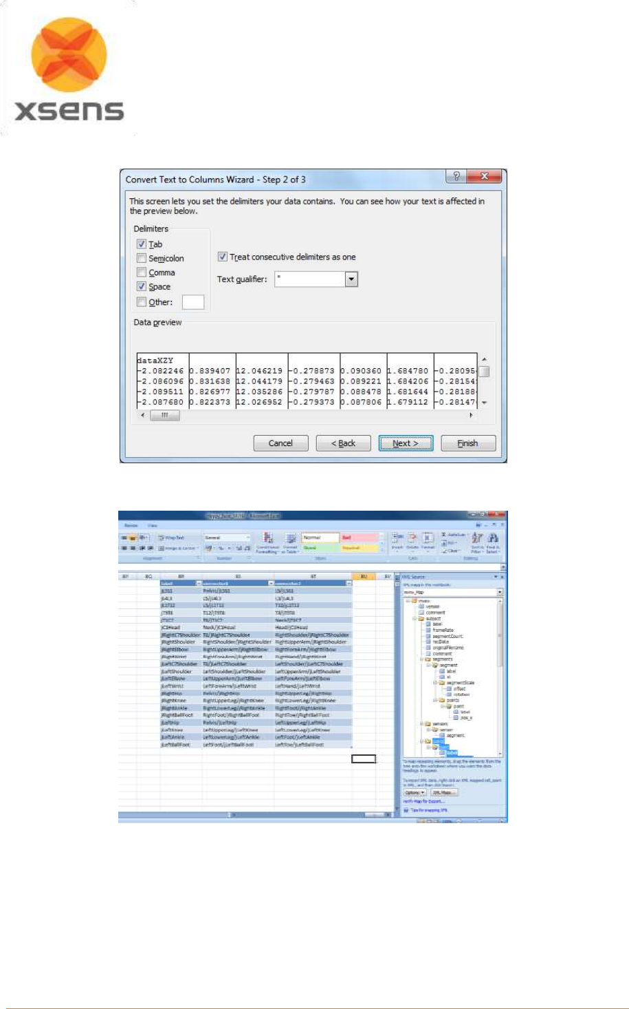

Document MV0319P.N
© Xsens Technologies B.V.
MVN User Manual
139
22.1.2 Import to MATLAB
Import MVNX files using the MATLAB files in the MATLAB Installer of MVN Studio. Below is a copy of
the information stored in “main_mvnx.m”. This file intended simply as an example. The user is expected
to expand upon this for their own use, depending on data they have exported to mvnx.
The example code contains:
main_mvnx.m and load_mvnx.m. The file main_mvnx is detailed below. It calls the function
load_mvnx.m, which is based on the MATLAB function for reading XML files.
Example code to read the file:
main_mvnx.m
tree = load_mvnx(filename);
% read some basic data from the file
mvnxVersion = tree;
fileComments = tree.subject.comment;
%read some basic properties of the subject;
frameRate = tree.subject.frameRate;
suitLabel = tree.subject.label;
originalFilename = tree.subject.originalFilename;
recDate = tree.subject.recDate;
segmentCount = tree.subject.segmentCount;
%retrieve sensor labels
%creates a struct with sensor data
sensorData = tree.subject.sensors.sensor;
%retrieve segment labels
%creates a struct with segment definitions
segmentData = tree.subject.segments.segment;
%retrieve the data frames from the subject
nSamples = length(tree.subject.frames.frame);
%pre allocate
%pre allocate some memory for the position of Segment1
p_Segment1 = zeros(nSamples,3);
%read the data from the structure e.g. segment 1
for i=[1:nSamples]
p_Segment1(i,:)=tree.subject.frames.frame(i).position(1:3);
end
%Plot
plot(p_Segment1)
figure
plot3(p_Segment1(:,1),p_Segment1(:,2),p_Segment1(:,3));

Document MV0319P.N
© Xsens Technologies B.V.
MVN User Manual
140
23 Synchronization with Third Party Devices
23.1 The Hardware
MVN BIOMECH Awinda uses the Awinda Station for synchronization.
From MVN Studio 4.1 and onwards, a Sync Station is provided with MVN BIOMECH for synchronization
purposes. Details on initializing the synchronization of MVN are provided in Section 7.2.14. The purpose
of this section is to provide some in-depth information about the synchronization possibilities.
The Awinda Station was originally created as a wireless master to control the Xsens MTw kit. The
Awinda Station and Sync Station were created specifically for the biomechanics market, where
synchronization with third party devices is an essential aspect of biomechanics research. For this reason
these Stations are equipped with 4 BNC connectors, two for receiving TTL pulses (Sync IN) and two for
sending TTL pulses (Sync OUT).
The hardware clock of the Awinda Station is very accurate. As an indication of the clock accuracy, the
error in the Awinda Station’s clock has a maximum of 1 µs every second (1 ppm). Therefore, in general,
the recommended scenario is that users relying on very tightly coupled synchronization use MVN
BIOMECH Awinda, and use it with the Sync Out settings.
With MVN BIOMECH Link, there is additional hardware making synchronization possible, this is software
synchronization. It is essential that the user understands that software controlled synchronization can
lead to undefinable latencies between button click in the software and reception of this signal.
Note that to synchronize with third party devices, BNC connectors are required at the Awinda Station or
Sync Station side. Since there are a multitude of system-specific connectors for third party systems,
Xsens does not provide the cables or connectors. Please contact the respective third party providers or
user manuals for details their hardware requirements.
23.1.1 Important note when receiving 5V synchronization pulses
On the back of the Awinda and Sync Stations are four BNC ports, two Sync In ports and two Sync Out.
The ports have been configured to send (Sync Out) or receive (Sync In) TTL pulses 0-3.3V.
This 3.3V is s lower than the voltage sent by some devices, which will be synchronized with the MVN
System. These other devices are based on 5V TTL levels. For this reason it is advised to separately
purchase (from eg Farnell) a 3.3 - 5V / 5V - 3.3V SMD level translator. This will prevent damage to the
SyncIn ports of the Awinda or Sync Station when receiving 5V pulses from third party systems. In general
sending a 3.3V pulse from an Awinda or Sync Station SyncOut port is fine. Therefore unless a threshold
of 5V of the third party system is required, in which case the 3.3V-5V SMD level translator will be
required.
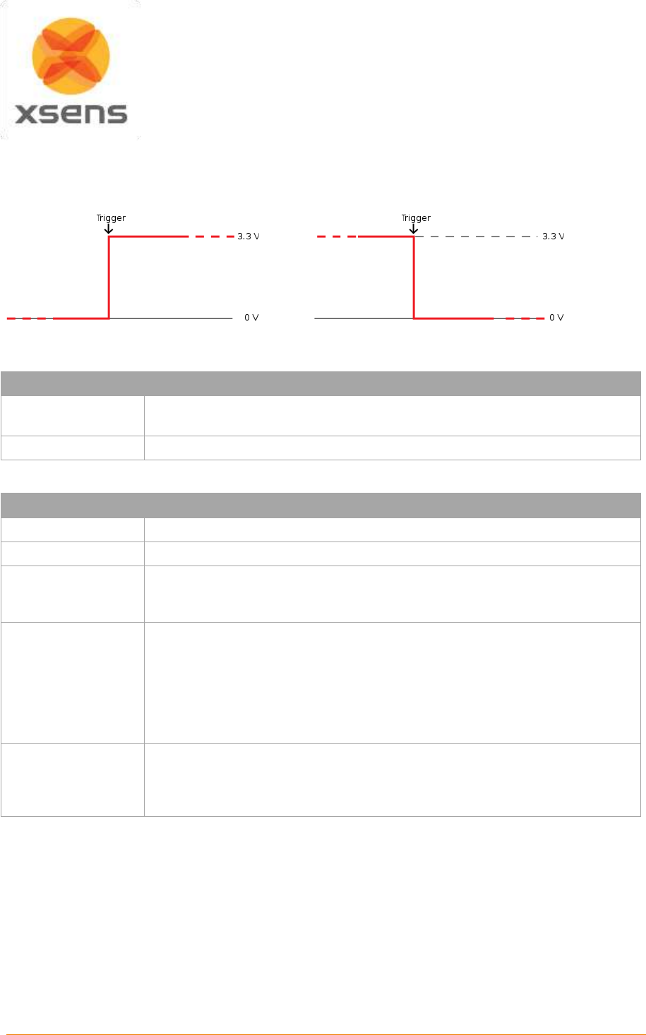
Document MV0319P.N
© Xsens Technologies B.V.
MVN User Manual
141
23.2 Sync In
Sync In means that a third party device sends a control signal to the Awinda Station. The Awinda Station
can detect polarity changes on the input lines. This trigger may be a rising or falling edge as illustrated
in the following figures:
When a trigger is detected on one of the input lines, the Awinda Station can be configured to perform a
certain action. Combinations of any of the following are possible on each Sync In port:
Sync Type
Description
Start Recording
External system sends a start recording trigger. On the Awinda Station, this
will be the next frame.
Stop Recording
External system sends a stop recording trigger.
A number of parameters can be set for each action:
Parameter
Description
Sync Line
The sync line to activate.
Pulse Polarity
Rising or falling edge, or rising and falling.
Trigger Once
It is not recommended to select Trigger once if more than one recording
using synchronization of multiple systems will be made. This is a failsafe
option in the case third party systems send pulses throughout recordings.
Skip First
The number of initial occurrences of the sync trigger to skip. This is useful if
a well-defined delay is expected, or if the external signal sends the same
signal to generate both a start and stop recording. Take for example the
command to start recording and stop recording, one signal sent to the
Awinda Station can generate two different commands. Therefore if both start
and stop are on the same sync line, skip first should be 1 for stop recording,
ensuring that the second trigger, not the first, causes recording to stop.
Skip Factor
The number of occurrences of the sync trigger to skip in between trigger
signals. In the same way that was described in Skip First (above), skip
factor, for start and stop recording on one sync line should be set to 1, to
ensure that the first trigger starts the recording and the second stops etc.
NOTE: If the user selects Sync In but selects a function from the drop-down menu that is only available
as Sync out (namely, settings other than start or stop recording), the software will automatically change
the sync channel to Out 1.
Therefore care is required when matching sync in or out with the functions available.
Document MV0319P.N
© Xsens Technologies B.V.
MVN User Manual
142
23.3 Sync Out
Sync Out is the command that enables the Xsens system to send a trigger pulse for synchronization
purposes. A control signal is sent via the Awinda/Sync Station, from MVN Studio to the third party
hardware.
Sync Type
Description
Start Recording
Upon clicking the record button in MVN Studio, the Awinda Station starts the
recording and consequently sends a start recording trigger to the third party
system.
Stop Recording
Upon clicking the record button in MVN Studio, the Awinda Station stops
recording and sends a stop recording trigger to the third party system.
Go to Operational
The default polarity of the output line is always low. However, for input
triggers that assume high polarity, the polarity of the line must be set high
beforehand. This becomes possible, using 'Go to operational'. When ‘Go to
Operational’ is selected on the same line as the assumed high polarity, the
polarity is changed to high, preparing the system for sync.
Interval Transition
Measurement
A frame / or interval transition at the Station can be used to give a signal to
the external system, indicating the end of the strap-down integration interval
over which data is calculated. Selecting this option, the frame transition is
sent from the moment that “Start Measuring” is selected.
Interval Transition
Recording
See Frame transition Measurement
Selecting this option, the frame transition is sent from the moment that a
recording is started. This is a very useful option to implement, to ensure that
during a recording, the clocks of the synchronized systems are known,
ensuring that any drift can be compensated for.
A number of parameters can be set for each action:
Parameter
Description
Sync Line
The sync line to activate.
Pulse Polarity
Positive pulse (where the polarity is initially low [0V] and goes high [3.3V]).
Negative pulse (where polarity is initially high [3.3V] and goes low [0V]).
Trigger Once
It is not advised to select Trigger once, if more than one recording using
synchronization of multiple systems will be made.
Skip First
Number of initial sync pulses to skip. This command is useful if a well-defined
delay is expected between the Xsens and the third party system. It may also
be needed if the third party, like the Xsens system uses the same pulse
properties to trigger different actions. See description provided above for
Sync In.
Skip Factor
Number of sync pulses, between the sync pulses delivered, to skip. See
Sync In Table description.
Pulse Width
Some systems wait for a signal of a minimum pulse width before generating
the desired synchronization action. The Awinda / Sync Station can send a
pulse with a duration of up to 99ms to a third party system. It is not
recommended to send a signal longer than a frame width.
Specify 0 ms to generate an infinite pulse width.
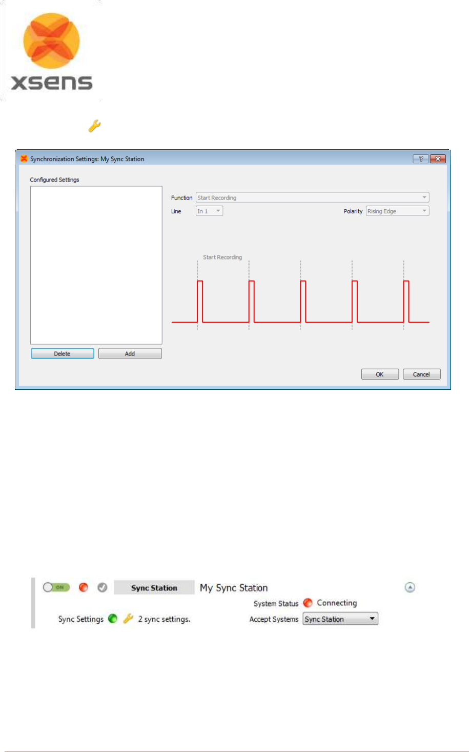
Document MV0319P.N
© Xsens Technologies B.V.
MVN User Manual
143
23.3.1 Settings in MVN Studio
Once the spanner has been clicked, a new menu appears:
Figure 70: Sync settings window in MVN Studio
To add a synchronization type, click “Add”, all settings become available, to be set manually or using
the drop down menus.
Note that the Awinda/Sync Station can accept both rising and falling edges. The Pulse Polarity should
be chosen depending on the requirements of the third party device. Also, check with third party systems
what the threshold of the Pulse Width must be before entering a pulse width. Some example settings
are provided in Section 23.7.
When all desired parameters have been set, click “OK”. This closes the sync settings window. Now in
the Session Configuration interface, the number of settings is displayed, indicating to the user that sync
is set and if the system is enabled, sync will be enforced. Below shows the result when start and stop
recording on line Sync In 1 have been set.
This is an important point to note: The Configured Sync Settings are saved in the configured system.
Therefore when a given configuration is enabled the sync settings of this enabled configuration are used.
23.4 Important Notices for Sync In
When the Awinda Station is configured to start recording upon receipt of a trigger, it initializes recording
at the start of the following frame. The Awinda Station cannot trigger a start recording command between
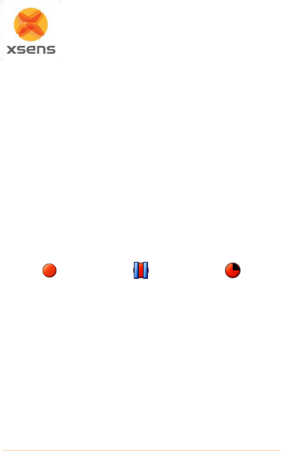
Document MV0319P.N
© Xsens Technologies B.V.
MVN User Manual
144
frames since data received in a given frame is measured in the previous one. Therefore, delaying the
recording in this way ensures that data is not recorded prior to the external trigger indication.
In the same way, recording should not be stopped between frames, since data received in a given frame
was measured during the previous frame. Therefore, the Awinda Station stops recording immediately
after the current frame.
23.4.1 Sync In Recommended Settings
Note that the preferences menu includes “Skip first” and “Skip Factor”. The definitions of these have
been provided above; however for practical use consider the following:
When the Awinda Station is triggered to start and stop a recording, on one line, it will blindly receive
3.3 V pulses on that line. Since all pulses are the same, the Station requires further instructions about
what to do with each pulse. In the software, a translation has been put in place to carry out a certain
action with each pulse.
Therefore, to start a recording, one must give an initial pulse. The second pulse, should indicate a stop
recording, therefore the skip factor in “Start Recording” should be set to 1. In Stop Recording, the first
pulse should not trigger a stop (it was just used to Start Recording); so a Skip First of 1 must be input,
and to ensure that every other pulse thereafter stops the recording, a Skip Factor of 1 must be input.
This means that Start Recording is commanded on pulse 1, 3, 5 etc and stop recording on 2, 4, 6 etc.
23.5 Sync In with MVN Studio
When Sync In is in use, after configuration, and when ready to record, users should click Record, to
prepare the system for the external trigger. The record icon changes from the normal red dot to one with
the pause symbol overlaid. When recording has been triggered by the external system, the record button
will indicate as such (most right icon shown below):
Record button prior to
depression
Record button when depressed
and waiting for Sync In signal
Record button during recording
(and temporarily during
flushing)
23.6 Sync Out with MVN Studio
When the parameters have been set for MVN Studio to control the start and stop of recordings, each
time the record button in MVN Studio is depressed, a TTL pulse will be sent to the specified Sync Line.
The receiving system must be configured to take the specified action.
Of course, ensure that the BNC connector is connected to the correct Sync Out line(s).
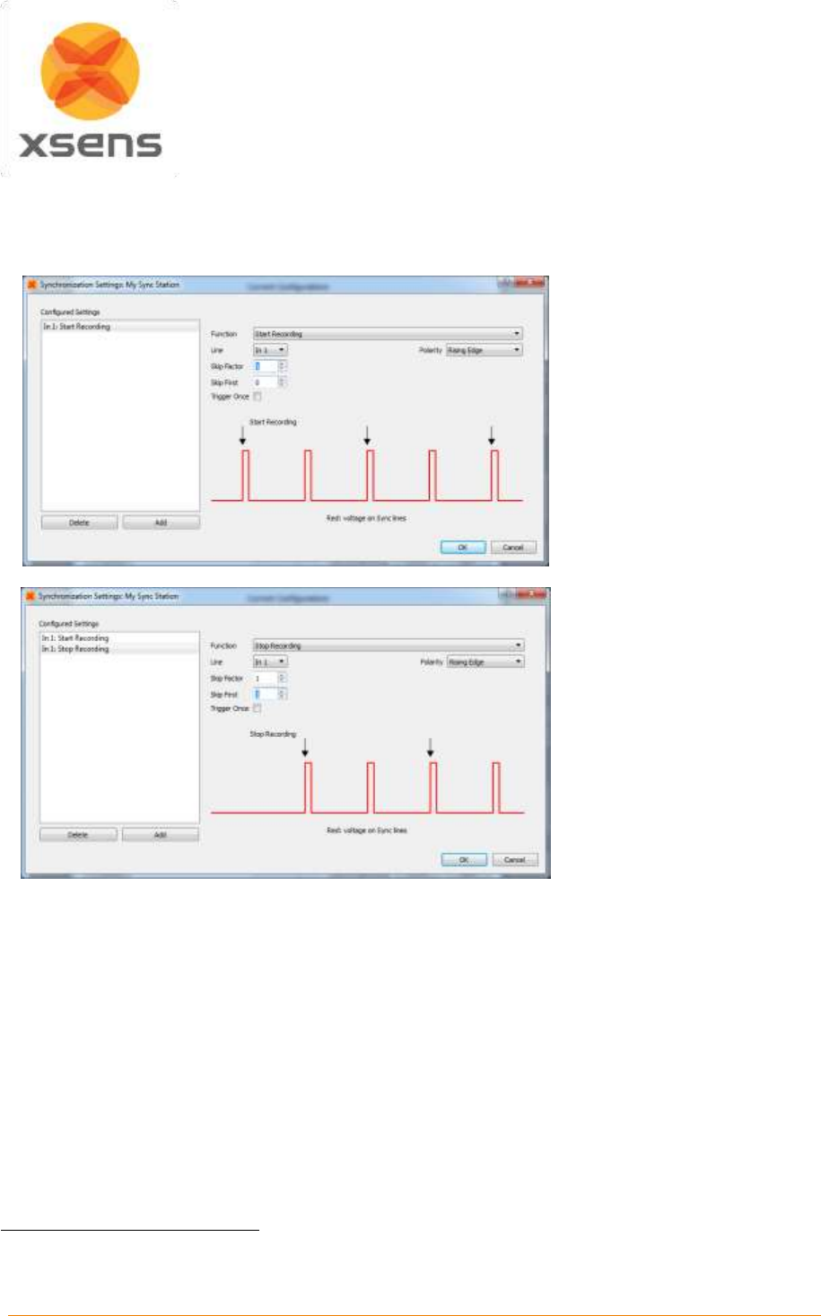
Document MV0319P.N
© Xsens Technologies B.V.
MVN User Manual
145
23.7 Synchronization Examples
23.7.1 Start and stop recording of third party devices using single pulse
Third party device starting and stopping recording of Xsens system, on Line 1 of the Sync In port.
Click “Add”
Select Sync Type Start
Recording
Select Sync Line: In 1
Pulse Polarity: Rising Edge10
Skip First = 0
Skip Factor = 1 (so that
every other pulse will start a
recording in MVN Studio)
Trigger Once: Unchecked11
Click “Add”
Select Sync Type Stop
Recording
Select Sync Line: In 1
Pulse Polarity: Rising Edge
Skip First = 1 (first trigger
starts recording, so it should
not also send a signal to stop
- or this causes confusion for
Awinda Station)
Skip Factor = 1 (so that
every other pulse will stop a
recording in MVN Studio)
Trigger Once: Unchecked
The above example indicates how to allow a signal of 3.3V enter the Sync In 1 port, of the Awinda
Station. The first upward going pulse (and subsequent odd numbered pulses), received on the Awinda
Station, will start recording (Polarity = rising edge). The second upward going pulse (and subsequent
even numbered pulses), received on the Awinda Station, will stop recording.
23.7.2 Start and Stop Recording Third Party Devices with Infinite Pulse Width
It is of course also possible, to configure that for example the upward rising edge causes the start of
recording and the negative direction edge causes stop recording, this may be useful in the event that a
third party devices needs to be active high to record data.
To do this, the following settings should be input:
10
Note that this setting depends on the signal from third party system.
11
To ensure that a series of recordings can be made.
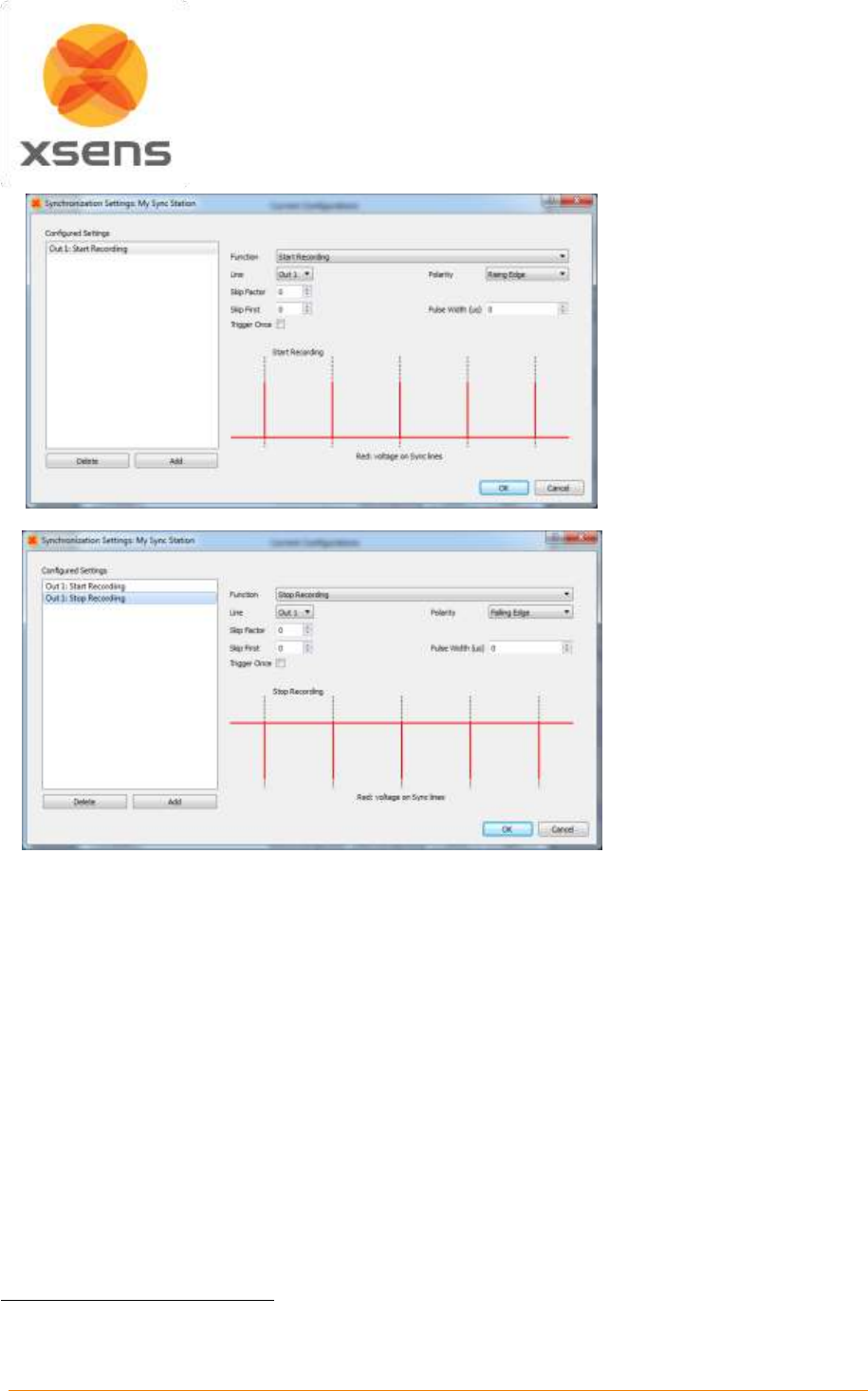
Document MV0319P.N
© Xsens Technologies B.V.
MVN User Manual
146
Click “Add”
Sync Type: Start
Recording
Sync Line: Out 1
Pulse Polarity: Rising Edge
Pulse Width = 0µs12
Skip first = 0
Skip factor = 0
Trigger Once: Uncheck
Click “Add”
Sync Type: Stop Recording
Sync Line: Out 1
Pulse Polarity: Falling
Edge
Pulse Width = 0µs[12]
Skip first = 0
Skip factor = 0
Trigger Once: Uncheck
Note:
Stop recording time may not be on the last sample recorded.
In any synchronization situation, there should only be one master. It is necessary to elect a master,
either an Awinda Station, or a third party device.
23.7.3 Synchronizing with Noraxon EMG
Synchronization was successfully tested between MT Manager, for the MTw Development Kit and
Noraxon TeleMyo system. While we assume that the results will be just as successful with MVN, this
has not yet been tested.
The steps described below describe how to make it possible for the Awinda Station to send a
synchronization signal (Xsens is Sync Out and Noraxon is Sync In) and how to receive the
synchronization signal (Noraxon is Sync Out, Xsens Sync In).
Of course, care must be taken when placing the EMG electrodes with the straps or suit of MVN.
12
Note that MVN Studio 4.1 use the unit microseconds for pulsewidth. For current users, all previous millisecond
units used should be multiplied by 1000.
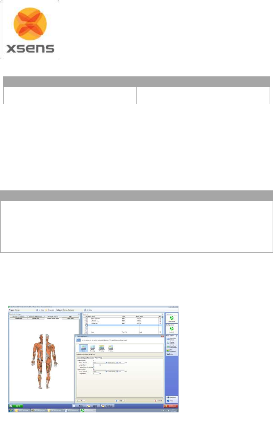
Document MV0319P.N
© Xsens Technologies B.V.
MVN User Manual
147
23.7.3.1 Awinda Station Sends Sync Signal (Noraxon Receives Sync Signal)
Hardware requirements:
Noraxon Hardware
Xsens Hardware
Wireless EMG transmitters
1 TeleMyo DTS (plus antenna)
MVN System
Awinda Station
Both systems of course also need related cables to connect to each other (with BNC connectors at each
end) and a USB cable to connect to the PC.
In addition to the normal MTw hardware setup, also connect the BNC connector from the TeleMyo DTS
to Sync Out 1 on the Awinda Station. Connect the USB connection between the TeleMyo DTS and the
PC. When switched on, the DTS will display “USB ready”.
23.7.3.2 Software Setup in MVN Studio
There is no fixed order for configuring MVN Studio in terms of Synchronization configuration. This can
be done before or after a new recording session.
Synchronization on Sync Out Line 1:
Sync Out
Select Start Recording
Select Out 1
Polarity: Rising Edge
Pulse width = 10 ms
Trigger Once: Uncheck
Skip first = 0
Skip factor = 0
Select Stop Recording
Select Out 1
Polarity: Rising Edge
Pulse width = 10 ms
Trigger Once: Uncheck
Skip First = 0
Skip Factor = 0
23.7.3.3 Software Setup Noraxon MyoResearch Software:
The example given below is for is gait analysis, measuring the medial gastrocnemius, tibialis anterior,
semitendinosus and the rectus femoris. For an 8-Channel EMG system, Channel 9 is selected as the
synchronization line in the Noraxon MyoResearch Software. If a 16 channel system is in use, this is the
17th channel.
Return to the main menu,
under >Measuring Options, go
to >Recording Options, then
>Triggering tab.
Check the check box beside “Start Recording”;
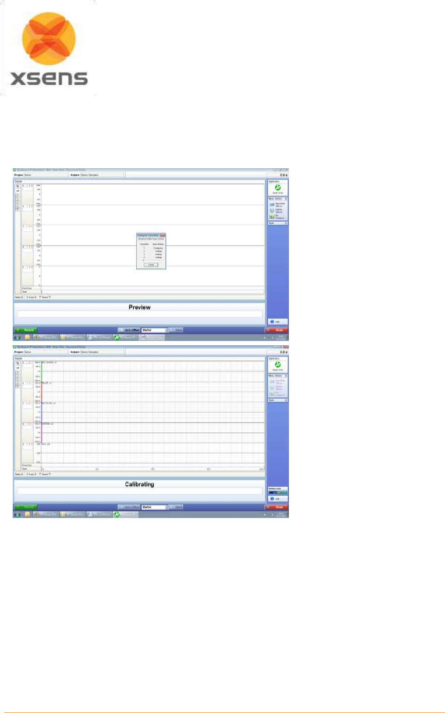
Document MV0319P.N
© Xsens Technologies B.V.
MVN User Manual
148
Go to the drop down menu beside “When Channel”, select “Sync”;
Select Rises Above (ensure that this is also the direction indicated on the mini-receiver);
Input e.g. 0.5V
Longer than 5ms
Repeat settings for Stop Recording.
Navigate further through the software.
The Noraxon software
initializes the EMG signals.
When this screen is reached,
click record, on the bottom left
hand side of the screen on the
Noraxon software.
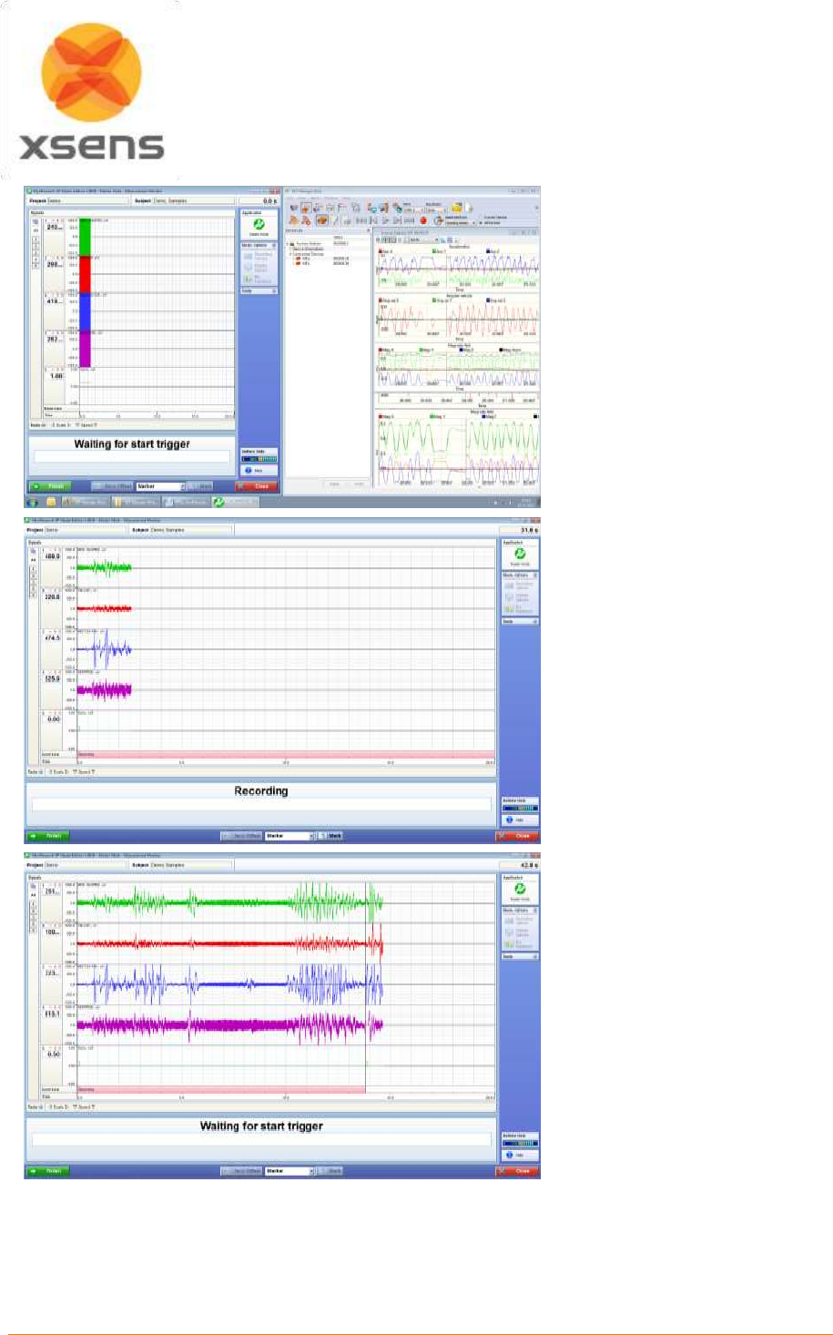
Document MV0319P.N
© Xsens Technologies B.V.
MVN User Manual
149
The software indicates that it
is waiting for the trigger.
Press Record in MVN Studio,
and the Noraxon software
indicates that recording has
started.
Repressing record in MVN
Studio will stop the recording
on both systems, where
Noraxon will again indicate
waiting for start trigger.
23.7.3.4 Awinda Station Receives Sync Signal (Noraxon Sends Sync Signal)
For the Xsens system to send the synchronization commands, the mini-receiver from Noraxon is not
needed.
Document MV0319P.N
© Xsens Technologies B.V.
MVN User Manual
150
Hardware requirements:
Noraxon Hardware
Xsens Hardware
Wireless EMG transmitters
1 TeleMyo DTS (plus antenna)
1 TeleMyo mini-receiver (plus antenna)
MVN System
Awinda Station
Both systems of course also need related cables to connect to each other (with BNC connectors at each
end) and a USB cable to connect to the PC.
In addition to the normal MTw hardware setup, set up the hardware of the Noraxon system as follows:
USB port of TeleMyo mini-receiver to USB of PC.
Connect jack connector to Sync Out port of TeleMyo mini-receiver to BNC connection Sync In 1 of
Awinda Station.
Manual trigger pulse, jack connector to Sync In port of TeleMyo mini-receiver.
Connect the external antenna to the TeleMyo DTS.
When successfully connected and switched on, the TeleMyo DTS will display “WiFi ready”.
23.7.3.5 Software Setup: MVN Studio
Sync In
Select Start Recording
Select In 1
Polarity: Rising Edge
Trigger Once: Uncheck
Skip first = 0
Skip factor = 1
Select Stop Recording
Select In 1
Polarity: Rising Edge
Trigger Once: Uncheck
Skip First = 1
Skip Factor = 1
To initialize recording, ensure that the MVN System has been correctly initialized (body dimensions and
well calibrated). MVN Studio will wait for a signal from the Awinda Station to start a recording.
23.7.3.6 Software Setup: Noraxon MyoResearch Software:
Based on the output settings described for MVN Studio, the settings for Noraxon MyoResearch software
can remain the same. The difference is that instead of the trigger pulse coming from the record button
in MVN Studio, this now comes from the manual button connected to the mini-receiver. Additionally, the
mini-receiver should be set up as follows:
Go to the hardware menu;
Select the TeleMyo mini-receiver from the list of icons;
Select: settings;
Select: Configure;
Ensure that the wireless sync is “External Pulse” and Input Range is ±5V
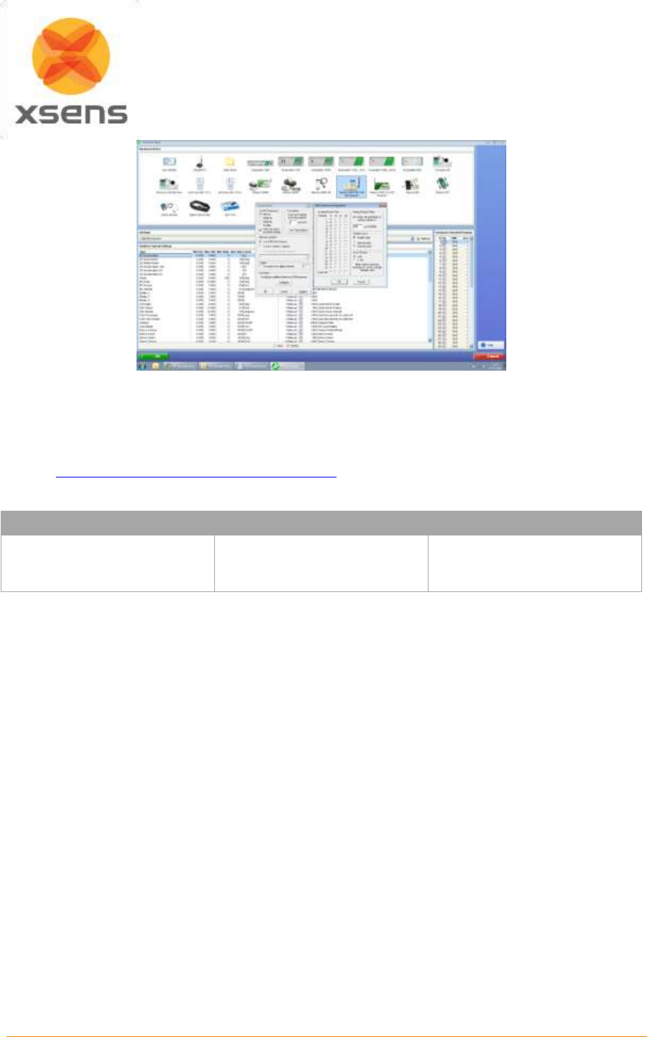
Document MV0319P.N
© Xsens Technologies B.V.
MVN User Manual
151
The rest of the software setup is as described in Section 23.7.3.6. However, instead of clicking Record
in MVN Studio, press the hardware trigger from Noraxon to generate a manual trigger to both systems.
23.8 More Synchronization Examples
Visit the Xsens website for synchronization examples of Xsens tried and tested with a number of third
party hardware systems. While these examples are currently on the MTw page, the parameters have
also been proven for MVN.
EMG
Pressure Mats
Optical Systems
Noraxon
Delsys
Cometa Wave
GAITRite
Vicon

Document MV0319P.N
© Xsens Technologies B.V.
MVN User Manual
152
24 References
i
Wu G, Cavanagh PR (1995). ISB recommendations for standardization in the reporting of kinematic data. J.
Biomech. 28: 1257-261
ii
Wu G., Siegler, S., Allard, P., Kirtley, C., Leardini, A., Rosenbaum, D., Whittle, M., D’Lima, D., Cristofolini, L.,
Witte, H., Schmid, O., Stokes, I., (2002). ISB recommendation on definitions of joint coordinate system of various
joints for the reporting of human joint motion—part I: ankle, hip, and spine. J. Biomech 35:543–548
iii
Wu G, van der Helm FC, Veeger HEJ, Makhsous M, van Roy P, Anglin C, Nagels J, Karduna A, Mc Quade K, Wang
X, Werner FW, Buchholz B (2005) ISB recommendation on definitions of joint coordinate systems of various joints
for the reporting of human joint motion—part II: shoulder, elbow, wrist and hand. J Biomech 38:981–992
iv
Della Croce U, Leardini A, Chiari L, Della Croce A. (2005) Human movement analysis using
stereophotogrammetry. Part 4: assessment of anatomical landmark misplacement and its effects on joint
kinematics; Gait & posture; vol. 21, no2, pp. 226-237
v
Šenk M, Cheze L. (2006) Rotation sequence as an important factor in shoulder kinematics. Clinical Biomechanics
21 S3 S8
vi
Grood, E.S., Suntay, W.J., (1983). A joint coordinate system for the clinical description of three-dimensional
motions: application to the knee. J. Biomechanical Engineering 105:136-144