Xsens Technologies AWNDDNG Wireless dongle User Manual Manual
Xsens Technologies B.V. Wireless dongle Manual
UserManual.wiki
>
Xsens Technologies
>
AWNDDNG User Manual
Manual
Navigation menu
Upload a User Manual
Namespaces
Wiki Guide
HTML
PDF
Info
Views
User Manual
Discussion / Help
Navigation


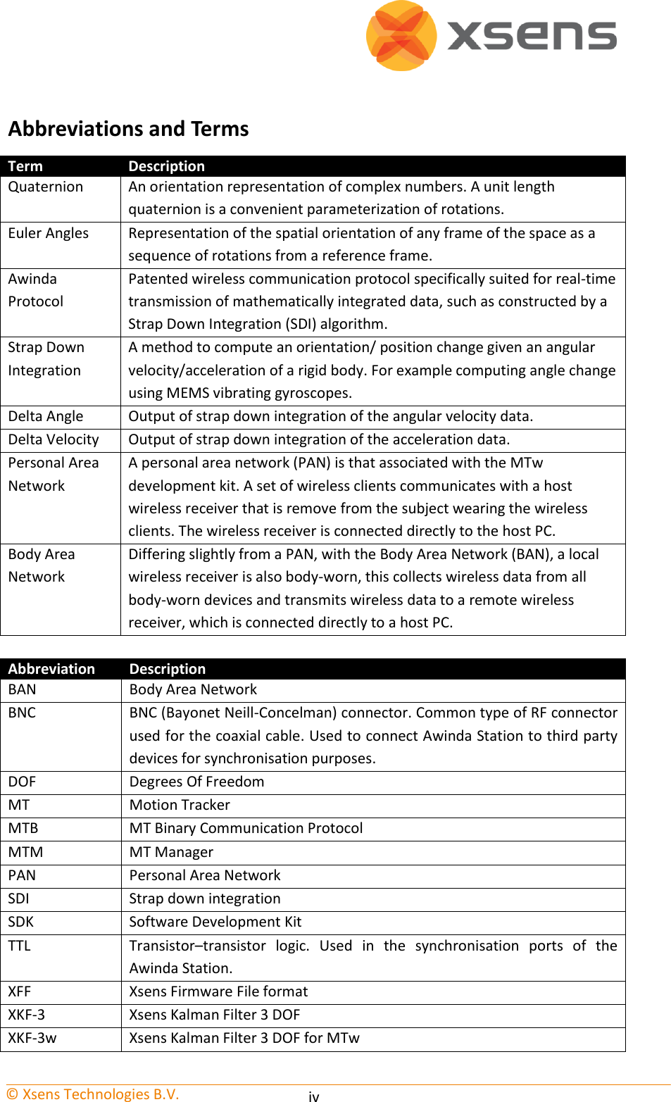

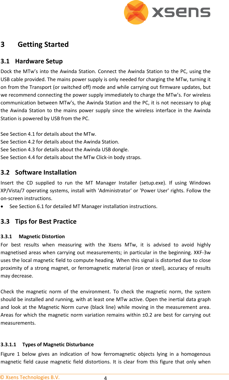


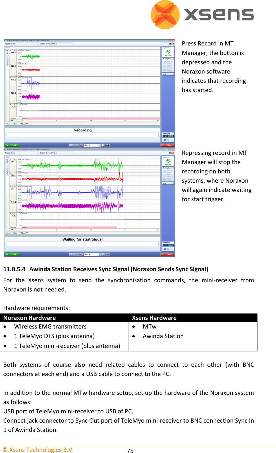
![© Xsens Technologies B.V. 9 4.1.1 MTw LED Indications The following lists the LED indications of the MTw, which are a combination of the device states and the Awinda protocol states of the MTw: State Description Power-up Blinking. Docked and fully charged ON Charging Slow fade from ON to OFF as a percentage [%] of battery status. A slow cycle means an almost full battery. A quick cycle means an almost empty battery. Scanning Pulsating. Connected Slow symmetric ON/OFF toggle in sync with Awinda Station (CONN LED). Measuring Fast symmetric ON/OFF toggle in sync with Awinda Station (CONN LED). Battery Low Quick Triple Pulses, overrides other states until charging again. Flushing Double pulse in sync with Awinda Station (CONN LED). Stand-by OFF. Blinks for 3 s, if a change in magnetic field has been detected, while searching for a radio connection. 4.1.2 MTw Stand-by Mode Following a wireless connection, the MTw is in operational or measurement mode. When the radio of the Awinda Master has been switched off, for longer than 30 seconds the MTw will enter stand-by mode. In this mode, the MTw will shut down its power, but monitor change in magnetic field every second. See below for exiting standby mode. 4.1.3 Exiting stand-by mode With MT SDK 3.8 instead of searching only for a wireless link, the MTw will monitor its magnetic field once every second. If the magnetic field has changed considerably, and there is a wireless link to an Awinda Master available, the MTw will automatically become active again. To bring the MTw back from stand-by to operational mode, reactivate the radio of the Awinda Master, and move the MTw; a simple 90 degree turn, or simply lifting it from the suit case to apply to the subject should be enough. As an alternative, this can also be done by changing the magnetic field around the MTw. Consider moving a pair of stainless steel scissors (NOT A MAGNET) over the MTw, to change the field and reactivate it.](https://usermanual.wiki/Xsens-Technologies/AWNDDNG/User-Guide-1951493-Page-15.png)
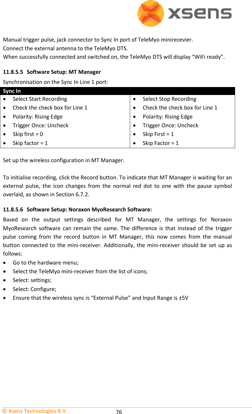
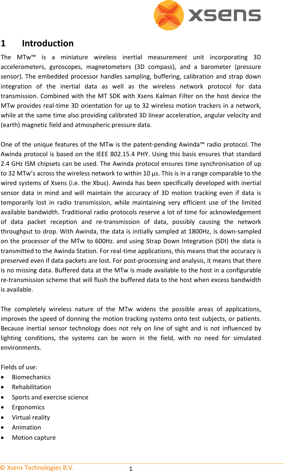
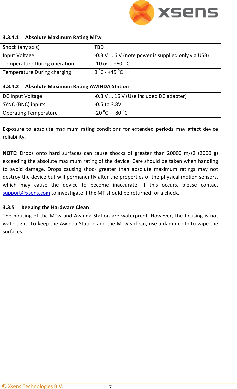
![© Xsens Technologies B.V. 10 4.1.4 Estimated battery life with stand-by mode activated Bat. Capacity at sleep start [%] Estimated time to full discharge in standby [hrs] Measuring time left after 8 hrs in standby [hrs:min] 100 88 2.18 75 64 1:45 50 44 1:06 25 20 0:24 10 8 0:00](https://usermanual.wiki/Xsens-Technologies/AWNDDNG/User-Guide-1951493-Page-16.png)
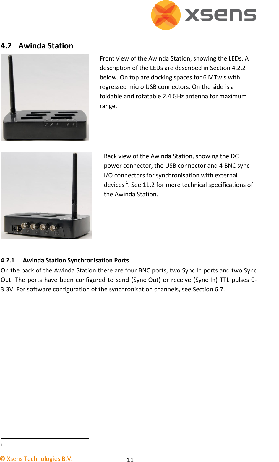
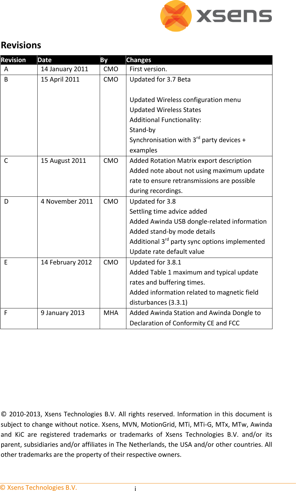
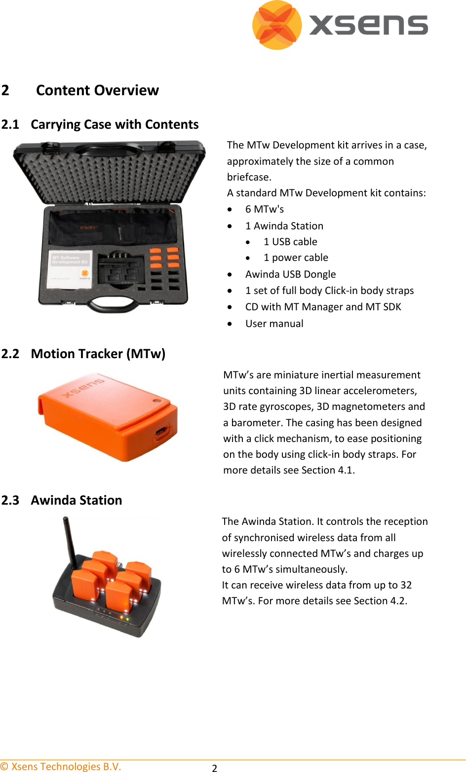
![© Xsens Technologies B.V. 12 4.2.2 Awinda Station Status LED The Awinda Station has five LED indicators. From right to left, these indicators are: LABEL LED DESCRIPTION CHRG [CHaRGer functionality] OFF When no mains power supply is connected to the Awinda Station. GREEN: When 12V power supply is connected (mains power supply). STAT [STATus of the Awinda Station] OFF OFF: When no USB connection is present and when MT Manager is not started. GREEN: Both USB connection present and MT Manager running connected to driver. ORANGE: USB connection to host PC is present. RED: Only power supply connected or error has occurred, e.g., a short-circuit of an MTw. EXT OFF Remains off unless external connection made. GREEN: External connection e.g. sync port. CONN OFF OFF: No wireless connection. GREEN slow blinking: (1 blink per second), radio switched on. When MTw connects, MTw LED and CONN LED blink synchronously. Fast blink: Measurement Mode. DATA OFF OFF: No data received. GREEN: Measurement mode. ORANGE: Flushing. Flushing is the action of transferring data that has been stored on the MTw buffer, while the MTw was out of range and unable to transfer data in real-time to the Awinda Station. RED: Recording mode is active. This allows the remote monitoring that the host PC has initiated a recording successfully. Note: The power supply is needed to charge the MTw’s or to change from power off to power on. Only the power supply is needed for charging purposes (USB is not needed in this case). Power supply and USB connection are required for firmware updates. Power supply is not needed for wireless communication (e.g. measurement/recording). 4.3 Awinda USB Dongle See 11.3 for more technical specifications of the Awinda USB Dongle.](https://usermanual.wiki/Xsens-Technologies/AWNDDNG/User-Guide-1951493-Page-18.png)


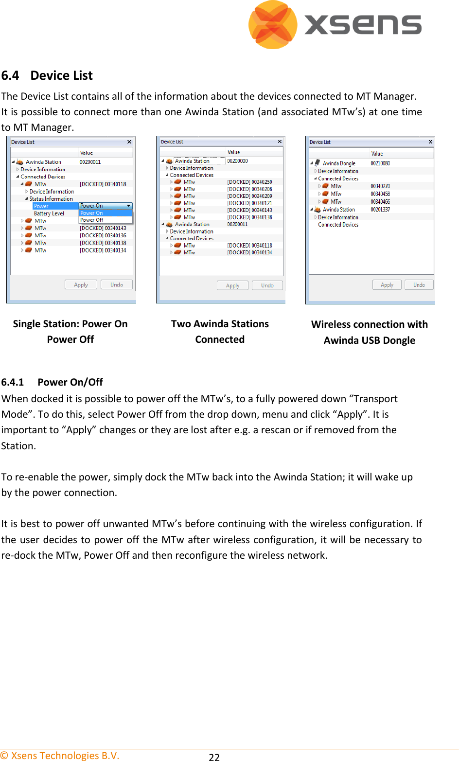
![© Xsens Technologies B.V. 23 When the wireless configuration has been performed, the Device List is updated such that all connected MTw’s are listed, with the indication of whether they are still in the Awinda Station (docked) or wirelessly connected. MTw’s docked or wirelessly connected is shown as a Connected Device in the Device List. Still docked (and not previously configured wirelessly) have the index “[DOCKED]”. 6.4.2 Location ID Users can change the numerical Location ID of docked MTw’s in the Device List. This is useful for example if users want to use a numerical code for a given body segment. After making changes in the Device List, click Apply to make sure changes are implemented.](https://usermanual.wiki/Xsens-Technologies/AWNDDNG/User-Guide-1951493-Page-29.png)
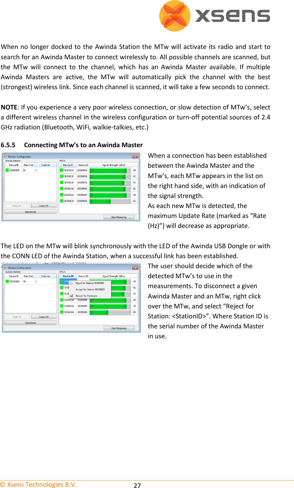
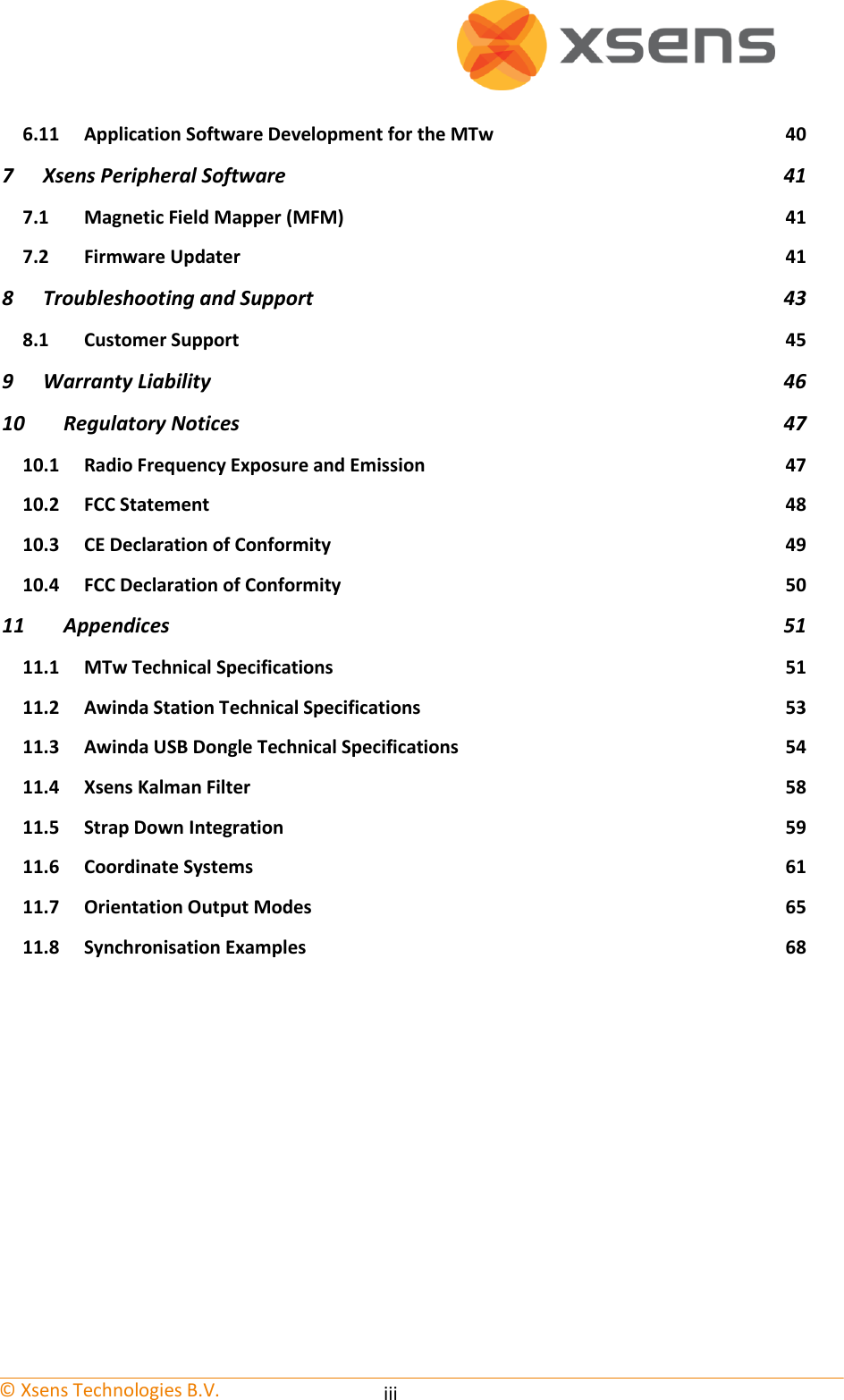
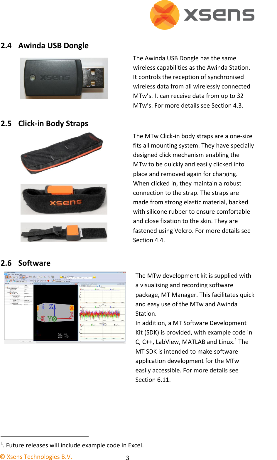
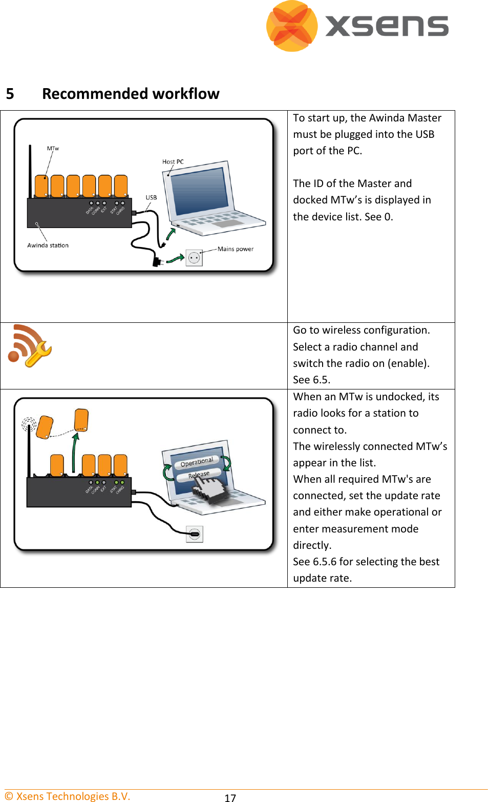
![© Xsens Technologies B.V. 28 Initially, if a user has rejected the MTw for a given station, this is depicted as “Unknown”. A rescan shows that the MTw was rejected by the user “Blacklisted”. To reconnect a rejected MTw and Awinda Master, right-click the MTw and select “Accept for Station: <Station ID>”. Rejecting an MTw does not cause it to power off; it stops communication between that MTw and the Awinda Master. NOTE: To power off the MTw, the user should power it off in the Device List, while docked in the Awinda Station, before starting the wireless configuration. See Section 6.4.1. 6.5.6 Update Rate As each MTw makes a connection with the Awinda Master, the Maximum Update Rate decreases accordingly. It is possible to select an update rate, by double clicking the value under “Rate (Hz)”, a drop down menu will appear with the available update rates. NOTE: The default update rate is always one value less than the maximum, to ensure that retransmissions are possible during recording. Users can increase this to maximum but caution should be taken as this will reduce or remove the possibility of retransmissions. Table 1 provides an indication of the maximum and typical update rates for a number of MTw’s. The buffering time is also indicated. This is the amount of time that data can be expected to be stored on the MTw, if the user goes beyond the specified radio transmission range. Table 1: Typical and maximum update rates and buffering times Amount of MTw’s UR [Hz] (max – no retransmissions) Buffering time[s] (max) UR [Hz] (typical – allowing retransmissions) Buffering Time [s] (typ) 1 150 7 120 9 2 120 9 100 10 4 100 10 75 14 6 75 14 60 17 12 50 20 40 26 18 40 26 30 34](https://usermanual.wiki/Xsens-Technologies/AWNDDNG/User-Guide-1951493-Page-34.png)
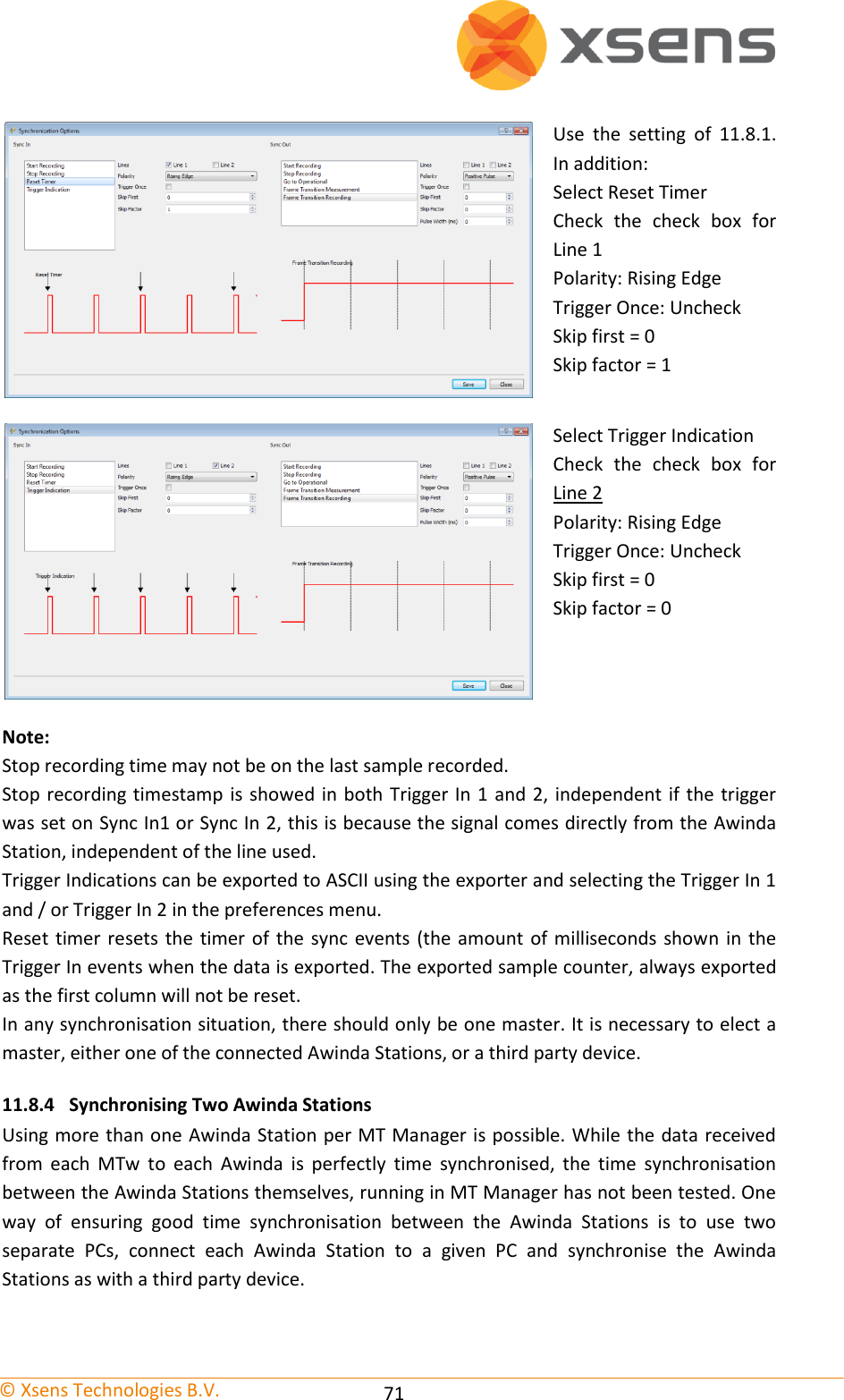
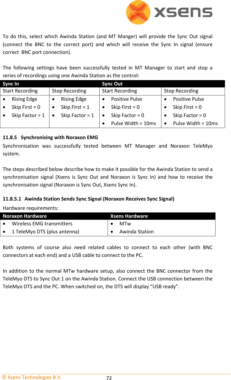
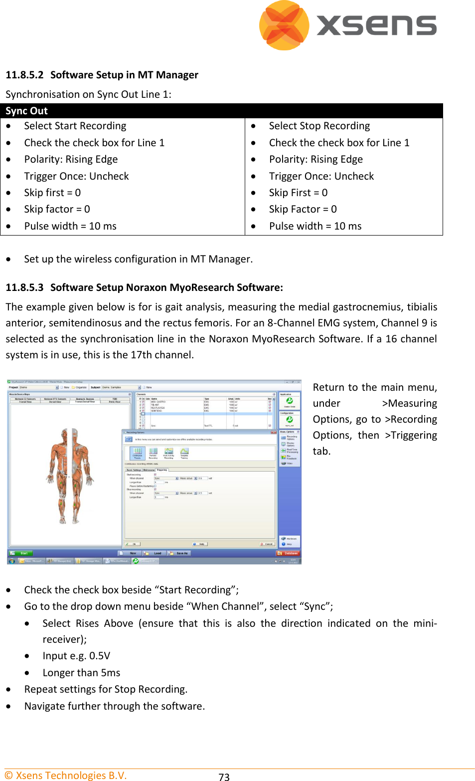
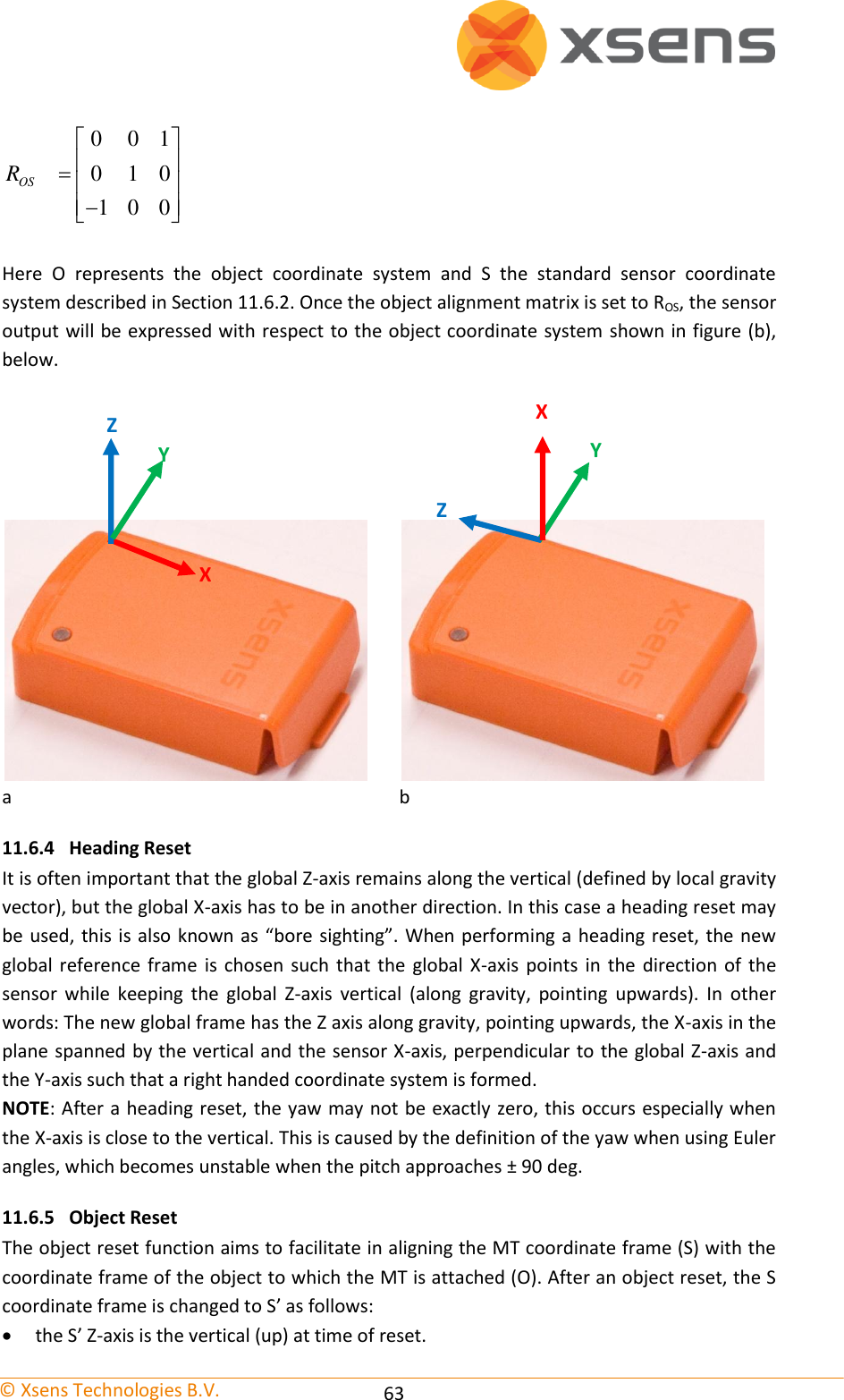
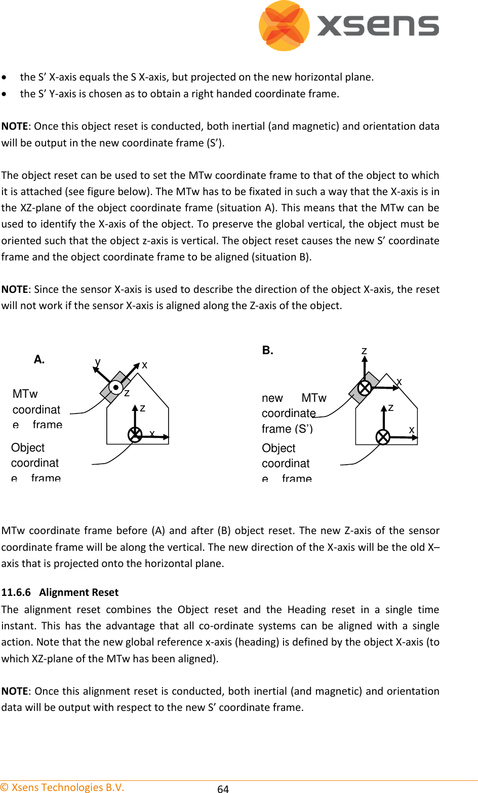
![© Xsens Technologies B.V. 36 Parameter Description Line The sync line to activate. Polarity Positive pulse (where the polarity is initially low [0V] and goes high [3.3V]). Negative pulse (where polarity is initially high [3.3V] and goes low [0V]). Trigger Once It is not recommended to selected Trigger once, if more than one recording using synchronisation of multiple systems will be made. Skip First Number of initial sync pulses to skip. This command is useful if a well-defined delay is expected between the Xsens and the third party system. It may also be needed if the third party, like the Xsens system uses the same pulse properties to trigger different actions. See description provided above for Sync In. Skip Factor Number of sync pulses, between the sync pulses delivered, to skip. See Sync In Table description. Pulse Width Some systems wait for a signal of a minimum pulse width before generating the desired synchronisation action. The Awinda Station can send a pulse with a duration of up to 99ms to a third party system. It is not recommended to send a signal longer than a frame width. Specify 0 ms to generate an infinite pulse width. 6.8 Orientation Reset In some situations, it may occur that the MTw sensor axes are not exactly aligned with the axes of the object of which the orientation has to be recorded. It may be desired to output the orientation and/or calibrated inertial (and magnetic) data in an object-fixed frame, as opposed to a sensor-fixed frame. Four methods have been added to the software to facilitate in obtaining the output in the desired coordinate frames. 1. Setting an arbitrary rotation matrix to rotate S to the chosen object coordinate system O. See Section 11.6.3. 2. A heading reset that redefines the X-axis of the global coordinate frame while maintaining the Z-axis along the vertical (also known as “boresighting”). After the heading reset the orientation will be expressed with respect to the new global (earth fixed) reference frame. See Section 11.6.4 3. An object reset that defines how the MTw is oriented with respect to the coordinate axes to which it is attached. After the object reset, both the inertial (and magnetic) and orientation data are expressed with respect to the axes of the object. See Section 11.6.5. 4. A combined object/heading reset, referred to as alignment. See Section 11.6.6. NOTE: For all co-ordinate system reset functions it is important to remember that the housing of the MTw cannot be considered an accurate reference. Placement and subsequent aligning must be done very carefully otherwise (alignment) errors may be induced.](https://usermanual.wiki/Xsens-Technologies/AWNDDNG/User-Guide-1951493-Page-42.png)
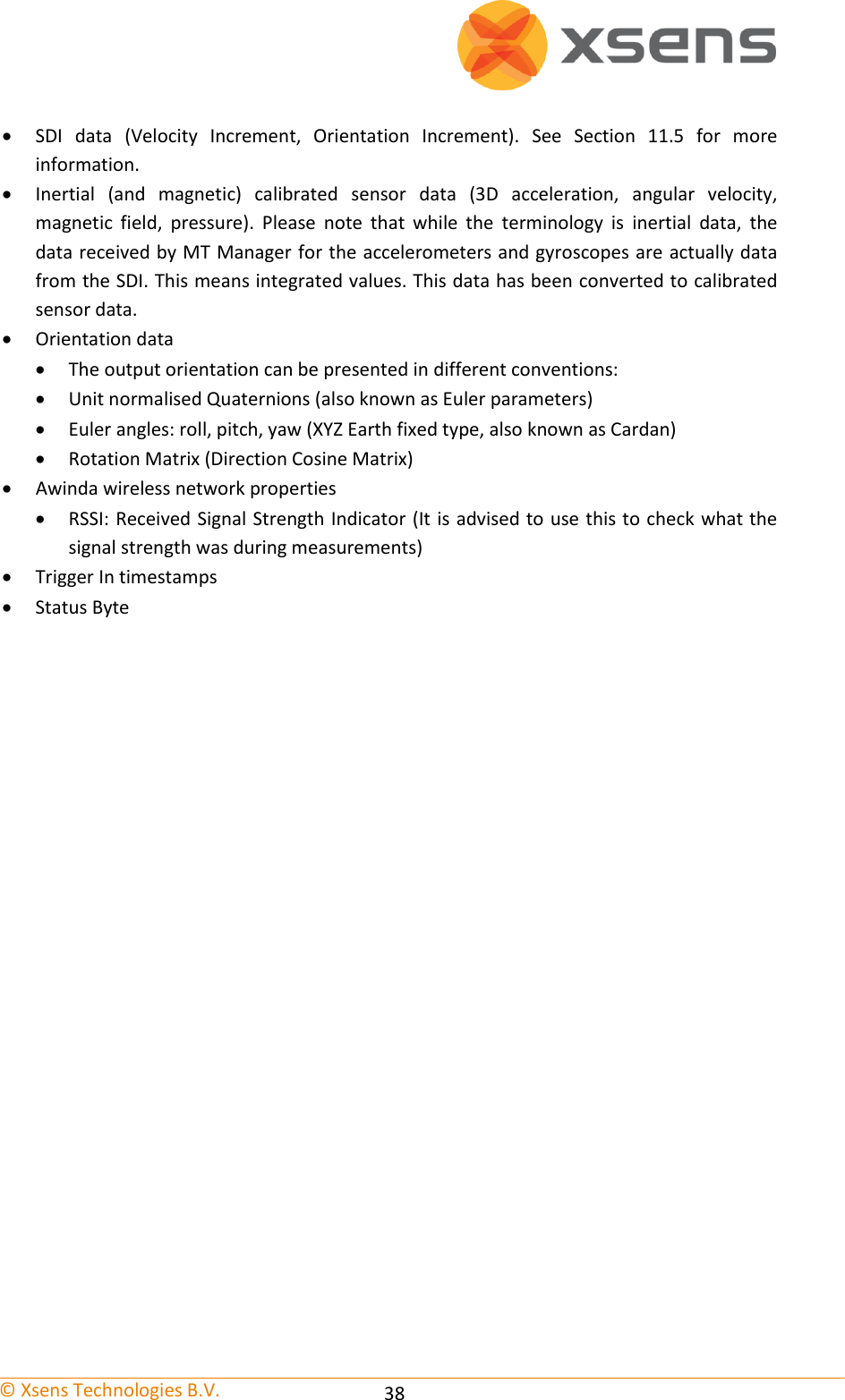
![© Xsens Technologies B.V. 39 Abbreviation Data Unit Counter Sample counter (-), wraps at 65535 Temperature Temperature inside housing o C VelInc_X Velocity increment from SDI, x-axis m/s VelInc_Y Velocity increment from SDI, y-axis m/s VelInc_Z Velocity increment from SDI, z-axis m/s OriInc_w Orientation increment quaternion from SDI, real component Unit quaternion OriInc_x Orientation increment quaternion from SDI, x-axis Unit quaternion OriInc_y Orientation increment quaternion from SDI, y-axis Unit quaternion OriInc_z Orientation increment quaternion from SDI, z-axis Unit quaternion Acc_X Acceleration x-axis m/s2 Acc_Y Acceleration y-axis m/s2 Acc_Z Acceleration z-axis m/s2 Gyr_X Angular rate x-axis rad/s Gyr_Y Angular rate y-axis rad/s Gyr_Z Angular rate z-axis rad/s Mag_X Magnetic field x-axis arbitrary unit; magnetic field strength at Xsens is 1 Mag_Y Magnetic field y-axis arbitrary unit; magnetic field strength at Xsens is 1 Mag_Z Magnetic field z-axis arbitrary unit; magnetic field strength at Xsens is 1 Pressure Atmospheric pressure mBar Roll/Pitch/Yaw Orientation Euler angles format (3) deg Quat * Orientation quaternion format (4) Unit quaternion Mat [R#][C#] Rotation matrix format [Row][Column] (3x3). (Direction Cosine matrix) Unit vectors Trigger In 1 Awinda converted time stamp values of trigger indications sent to Sync In 1 of the Awinda Station Milliseconds Trigger In 2 Awinda converted time stamp values of trigger indications sent to Sync In 2 of the Awinda Station Milliseconds Status N/A for MTw and / or MT SDK 3.7 Beta RSSI Received Signal Strength Indicator by Station dBm](https://usermanual.wiki/Xsens-Technologies/AWNDDNG/User-Guide-1951493-Page-45.png)


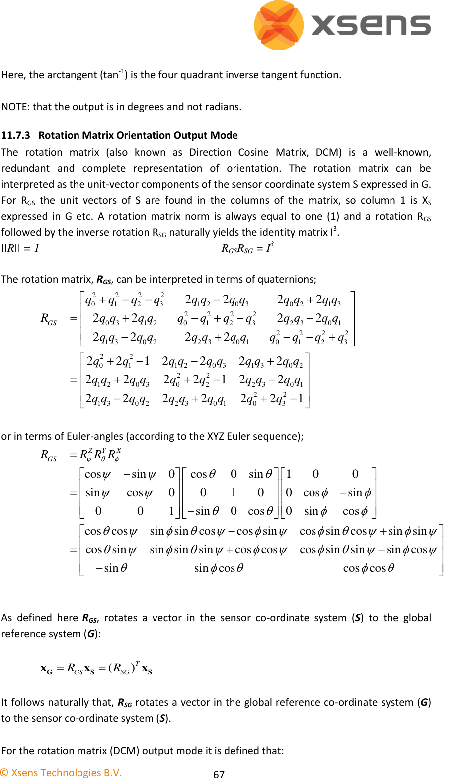
![© Xsens Technologies B.V. 66 The inverse (qSG) is defined by the complex conjugate (†) of qGS. The complex conjugate can be calculated: †0 1 2 3( , , , )GS SGq q q q q q As defined here qGS rotates a vector in the sensor co-ordinate system (S) to the global reference co-ordinate system (G). †GS GS GS SGq q q qG S Sx x x Hence, qSG rotates a vector in the global reference co-ordinate system (G) to the sensor co-ordinate system (S), where qSG is the complex conjugate of qGS. 11.7.2 Euler Angles Orientation Output Mode The definition used for 'Euler-angles' here is equivalent to 'roll, pitch, yaw/heading' (also known as Cardan). The Euler-angles as orientation output are provided as XYZ Earth fixed type (subsequent rotation around global X, Y and Z axis, also known as aerospace sequence). φ = roll1 = rotation around XG, defined from [-180o…180 o] θ = pitch2 = rotation around YG, defined from [-90 o …90 o] ψ = yaw3 = rotation around ZG, defined from [-180 o …180 o] NOTE: Due to the definition of Euler angles there is a mathematical singularity (gimbal lock) when the sensor-fixed X-axis is pointing up or down in the earth-fixed reference frame (i.e. pitch approaches ±90o). This singularity is in no way present in the quaternion or rotation matrix output mode. The singularity cannot be compensated for but only avoided using the rotation matrix output, then manually extract Euler Angles by using different Euler sequences4. The Euler-angles can be interpreted in terms of the components of the rotation matrix, RGS, or in terms of the unit quaternion, qGS; 1132 2 3 0 12233 0 31131 1 3 0 2111 2 0 3212211 0 122tan tan 2 2 1sin ( ) sin (2 2 )22tan tan 2 2 1GSGSGSR q q q qR q qR q q q qq q q qRR q q 1 “roll” is also known as: “bank” 2 “pitch” is also known as: “elevation” or “tilt” 3 “yaw” is also known as: “heading”, “pan” or “azimuth” 4 Woltring HJ. 3-D attitude representation of human joints: A standardization proposal. Journal of Biomechanics. 1994;27 (12):1399-1414.](https://usermanual.wiki/Xsens-Technologies/AWNDDNG/User-Guide-1951493-Page-72.png)