Y CAM SOLUTIONS YCBLHD6 802.11b/g/n (1T1R) WiFi Module User Manual Manual
Y-CAM SOLUTIONS LTD. 802.11b/g/n (1T1R) WiFi Module Manual
Manual
LP-8627M
802.11 B/G/N(1T1R) Wifi module
USER MANUAL 1.0.0
© 2012
1. Overview
LP-8627M Wireless LAN USB Module is a perfect combination of both
performance and cost-effective product introduced. It is sincerely hoped that
you can enjoy the wireless world through this solidly profiled wireless adapter.
It provides a full solution of all the IEEE 802.11 b/g/n protocols, that pass the
WiFi tests and are compatible with all the wireless products with WiFi logo. If
you have a Wireless LAN USB Module on hand, it means you can connect to
the wireless world without any difficulty. Since the security issue has become
one of the most important one in the wireless society, it provides you with the
full security coverage from the 64/128bits WEP encryptions, second
generation WPA-PSK encryption, to the most advanced WPA2-AES encryption.
WPA2 is the latest security standard currently approved by WiFi standards.

2. Product Spec
Standards IEEE802.11b/g/n
Antenna interface IPEX connector
Chip Set Realtek RTL8188CUS
Frequency Band 2.400~2.484 GHz unlicensed ISM band
Modulation Technology Orthogonal frequency division multiplexing(OFDM), Direct
Sequence Spread Spectrum(PBCC,CCK,DQPSK, DBPSK)
Data Rate
802.11b:11,5.5,2 and 1 Mbps with auto-rate fall back
802.11g:54,48,36,24,18,12,9 & 6 Mbps
802.11n:(20MHz) :up to 72 Mbps
802.11n:(40MHz) :up to 150 Mbps
Sensitivity -94dBm @802.11b/-88dbm @802.11g/-88dbm @802.11n
Security 64/128 bit WEP/WPA/WPA2(TKIP/AES)
Driver support Windows ® XP 32/64, Vista 32/64,Win 7 32/64
Working mode Infrastructure/Ad-Hoc/Soft AP
Operation Voltage 5V DC or 3.3V DC
Host Interface USB 2.0 / 6 Pins header
Frequency Stability <±5ppm @ Room Temperature +25℃
OFDM Output Power 15dBm (Typ.) @EVM<3%, all channel
CCK Spectral Mask
@Pout=18dBm -37dBc (Typ.) @ 11~22MHz -60dBc (Typ.) @ 22~33MHz
2f Harmonics -55dBm (Typ.)
LO Leakage Peak Power -64dBm (Typ.) @Transmit State
Receiver sensitivity
(PER<10%)
-65dBm [Typ.] @ HT40M, MCS7 -70dBm [Typ.] @ 54M, OFDM
-72dBm [Typ.] @ 11M, CCK -94dBm [Typ.] @ 1M, CCK
RF Port Impedance 50Ω±10%
USB Differential Port
Impedance 90Ω±10%
Temperatures(AMBIENT) Operation: 0℃~60℃, Storage:-20℃~70℃
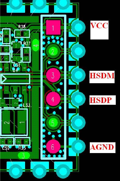
3. Pin Configurations
4. Software Installation
Step 1: Software Installation
Insert product CD to your PC. At the welcome screen, please click “Driver
Installation” to install the device driver & utility.
If you do not see the welcome screen, go to Start > My Computer and click to open
CD-ROM drive.
Then double click autorun.exe and wait a few seconds for the welcome screen to
show up.
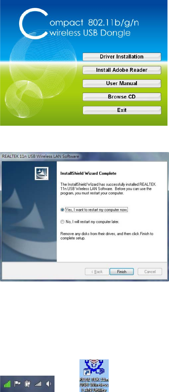
Step 2: Restart your computer
Once the installation is finished, click Finish button to restart your computer.
Step 3: Connect the USB adapter
Plug the USB Dongle into a USB port on your Laptop or Desktop computer.
Step 4: Connect to Wireless Network
To connect to a wireless network, double click on the Wireless Utility icon in the
system tray or on the desktop.
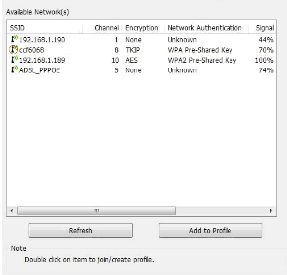
Icon in system Tray Icon on Desktop
Click on Available Network tab to view all the access points within range of the
adapter.
Double Click on the Access Point’s SSID to join the network. If the wireless Network
you selected requires security, the utility will guide you through the appropriate
security setup.
Available Network tab
After the signal strength is indicated, you have successfully set up your wireless
network on your PC or Laptop.
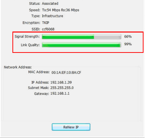
General tab
Unable to connect to a wireless network?
1. Ensure that the LEDs of your router are correctly lit.
Check whether your Wireless LAN settings (e.g. SSID, Channel Number) are
the same as the routers.
Check whether you use the same encryption key (e.g. WEP or WPA) for both
Dongle and the router.
2. Make sure that your USB Dongle is correctly installed.
Check that your Dongle is plugged in properly to the USB port or try to plug
the Dongle into another USB port if available.
The LED on Dongle should be lit. if not, (i) there could be a hardware
problem, or (ii) Dongle is disabled or (iii) device driver is not installed
properly.
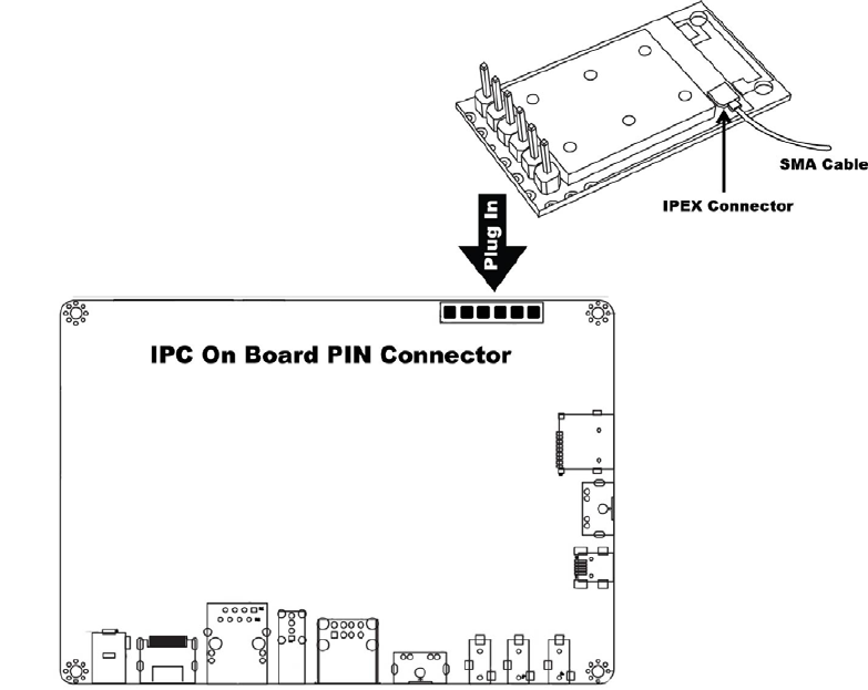
5. Hardware Installation
➢Connect the on board connector with pin header module.
Federal Communication Commission Statement (FCC, U.S.)
This equipment has been tested and found to comply with the limits for a Class B digital device, pursuant
to Part 15 of the FCC Rules. These limits are designed to provide reasonable protection against harmful
interference in a residential installation. This equipment generates, uses and can radiate radio frequency
energy and, if not installed and used in accordance with the instructions, may cause harmful interference
to radio communications. However, there is no guarantee that interference will not occur in a particular
installation. If this equipment does
cause harmful interference to radio or television reception, which can be determined by turning the
equipment off and on, the user is encouraged to try to correct the interference by one of the following
measures:
- Reorient or relocate the receiving antenna.
- Increase the separation between the equipment and receiver.
- Connect the equipment into an outlet on a circuit different from that to which the receiver is connected.
- Consult the dealer or an experienced radio/TV technician for help.
This device complies with Part 15 of the FCC Rules. Operation is subject to the following two conditions:
(1) This device may not cause harmful interference, and (2) this device must accept any interference
received, including interference that may cause undesired operation.
FCC Caution:
Any changes or modifications not expressly approved by the party responsible for compliance could void
the user's authority to operate this equipment.
IMPORTANT NOTES
FCC Radiation Exposure Statement:
This equipment complies with FCC radiation exposure limits set forth for an uncontrolled environment.
This equipment should be installed and operated with minimum distance 20cm between the radiator &
your body.
Co-location warning:
This transmitter must not be co-located or operating in conjunction with any other antenna or transmitter.
Limited Channels fixed for use in the US:
IEEE 802.11b or 802.11g or 802.11n(HT20, HT40) operation of this product in the U.S. is firmware-limited
to Channel 1 through 11.
OEM integration instructions:
This device is intended only for OEM integrators under the following conditions:
The antenna must be installed such that 20 cm is maintained between the antenna and users, and the
transmitter module may not be co-located with any other transmitter or antenna. The module shall be only
used with the external antenna(s) that has been originally tested and certified with this module.
As long as 3 conditions above are met, further transmitter test will not be required. However, the OEM
integrator is still responsible for testing their end-product for any additional compliance requirements
required with this module installed (for example, digital device emissions, PC peripheral requirements,
etc.).
Validity of using the module certification:
In the event that these conditions cannot be met (for example certain laptop configurations or co-location
with another transmitter), then the FCC authorization for this module in combination with the host
equipment is no longer considered valid and the FCC ID of the module cannot be used on the final
product. In these circumstances, the OEM integrator will be responsible for re-evaluating the end product
(including the transmitter) and obtaining a separate FCC authorization.
Custom design antennas may be used, however the OEM installer must following the FCC 15.21
requirements and verify if new FCC approval will be necessary.
End product labeling:
This transmitter module is authorized only for use in device where the antenna may be installed such that
20 cm may be maintained between the antenna and users. The final end product must be labeled in a
visible area with the following:
“Contains FCC ID: V4FYCBLHD6”.
Information that must be placed in the end user manual:
The OEM integrator has to be aware not to provide information to the end user regarding how to install or
remove this RF module in the user's manual of the end product which integrates this module. The end
user manual shall include all required regulatory information/warning as show in this manual.