YAMAHA Receivers Manual L0522708
User Manual: YAMAHA YAMAHA Receivers Manual YAMAHA Receivers Owner's Manual, YAMAHA Receivers installation guides
Open the PDF directly: View PDF ![]() .
.
Page Count: 107 [warning: Documents this large are best viewed by clicking the View PDF Link!]
OWNER'S MANUAL
CAUTION
RISKOFELECTRICSHOCK
DONOTOPEN
CAUTION: TO REDUCE THE RISK OF
ELECTRIC SHOCK, DO NOT REMOVE
COVER (OR BACK). NO USER-SERVICEABLE
PARTS INSIDE. REFER SERVICING TO
QUALIFIED SERVICE PERSONNEL.
• Explanation of Graphical Symbols
The lightning flash with arrowhead symbol, within an
equilaleral triangle,is intendedto alert you to the
prc_nce of uninsulated 'dangerous voltage" within
the produces enclosure that may be of suiiicienl
magnitude to constitute a risk of electric shockto
persons.
The exclamatkm poinl within an equilatcral triangle
is inlendedto ale]t you 1othe prc_nce of important
operating and maintenance/servicing) instructkms in
the literature accompanying the appliance.
1 Read Instructiotts All the safety and operating iustructions
should be read before the product is operated.
2 Retain Iustructious The safety and operating instructions
should be retaiued for future reference.
3Heed Warniugs All warnings ou the product aud iu the
operating instructions should be adhered to.
4Follow Instructions All operating and use instructions
should be followed.
5 Cleauing Uuplug this product from the wall outlet before
cleaning. Do not use liqukl cleaners or aerosol cleaners. Use
a damp cloth for cleaning.
6 Attachments Do uot use attachmeuts not recommended by
the product manufacturer as they may cause hazards.
7 Water aud Moisture Do not use this product uear water
for example, near a bath tub. wash bowl. kitcheu siuk. or
laundry tub: in a wet basement: or near a switnming pool:
and the like.
8 Accessories Do uot place this product on an unstable cart.
staud, tripod, bracket, or table. The product may fall.
causing serious iujury to a child or adult, aud serious
damage to the product. Use only with a cart. staud, tripod.
bracket, or table recommeuded by the tnauufacturer, or sold
with the product. Auy tnouuting of the product should
follow the tnanufacturer's iustructions, and should use a
mouuting accessory recommeuded by the mauufacturer.
9 A product and cart combination should be moved with care.
Quick stops, excessive force, and uueven
surfaces may cause the product and cart
conlbiuatiou to overturn.
10 Ventilation Slots aud openings iu the cabinet are provided
for ventilation aud to ensure reliable operatiou of the
product and to protect it from overheating, aud these
opeuings tnust uot be blocked or covered. The openiugs
should uever be blocked by placiug the product on a bed.
sofa. rug, or other similar surface. This product should not
be placed ill a built-in installation such as a bookcase or rack
unless proper ventilation is provided or the manufacturer's
instructions have been adhered to.
11 Power Sources This product should be operated only from
the type of power source iudicated on the markiug labeh If
you are not sure of the type of power supply to your home.
cousult your product dealer or local power company. For
products iuteuded to operate from battery power, or other
sources, refer to the operatiug instructions.
12 Grouudiug or Polarization This product may be equipped
with a polarized alteruating current lille plug (a plug having
oue blade wider thau the other). This plug will fit iuto the
power outlet ouly one way. This is a safety feature. If you
are unable to insert the plug fully into the outlet, try
reversing the plug. If the plug should still fail to fit. contact
your electrician to replace your obsolete outlet. Do uot
defeat the safety purpose of the polarized plug.
1:3 Power-Cord Protectiou Power-supply cords should be
routed so that they are not likely to be walked on or pinched
by items placed upon or against them, paying particular
atteution to cords at plugs, convenience receptacles, and the
poiut where they exit from the product.
14 Liglltuiug For added protection for this product during a
lightning storm, or when it is left unattended aud unused for
long periods of tithe, uuplug it from the wall outlet and
disconnect the autenna or cable system. This will prevent
damage to the product due to lightning aud power-liue
surges.
15 Power Liues Au outside antenua system should not be
located in the viciuity of overhead power liues or other
electric light or power circuits, or where it cau fN1 into such
power lines or circuits. Wheu installiug all outside autenna
system, extreme care should be takeu to keep from touching
such power liues or circuits as contact with them tnight be
fatal.
16 Overloadiug Do not overload wall outlets, extensiou
cords, or integral convenieuce receptacles as this call result
ill a risk of fire or electric shock.
17 Object and Liquid Eutry Never push objects of any kind
into this product through openiugs as they may touch
daugerous voltage points or short-out parts that could result
in a fire or electric shock. Never spill liquid of auy kiud on
the product.
18 Servicing Do not attempt to service this product yourself
its opeuiug or removiug covers may expose you to
dangerous voltage or other hazards. Refer N1 servicing to
qualified service personneh
19 Damage Requiring Service Unphlg this product from the
wall outlet and refer servicing to qualified service personnel
under the following couditious:
a) When the power-supply cord or plug is damaged,
b) If liquid has been spilled, or objects have fallen into the
product.
c/ If the product has beeu exposed to rain or water.
d) Iftileproductdoesnotoperatenormallyby%llowing 24
tile operaling instructions. Atljust only those controls
that are covered by the operating instructions as an
improper a;ljustmeot of other controls may result in
damage and will often require extensive work by a
qualified technician to restore the product to its normal
operation.
e) If the product has been dropped or damaged in any
way, and
f) When the product exhibits a distinct change in perfor-
mance - this indicales a need for service.
20 Replacement Parts When replacement parts are required.
be sure the service technician has used replacement parts
specified by the mauufi_cturer or have the same
characteristics as the original part. Unauthorized
substitutions may result in fire. electric shock, or other
hazards.
21 Safely Check Upon complelion of any service or repairs Io
Ihis producL ask tile service lechnician I(! perform safety /
checks to delermiue Ihal tile product is in proper operating
condition.
22 Wall or Ceiling Mounting Tile unit shoukl be mounted
to a wall or ceiling only as recommended by tile
manufacturer.
ELECTRIC
23 Heat The product should be situated away from heat se_wcE
sources such as radiators, heat registers, stoves, or other
products (including amplifiers) that produce heat.
Note to CATV system installer:
This reminder is provided to call the CATV system installer's
attention to Article 820-40 of the NEC that provides
guidelines for proper grounding and, in particular, specifies
that the cable ground shall be commcted to the grounding
system of the buikling, as close to the point of cable entry as
practicah
ri_l.g,]:_lt'Zf_TBl_,,,yZf._.lll,ml_Tt,.,jfl;t#imjflffO]LT_--
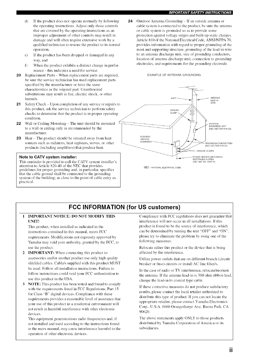
Outdoor Antenna Grounding If an outside antenna or
cable system is commcted to the product, be sure the antemm
or cable system is grounded so as to provide some
protection against voltage surges and built-up static charges.
Article S10 of the National Electrical Code. ANSI/NFPA 7().
provides information with regard to proper grounding of the
mast and supporting structure, grounding of tile lead-in wire
to an autemla discharge unit. size of grounding conductors.
location of antmma discharge unit. ccmnection to grounding
electrodes, and requirements for the grounding electrode.
EXAMPLE OF ANTENNA GROUNDING
NEC NATIONAL ELECTRICAL CODE
FCC INFORMATION (for US customers)
1IMPORTANT NOTICE: DO NOT MODIFY THIS
UNIT!
This product, when installed as indicated in tile
instructions contained in this manual, meets FCC
requirements. Modifications not expressly approved by
Yamaha may void your authority, granted by tile FCC. to
use the product.
2 IMPORTANT: When comlectiug this product to
accessories and/or another product use only high quality
shielded cables. Cable/s supplied with this product MUST
be used. Follow all installation instructions. Failure to
follow instructions could void your FCC authorization to
use this product in the USA.
3 NOTE: This product has been tested and found to comply
with the requirements listed in FCC Regulations. Part 15
for Class "B" digital devices. Compliance with these
requirements provkles a reasonable level of assurance that
your use of this product in a residential environment will
not result in harmful interference with other electronic
devices.
This equipment generates/uses radio frequencies and. if
not installed and used according to the instructions found
in the users manual, may cause interference harmful to the
operation of other electronic devices.
Compliance with FCC regulations does not guarantee that
interference will not occur in all installations. If this
product is found to be the source of interference, which
can be determined by turning the unit "OFF" and "ON".
please try to eliminate the problem by using one of the
following measures:
Relocate either this product or the device that is being
affected by the interference.
Utilize power outlets that are on different branch (circuit
breaker or fuse) circuits or install AC line filter/s.
In the case of radio or TV interference, relocate/reorient
the antenna. If the antenna leadqn is 300 ohm ribbon lead
change the lead-in to coaxial type cable.
If these corrective measures do not produce satisfactory
results, please contact the local retailer authorized to
distribute this type of product. If you can not locate the
appropriate retailer, please contact Yamaha Electronics
Corp.. U.S.A. 6660 Orangethorpe Ave. Buena Park. CA
90620.
The above statements apply ONLY to those products
distributed by Yamaha Corporation of America or its
subsidiaries.
1 To assure the finest performance, please read this
manual carefully. Keep it in a safe place for future
reference.
2 Install this sound system in a well ventilated, cool,
dry, clean place - away from direct sunlight, heat
sources, vibration, dust, moisture, and/or cold.
Allow ventilation space of at least 30 cm on the top,
20 cm on the left and right, and 20 cm on the back of
this unit.
3 Locate this unit away from other electrical
appliances, motors, or transformers to avoid
humming sounds.
4 Do not expose this unit to sudden temperature
changes from cold to hot, and do not locate this unit
in a environment with high humidity (i.e. a room with
a humidifier) to prevent condensation inside this
unit, which may cause an electrical shock, fire,
damage to this unit, and/or personal injury.
5 Avoid installing this unit where foreign object may
fall onto this unit and/or this unit may be exposed to
liquid dripping or splashing. On the top of this unit,
do not place:
- Other components, as they may cause damage
and/or discoloration on the surface of this unit.
- Burning objects (i.e. candles), as they may cause
fire, damage to this unit, and/or personal injury.
- Containers with liquid in them, as they may fall
and liquid may cause electrical shock to the user
and/or damage to this unit.
6 Do not cover this unit with a newspaper, tablecloth,
curtain, etc. in order not to obstruct heat radiation. If
the temperature inside this unit rises, it may cause
fire, damage to this unit, and/or personal injury.
7 Do not plug in this unit to a wall outlet until all
connections are complete.
8 Do not operate this unit upside-down. It may
overheat, possibly causing damage.
9 Do not use force on switches, knobs and/or cords.
10 When disconnecting the power cord from the wall
outlet, grasp the plug; do not pull the cord.
11 Do not clean this unit with chemical solvents; this
might damage the finish. Use a clean, dry cloth.
12 Only voltage specified on this unit must be used.
Using this unit with a higher voltage than specified
is dangerous and may cause fire, damage to this
unit, and/or personal injury. YAMAHA will not be
held responsible for any damage resulting from use
of this unit with a voltage other than specified.
13 To prevent damage by lightning, disconnect the
power cord and outdoor antenna from the wall outlet
during an electrical storm.
We Want You Listening For A Lifetime
14 Do not attempt to modify or fix this unit. Contact
qualified YAMAHA service personnel when any
service is needed. The cabinet should never be
opened for any reasons.
15 When not planning to use this unit for long periods
of time (i.e. vacation), disconnect the AC power plug
from the wall outlet.
16 Be sure to read the "TROUBLESHOOTING" section
on common operating errors before concluding that
this unit is faulty.
17 Before moving this unit, press STANDBY/ON to set
this unit in the standby mode, and disconnect the
AC power plug from the wall outlet.
18 VOLTAGE SELECTOR (Asia and General models
only)
The VOLTAGE SELECTOR on the rear panel of this
unit must be set for your local main voltage BEFORE
plugging into the AC main supply. Voltages are:
Asia model ..................... 220/230-240 V AC, 50/60 Hz
General model
............................ 110/120/220/230-240 V AC, 50/60 Hz
WARNING
TO REDUCE THE RISK OF FIRE OR ELECTRIC
SHOCK, DO NOT EXPOSE THIS UNIT TO RAIN
OR MOISTURE.
This unit is not disconnected from the AC po'_,er
source as long as it is connected to the "_,all outlet,
even if this unit itself is turned oft'. This state is called
the standby mode. In this state, this unit is designed to
consume a very small quantity of power.
FOR CANADIAN CUSTOMERS
To prevent electric shock, match w,ide blade of plug to
wide slot and fully insert.
This Class B digital apparatus complies with Canadian
ICES-003.
IMPORTANT
Please record tile serial number of this unit in the space
below.
MODEL:
Serial No.:
The serial nnmber is located on the rear of the unit.
Retain this Owner's Manual in a safe place for fimlre
reference.
YAMAHA and the Electronic Industries Association's Consumer
Electronics Group want ynu to get the most nut of your equipment
by playing it at a safe level. One that lets the snund come through
loud and clear without annoying blaring or distortion and. most
importantly, without affecting your sensitive hearing.
Since hearing danmge fi'om lnnd sounds is nflen
undeteclable until il is tno ]ale, YAMAHA and the
Eleclrnnic lnduslries Associalion's Cnnsumer
Eleclrnnics (lroup recnnmlend ynu Io avoid
prolnnged expnsure from excessive vnlnme levels. L}ST_>_}N_
===
III
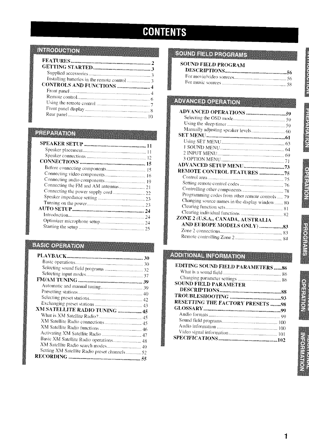
FEATURES ............................................................. 2
GETTING STARTED ............................................ 3
Supplied accessories .................................................. 3
h/stalling batteries in the remote control ................... 3
CONTROLS AND FUNCTIONS ......................... 4
Front paael ................................................................. 4
Remote control ........................................................... 6
Using the remote control ........................................... 7
Front panel display .................................................... 8
Rea panel ................................................................ l0
SPEAKER SETUP ............................................... 11
Speaker placement ................................................... 11
Speaker colluec'tiolls ................................................ ] 2
CONNECTIONS .................................................. 15
Before cuunecting components ................................ 15
Connecting video components ................................. 16
Connecting audio components ................................. 19
Connecting the FM and AM antennas ..................... 21
Connecting the power supply cord .......................... 22
Speaker impedance setting ...................................... 23
Turning ol) the power ............................................... 23
AUTO SETUP ....................................................... 24
Introduction .............................................................. 24
Optimizer microphone setup .................................... 24
Starting the setup ..................................................... 25
PLAYBACK .......................................................... 30
Basic operations ....................................................... 30
Selectitlg sound field programs ............................... 32
Sdecting input modes .............................................. 37
FM/AM TUNING ................................................. 39
Automatic and manual tuning .................................. 39
Presetting stations .................................................... 40
Selecting preset stations ........................................... 42
E×changiug preset stations ...................................... 43
XM SATELLITE RADIO TUNING .................. 45
What is XM Satellite Radio? ................................... 45
XM Satellite Radio connections .............................. 45
XM Satellile Radio functions .................................. 46
Activating XM Satellite Radio ................................ 47
Basic XM Satellite Radio operations ....................... 48
XM Salelli{e Radio search modes ............................ 49
Setting XM Satellfle Radio preset channels ............ 52
RECORDING ....................................................... 55
For mu__ ................ 58
ADVANCED OPERATIONS .............................. 59
Selecting the OSD mode .......................................... 59
Using the sleep timer ............................................... 59
Manually adjusting speaker levels ........................... 60
SET MENI.I ............................................................ 61
Using SET MENU ................................................... 63
l SOUND MENU .................................................... 6_,
2 INPUT MENU ...................................................... 69
3OPTION MENU ................................................... 71
ADVANCED SETUP MENU ............................... 73
REMOTE CONTROL FEATURES ................... 75
Control area ............................................................. 75
Setling remo(e conlrol codes ................................... 76
Coulrolliug other culnpouenls ................................. 78
Programming codes from other remote coutro/s ..... 79
Changing source names ia the display window ....... 80
Clearing function sets .............................................. 8 I
Clearing individual functiorJs .................................. 82
ZONE 2 (U.S.A., CANADA, AUSTRALIA
AND EUROPE MODELS ONLY) .................. 83
Zone 2 connections .................................................. 83
Remote controlling Zone 2 ...................................... 8.4
EDITING SOUND FIELD PARAMETERS ...... 86
What is a sound field ............................................... 86
Ch:mging parmneter settings ................................... 86
SOUND FIELD PARAMETER
DESCRIPTIONS ............................................... 88
TROUBLESHOOTING ....................................... 93
RESETTING THE FACTORY PRESETS ........ 98
GLOSSARY ........................................................... 99
Audio formats .......................................................... 99
Sound field programs ............................................. 100
Audio information ................................................. 100
Video signal information ....................................... 101
SPECIFICATIONS ............................................. 102
Built-in 7-channel power amplifier
• Miuimmn RMS output po'a.er
(0.06% THD, 20 Hz to 20 kHz, 8 f_)
Front: 100 W + 100 W
Center: 100 W
Surround: 100 W +100 W
Surround back: 100 W + 100 W
Sound field features
• Proprietary YAMAHA technology for tile creation of
sound fieMs
• Dolby Digital/Dolby Digital EX decoder
• DTS/DTS-ES Matrix 6.1, Discrete 6.1 DTS Neo:6,
DTS 9(,/24 decoder
• Dolby Pro Logic/Dolby Pro Logic IX/
Dolby Pro Logic IIx decoder
• Virtual CINEMA DSP
• SILENT CINEMA TM
Sophisticated AM/FM tuner
• 40-station random and direct preset tnnmg
• Automatic preset tuning
• Preset station shifting capability (preset editing)
XM Satellite Radio
• XM Satellite Radio programming (using the "XM
connect and Play digital antenna accessory", sold
separately)
Other features
• YPAO: YAMAHA Parametric Room Acoustic
Optimizer for automatic speaker setup
• 192-kHz/24-bit D/A converter
• A SET MENU that provides yon with items for
optimizing this unit for your audio/video system
• 8 additional input jacks for discrete multi-channel input
• PURE DIRECT t_r pure fidelity sound with analog and
PCM sources
• On-screen display function helpfld in controlling this
unit
• S-video signal input/output capability
• Component video input/output capability
• Video signal conversion (Composite video 4-> S-video
--> Component video) capability for monitor out
• Optical and coaxial digital audio signal jacks
• Sleep timer
• Cinema and music night listening modes
• Remote control with preset remote control codes and
"learning" capability
• Zone 2 custom installation facility (U.S.A., Canada,
Australia and Europe models only)
• -"_;'-indicates a tip for your operation.
• Some operations can be perlk_rmed by using either the buttons on the main unit or on the remote controh In cases when the button
names differ between the main unit and the remote control, the button name on the remote control is given in parentheses.
• This manual is printed prior to production. Design and specifications are subject to change in part as a result of improvements, etc. In
case of differences between the manual and product, the product has priority.
DIGITAL, EN
Manufactured under license lhom Dolby Laboratories.
"Dolby', "Pro Logic". "Surround EX". and the double_D symbol
are trademarks of Dolby Laboratories.
SILENT '_
CINEMA
"SILENT CINEMA" is a trademark of YAMAHA
CORPORATION.
"DTS'. "DTS-ES'. "Neo:6" and "DTS 96/24" are trademarks of
Digital Theater Systems. Inc.
NA_
READY
The XM name and related logos are registered trademarks of XM
Satellite Radio Inc.
2
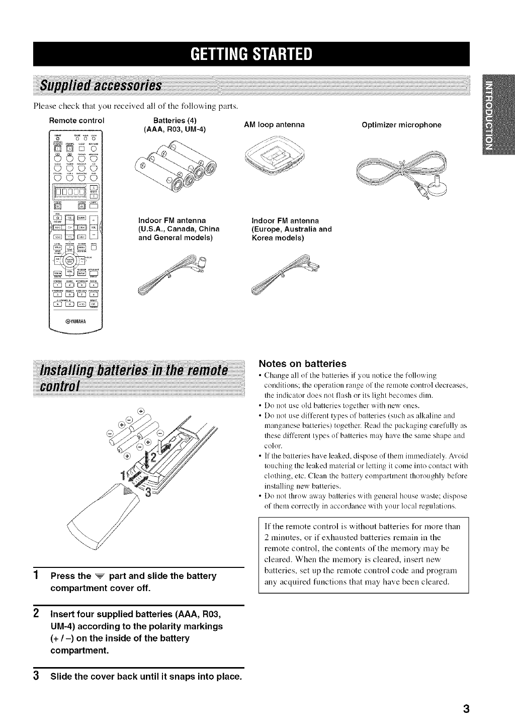
Please check that you received all of the following parts.
Remote control Batteries (4)
©C)©
{D'CANNtA
(AAA, R03, UM-4)
Indoor FM antenna
(U.S.A., Canada, China
and General models)
AM loop antenna
Indoor FM antenna
(Europe, Australia and
Korea models)
Optimizer microphone
aNN NNaNNaia
Press the _part and slide the battery
compartment cover off.
Insert four supplied batteries (AAA, R03,
UM-4) according to the polarity markings
(+/-) on the inside of the battery
compartment.
3 Slide the cover back until it snaps into place.
Notes on batteries
•Ch_mge :dl of the batteries it you notice the lollowing
conditions: tile operation range of the remote control decreases.
the indicator does not flash or its light becomes dim.
• Do not use old batteries together with new ones.
• Do not use different types of batteries (such as alkaline and
manganese batteries) together. Read the packaging carefully as
these different types of batteries m:q have the same shape and
color.
• If the batteries have leaked, dispose of them immediately. Avoid
touching the leaked material or letting it come into contact with
clothing, etc. Clean the battery compartment thoroughly bel'_re
installing new batteries.
• Do not throw :raay batteries with general house waste: dispose
of them correctly in accordance with your local regulations.
If the remote control is without batteries for more than
2 minntes, or if exhansted batteries remain in the
remote control, the contents of the memory may be
cleared. When the memory is cleared, insert new
batteries, set up the remote control code and program
any acqnired functions that may have been cleared.
3
(U.S.A. model
÷
(U.S.A., Canada,
Australia and Europe
models only)
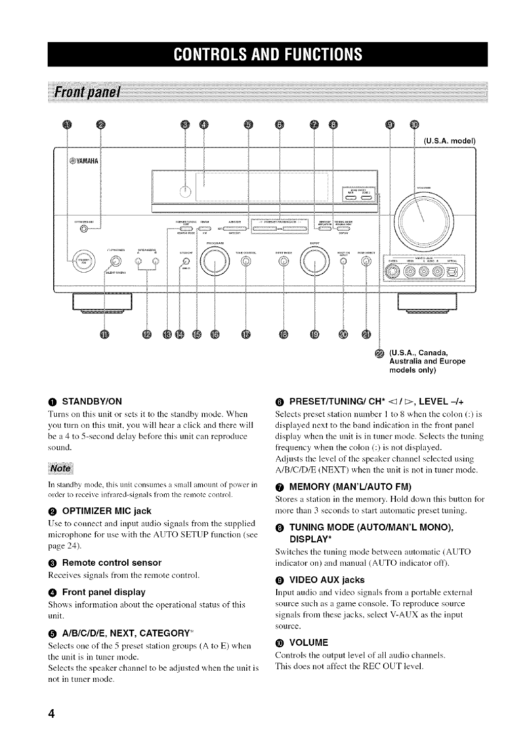
O STANDBY/ON
Turns on this unit or sets it to tile standby mode. When
you turn on this unit, you will hear a click and there will
be a 4 to 5-second delay before this unit can reproduce
sound.
Ill standby mode, this unit coi>umes a small amount of power in
order to receive infrared-signals from the remote control.
OOPTIMIZER MIC jack
Use to connect and input audio signals from the supplied
microphone for use with the AUTO SETUP fimction (see
page 24).
ORemote control sensor
Receives signals from the remote control.
• Front panel display
Sho'a,s information about tile operational status of this
unit.
0AIBIClDIE, NEXT, CATEGORY*
Selects one of the 5 preset station groups (A to E) when
the unit is in tuner mode.
Selects the speaker channel to be adjusted when the unit is
not in tuner mode.
O PRESET/TUNING/CH* <:1/_>, LEVEL -/+
Selects preset station nmnber l to 8 when the colon (:) is
displayed next to the band indication in the front panel
display when the unit is in tuner mode. Selects the tuning
frequency when the colon (:) is not displayed.
Adjusts the level of the speaker channel selected using
A/B/C/D/E (NEXT) when the unit is not in tuner mode.
OMEMORY (MAR'L/AUTO FM)
Stores a station ill tile nlemory. Hokt down this button for
more than 3 seconds to start automatic preset tuning.
OTUNING MODE (AUTO/MAN'L MONO),
DISPLAY*
S'a,itches the tuning mode bet'a, een automatic (AUTO
indicator on) and manual (AUTO indicator off).
OVIDEO AUX jacks
Input audio and video signals from a portable external
source such as a game console. To reproduce source
signals from these jacks, select V-AUX as the input
source.
@VOLUME
Controls tile output level of all audio channels.
This does not affect the REC OUT level.
4
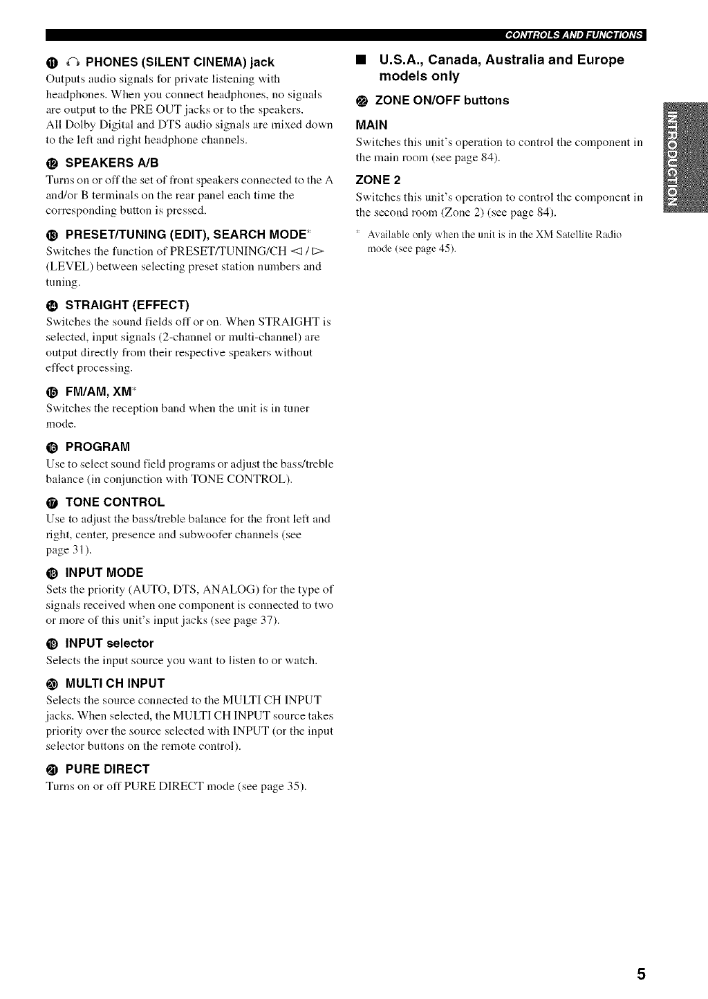
• _ PHONES (SILENT CINEMA) jack
Outputs audio signals for private listening with
headphones. When you connect headphones, no signals
are output to the PRE OUT jacks or to the speakers.
All Dolby Digital and DTS audio signals are mixed down
to the left and right headphone channels.
SPEAKERS A/B
Turns on or oft" tile set of front speakers connected to tile A
and/or B terminals on the rear panel each time the
corresponding button is pressed.
OPRESET/TUNING (EDIT), SEARCH MODE
S'a,itches tile function of PRESET/TUNING/CH <1 /C>
(LEVEL) between selecting preset station numbers and
tuning.
•STRAIGHT (EFFECT)
Sw,itches the sound fields off or on. When STRAIGHT is
selected, input signals (2-channel or multi-channel) are
output directly from their respective speakers without
effect processing.
_1 FM/AM, XM*
Svdtches the reception band "a,hen tile unit is in tuner
mode.
@PROGRAM
Use to select sound field programs or adjust tile bass!treble
balance (in conjunction with TONE CONTROL).
•TONE CONTROL
Use to adjust the bass/treble bahmce for tile front left and
right, center, presence and subwoofer channels (see
page 31 ).
_) INPUT MODE
Sets the priority (AUTO, DTS, ANALOG) for the type of
signals received when one component is connected to two
or more of this unit's input .jacks (see page 37).
@INPUT selector
Selects tile input source you want to listen to or watch.
_) MULTI CH INPUT
Selects the source connected to the MULTI CH INPUT
jacks. When selected, the MULTI CH INPUT source takes
priority over the source selected with INPUT (or the input
selector buttons on the remote control).
@PURE DIRECT
Turns on or off PURE DIRECT mode (see page 35).
,4,P]_v# lr;{e]i_'_lF__l _VeJ _i #] _v[_jf lge] Lvi --
•U.S.A., Canada, Australia and Europe
models only
_) ZONE ON/OFF buttons
MAIN
Switches tiffs unit's operation to control tile component ill
the main room (see page 84).
ZONE 2
Switches tiffs unit's operation to control tile component ill
the second room (Zone 2) (see page 84).
Available only when the unit is in the XM Satellite Radio
mode (see page 45).
5
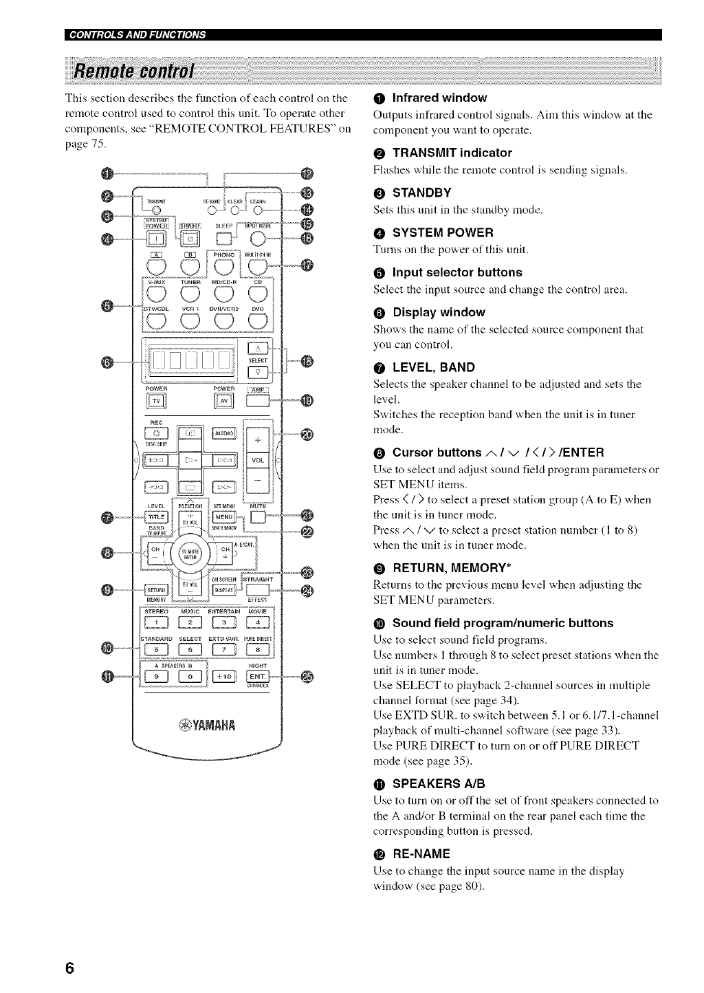
This section describes the function of each control on the
remote control used to control this unit. To operate other
components, see "REMOTE CONTROL FEATURES" on
page 75.
--
--
--
@--
............
.......
I
POWER POWER
4
.......
.........
.......
OInfrared window
Outputs infrared control signals. Aim this "_,indo'_,at tile
conlponent you "a,ant to operate.
OTRANSMIT indicator
Flashes while tile remote control is sending signals.
OSTANDBY
Sets this unit ill tile standby nlode.
OSYSTEM POWER
Turns on tile power of this unit.
OInput selector buttons
Select the input source and change the control area.
ODisplay window
Shov_'s tile name of tile selected source component that
yon call control.
OLEVEL, BAND
Selects tile speaker channel to be adjusted and sets tile
level.
Switches the reception band when the unit is in tuner
mode.
OCursor buttons/', /v/</>/ENTER
Use to select and adjust sound field program parameters or
SET MENU items.
Press { /} to select a preset station group (A to E) when
the unit is in tuner nlode.
Press ,t,, / v to select a preset station number (1 to 8)
when the unit is in tuner mode.
ORETURN, MEMORY*
Returns to the previous nlenu level when adjusting the
SET MENU parameters.
@Sound field program/numeric buttons
Use to select sound field programs.
Use nunlbers 1 through 8 to select preset stations when the
unit is in tuner mode.
Use SELECT to playback 2-channel sources in multiple
channel format (see page 34).
Use EXTD SUR. to switch between 5.1 or 6.1/7. l-channel
playback of nlulti-channel software (see page 33).
Use PURE DIRECT to turn on or off PURE DIRECT
mode (see page 35).
OSPEAKERS A/B
Use to turn on or off the set of front speakers connected to
the A and/or B terminal on the rear panel each time the
corresponding button is pressed.
•RE-NAME
Use to change the input source nanle ill tile display
window (see page 80).
6
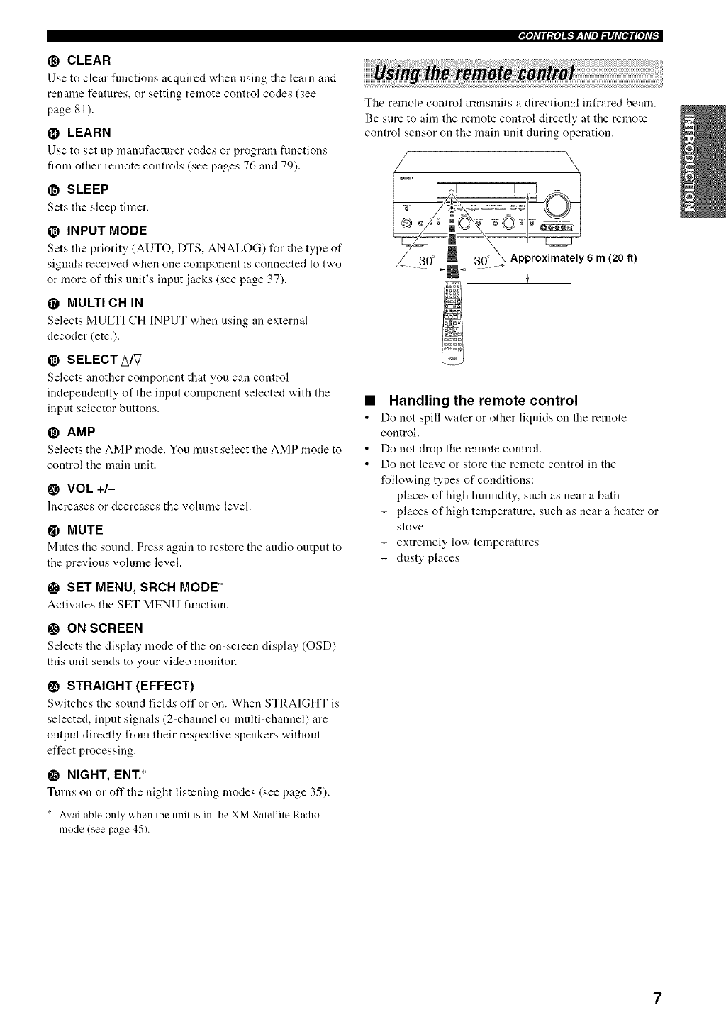
@ CLEAR
Use to clear functions acquired when using tile learn and
rename features, or setting remote control codes (see
page 81 ).
•LEARN
Use to set up manuf:tcturer codes or progr:un functions
from other remote controls (see pages 76 and 79).
@SLEEP
Sets the sleep timer.
@INPUT MODE
Sets the priority (AUTO, DTS, ANALOG) for the type of
signals received when one component is connected to two
or more of this unit's input jacks (see page 37).
•MULTI CH IN
Selects MULTI CH INPUT ,_,hen using an external
decoder (etc.).
@SELECT A/V
Selects another componeat that you can control
independently of the input component selected with the
input selector buttons.
@AMP
Selects the AMP mode. You must select the AMP mode to
control the main unit.
@VOL +/-
Increasesor decreases tile volnnae level.
@MUTE
Mutes tile sound. Press again to restore tile audio output to
the previous volume level.
SET MENU, SRCH MODE*
Activates tile SET MENU function.
ON SCREEN
Selects the display mode of the on-screen display (OSD)
this unit sends to your video monitor.
STRAIGHT (EFFECT)
S'a,itches tile sound fields off or on. When STRAIGHT is
selected, input signals (2-channel or multi-channel) are
output directly from their respective speakers without
effect processing.
ONIGHT, ENT.*
Turns on or off the night listening modes (see page 35).
' Available only when tile unit is in tile XM Satellite Radio
mode/see page 45).
,4ol;_#lglo]f,,.'lF_,l;qelgi#h'qe.'Jl[ol;_;--
The remote control transmits a directional infrared beana.
Be sure to aim the remote control directly at the remote
control sensor on the main unit during operation.
/
30 __Approximately 6 m(20 It)
+
Handling the remote control
Do not spill "_,ateror other liquids on tile remote
control.
Do not drop tile remote control.
Do not leave or store the remote control in the
following types of conditions:
places of high humidity, such as near a bath
- places of high temperature, such as near a heater or
stove
- extremely low temperatures
- dusty places
7
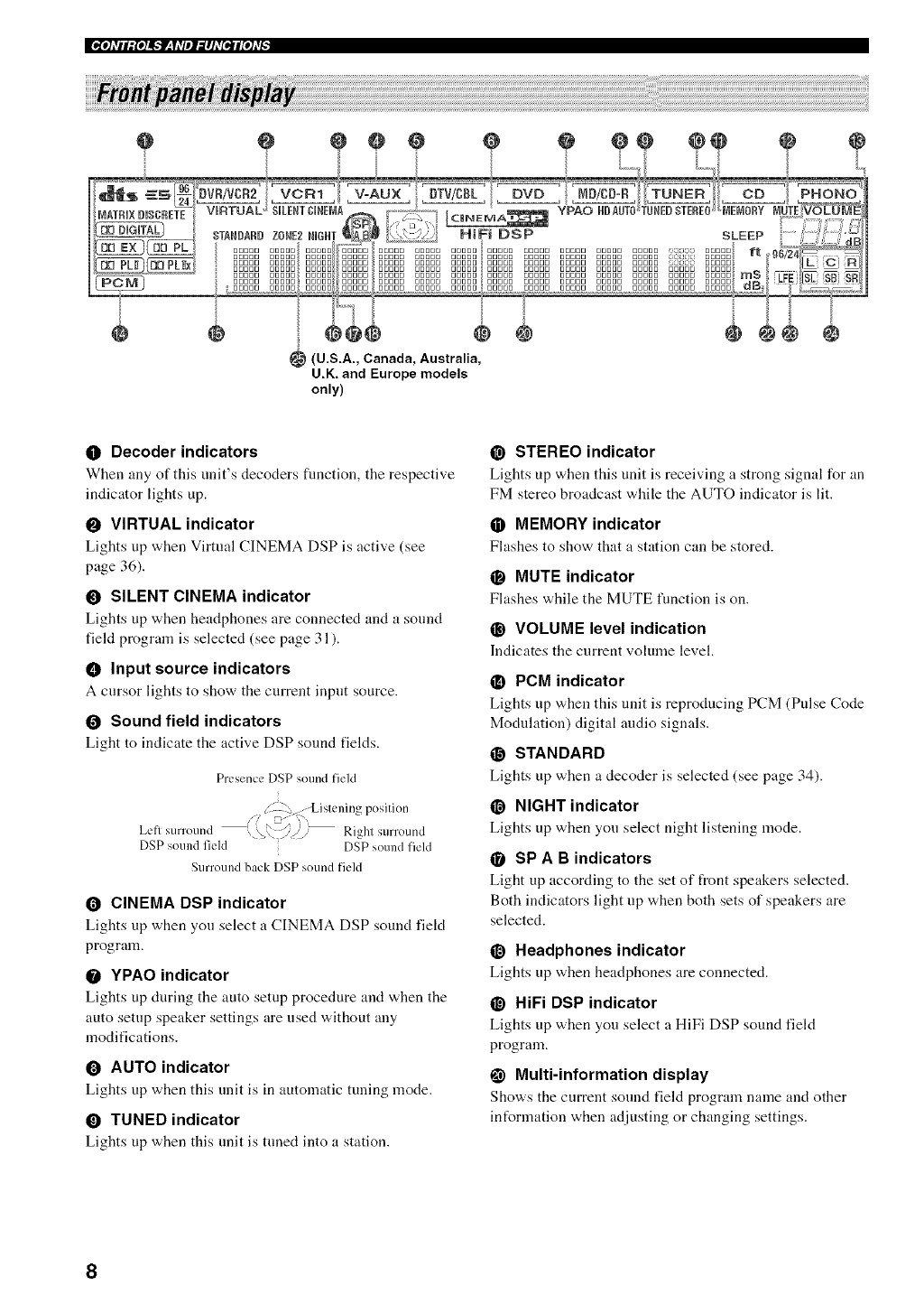
(U.S.A., Canada, Australia,
U.K. and Europe models
only)
ODecoder indicators
When any of this unit's decoders fimction, the respective
indicator lights up.
OVIRTUAL indicator
Lights up when Virtual CINEMA DSP is active (see
page 36).
OSILENT CINEMA indicator
Lights up when headphones are connected and a sound
field program is selected (see page 31).
• Input source indicators
A cursor lights to show the current input source.
OSound field indicators
Light to indicate the active DSP sound fields.
Presence DSP sound field
/.IZ .---Ls e _ _ p s n
Left surround , _,,:7/, _ Rig1 surroun_
DSP sound field DSP sound field
Surround back DSP sound field
OCINEMA DSP indicator
Lights up when you select a CINEMA DSP sound fiekt
program.
OYPAO indicator
Lights up during the auto setup procedure and when tile
auto setup speaker settings are used without any
modifications.
OAUTO indicator
Lights up when this unit is in automatic tuning mode.
OTUNED indicator
Lights up when this unit is tuned into a station.
@STEREO indicator
Lights up when this unit is receiving a strong signal for an
FM stereo broadcast w,hile tile AUTO indicator is lit.
•MEMORY indicator
Fhtshes to show that a station can be stored.
•MUTE indicator
Flashes while the MUTE function is on.
@VOLUME level indication
Indicates the current volume level.
•PCM indicator
Lights up when this unit is reproducing PCM (Pulse Code
Modulation) digital audio signals.
O STANDARD
Lights up when a decoder is selected (see page 34).
@ NIGHT indicator
Lights up when you select night listening mode.
QSP A B indicators
Light up according to the set of front speakers selected.
Both indicators light up when both sets of speakers are
selected.
@Headphones indicator
Lights up when headphones are connected.
@HiFi DSP indicator
Lights up when you select a HiFi DSP sound field
program.
Multi-information display
Shows the current sound field program name and other
int_rmation when adjusting or changing settings.
8
@SLEEP indicator
Lights up while the sleep timer is on.
96/24 indicator
Lights up when a DTS 9(,/24 signal is input to this unit.
LFE indicator
Lights up v&en tile input signal contains tile LFE signal.
Input channel indicators
Indicate tile channel components of tile current digital
input signal.
•U.S.A., Canada, Australia and Europe
model only
ZONE 2 indicator
Lights up when Zone 2 po'a, er is on.
4,Pl;_#lg[o]i_.'tF_,l;qelgi#h'qe.'jl[olg_;--
9
@
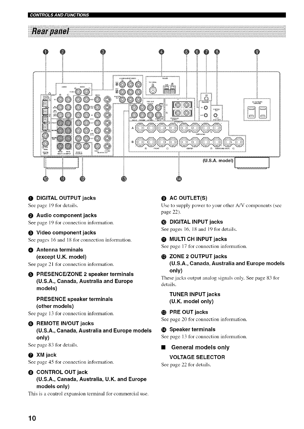
0 DIGITAL OUTPUT jacks
See page 19 for details.
OAudio component jacks
See page 19 for connection information.
OVideo component jacks
See pages 16 and 18 for connection information.
•Antenna terminals
(except U.K. model)
See page 21 t_r connection information,
OPRESENCE/ZONE 2 speaker terminals
(U.S.A., Canada, Australia and Europe
models)
PRESENCE speaker terminals
(other models)
Seepage 13 t_r connection information.
OREMOTE IN/OUT jacks
(U.S.A., Canada, Australia and Europe models
only)
See page 83 for details.
OXM jack
See page 45 t_r connection information,
O CONTROL OUT jack
(U.S.A., Canada, Australia, U.K. and Europe
models only)
This is a control expansion terminal for commercial use.
•AC OUTLET(S)
Use to supply power to your other A/V components (see
page 22).
@DIGITAL INPUT jacks
See pages 16, 18 and 19 for details.
•MULTI CH INPUT jacks
See page 17 for connection information.
OZONE 2 OUTPUT jacks
(U.S.A., Canada, Australia and Europe models
only)
These jacks output analog signals only. See page 83 for
details.
TUNER INPUT jacks
(U.K. model only)
@PRE OUT jacks
See page 20 for connection information.
•Speaker terminals
See page 13 for connection information.
•General models only
VOLTAGE SELECTOR
See page 22 for details.
10
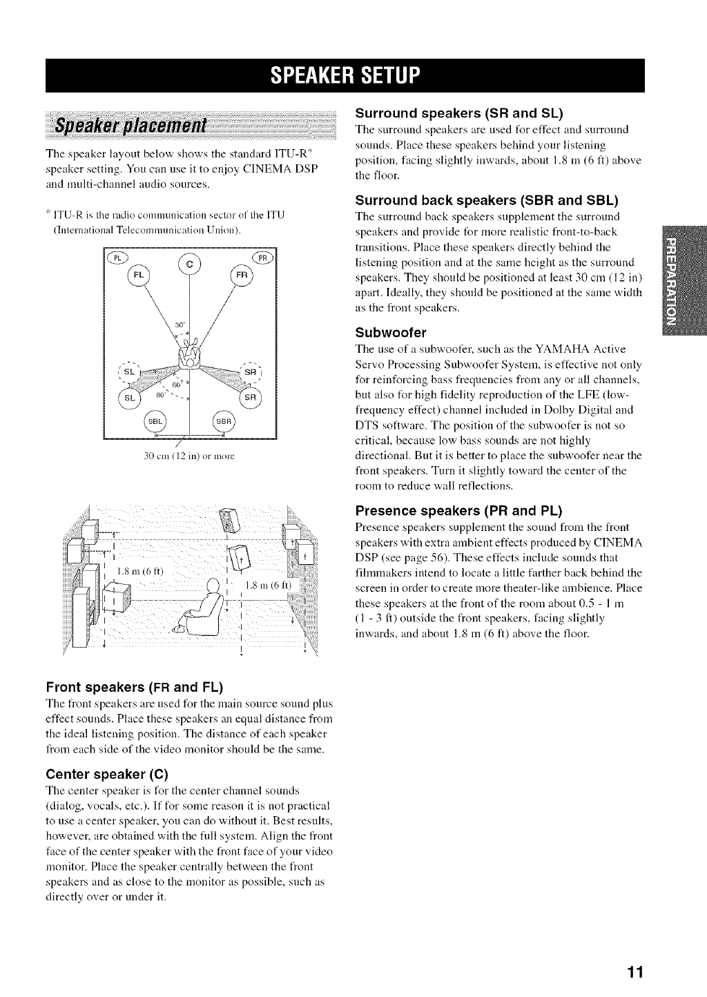
The speaker layout below shows the standard ITU-R*
speaker setting. You can use it to enjoy CINEMA DSP
and multi-channel audio sources.
:_ITU_R is Ihe radio communication seclor of Ihe ITU
(Inlernational Telecomnmnication Union).
/
30 Clil(12 in) or more
Surround speakers (SR and SL)
The surround speakers are used for effect and surround
sounds. Place these speakers behind your listening
position, facing slightly inwards, abont 1.8 in (6 tl) above
the floor.
Surround back speakers (SBR and SBL)
The surround back speakers snpplement the surround
speakers and provide for more realistic front-to-back
transitions. Place these speakers directly behind the
listening position and at the same height as the surround
speakers. They should be positioned at least 30 cm (12 in)
apart. Ideally, they shonld be positioned at the same width
as the front speakers.
Subwoofer
The use ofa subwoofer, such as the YAMAHA Active
Servo Processing Subwoofer System, is effective not only
for reinforcing bass frequencies from any or all channels,
but also t_r high fidelity reproduction of the LFE (low-
frequency effect) channel included in Dolby Digital and
DTS software. The position of the subwoofer is not so
critical, because low bass sounds are not highly
directional. But it is better to place the subwoofer near the
front speakers. Turn it slightly toward the center of the
room to reduce wall reflections.
Presence speakers (PR and PL)
Presence speakers supplement the sound from the front
speakers with extra ambient effects produced by CINEMA
DSP (see page 56). These effects include sonnds that
filmnmkers intend to locate a little farther back behind the
screen in order to create more theater-like ambience. Place
these speakers at the front of the room about 0.5 - 1 m
(1 - 3 ft) outside the front speakers, facing slightly
inwards, and about 1.8 m (6 ft) above the floor.
Front speakers (FR and FL)
The t¥ont speakers are used for the main source sound plus
effect sounds. Place these speakers an equal distance from
the ideal listening position. The distance of each speaker
from each side of the video monitor should be the same.
Center speaker (C)
The center speaker is for the center channel sounds
(dialog, vocals, etc.). If for some reason it is not practical
to use a center speaker, you can do without it. Best results,
however, are obtained with the fldl system. Align the front
face of the center speaker with the front face of your video
monitor. Place the speaker centrally between the front
speakers and as close to the monitor as possible, such as
directly over or under it.
11
IFl+i_t+f-+,+f'l-.-il_I"
Be sure to connect the left channel (L), right channel (R),
"+" (red) and "-" (black) properly. If the connections are
faulty, no sound will be heard from the speakers, and if the
polarity of the speaker connections is incorrect, the sound
will he unnatural and lack bass.
[_allJl[OJAV,
•If you will use 4 or 6 ohm speakers, be sure to
set this unit's speaker impedance setting to 4
ohms before using (see page 23).
• Before connecting tile speakers, make sure that the
power of this unit is off.
• Do not let the bare speaker wires touch each other or do
not let them touch any metal part of this unit. This
could damage this unit and/or speakers.
• Use magnetically shielded speakers. If this type of
speakers still creates the interference with the monitor,
place the speakers away from the monitor.
A speaker cord is actnally a pair of insulated cables
rnnning side by side. One cable is colored or shaped
differently, perhaps with a stripe, groove or ridges.
Connect the striped (grooved, etc.) cable to the "+" (red)
terminals on this unit and your speaker. Connect the plain
cable to the "-" (black) terminals.
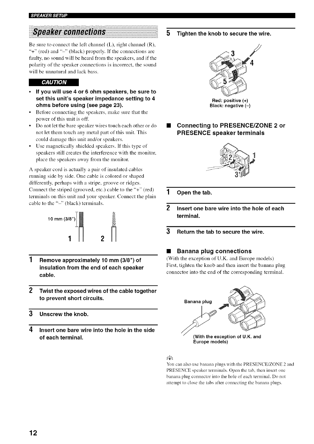
10 mm (3/I ) 2
1 Remove approximately 10 mm (3/8") of
insulation from the end of each speaker
cable.
2Twist the exposed wires of the cable together
to prevent short circuits.
3 Unscrew the knob.
4Insert one bare wire into the hole in the side
of each terminal.
5 Tighten the knob to secure the wire.
Red: positive (+)
Black: negative (-)
•Connecting to PRESENCE/ZONE 2 or
PRESENCE speaker terminals
1 Open the tab.
2Insert one bare wire into the hole of each
terminal.
3 Return the tab to secure the wire.
•Banana plug connections
(With the exception of U.K. and Europe models)
First, tighten the knob and then insert the banana plug
connector into the end of the corresponding terminal.
Banana plug
(With the exception of U.K. and
Europe models)
Youcan also use banana plugs with the PRESENCE/ZONE 2 and
PRESENCE speaker terminals. Open the tab. then insert one
banana plugconnector intu the hole of each termiuah Du not
attempt to close the tabs after cunnecting the banana plugs.
12
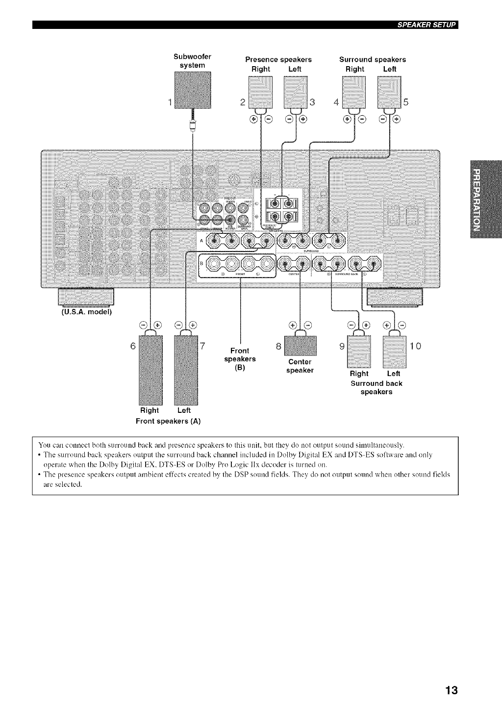
Subwoofer
system Presence speakers
Right Left
23
Surround speakers
Right Left
(U.S.A. model)
®
Right Left
Front speakers (A)
7 8 9 10
Front
speakers Center
(B) speaker Right Left
Surround back
speakers
You can connect both surround back and presence speakers to this unit. but they do not output sound simultaneously.
• The surround back speakers output the surround back channel included in Dolby Digital EX and DTS-ES software and only
operate when the Dolby Digital EX. DTS-ES or Dolby Pro Logic llx decoder is turned on.
• The presence speakers output ambient effects created by the DSP sound fields. They do not output sound when other sound fields
are selected.
13
IFI+I_T+<-+,+f'l-.-il_I"
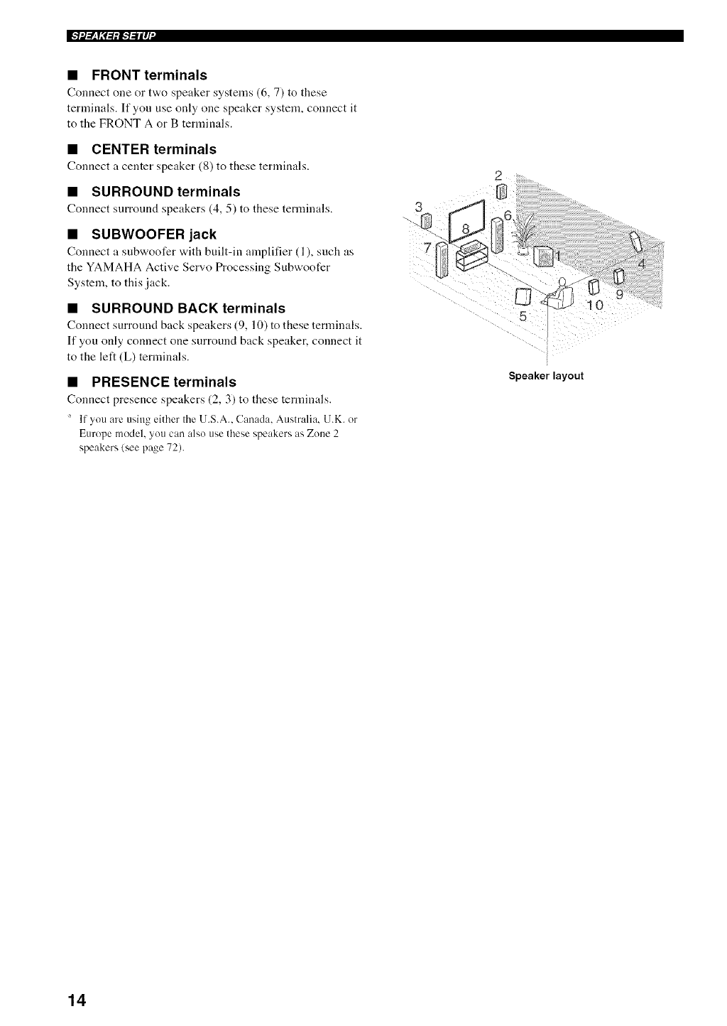
•FRONT terminals
Connect one or tv,,o speaker systems (6, 7) to these
terminals. If you use only one speaker system, connect it
to the FRONT A or B terminals.
•CENTER terminals
Connect a center speaker (8) to these ternlinals.
•SURROUND terminals
Connect surround speakers (4, 5) to these terminals.
•SUBWOOFER jack
Connect a subwoofer "a,ith built-in amplifier (1), such as
the YAMAHA Active Servo Processing Subwoofer
System, to this jack.
•SURROUND BACK terminals
Connect surround back speakers (9, 10) to these terminals.
If you only connect one surround back speaker, connect it
to the left (L) terminals.
•PRESENCE terminals
Connect presence speakers (2, 3) to these terminals.
' If you are using either the U.S.A.. Canada. Australia. U.K. or
Europe model, you can also use these speakers as Zone 2
speakers/see page 72).
3
Speaker layout
10
14
f_.q IM_olAvj
Do not connect this unit or other components to the mains
power until all connections between components are
complete.
•Cable indications
For analog signals
left analog cables CLL£
right analog cables 0_>
For digital signals
optical cables _'(oD
coaxial cables ,'/I:c L'-'
For video signals
video cables ,,,,,,,,,,,,,,,,,,,__ _,
S-video cables _4/g _
component video cables
•Analog jacks
You can input analog signals from audio components by
connecting audio pin cable to the analog jacks on this unit.
Connect red plugs to the right jacks and white plugs to the
left jacks.
•Digital jacks
This unit has digital jacks for direct transmission of digital
signals throngh either coaxial or fiber optic cables. You
can use the digital jacks to input PCM, Dolby Digital and
DTS bitstreams. When you connect components to both
the COAXIAL and OPTICAL jacks, priority is given to
the input signals from the COAXIAL jack. All digital
input jacks are compatible with 96-kHz sampling digital
signals.
Note
This unit handles digital and analog signals independently. Thus
audio signals input to the analog jacks are only output to the
analug OUT/REC) jacks. Likewise audio signals input to the
digital (Ot_ICAL or COAXIAL)jacks are only output to the
DIGITAL OUTPUT jack.
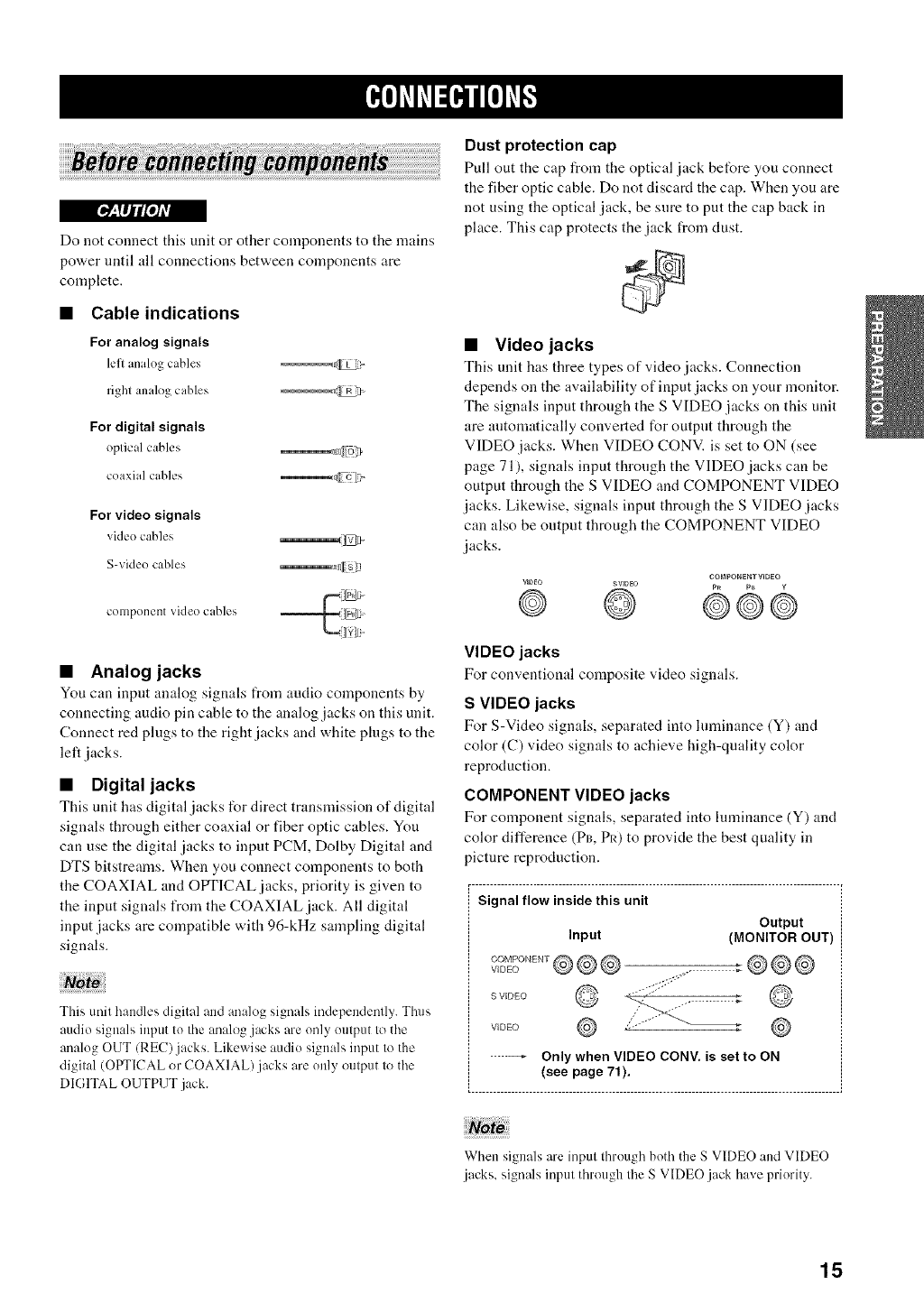
Dust protection cap
Pull out the cap from the optical jack before you connect
the fiber optic cable. Do not discard the cap. When you are
not using the optical jack, be snre to put the cap back in
place. This cap protects the jack from dust.
•Video jacks
This unit has three types of video jacks. Connection
depends on the availability of input jacks on your monitor.
The signals input through the S VIDEO jacks on this unit
are antomatically converted for outpnt through the
VIDEO jacks. When VIDEO CONV. is set to ON (see
page 71), signals input throngh the VIDEO jacks can be
output through the S VIDEO and COMPONENT VIDEO
jacks. Likewise, signals input throngh the S VIDEO jacks
can also be output through the COMPONENT VIDEO
jacks.
co_._ PONENT VIDEO
VIDEO SVlDBO p_ p_ ¥
@ @ @©e
VIDEO jacks
For conventional composite video signals.
S VIDEO jacks
For S-Video signals, separated into luminance (Y) and
color (C) video signals to achieve high-quality color
reproduction.
COMPONENT VIDEO jacks
For component signals, separated into hnninance (Y) and
color difference (Pro Pk) to provide the best quality in
picture reproduction.
r- ..................................................................................................... ,
Signal flow inside this unit
Output
Input (MONITOR OUT)
......o-.
S VIDEO
VIDE() .-
When signals are input through both the S VIDEO and VIDEO
.jacks, signals input through the S VIDEO.jack have priority.
15
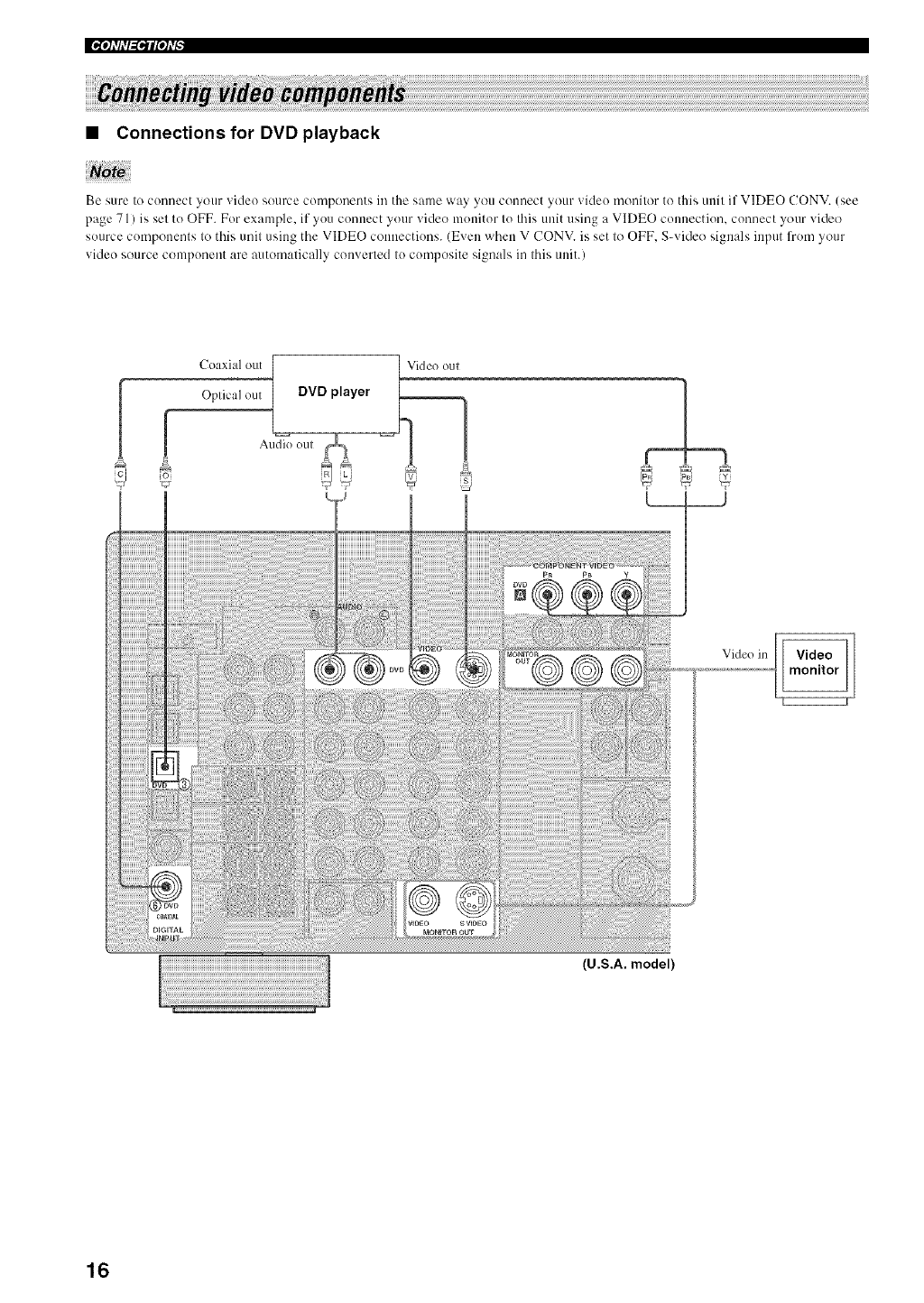
•Connections for DVD playback
Be sure to connect your video source components in the same way you connect your video monitor to this unit if VIDEO CONV. (see
page 71 ) is set to OFF. For example, if you connect your video monitor to this trait using a VIDEO connection, connect your video
source components to this unit using the VIDEO connections. (Even when V CONV. is set to OFF. S-video signals input from your
video source component are automatically converted to composite signals in this unit.)
Coaxial out
.! i Opticalom DVDplayer _=_
Au(lk) oul
7i J
(U.S.A. model)
16
_qflfN'_lfqfi--
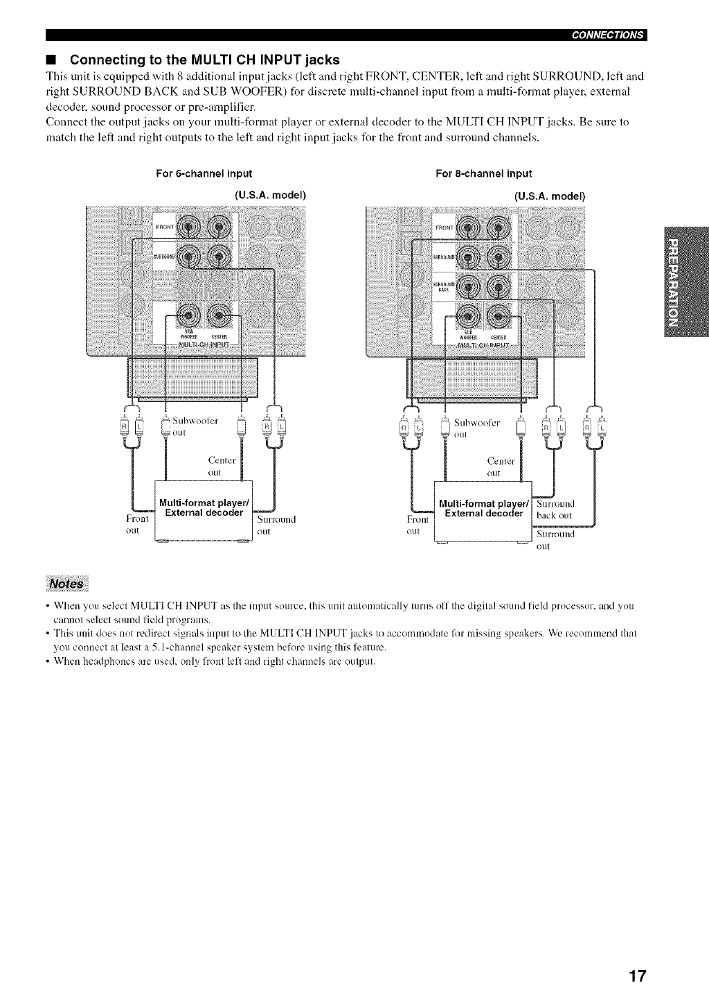
• Connecting to the MULTI CH INPUT jacks
This unit is equipped with 8 additional iuput jacks (left and right FRONT, CENTER, left and right SURROUND, left and
right SURROUND BACK and SUB WOOFER) for discrete multi-channel input from a nmlti-format player, external
decoder, sound processor or pre-amplifier.
Connect the output jacks on your multi-format player or external decoder to the MULTI CH INPUT jacks. Be sure to
match the left and right outputs to the left and right input jacks for the front and surround channels.
For 6-channel input
(U.S.A. model)
For 8-channel input
(U.S.A. model)
_@.... oul_Subwooler..... __ __ _":
!o,I L!
Multi-format player/
External decoder l====_
[ S,,!'ro,,.d
o,. [ jo,.
Front
OU[
Subwoofer / f- [f_/ /L]
!out k l [
Multi-format player/I Smro=md
External decoder [ lx_k out
_/irro/llld
OLI[
•When you select MULTI CH INPUT as the input source, this unit automatically turns off the digital sound field processor, and you
cannot select sound l'ield programs.
• This unit does not redirect signals input to the MULTI CH INPUT j_cks to accommodate for missing speakers. We recommend that
you connect at least a 5.l-channel speaker system bel-ore using this feature.
• When headphones are used. only front left and right channels are output.
17
|_iql'M_'llPll'_
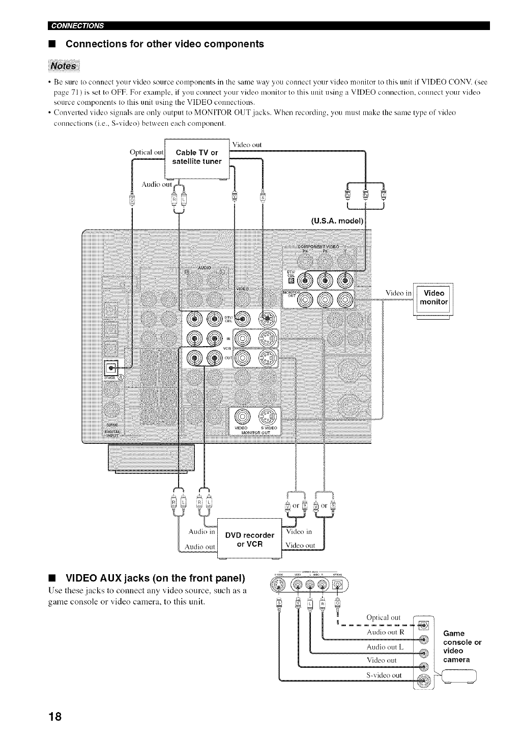
•Connections for other video components
Nbte ;
• Be sure to connect your video source componeuts in tile same way you cuunect your video munitor to this unit if VIDEO CONV. (see
page 71 ) is set tu OFF. Fur example, if yuu connect your video monitur tu this unit using a VIDEO connuctiun, connect your video
source components to this unit using the VIDEO connections.
• Converted video signals are only output to MONITOR OUT jacks. When recording, you must make the same type of video
connections (i.e.. S-videu) between each component.
Optical oul Cable TV or
,satellite tuner
Audio oul
Video in
DVD recorder
or VCR
•VIDEO AUX jacks (on the front panel)
Use these jacks to connect any video source, such as a
game console or video camera, to this unit.
j Vid_ out J
I= = = =Op==tic_d_)u/==_
Audio out R =_ Game
_:# console or
Au(ho out L @ I video
Video oul 2] camera
S-vkleo OUt __
18
_qflfN'_lfqfi--
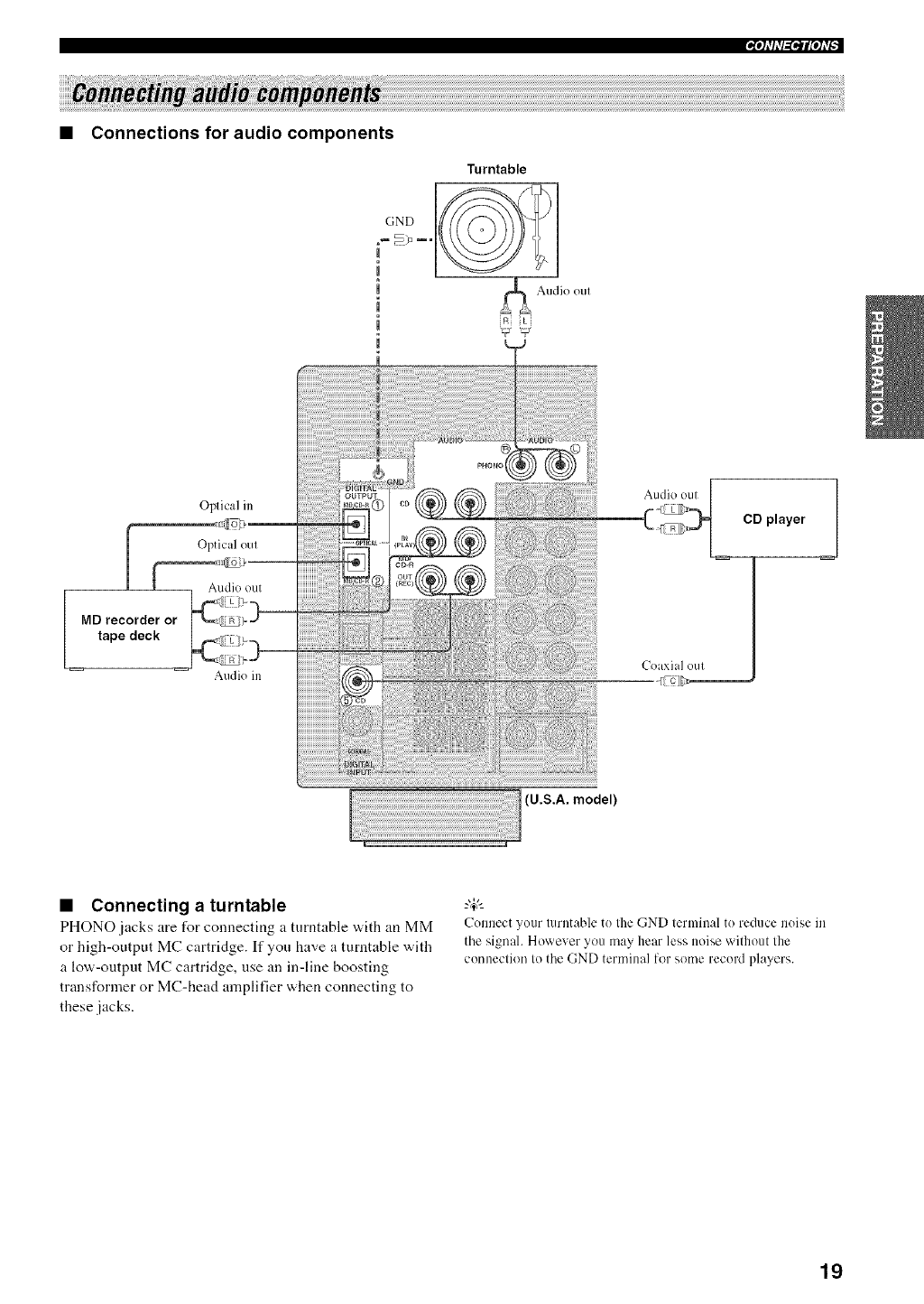
• Connections for audio components
Oplical in
I Optical oul
MD recorder or
tape deck
Audio in Coaxial ()Ul
CD player
iiiiiiii_i_iiiiiiiiiiiiii!ii!ii!ii!ii!ii!ii!ii!ii!ii!ii!ii!ii!ii!ii!ii!ii!ii!ii!ii!ii!ii!ii!ii!ii!ii!ii!ii!ii!ii!ii!ii!ii!ii!ii!ii!ii!ii!ii!ii!ii!ii!ii!ii!ii!ii!ii!ii!ii!ii!ii!ii!ii!ii!ii!ii!ii!ii!ii!ii!ii!ii!ii!ii!ii!ii!ii!ii!ii!ii!ii!ii!ii!ii!ii!ii!ii!ii!ii!ii!ii!ii!ii!ii!ii!iiiiiiii_i_iiiiiiii_iiii_!i_iii_!_i!i!I0...sAmode,,
•Connecting a turntable
PHONO jacks are for connecting a tun]table w,ith an MM
or high-output MC cartridge. If you have a turntable with
a low-output MC cartridge, use an in-line boosting
transformer or MC-head amplifier when connecting to
these jacks.
Connect your turntable to the GND terminal to reduce noise in
the signah However you may hear less noise without the
connection to the GND terminal for some record players.
19
•Connecting to an external amplifier
If you "a,ant to increase the power outpnt to the speakers,
or want to use another amplifier, connect an external
amplifier to the PRE OUT jacks as follows.
• When audio pin plugs are connected to the PRE OUT jacks for
output to an external amplifier, do not make connections to the
corresponding SPEAKERS terminals. Set the volume of the
amplifier connected to this unit to the maximum.
• The signals output through the FRONT PRE OUT and
(-?ENTER PRE OUT jacks are affected by the TONE
CONTROL settings.
• If SPEAKERS A is turned off and SP B is set to ZONE B (see
page 72), signals will only be output from the FRONT PRE
OUT jacks.
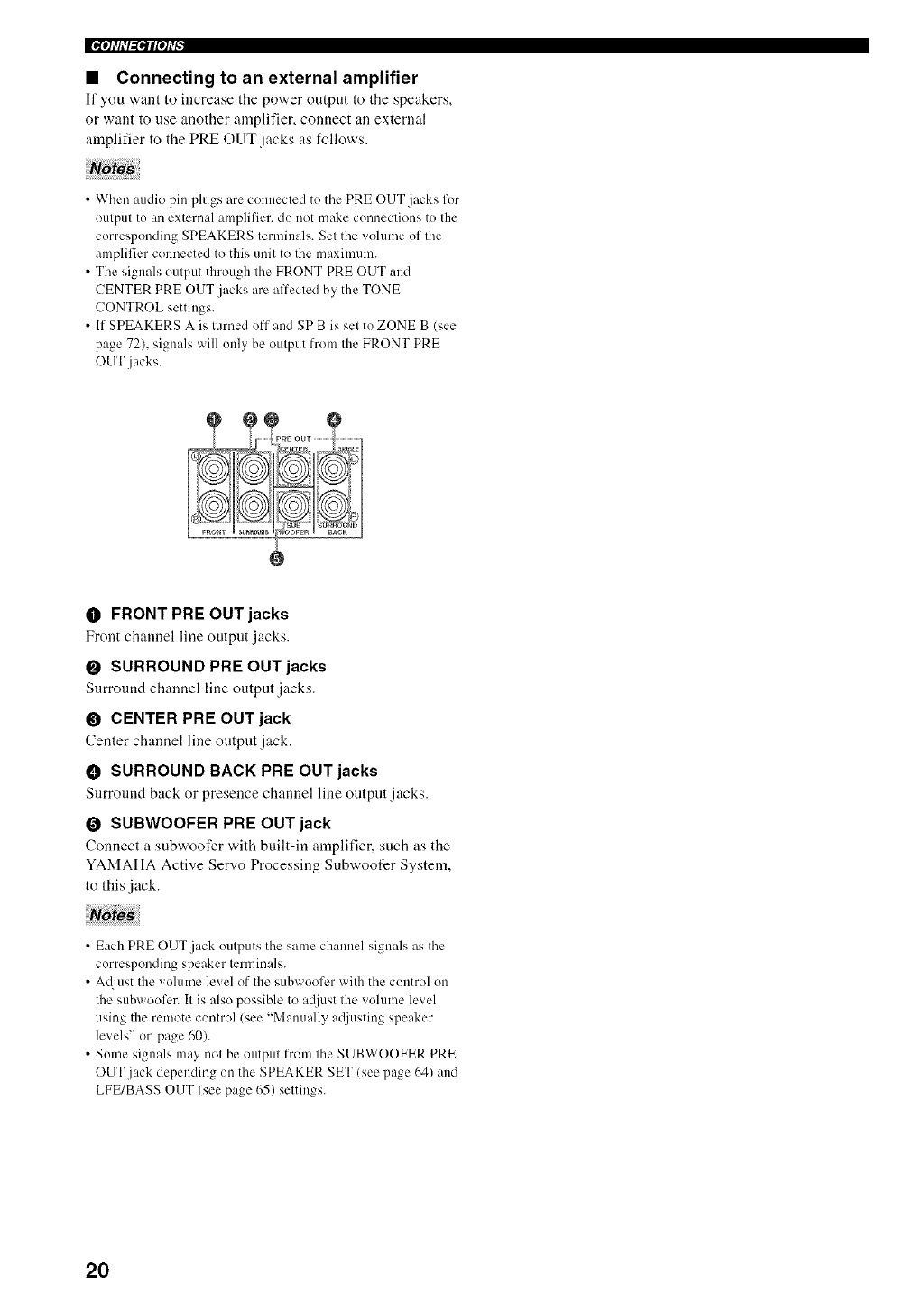
OFRONT PRE OUT jacks
Front channel line output jacks.
OSURROUND PRE OUT jacks
Surround channel line output jacks.
OCENTER PRE OUT jack
Center channel line output jack.
• SURROUND BACK PRE OUT jacks
Surround back or presence channel line output jacks.
OSUBWOOFER PRE OUT jack
Connect a subwoofer "a,ith built-in amplifier, such as the
YAMAHA Active Servo Processing Subwoofer System,
to this jack.
• Each PRE OUT jack outputs the same channel signals as the
corresponding speaker terminals.
• Atljust the volume level of the subwoofcr with the control on
the subwoufer. It is also possible to atliust the volume level
using the remote control (see "Malmally a_ljustiog speaker
levels" on page 60).
• Some signals may not be output from the SUBWOOFER PRE
OUT.jack depending uu the SPEAKER SET/see p_ge 64) and
LFE/BASS OUT (see page 65) settings.
20
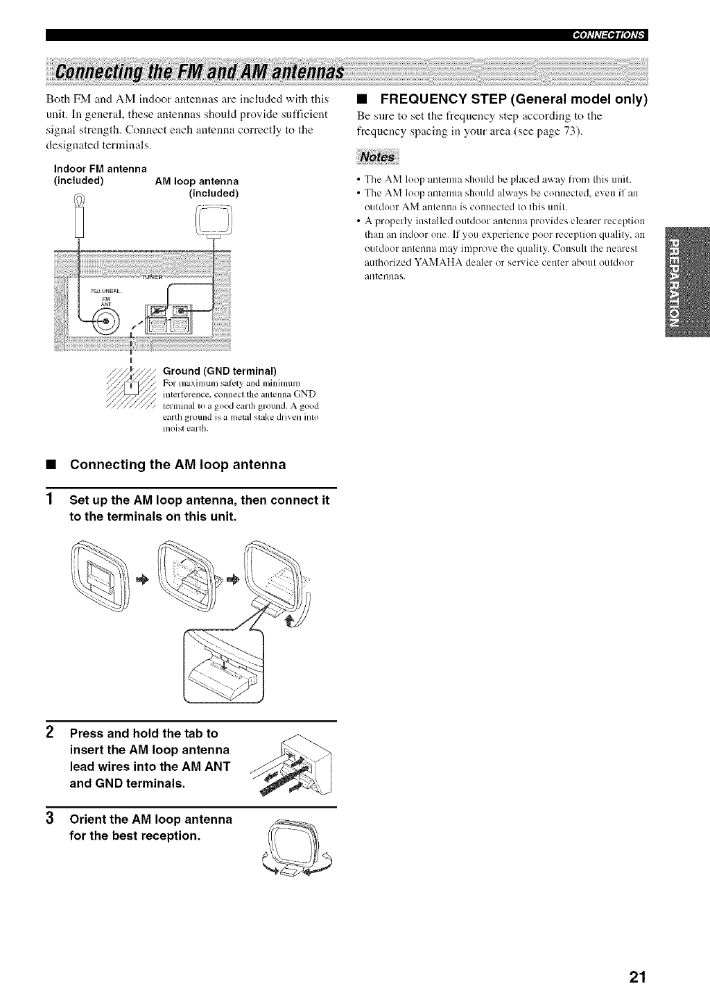
Both FM and AM indoor antennas are included with this
unit. In general, these antennas should provide sufficient
signal strength. Connect each antenna correctly to the
designated terminals.
Indoor FM antenna
(included) AM loop antenna
(included)
•FREQUENCY STEP (General model only)
Be sure to set the frequency step according to the
frequency spacing in your area (see page 73).
• Tile AM loop antenna should be placed away from this unit.
• The AM loop antenna should always be connected, even if an
outdoor AM antenna is connected to this unit.
• A properly installed outdoor antenna provides clearer reception
than an indoor one. If you experience poor reception quality, an
outdoor antenna may improve the quality. Consult the nearest
authorized YAMAHA dealer or service center about outdoor
antennas.
1
Ground (GND terminal)
For maximum s_,ti_ly m_d minimum
interli:rence, connect the antenna GND
terminal to a good earth ground. A good
earth ground is a metal slake driven into
moist earth.
Connecting the AM loop antenna
Set up the AM loop antenna, then connect it
to the terminals on this unit.
.%.%
Press and hold the tab to
insert the AM loop antenna
lead wires into the AM ANT
and GND terminals.
Orient the AM loop antenna
for the best reception.
21
• Connecting the AC power cord
Plug tile power cord into an AC wall outlet.
•AC OUTLET(S) (SWITCHED)
U.K. and Australia models ................................... 1 outlet
Korea model .............................................................. None
Other models ........................................................ 2 outlets
Use these outlets to connect the power cords from your
other components to this unit. Power to the AC
OUTLET(S) is controlled by this unit's STANDBY/ON
(or SYSTEM POWER and STANDBY). The outlet(s)
supply power to any connected component whenever this
unit is turned on. For information on the maximum power
(total power consumption of components), see
"SPECIFICATIONS" on page 102.
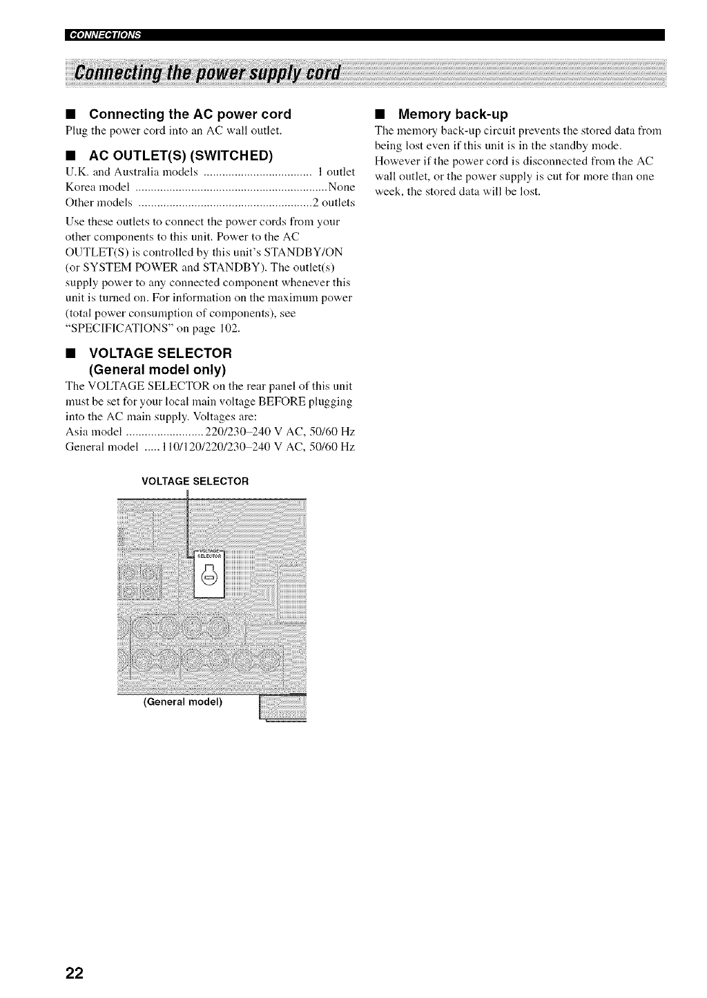
•VOLTAGE SELECTOR
(General model only)
Tile VOLTAGE SELECTOR on tile rear panel of this unit
must be set for your local main voltage BEFORE plugging
into the AC main supply. Voltages are:
Asia model ......................... 220/230)-40 V AC, 50/60 Hz
General model ..... 110/120/220/230 240 V AC, 50/60 Hz
VOLTAGE SELECTOR
•Memory back-up
Tile memory back-up circuit prevents the stored data from
being lost even if this unit is in the standby mode.
However if the power cord is disconnected from the AC
wall outlet, or the power supply is cut for more than one
week, the stored data will be lost.
(General model)
22
_qflfN'_lfqfi--
[_:llllEolAvl
If you are using 4 or 6 ohm speakers, set the impedance to
4 or 6 ohms as follows before turning on the power.
Be sure this unit is in the standby mode.
Turn off the power to this unit, and while
holding down STRAIGHT (EFFECT), press
STANDBY/ON.
This unit turns on, and "SP IMP."appears in the front
panel display.
STRAIGHT
While holding
down, press
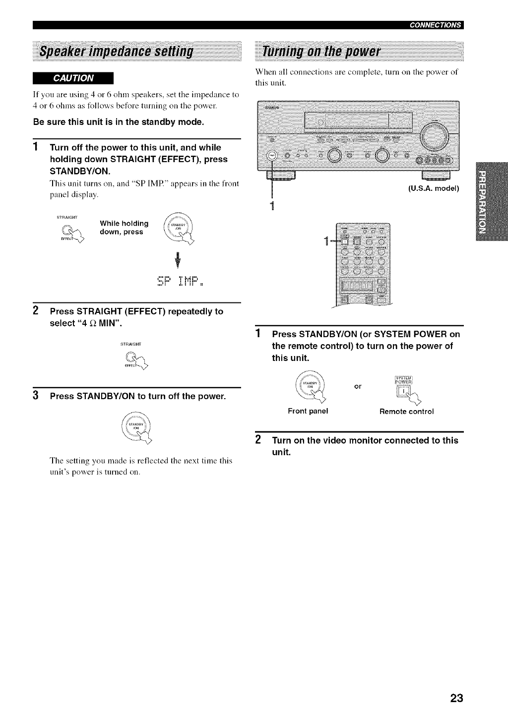
When all connections are complete, turn on the power of
this unit.
(U.S.A. model)
lm
t"' i"l T l...[ i"l
.... • i .i. _ _i II
Press STRAIGHT (EFFECT) repeatedly to
select "4 _-_MIN".
3 Press STANDBY/ON to turn off the power.
The setting you made is reflected the next time this
unit's power is turned on.
Press STANDBY/ON (or SYSTEM POWER on
the remote control) to turn on the power of
this unit.
F_7_Tg_
[PowsRj
or
Front panel Remote control
Turn on the video monitor connected to this
unit.
23
This receiver employs YAMAHA Parametric Room
Acoustic Optimizer (YPAO) technology which lets you
avoid troublesome listening-based speaker setup and
achieves highly accurate sound adjustments. The supplied
optimizer microphone collects and analyzes the sound
your speakers produce in your actual listening
environnlent.
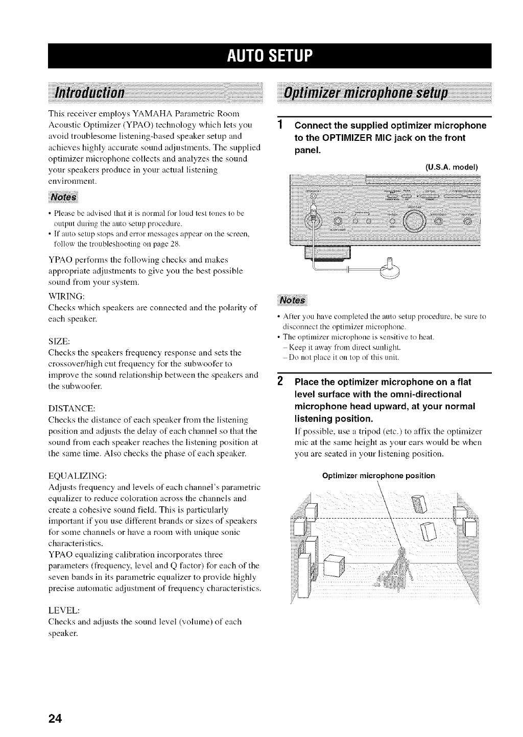
Connect the supplied optimizer microphone
to the OPTIMIZER MIC jack on the front
panel.
(U.S.A. model)
•Please be advised that it is normal for loud test tones to be
output during the auto setup procedure.
• If auto setup stops and error messages appear onthe screen.
follow the troubleshooting oll page 28.
YPAO performs the following checks and makes
appropriate adjustments to give you the best possible
sound from your system.
WIRING:
Checks which speakers are connected and the polarity of
each speaker.
SIZE:
Checks the speakers frequency response and sets the
crossover/high cut frequency for the subwoofer to
improve the sound relationship between the speakers and
the subwoofer.
DISTANCE:
Checks the distance of each speaker from the listening
position and adjusts the delay of each channel so that the
sound from each speaker reaches the listening position at
the same time. Also checks the phase of each speaker.
EQUALIZING:
Adjusts frequency and levels of each channel's parametric
equalizer to reduce coloration across the channels and
create a cohesive sound field. This is particularly
important if you use different brands or sizes of speakers
t_r some channels or have a room with unique sonic
characteristics.
YPAO equalizing calibration incorporates three
parameters (frequency, level and Q factor) for each of the
seven bands in its parametric equalizer to provide highly
precise automatic adjustment of t_eqnency characteristics.
LEVEL:
Checks and adjusts the sound level (volume) of each
speaker.
• After you have completed the auto setup procedure, be sure to
disconnect the optimizer microphone.
• The optimizer microphone is sensitive to heat.
Keepit away from direct sunlight.
Do not place it on top of this unit.
Place the optimizer microphone on a flat
level surface with the omni-directional
microphone head upward, at your normal
listening position.
If possible, use a tripod (etc.) to affix the optimizer
mic at the same height as your ears would be when
you are seated in your listening position.
Optimizer microphone position
24
i|ll[oJN=/Iq'l
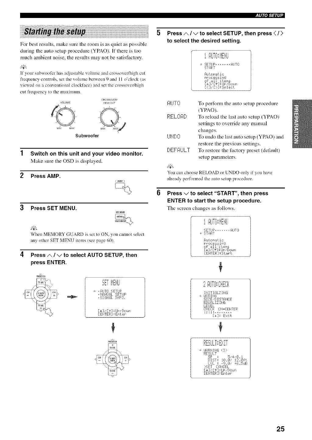
For best results, make sure the room is as quiet as possible
during the auto setup procedure (YPAO). If there is too
much ambient noise, the results may not be satisfactory.
W--
if your subwoo%r has a([iustable volume and crossovedhigh cut
frequency controls, set the volume between 9 and 11 ()'clock (as
viewed on a conventional clockface) and set the crossovedhigh
cut frequency to the maximum.
VOLUME
, E z
©
M_N MAX
Subwoofer
OROSSOVE£/
HIQH OUT
Switch on this unit and your video monitor.
Make sure the OSD is displayed.
Press AMP.
! AMP /
Press SET MENU.
sll MEIU
W--
WhenMEMORY GUARD is set to ON. you cannot select
any other SET MENU items (see page 60).
Press/x /vto select AUTO SETUP, then
press ENTER.
A
:;ET)E4'J-,
, A!JT[I :,_.,L,'-:'r":,
, i,IlqiI_IFL SE]LIF'
,S{GiIAL IiiFO,
[m] [T]SLIF Do£q-i
[ Ei4TER ] _E:I_!er
/,
Press/,, /vto select SETUP, then press </>
to select the desired setting.
i HUUJqiCi'iU
÷ 5E:TLIF', ...... RLITO
STRRT
gl.Ac,_,iati c
Fr ce:_:;_irr_l
c4 +_!! items
[11' IT] ;LIF Do_,lrl
[<]'[:]:Select
r'1,...,")iH"f",i,..., To perform the auto setup procedure
(YPAO).
i:::,m,".")r., To reload the last auto setup (YPAO)
settings to override any manual
changes.
,...,iii..H".,,",_....,..., To undo the last auto setup (YPAO) and
restore the previous settings.
_...._..._r"i::ri:::r'i_...,...,_._iiT_ To restore the factory preset (default)
setup parameters.
W--
Youcan choose RELOAD or UNDO only if you ha',e
already performed Ihe aulo setup procedure.
Press vto select "START", then press
ENTER to start the setup procedure.
The screen changes as follows.
i OiiTfi_i,i_i,iii
,_ H'#:'#"H_rH'_'
'SEiTUF :,.......... i:]UT[]
-+ --, ! HK !
_ r. ,=.= = i r,q
[_] [T] _ UP"C'our!
[ENTER] _ St _!'t.
,=_ FII I?FI_ F,I iD=,b '
,,: UJU°,,LP_bi,
IHIT!FILZ ING
UIRING
EiZE/D ISTI:IHCE
EOLIIqLIZ l HG
LEUEL
CHECK CH=C ENTER
!!lli ........
Ill Exit
F_F=:=IiT_ FU?T
RI:&ILi=D"="i
ilARIIIIIG ,Z_
RESULT
SF' : 5'4 iL, !
Di:-;'r; !El,,_l !Sh,€l_:{
LUL - '.--_.El 46,, 5dB
: ':.FT CFiE:E]_
[v] : LIF Dc,_,m
..... c- c !,[L, ITL,,] ,_, .:,_
25
II_IqI",I-'I-,'iI l,I"
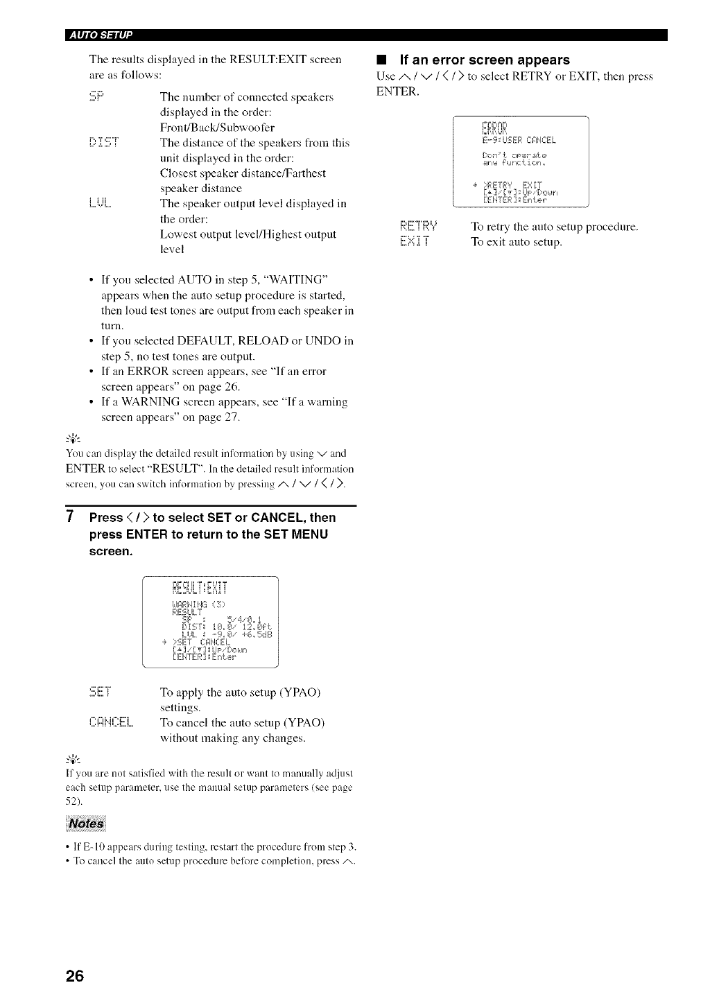
The results displayed in the RESULT:EXIT screen
are as follows:
,='i::,
r'., T,:7 "i"
1...' .I....+++
i iii
i....+...'i....
The number of connected speakers
displayed in the order:
Front/Back/Subwoofer
The distance of the speakers from this
unit displayed in the order:
Closest speaker distance/Farthest
speaker distance
The speaker output level displayed in
the order:
Lowest output level/Highest output
level
• If you selected AUTO in step 5, "WAITING"
appears when the auto setup procedure is started,
then loud test tones are output from each speaker in
turn.
• If yon selected DEFAULT, RELOAD or UNDO in
step 5, no test tones are output.
• If an ERROR screen appears, see "If an error
screen appears" on page 26.
• If a WARNING screen appears, see "If a warning
screen appears" on page 27.
"4+"-
Youcan display the detailed result information by using v and
ENTER to select "RESULT". In the detailed result information
screen, you can switch information by pressing i /V/(/>.
7Press </>to select SET or CANCEL, then
press ENTER to return to the SET MENU
screen.
•If an error screen appears
Use i /V/(/> to select RETRY or EXIT, then press
ENTER.
i::H::2Ti=,LJ
i'.<i.., i 1'.. +
i:::=..._T"i"
E.-9; LISER C:MiEEi.
[)o_1:' _1 oPeFP;f+e
_ty:l {:1 lhC _. i 0_I.
÷ :RETRY E:_:I'T
Fm] [T] !_l_aDzk n
[ EHTEF,:] _E_"li:et "¸
To retry the auto setup procedure.
To exit auto setup.
kI_]RN! NG <3)
RESULT
SF' + 5/4/+3,, 1
DiSr+ !g,,g !2,,Ch_t
LUL -% +3' +_.,, 5dB
•_ >SET C:F,HCEL
Eli 7[*] Lh: '[,c,_.J_+
[EHTEF ] sEh!:e_
:!!!;E"[ To apply the auto setup (YPAO)
settings.
P,",i..i,=.i:::'i To cancel the auto setup (YPAO)
without making any changes.
"4+'--
Ifyou are not satisfied with the result or want to manually adjust
each setup parameter, use the mauua]setup paramelers/see page
52).
• If E-10 appears during testing, restart the procedure from step 3.
• To cancel the aulo setup procedure before completion, press i.
26
1
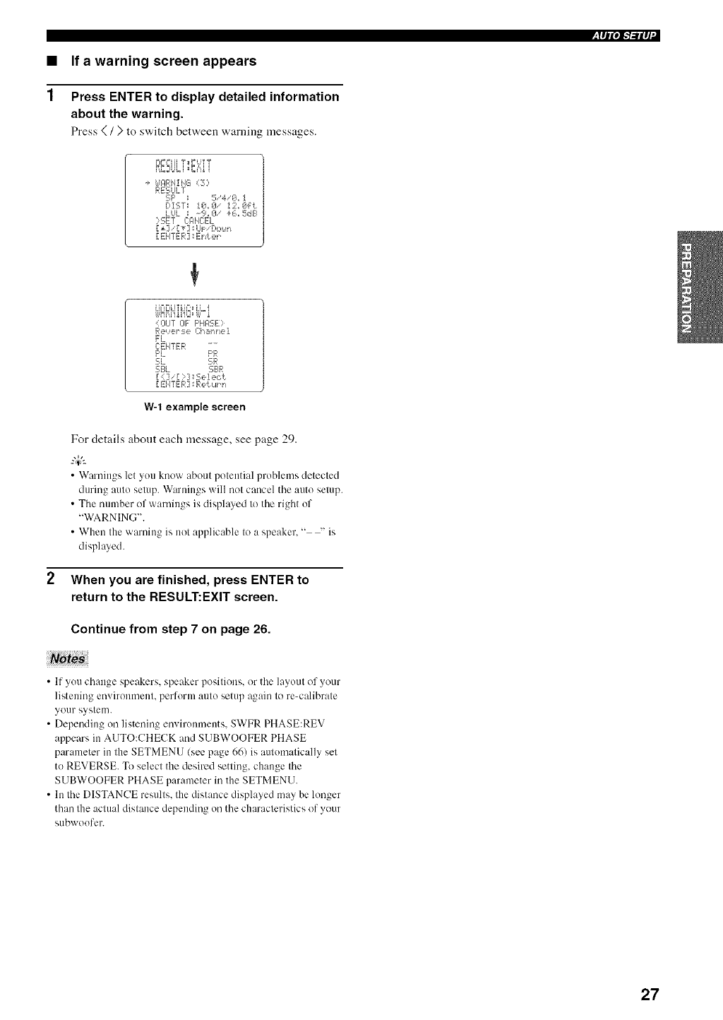
If a warning screen appears
Press ENTER to display detailed information
about the warning.
Press {/) to switch between warning messages.
illli'IN-ilq'I
-+ _dARN!NS,3?
RESULT
5F' ; 5,4/0,, J
DIST: !0,,0'!2,,&Fi
LUL _ -%,1Z1/ +6,,SdB
35:E7 C:ANCE]
[ EHI'ER] : E}/t e_
<OUT OF F'HAS:E?
Reuer :_,e C:h_ht/e t
FL
L-EHTER
F'L F'R
SL SR
5E:L 5;BR
[: ] '[?]:Se!ecf.
[ EiITER ] _Pei. Ul_h
W-1 example screen
For details about each message, see page 29.
• Warnings let you know about potential problems detected
during auto setup. Warnings will not cancel the auto setup.
• The number of warnings is displayed to the right of
"WARNING".
• When the warning is not applicable to a speaker, " -' is
displayed.
When you are finished, press ENTER to
return to the RESULT:EXIT screen.
Continue from step 7 on page 26.
•If you change speakers, speaker positions, or the layout of your
listening environment, perform auto setup again to re-calibrate
your system.
• Depending on listening environments. SWFR PHASE:REV
appears in AUTO:CHECK and SUBWOOFER PHASE
parameter in the SETMENU/see page 66) is automatically set
to REVERSE. To select the desired setting, change the
SUBWOOFER PHASE parameter in the SETMENU.
• In the DISTANCE results, the distance displayed may be longer
than the actual distance depending on the characteristics of your
subwoufer.
27
I_ llil,/-'/-ill, f"
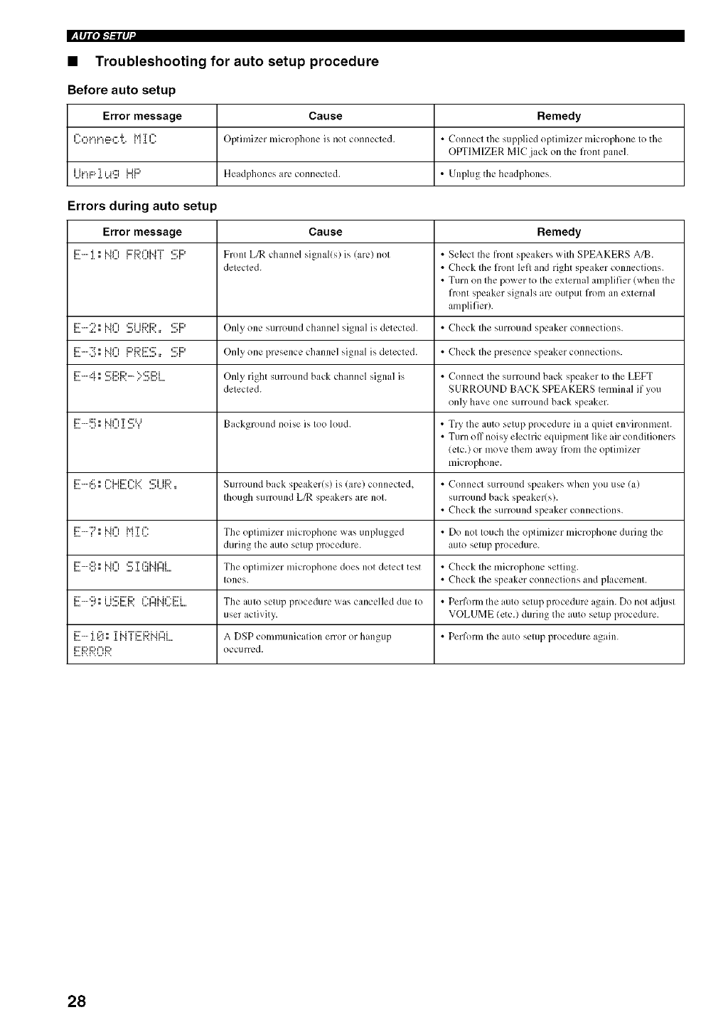
•Troubleshooting for auto setup procedure
Before auto setup
Error message Cause Remedy
I :r',v,i."n::ar'.'L r,'l I I : Optimizer microphone is not connected+ • Connect the supplied optimizer microphone to the
OPTIMIZER MlC.jack on the flont panel.
Ui"!F::' ].i..4g HF:' Headphones are connecled. • Unplug the headphones.
Errors during auto setu
Error message Cause Remedy
l..,+i:::L"".i. ,, i_=...,'i• H+"= li:::'i:::'+"H"i"V{'..,...u_ { ....+I'::H:::+ Front L_ channel signally,) is !arc) nol •Select Ihe front speakers with SPEAKERS A/B.
deleclcd. •Check Ihe front left and right speaker connections.
•Ttlrn on Ihe power to Ihe exlernal amplifier (when Ihe
front speaker signals arc outpul frolil an external
amplifier).
l....i_:_""":'a:..•" IH("i_...' ....'_...'_'.. I'..,._:=iii:::,i._:,• ....q'::H'_:_ Only_ one Sl_lrround channel si_na]_ is detected. •Check Ihe surroulld speaker conllcCtions.
I..,.i::7_.. ":i'....'" I_...'i"il"lli::M:::'i:::"::7_'..L......' • ...._I,::7i:::_ Only one presence channel signal is detected. • Check Ihe presence speaker connections.
i....i::''""i"r." ....,_...,v..,:::'i:::,i:::,.._ ..'"':::'i:::'io..u...,i. Only_ ri_ht_ surround back channel signal is • Connecl Ihe surround back speaker Io Ihe LEFT
delecled. SURROUND BACK SPEAKERS lernlinal if you
only have one surround back speaker.
_....'..................,,, _"uv...,'._._....,........_ Background noise ix Ioo loud. •Try tlle auto selup procedure in a quiel environmenl.
• Turn off noisy elechic equipment like air condilioners
(elc.) or move them away frolIl Ihe optimizer
microphone.
l..,=i::''"_:::_...'." '...=_I'_q...i i::"I'_q..'IL,='...=_"....."...q".'::7iii:::'. Surround back speaker(s) is (are) conllcctcd, • Connecl surroulld speakers wllen yOtl [ISC (a)
Ihough surround L_ speakers are nol. surround back speakerts).
•Check Ihe surround speaker connections.
_..,.i::'"::'_."_i"ir".,*...,_i'd_T._.*....r" The oplimizer microphone was tlnplugged • Do nol Iouch Ihe optimizer microphone during Ihe
during the auto setup procedure, auto selup procedure.
l,,,,i:::'-"*:::'*,,,'." li"il"t','*,,,',,,.":::=,I,T*,,,III'::: H ¢"li",q",q.... The oplimizer microphone does nol detecl test •Check Ihe microphone setting.
Iones. • Check Ihe speaker conneclions and placement.
l,,,.i2:''"*:::t,,,'" ',,.'.,,,q,,,. l'..iJ*:::'i,2:"i:::. *,,,,r".qI"' tu'lH I"' i:::'J".'*....L..t. The aUtO selup procedure x_rilS cancelled due Io •Perforlil the a[llo setup procedure again. Do nol a(ljtlSl
user aclivity. VOLUME {etc.) during the a[llo selup procedure.
l..,.i::F.i. ,:..*.'i t':a,, .I. I ".' _L.._'..I".q".qTi..i"Vi:::'i:::,H ¢"li.... A DSP COllllll[llliCalion error or hilngtlp • Perform Ihe aUtO seiup procedure again.
F:;;?i:;?Di:;? occufred.
28
_|lipi_'/-'ilq" I
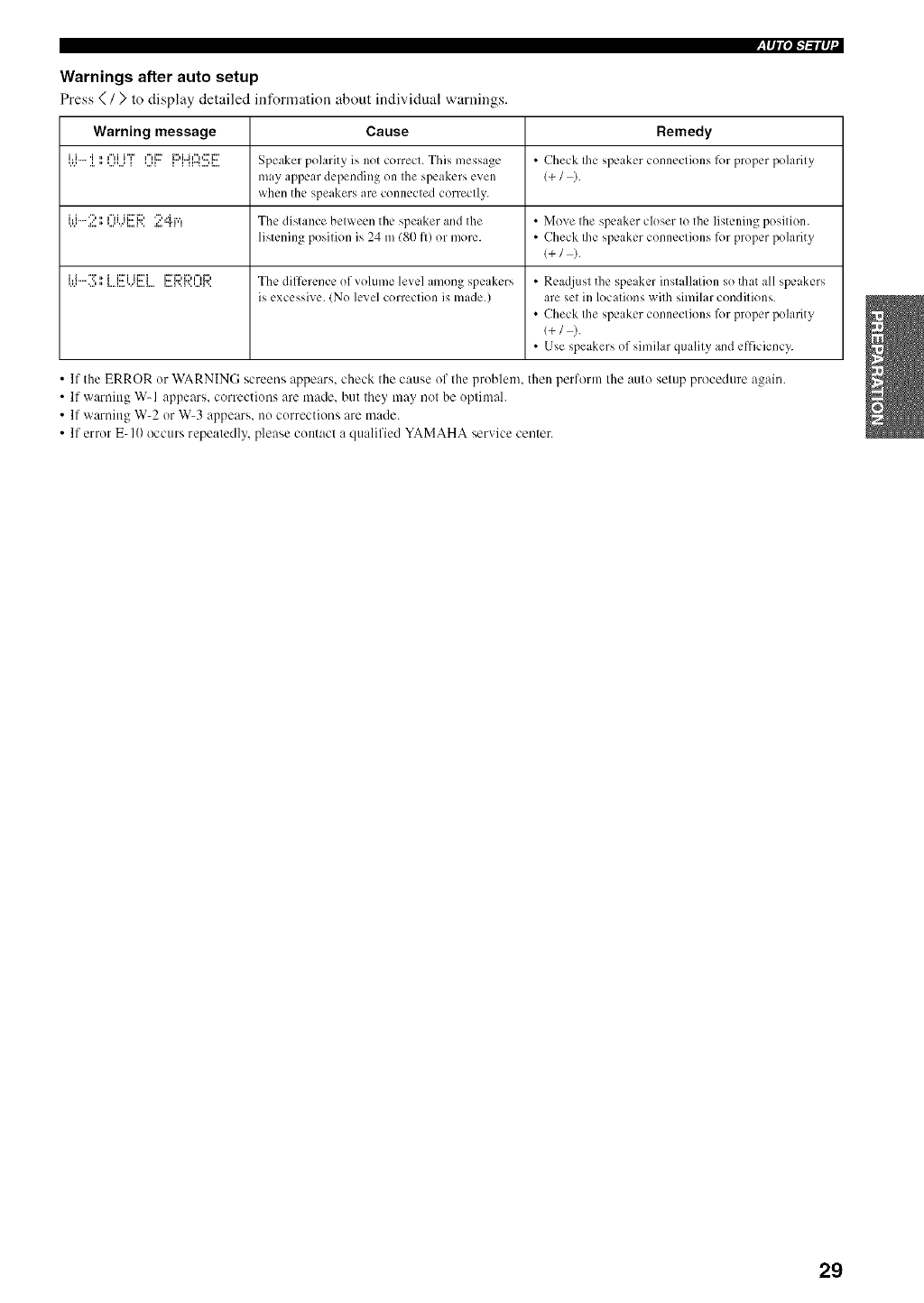
Warnings after auto setup
Press < / > to display detailed information about individual warnings.
Warning message Cause Remedy
[.=J""i ',',0[...i"[" 0F [:::'m[::4'.!!!;[![ Speaker polarity is nol correcl. This message • Check Ihe speaker conncclions l_)r proper polarily
may appear depending on the speakers even l+ /).
when the speakers are connecled correctly.
W2 II0[.)]!!i;). 2=::h','! The distance between the spe iker and the • Move the speaker closer to the listening position.
listening posilion is 24 m/80 l'l) or more. • Check Ihe speaker conneclions lk)r proper polarity
l+ /).
'.'.'i'i""<':i'<,,,,," _...l....'...<_...l....ii::ri ii:::'i l...=l'..l'..'...'l'..i::'i:::'i:::'i=li:::' The dilfercnce of roll.line level imong spe Ikers • Readjusl the speaker installalion so that all speakers
is excessi;_e. (No lex_el correclion is made.) are sel ill locations wilh silnilar condilions.
•Check Ihe speaker conneclions lk)r proper polarity
l+/ ).
• Use speakers of similar qualily and efficiency.
•If the ERROR ur WARNING screens appears, check the cause of the problem, then perform the auto setup procedure again.
• If warning W-1 appears, corrections are made, but they may not be optimal.
• If warning W-2 or W-3 appears, nu corrections are made.
• If error E-I(I occurs repeatedly, please contact a qualified YAMAHA service center.
29
(U.S.A. model
3 7
lm
4-
3-
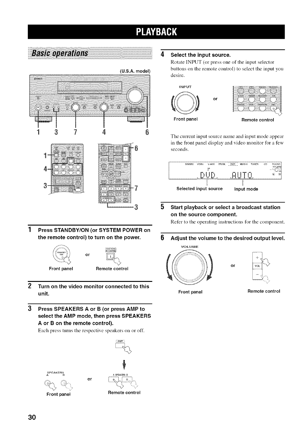
4Select the input source.
Rotate INPUT (or press one of the input selector
buttons on the remote control) to select the input you
desire.
tNPUT
or
Front panel Remote control
The current input source name and input mode appear
in the front panel display and video monitor for a few
seconds.
Dv_wu* vcmi%l i _pvAuxiF'I DTV,e_t D_iim,=li t_DSeD_i7 = m="mruNen cD _ PHONO¢U_IcVOLUpa:_L,g_I,7
Selected input source Input mode
Press STANDBY/ON (or SYSTEM POWER on
the remote control) to turn on the power.
_Y_T_M
[pQWgF_]
or
Front panel Remotecontrol
2Turn on the video monitor connected to this
unit.
3 Press SPEAKERS A or B (or press AMP to
select the AMP mode, then press SPEAKERS
A or B on the remote control).
Each press turns the respective speakers on or off.
SpEAI<En_
A B A SpEaKErS
Front panel Remotecontrol
Start playback or select a broadcast station
on the source component.
Refer to the operating instructions for the component.
Adjust the volume to the desired output level.
VOLUME
(
Front panel Remote control
30
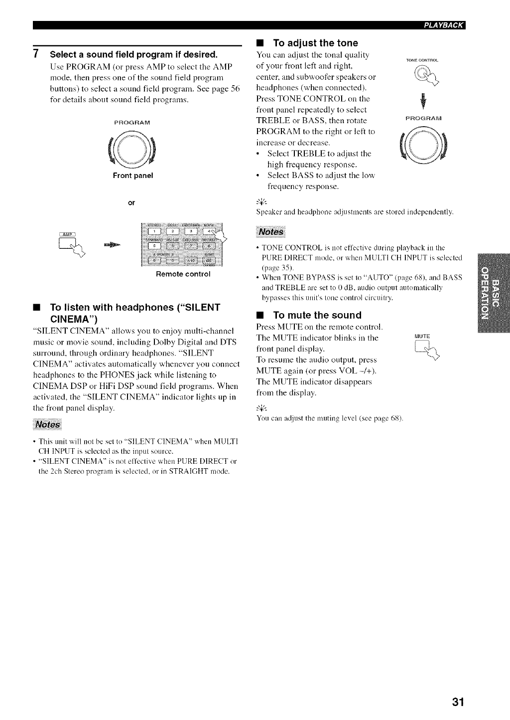
Select a sound field program if desired.
Use PROGRAM (or press AMP to select the AMP
mode, then press one of the sound field program
buttons) to select a sound fiekt program. See page 56
I_r details about sound field programs.
PROGRAM
Front panel
or
Remote control
•To listen with headphones ("SILENT
CINEMA")
"SILENT CINEMA" allows you to enjoy nmlti-channel
nmsic or movie sound, including Dolby Digital and DTS
surround, through ordinary headphones. "SILENT
CINEMA" activates automatically whenever yon connect
headphones to the PHONES jack while listening to
CINEMA DSP or HiFi DSP sound field programs. When
activated, the "SILENT CINEMA" indicator lights up in
the front panel display.
• This unit will not be set tu "SILENT CINEMA" when MULTI
CH INPUT is selected as tile input source.
• "SILENT CINEMA" is not effective when PURE DIRECT ur
the 2ch Stereo program is selected, or in STRAIGHT mode.
,/_ltF_Pf," I
•To adjust the tone
Yon can adjust tile tonal quality ,ONEOO,T_OL
of your front left and right,
center, and subwoofer speakers or
headphones (when connected).
Press TONE CONTROL on the ?
front panel repeatedly to select
TREBLE or BASS, then rotate PROGRAM
PROGRAM to the right or left to
increase or decrease.
• Select TREBLE to adjust the
high frequency response.
• Select BASS to adjust the low
frequency response.
-#-
Speakerand headphone adjustments are stured independently.
• TONE CONTROL is not effective during playback in tile
PURE DIRECT mode, or when MULTI CH INPUT is selected
(page 35).
• When TONE BYPASS is set to "AUTO" (page 68), and BASS
and TREBLE are set tu 0 dB, audio output autumatically
bypasses this unit's tune control circuitry.
•To mute the sound
Press MUTE on the remote control.
The MUTE indicator blinks in the
front panel display.
To resume the audio output, press
MUTE again (or press VOL -/+).
The MUTE indicator disappears
from the display.
_%,.
Yuu can a@lst the muting level (see page 68).
MUTE
31
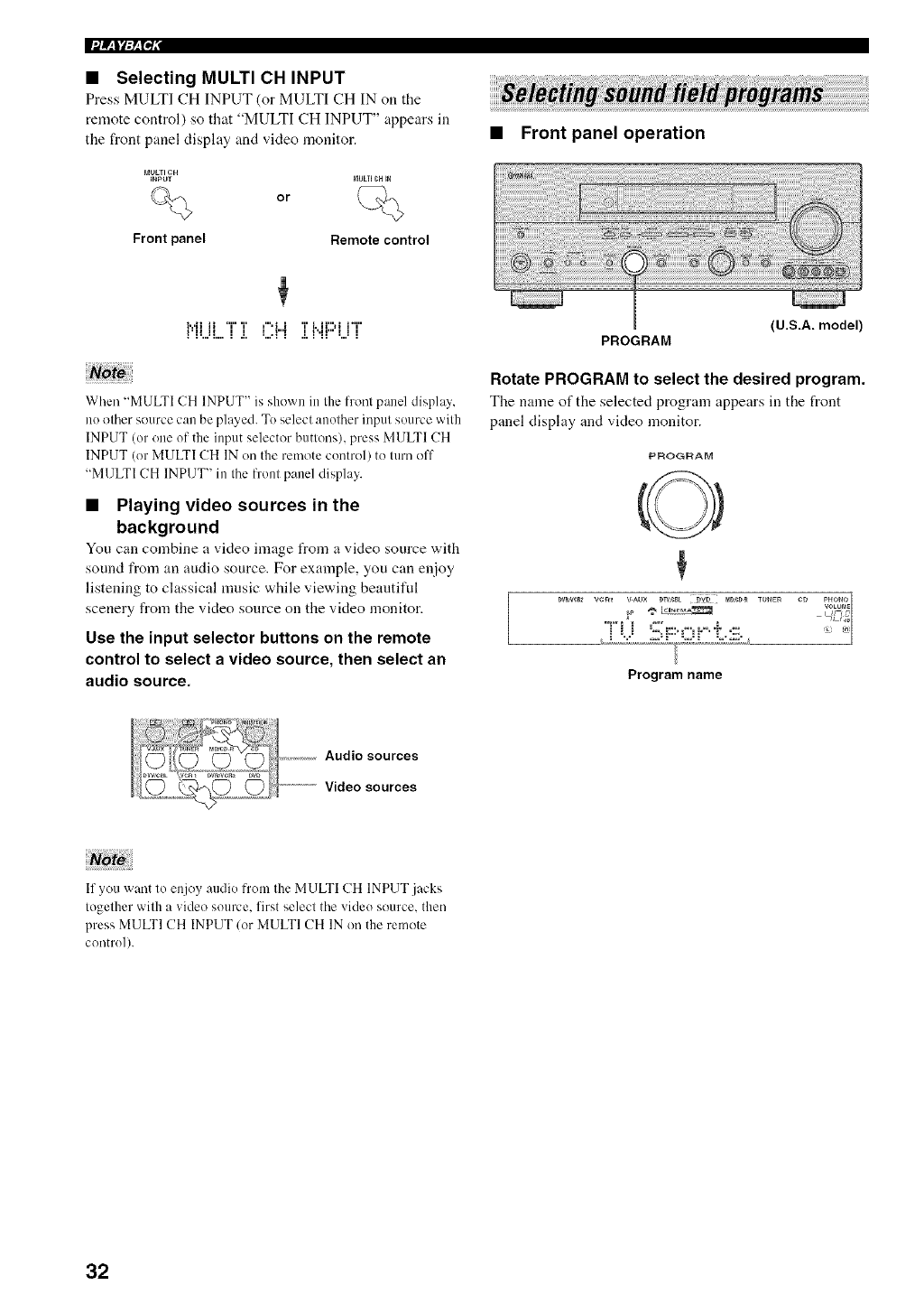
•Selecting MULTI CH INPUT
Press MULTI CH INPUT (or MULTI CH IN on the
remote control) so that "MULTI CH INPUT" appears in
the front panel display and video monitor.
MULTICH
INPUT
%
Front panel
or
NULII CH iN
Remote control
i...ii ii "i" T r",t i T i, lrsi l-i"
UH II I I I ,l"E I U,ll" I 1 I
When "MULTI CH INPUT" is shown in the front panel display,
no other source can be played. To select another input source with
INPUT (or one of the input selector buttonsh press MULTI CH
INPUT (or MULTI CH IN on the remote control) to turn off
"MULTI CH INPUT" in the front panel display.
•Playing video sources in the
background
You can combine a video image from a video source with
sound from an audio source. For example, you can enioy
listening to classical nmsic while viewing beautiful
scenery from the video source on the video monitor.
Use the input selector buttons on the remote
control to select a video source, then select an
audio source.
•Front panel operation
PROGRAM
(U.S.A. model)
Rotate PROGRAM to select the desired program.
The name of the selected program appears in the front
panel display and video monitor.
PROGRAM
Program name
Audio sources
........................Video sources
If you want to enjoy audio from the MULTI CH INPUT.jacks
together with a video source, first select the video source, then
press MULTI CH INPUT/or MULTI CH IN on the remote
control).
32
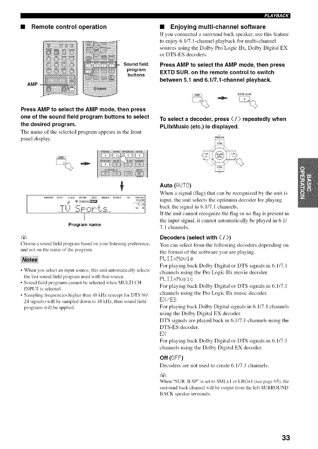
Remote control operation
Sound field
program
buttons
Press AMP to select the AMP mode, then press
one of the sound field program buttons to select
the desired program.
The name of the selected program appears ill the front
panel display.
•/_ItF_P/i" I
•Enjoying multi-channel software
It"yon connected a snrround back speaker, use this feature
to enjoy 6.1/7.1 -channel playback for multi-channel
sources using the Dolby Pro Logic lIx, Dolby Digital EX
or DTS-ES decoders.
Press AMP to select the AMP mode, then press
EXTD SUR. on the remote control to switch
between 5.1 and 6.1/7.1-channel playback.
EXTDSUR
To select a decoder, press < /;, repeatedly when
PLIIxMusic (etc.) is displayed.
A
_AMp ¸
¢
_,,L2_:2,,,,,,,,:_£,_;;}£_,IL,,,,2_;;,;;_L_
Program name
Choose a sound field program based on your listening preference,
and uot ou the uarne of Ihe pro_ranL
•When you select an input source, this unit automatically selects
tile last sound field program used with that source.
• Sound field programs cannot be selected when MULTI CH
INPUT is selected.
• Sampling frequencies higher than 48 kHz (except for DTS 96/
24 signals) will be sampled down to 48 kHz. then sound field
programs will be applied.
Auto (Ai...ii0)
When a signal (flag) that can be recognized by the unit is
input, the unit selects the optimmn decoder for playing
back the signal in 6.1/7.1 channels.
If the unit cannot recognize the flag or no flag is present in
the input signal, it cannot automatically be played in 6.1/
7.1 channels.
Decoders (select with < /))
You can select from the following decoders depending on
the format of the software you are playing.
L'J{ J _ ':¢I"]1"0.. 1 'l g:,
i L...t. 2............
For playing back Dolby Digital or DTS signals in 6.1/7.1
channels nsing the Pro Logic Ilx movie decoder.
i L...t. 2...............
For playing back Dolby Digital or DTS signals in 6.1/7.1
channels using the Pro Logic Ilx nmsic decoder.
L.v ..q.. ,..
1,,,= {" 'i =' 1,,.= ,,,.I
For playing back Dolby Digital signals in 6.1/7.1 channels
using the Dolby Digital EX decoder.
DTS signals are played back in 6.1/7.1 channels using the
DTS-ES decoder.
i::75.:'.
For playing back Dolby Digital or DTS signals in 6.1/7.1
channels using the Dolby Digital EX decoder.
Off (nF::l:::')
Decoders are not used to create 6.1/7.1 channels.
When "SUR. B SP" is set to SMLxl or LRGxl (see page 65), the
surround back chanuel will be output from the left SURROUND
BACK speaker terminals.
33
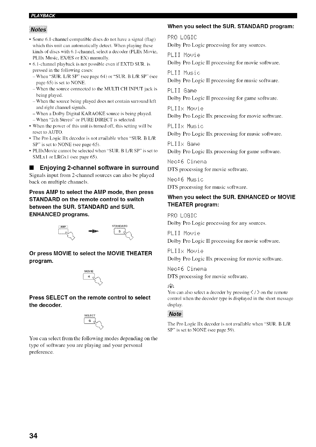
_te_ When you select the SUR. STANDARD program:
•Sume 6. l-claanuel compatible discs do not have a signal/I]ag) _ v..,...,_....,...,,..._._.,....
which this unit can aulumalically detect. When playing these Dolby Pro Logic processing for any sources.
kinds uf discs wilh 6. l-channel, select a decoder (PLIIx Movie ..............
b'L. 1 1 ['IoL._I e
PLIIx Music. EX/ES or EX) manually.
• 6. l-channel playback is not possible even if EXTD SUR. is
pressed in the l'_llowing cases:
When "SUR. L/R SP" (seepage 641 ur "SUR. B L/R SP"/see
page 65) is set to NONE.
When the source connected to the MULTI CH INPUT jack is
being played.
When the source being played clues not contain surruund left
and right channel signals.
When a Dolby Digital KARAOKE source is being played.
When "2ch Stereo" or PURE DIRECT is selected.
• When the power of this unit is turned off. this setting will be
reset to AUTO.
• The Pro Logic llx decoder is not awdlable when "SUR. B L/R
SP" is set to NONE (see page 65).
• PLIlxMovie cannot be selected when "SUR. B L/R SP" is set to
SMLxl or LRGxl (see page 65).
•Enjoying 2-channel software in surround
Signals input from 2-channel sources can also be played
back on multiple channels.
Press AMP to select the AMP mode, then press
STANDARD on the remote control to switch
between the SUR. STANDARD and SUR.
ENHANCED programs.
Dolby Pro Logic II processing for movie software.
Dolby Pro Logic II processing for music software.
F::i....i i (!!iai,*_e
Dolby Pro Logic II processing for game software.
F::i....i ]":.:'H,::,'...'J.e
Dolby Pro Logic Ilx processing for movie software.
PL i ]"":.:'Mi..a:BJ.c
Dolby Pro Logic Ilx processing for music software.
i:)i T T*, l':_,:::trfil:::,
Dolby Pro Logic IIx processing for game sollware.
i"4eO1',6 l":'ii",,:::,r,*,. :::,
DTS processing for movie software.
He O I',I!::, ['l i..4:111.]. ,_:.
DTS processing for music software.
When you select the SUN. ENHANCED or MOVIE
THEATER program:
i2)i:::,,'_ i _"H':::T_"'
i l',,,,J i,,,,,,,,,,,,.i,_._,,,,
Dolby Pro Logic processing for any sources.
I,,,ll _ _ {,,]r,li, j "] g:,
Dolby Pro Logic I] processing for movie software.
Or press MOVIE to select the MOVIE THEATER
program.
MOVIE
Press SELECT on the remote control to select
the decoder.
F::i....i :[*:.='i"i,:::*,...,:i.e
Dolby Pro Logic IIx processing %r movie software.
Neo ',',6 F:.iv.,,:::,r,*,.....
DTS processing for movie software.
-&
You can also select a decoder by, pressing </ >on the renlute
cuntrol 'ahen Ihe decuder lype is displayed in Ihe short message
display.
You can select from the following modes depending on the
type of sollware you are playing and your personal
preference.
The Pru Lugic llx decoder is nutavailable when "SUR. B L/R
SP" is set Io NONE (see page 59).
34
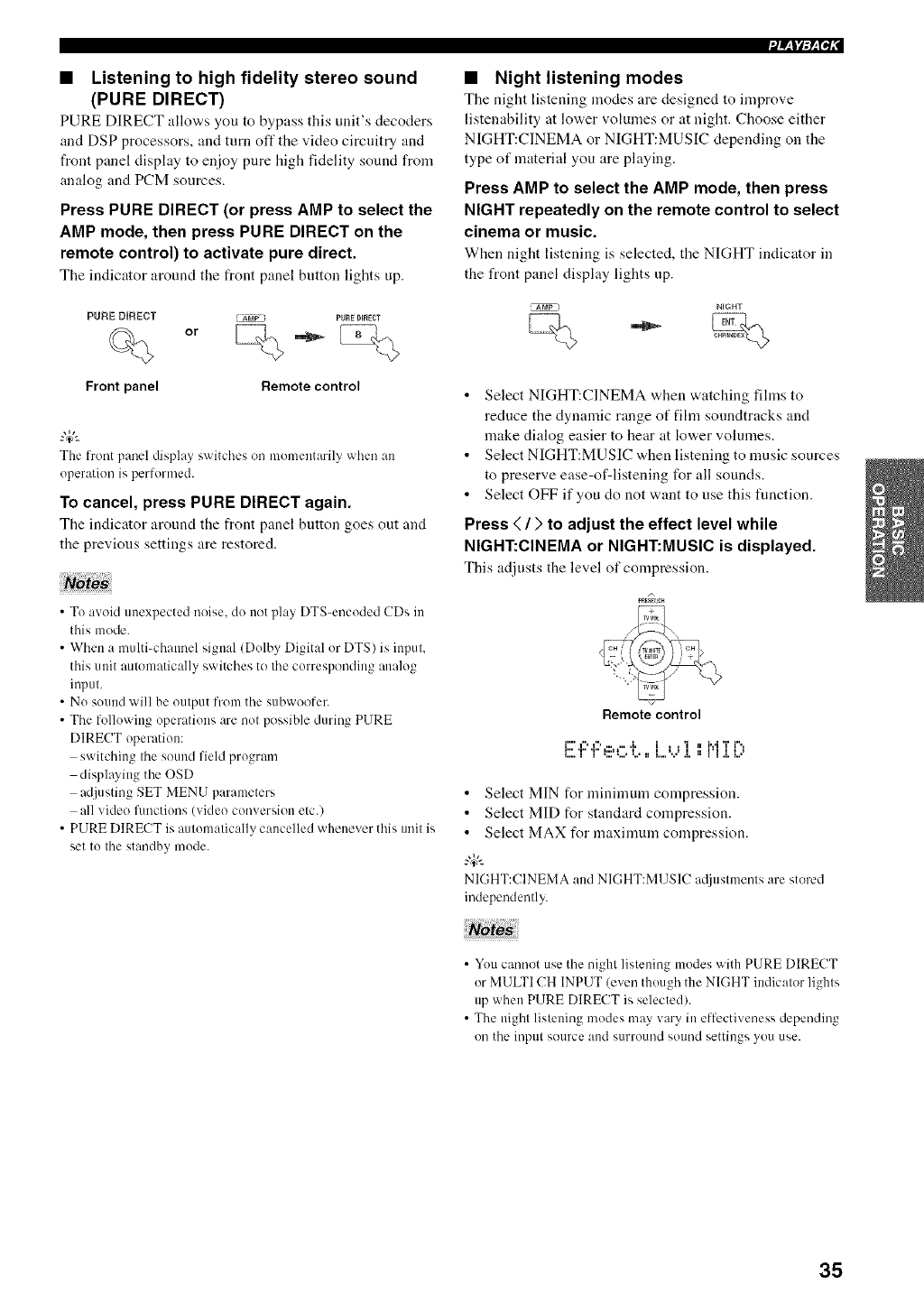
•Listening to high fidelity stereo sound
(PURE DIRECT)
PURE DIRECT allov,.s you to bypass this unit's decoders
and DSP processors, and turn off the video circuitry and
front panel display to enjoy pure high fidelity sound from
analog and PCM sources.
Press PURE DIRECT (or press AMP to select the
AMP mode, then press PURE DIRECT on the
remote control) to activate pure direct.
The indicator around the front panel button lights up.
PURE DIRECT _ Arap PURE DIRECT
%0
Front panel Remote control
The front panel display switches on momentarily when an
operation is performed.
To cancel, press PURE DIRECT again.
The indicator around the front panel button goes out and
the previous settings are restored.
• To avoid unexpected noise, do not play DTS-encoded CDs in
this mode.
• When a multi-channel signal (Dolby Digital or DTS) is input,
this unit automatically switches to tile corresponding analog
input.
•No sound will be output from tile subwoofer.
• The following operations are not possible during PURE
DIRECT operation:
switching the sound field program
displaying the OSD
adjusting SET MENU parameters
all video functions (vkleo conversion etc.)
• PURE DIRECT is automatically cancelled whenever this unit is
set to the standby mode.
•Night listening modes
The night listening modes are designed to improve
listenability at lower volumes or at night. Choose either
NIGHT:CINEMA or NIGHT:MUSIC depending on the
type of material you are playing.
Press AMP to select the AMP mode, then press
NIGHT repeatedly on the remote control to select
cinema or music.
When night listening is selected, the NIGHT indicator in
the front panel display lights up.
NIGHT
•Select NIGHT:CINEMA when watching fihns to
reduce the dynamic range of film soundtracks and
make dialog easier to hear at lower volumes.
• Select NIGHT:MUSIC when listening to music sources
to preserve ease-of-listening for all sounds.
• Select OFF if you do not want to use this function.
Press </>to adjust the effect level while
NIGHT:CINEMA or NIGHT:MUSIC is displayed.
This adjusts the level of compression
Remote control
i"',",,", ...... ,i, 1 , ,'i ,, 1,,,IT i",,
_:::i 1 II T' _:::1 _iii I llll == _IIII JlllJ ,I, ii _ I I ,I, _ii lj
•Select MIN for minimum compression.
•Select MID for standard compression.
• Select MAX for maximum compression.
-#-
NIGHT:CINEMAand NIGHT:MUSIC a@lstments are stored
independently.
•You cannot use tile night listening modes with PURE DIRECT
or MULTI CH INPUT (even though the NIGHT indicator lights
up when PURE DIRECT is selected).
• The night listening modes may wiry in effectiveness depending
on tile input Sotlrce and stlrround SOlllld settings yotl rise.
35
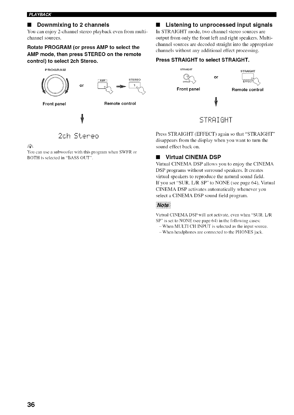
•Downmixing to 2 channels
You can enjoy 2-channel stereo playback even from nmlti-
channel sources.
Rotate PROGRAM (or press AMP to select the
AMP mode, then press STEREO on the remote
control) to select 2ch Stereo.
PROGRAM
or
Front panel Remote control
,"" t"'.i,
You can use a subwoofer with this program when SWFR or
BOTH is selected in "BASS OUT".
•Listening to unprocessed input signals
In STRAIGHT mode, t'a,o channel stereo sources are
output from only the front left and right speakers. Multi-
channel sources are decoded straight into the appropriate
channels without any additional effect processing.
Press STRAIGHT to select STRAIGHT.
or
STRAIGHT
Front panel Remote control
l"""i"i""H""I'i"l"'ii'i"
",It'rh,,Jlt"H"ll
....'II',II,I,',,,IIII
Press STRAIGHT (EFFECT) again so that "STRAIGHT"
disappears from the display when you want to turn the
sound effect back on.
• Virtual CINEMA DSP
Virtual CINEMA DSP allows you to enjoy the CINEMA
DSP programs without surround speakers. It creates
virtual speakers to reproduce the natural sound field.
If you set "SUR. L/R SP" to NONE (see page 64), Virtual
CINEMA DSP activates automatically whenever you
select a CINEMA DSP sound field program.
Note
Virtual CINEMA DSP will not activate, even when "SUR. L/R
SP" is set to NONE (see page 64) in the following cases:
When MULTI CH INPUT is selected as the inpul source.
When headphones are connected Io the PHONES jack.
36
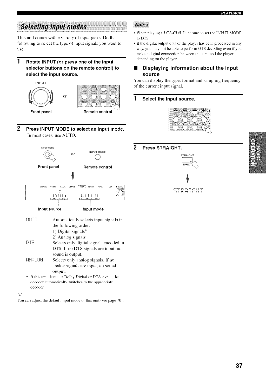
J_llF_['li" I
This unit comes with a variety of input .jacks. Do the
following to select the type of input signals you want to
use,
1 Rotate INPUT (or press one of the input
selector buttons on the remote control) to
select the input source.
INPUT
or
Front panel
•When playing a DTS-CD/LD, be sure to set the INPUT MODE
to DTS.
• If tile digital output data of the player has been processed in any
way, you may not be able to perform DTS decoding even if you
make a digital connection between this unit and the player
depending on the player.
•Displaying information about the input
source
Youcan display the type, format and sampling frequency
of the current input signal.
1 Select the input source.
2Press INPUT MODE to select an input mode.
In most cases,use AUTO.
or INPUT IVlODE
Front panel Remote control
:9
Dv_,w_2 w:nl v _ux DTV,_L DVD _m,r;_ TUNER C[_ PHONO
qOL_JME
Pui iF_ C;_i i'T"I"B _'
Input source Input mode
{:::li...i"i'O Automatically selects input signals in
the following order:
1) Digital signals ,_
2) Analog signals
[:"T".!!; Selects only digital signals encoded in
DTS. If no DTS signals are input, no
sound is output.
{:::ll".il::iL..(](!!i Selects only analog signals. If no
analog signals are inpnt, no sound is
outpnt,
".: If this unit detects a Dolby Digital or DTS signal, the
decoder automatically switches to the appropriate
decoder.
You can ac0ust the default input mode of this unit/see page 70).
2Press STRAIGHT.
STRAIGHT
t"'"i"i"H"l T i",i i"i"
": I l'l: I"I I I "I I"I I
37
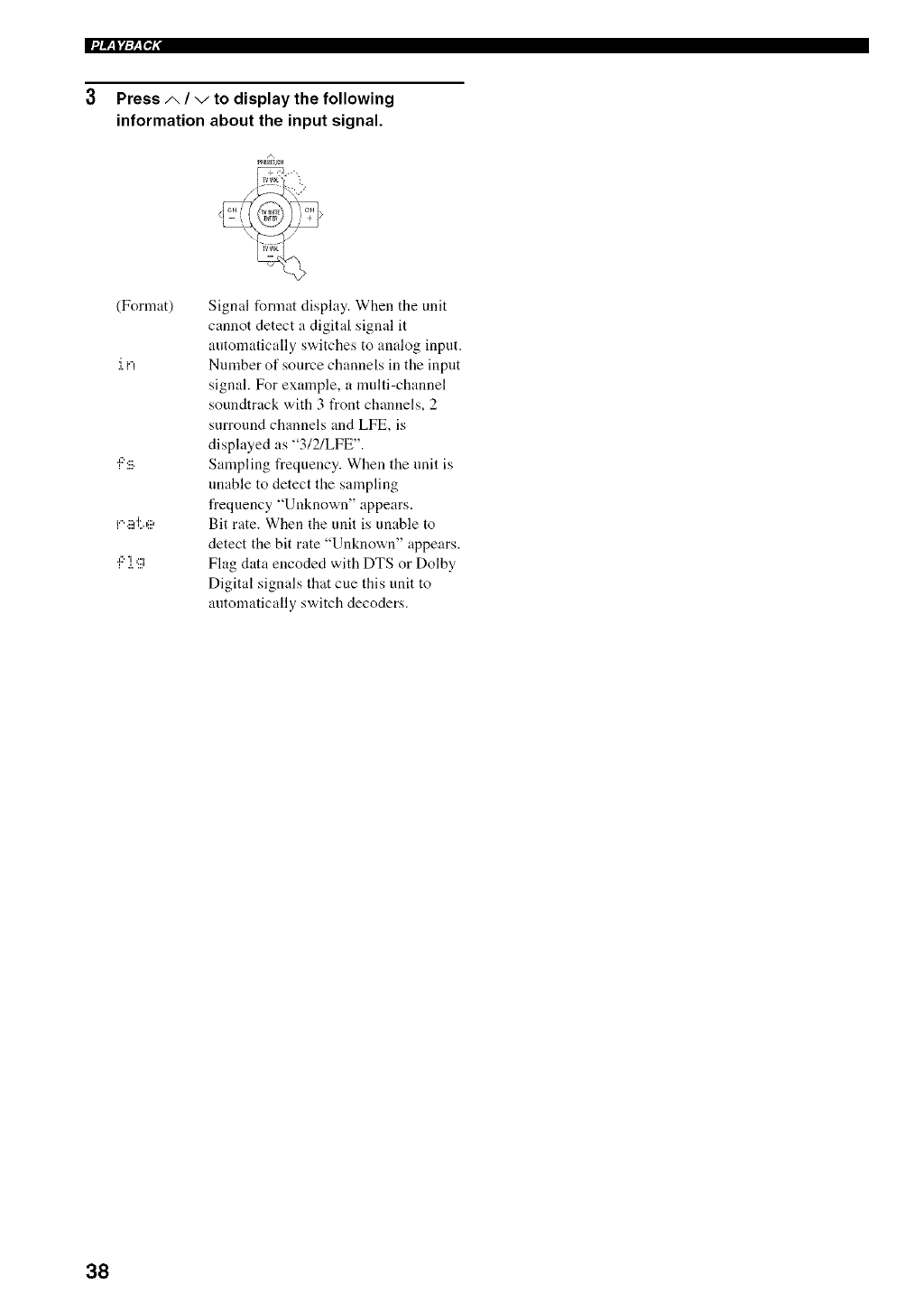
3 Press ,i,,I",/todisplay the following
information about the input signal.
(Format)
:i.i",
Signal format display. When the unit
cannot detect a digital signal it
automatically switches to analog input.
Number of source channels in the input
signal. For example, a multi-channel
soundtrack with 3 front channels, 2
surround channels and LFE, is
displayed as "3/2/LFE".
Sampling frequency. When the unit is
unable to detect the sampling
frequency "Unknown" appears.
Bit rate. When the unit is unable to
detect the bit rate "Unknown" appears.
Flag data encoded with DTS or Dolby
Digital signals that cue this unit to
antomatically switch decoders.
38
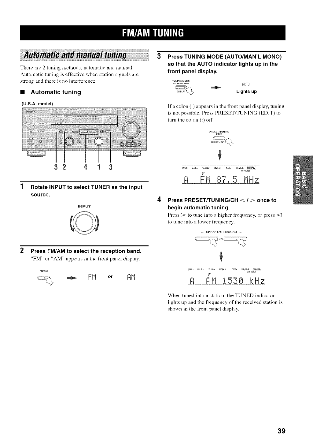
There are 2 tuning methods; automatic and manual.
Automatic tuning is effective when station signals are
strong and there is no interference.
•Automatic tuning
(U.S,A. model)
32 4 1 3
Rotate INPUT to select TUNER as the input
source.
INPUT
Press TUNING MODE (AUTO/MAN'L MONO)
so that the AUTO indicator lights up in the
front panel display.
TU_N_ MOOE
_-_ -- Lights up
lfa colon (:) appears in the front panel display,, tuning
is not possible. Press PRESET/TUNING (EDIT) to
turn the colon (:) off.
pRESET/TUNING
EDIT
_p
Press PRESET/TUNING/CH <3/_> once to
begin automatic tuning.
PressC:>to tuneinto a higher frequency, or press<3
to tune into a lower frequency.
Press FM/AM to select the reception band.
"FM" or "AM" appears in the flout panel display.
i"' i,,,i _"_i,,,i
When tuned into a station, the TUNED indicator
lights up and the frequency of the received station is
shown in the front panel display.
39
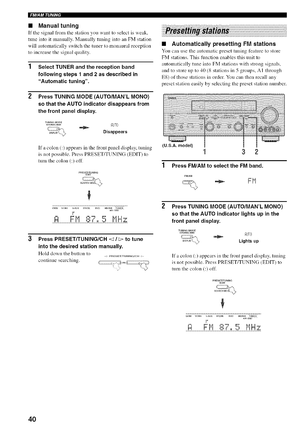
Ii++r,_f++llq_'#_'I,
•Manual tuning
If the signal from tile station you want to select is weak,
tune into it manually. Manually tuning into an FM station
will automatically switch the tuner to monaural reception
to increase the signal quality.
1 Select TUNER and the reception band
following steps 1 and 2 as described in
"Automatic tuning".
Press TUNING MODE (AUTO/MAN'L MONO)
so that the AUTO indicator disappears from
the front panel display.
TUm.GMODE AUTO
If a colon (:) appears in the front panel display, tuning
is not possible. Press PRESET/TUNING (EDIT) to
turn the colon (:) oft'.
Press PRESETFI'UNING/CH <1 /E:>to tune
into the desired station manually.
Hold down the button to pr_ESET/TIJN_NG_C'_4
continue searching.
•Automatically presetting FM stations
You can use the automatic preset tuning feature to store
FM stations. This function enables this unit to
automatically tune into FM stations with strong signals,
and to store up to 40 (8 stations in 5groups, AI through
ES) of those stations in order. You can then recall any
preset station easily by selecting the preset station number.
(U.S.A. model) 13 2
1 Press FM/AM to select the FM band.
FM_AM
i"' i,,,i
PH Ill
Press TUNING MODE (AUTO/MAN'L MONO)
so that the AUTO indicator lights up in the
front panel display.
TUNINC_mODE
++0++_+_+ AUTO
_Lightsup
lfa colon (:) appears in the front panel display, tuning
is not possible. Press PRESET/TUNING (EDIT) to
turn the colon (:) oft'.
PRESE_TUNIN_
EDIT
+
_cR2 veto vAu× D+v,cm _w m_c_ ffu_E_
_um _um_
+_'+ !" !,,,! +% ,-+_ t+-+, M ! ! ,+,
P'+ !"!'! ,::)¢++.j +'!!,],d,'
40
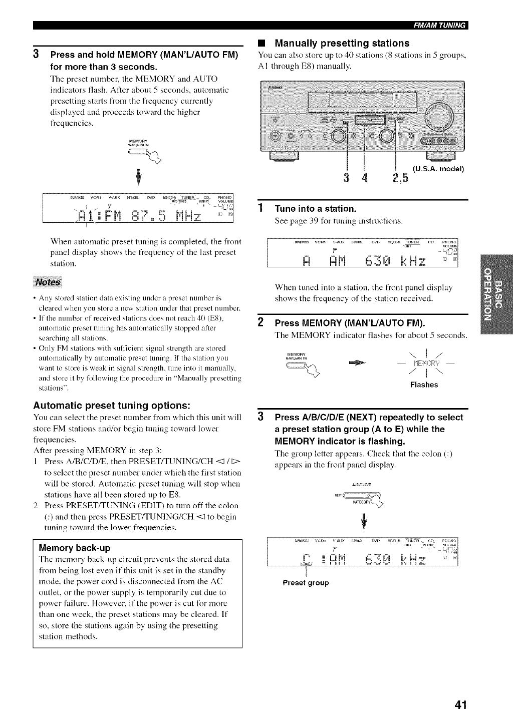
Press and hold MEMORY (MAR'L/AUTO FM)
for more than 3 seconds.
The preset number, the MEMORY and AUTO
indicators flash. After about 5 seconds, automatic
presetting starts from the frequency currently
displayed and proceeds to'a, ard the higher
frequencies.
MEMORY
When automatic preset tuning is completed, the front
panel display shows the frequency of the last preset
station.
• Any stored station data existing under a preset number is
cleared when you store a new station under that preset number.
• If the nmnber of received stations does not reach 4(1 (E8),
automatic preset tuning has automatically stopped after
searching all stations.
• Only FM stations with sufficient signal strength are stored
automatically by automatic preset tuning. If the station you
want to store is weak in signal strength, tune into it manually,
and store it by Mlowing the procedure in "Manually presetting
stations".
Automatic preset tuning options:
You can select tire preset number from which this unit v,,ill
store FM stations and/or begin tuning toward lower
frequencies.
Alter pressing MEMORY in step 3:
1 Press A/B/C/D/E, then PRESET/TUNING/CH <1 /C:>
to select the preset number under which the first station
will be stored. Automatic preset tuning will stop when
stations have all been stored up to ES.
2 Press PRESET/TUNING (EDIT) to turn off the colon
(:) and then press PRESET/TUNING/CH <:1to begin
tuning toward the lower frequencies.
Memory back-up
The memory back-up circuit prevents tire stored data
from being lost even if this unit is set in the standby
mode, the power cord is disconnected from the AC
outlet, or the power supply is temporarily cut due to
power failure. However, if the power is cut for more
than one week, the preset stations may be cleared. If
so, store the stations again by using the presetting
station methods.
•Manually presetting stations
You can also store up to 40 stations (8 stations in 5 groups,
A I through E8) manually.
(U.S.A. model)
3 4 2,5
1Tune into a station.
See page 39 for tuning instructions.
DV_'_R2 VCm V _UX BWtrmt [_VD _m¢_ tUNER CD PHOTO
_UN_ VOWmE
I:;I a i,l ct"::i;:l b i.4.-....
u i i i %.' %.' %., i ', u i ,_.
When tuned into a station, the front panel display
shows the frequency of the station received.
2Press MEMORY (MAR'L/AUTO FM).
The MEMORY indicator fhtshes for about 5 seconds.
Flashes
Press AIBICIDIE (NEXT) repeatedly to select
a preset station group (A to E) while the
MEMORY indicator is flashing.
The group letter appears. Check that the colon (:)
appears in the front panel display.
ILl _B
I-' II 0 bi f:; ":( 171 i,' i,.1,:r _
Preset group
41
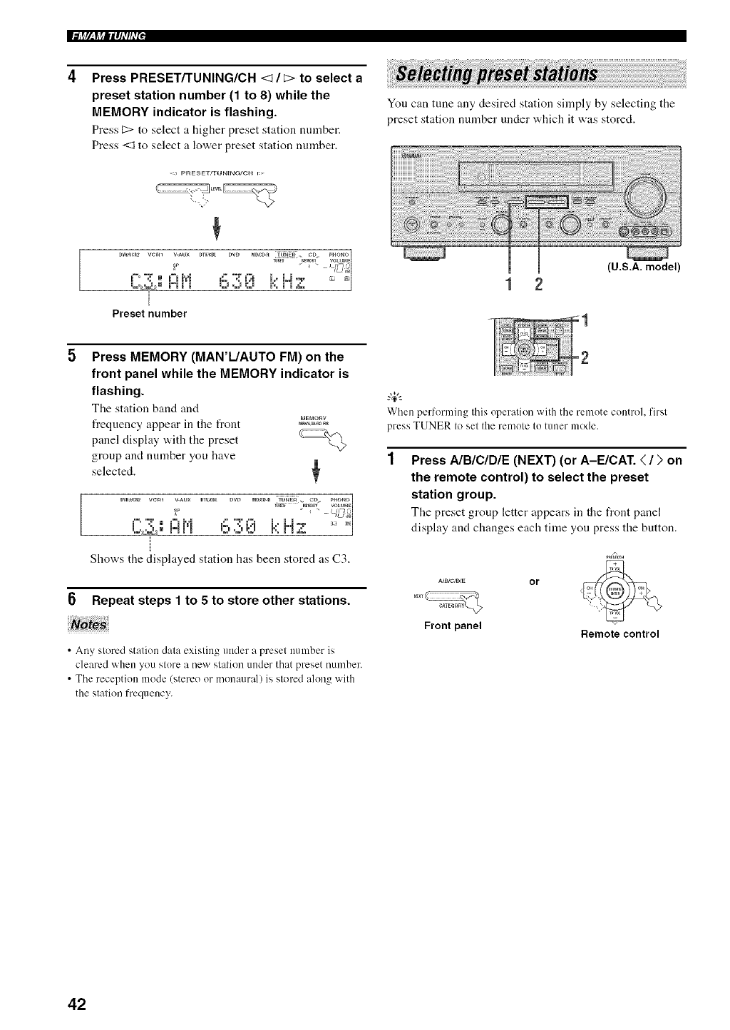
Ii+V,_Yffllq_'#_'I,
Press PRESET/TUNING/CH <t /c> to select a
preset station number (1 to 8) while the
MEMORY indicator is flashing.
Press 1::>to select a higher preset station number.
Press <1 to select a lov,'er preset station number.
You can tune any desired station simply by selecting the
preset station number under which it was stored.
(U.S.A. model)
Press MEMORY (MAN'L/AUTO FM) on the
front panel while the MEMORY indicator is
flashing.
The station band and
frequency appear in the t?ont &.%o+p,_
panel display with the preset CZZ_+'_+
group and number you have
selected.
DVR'_¢++ VCm VAUX DIV,e+t DVD mD+:D_ _tJ++++_ CD pHONO
_b_ • mFm0RY VOLOPaE
i. ....i:it,i +::,..:,L+i k H:;.+: .....
Shows the displayed station has been stored as C3.
Repeat steps 1 to 5 to store other stations.
• Any stored station data existing under a preset number is
cleared when you store a new station under that preset number.
• The reception mode (stereo or monaural) is stored along with
the station frequency.
-&
When performing this operation with the reu'lote control, first
press TUNER to set the remote to tuner mode.
Press AIBICIDIE (NEXT) (or A-E/CAT. </;, on
the remote control) to select the preset
station group.
The preset group letter appears in the front panel
display and changes each time you press the button.
P_E_H
aa_]cm,_ or
Front panel Remote control
42
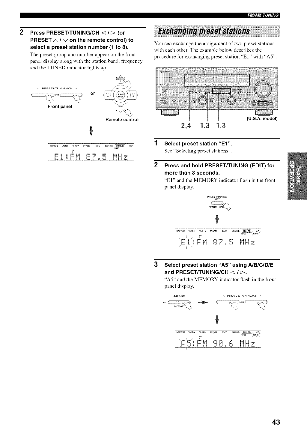
Press PRESET/TUNING/CH <3/c> (or
PRESET/,, /von the remote control) to
select a preset station number (1 to 8).
The preset group and number appear on tile front
panel display along with the station band, frequency
and the TUNED indicator lights up.
<a pRESET/TUNING/CH r_>
or
Front panel
DV_VCR_ VCm V AUX DT_/C_ DVD
_p
L..& ® m ml
Remote control
_D,CD_TUNEn CD
r_g
sj m v _.J m mm mJ_.
You can exchange the assignment of two preset stations
with each other. The example below describes the
procedure for exchanging preset station "El" with "A5".
2,4 1,3 1,3
1 Select preset station "El".
See "Selecting preset stations".
2
(U.S.A. model)
Press and hold PRESET/TUNING (EDIT) for
more than 3 seconds.
"El" and the MEMORY indicator flash in the front
panel display.
pAE_ET_TUNmG
ED_"r
DW,'U_2 VCm V_UX DTV,_t DVD t_gCD_ _t_ r:_
Select preset station "A5" using A/B/C/D/E
and PRESET/TUNING/CH <3/c>.
"A5" and the MEMORY indicator flash in the front
panel display.
A/B/C/D¢_ - _ p_sEr/3 UNIN_/C_ t>
LJ%_I b.F_ ML.t _=.. NM':_
43
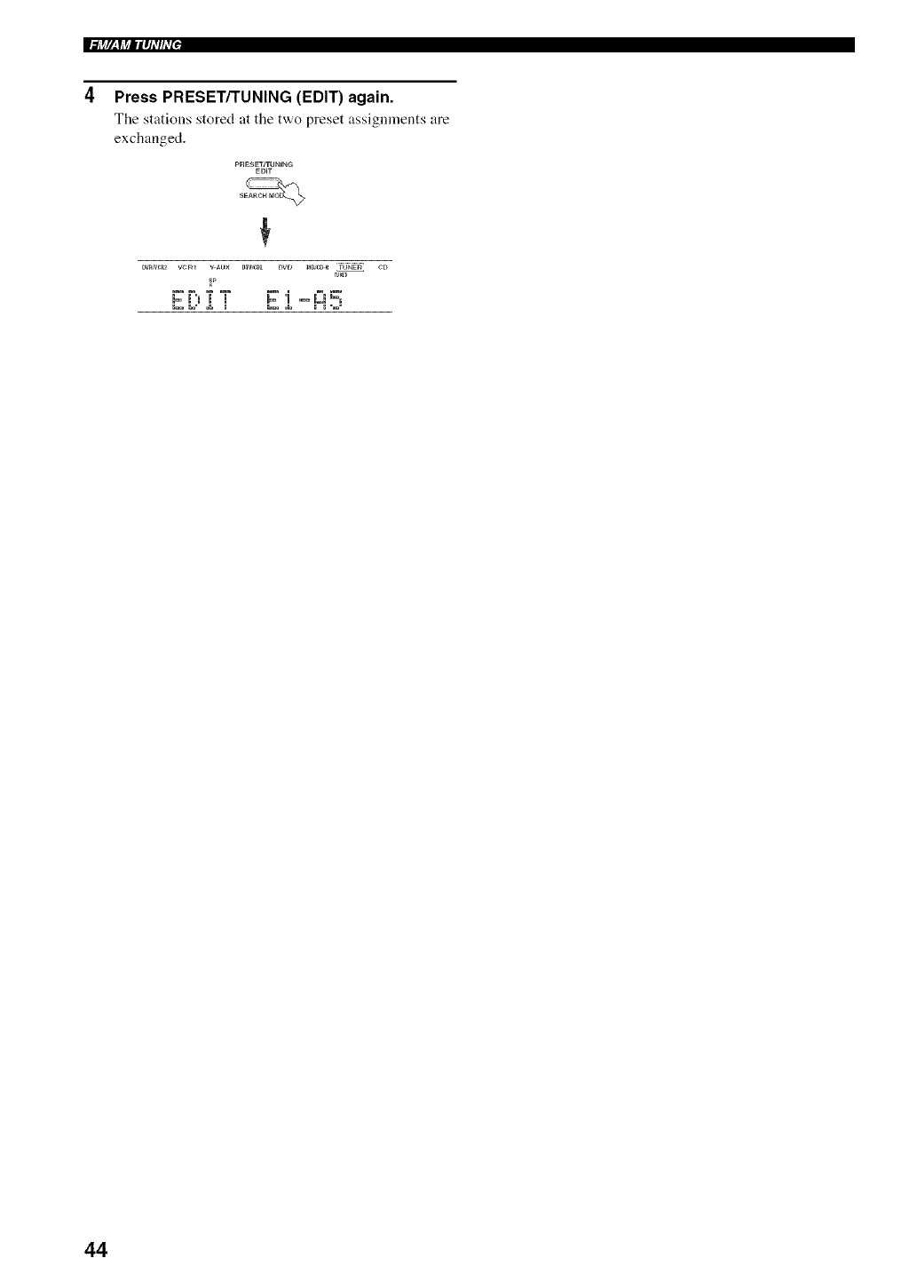
li'++r,_y++ll_J_,#_,+,
Press PRESET/TUNING (EDIT) again.
Tile stations stored at the two preset assignments are
exchanged.
PRESEWTUNING
ED+T
Dw,v_2 vcm v _u× mv,_t DVD mg_D _ TUNE_ CD
r_
i::'r"m'r'i" _:'i .- I"J=;
44
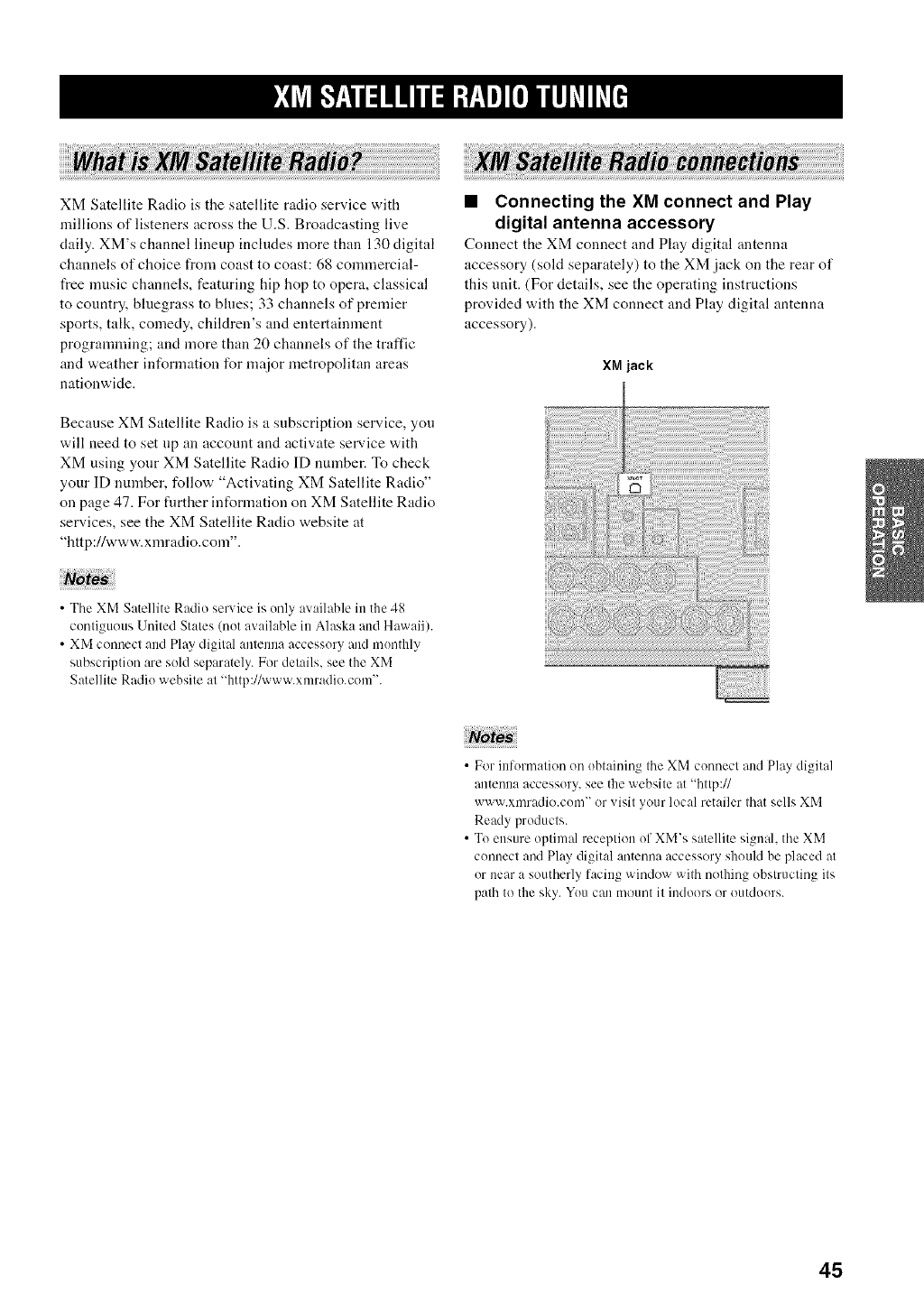
XM Satellite Radio is the satellite radio service with
millions of listeners across the U.S. Broadcasting live
daily. XM's channel lineup includes more than 130 digital
channels of choice from coast to coast: 68 commercial-
t_ee music channels, featuring hip hop to opera, classical
to country, bluegrass to blues; 33 channels of premier
sports, talk, comedy, children's and entertainment
programming; and more than 20 channels of the traffic
and weather information for major metropolitan areas
nationwide.
•Connecting the XM connect and Play
digital antenna accessory
Connect the XM connect and Play digital antenna
accessory (sold separately) to the XM jack on the rear of
this unit. (For details, see the operating instructions
provided with the XM connect and Play digital antenna
accessory).
XM jack
Because XM Satellite Radio is a subscription service, you
will need to set np an account and activate service with
XM using your XM Satellite Radio ID number. To check
your ID number, follow "Activating XM Satellite Radio"
on page 47. For timber information on XM Satellite Radio
services, see the XM Satellite Radio website at
"http://www.xmradio.com".
•The XM Satellite Radio service is only available in the 48
contiguous United States (not available in Alaska and Hawaii).
• XM connect and Play digital antenna accessory and monthly
subscription are sold separately. For details, see the XM
Satellite Radio website at "http://www.xmradio.com".
• For information on obtaining the XM connect and Play digital
antenna accessory, see the website at "http://
www.xmradio.com" or visit your local retailer that sells XM
Ready products.
• To ensure optimal reception of XM's satellite signal, the XM
connect and Play digital antenna accessory should be placed at
or near a southerly facing window with nothing obstructing its
path to the sky. You can mount it indoors or outdoors.
45
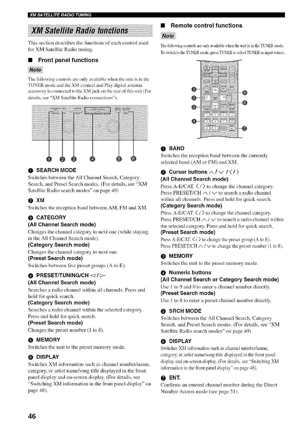
|_(i_l_4|l_||ll:l;y411][Oll|lJdlhT[J
This section describes the functions of each control used
for XM Satellite Radio tuning.
•Front panel functions
•Remote control functions
ThefollowingcontrolsareonlyavailablewhentileunitisintheTUNERmode.
ToswitchtotheTUNERmode,pressTUNERtoselectTUNERasinputsource.
The Mlowing controls are only available when the unit is in the
TUNER mode and the XM connect and Play digital antenna
accessory is connected to the XM .jack on the rear of this unit (For
details, see "XM Satellite Radio connections").
;;iiiiiiiiiiiiiiiiiiiii::
0 SEARCH MODE
Sv,,itches between the All Channel Search, Category
Search, and Preset Search modes. (For details, see "XM
Satellite Radio search modes" on page 49)
O XM
Switches the reception band between AM, FM and XM.
O CATEGORY
(All Channel Search mode)
Changes tile channel category to next one (while staying
in the All Channel Search mode).
(Category Search mode)
Changes the channel category to next one.
(Preset Search mode)
Sv,,itches between five preset groups (A to E).
• PRESET/TUNING/CH <? /c>
(All Channel Search mode)
Searches a radio channel v,,ithin all channels. Press and
hoM for quick search.
(Category Search mode)
Searches :t radio channel vdthin tile selected category.
Press and hold for quick search.
(Preset Search mode)
Ch:mges the preset number (1 to 8).
OMEMORY
S'a,itches tile unit to the preset memory mode.
ODISPLAY
S'a,itches XM information such as channel number/name,
category, or artist name/song title disphtyed in the front
p:mel display and on-screen display. (For details, see
"Switching XM information in the front panel display" on
page 48).
O--
O_
OBAND
Switches the reception b:md between the currently
selected band (AM or FM) and XM.
OCursor buttons/,, /v/</>
(All Channel Search mode)
Press A-E/CAT. ( /) to ch:mge the channel category.
Press PRESET/CH/_ /v to search a radio channel
within all channels. Press and hold for quick search.
(Category Search mode)
Press A-E/CAT. ( /) to change the channel category.
Press PRESET/CH/x /v to search a radio channel within
the selected category. Press and hold for quick search.
(Preset Search mode)
Press A-E/CAT.( /) to change the preset group (A to E).
Press PRESETK_'H/,, /v to change the preset number (1 to 8).
OMEMORY
Switches the unit to the preset memory mode.
•Numeric buttons
(All Channel Search or Category Search mode)
Use 1 to 9 and 0 to enter a channel number directly.
(Preset Search mode)
Use 1 to 8 to enter a preset channel number directly.
O SRCH MODE
S'a,itches between tile All Channel Search, Category
Search, and Preset Search modes. (For details, see "XM
Satellite Radio search modes" on page 49)
ODISPLAY
Switches XM information such as channel number/name,
category, or artist name/song title displayed in the front panel
display'and on-screen display. (For details, see "Switching XM
information in the front panel display" on page 48).
OENT.
Confirms an entered channel number during the Direct
Number Access mode (see page 51 ).
46
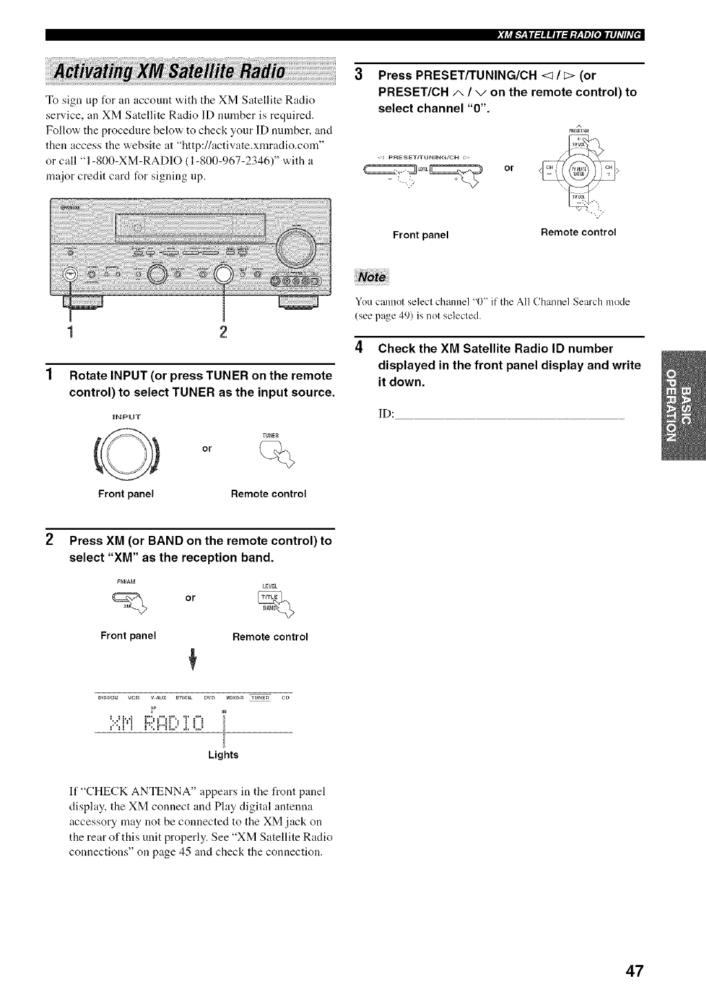
_fj_I.___|I_||iI:I;y__yl][oIIII]_TIhT_::
To sign up for an account with the XM Satellite Radio
service, an XM Satellite Radio ]D number is required.
Follow the procedure below to check your ]D nmnber, and
then access the website at "http://activate.xmradio.com"
or call "1-800-XM-RADIO (1-800-967-2346)" with a
major credit card for signing up.
Press PRESET/TUNING/CH <1/E> (or
PRESET/CH A/von the remote control) to
select channel "0".
A
<J pRE_ET/TUN_NG/CH I>
or
Front panel Remote control
1 2
Rotate INPUT (or press TUNER on the remote
control) to select TUNER as the input source.
tNPUT
TUNE_
or
You cannot select channel "0" if the All Channel Search mode
(see page 49) is not selected.
4Check the XM Satellite Radio ID number
displayed in the front panel display and write
it down.
ID:
Front panel Remote control
Press XM (or BAND on the remote control) to
select "XM" as the reception band.
FPJAM
LEVEL
or
Front panel Remote control
DVnN_2 VCR VAUX DTVm_ DVD _m_-R JUNER CD
_ _, #_ _'% ,"_ _". ,I_ ,,%
?:=i_i i":ii...iL._i. Li
Lights
If "CHECK ANTENNA" appears in the front panel
display, the XM connect and Play digital antenna
accessory may not be connected to the XM jack on
the rear of this unit properly. See "XM Satellite Radio
connections" on page 45 and check the connection.
47
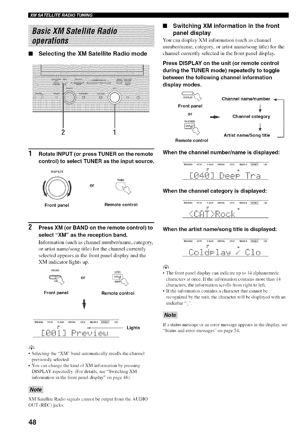
•Selecting the XM Satellite Radio mode
2 1
Rotate INPUT (or press TUNER on the remote
control) to select TUNER as the input source.
iNPUT
TUNE_
or
Front panel Remote control
Press XM (or BAND on the remote control) to
select "XM" as the reception band.
Infomaation (such as channel mnnber/n:une, category,
or artist name/song title) for the channel currently
selected appears in the t_ont panel display and the
XM indicator lights up.
or
Front panel
LEV_L
%
Remote control
•Switching XM information in the front
panel display
You can display XM information (such as channel
number/name, category, or artist name/song title) for the
channel currently selected in the front panel display.
Press DISPLAY on the unit (or remote control
during the TUNER mode) repeatedly to toggle
between the following channel information
display modes.
Channel name/number
Front panel
0°rE._= _ Channel category
Artist name/Song title
Remote control
When the channel number/name is displayed:
Dv_,w_2 vcR v _ux DTV,_L DVD _DJ¢_ rU_ER C_
When the channel category is displayed:
Dw,w_2 w:_ v _u× DTVS_L DW P_D,f:_ TUNER CD
•{i ]-.ii >i'_:h"'_"'.k"
When the artist name/song title is displayed:
{2 ;i ........
•The front panel display can indicate up to 14 alphanumeric
characters at once. If the information contains more than 14
characters, tile information scrolls from right to left.
• If the information contains a character that cannot be
recognized by tile unit. tile character will be displayed with an
underbar "--'.
_ ×_ Lights
[;{i!!{!!!i ] !:::=;''e,-: :[e
•Selecting tile "XM" band automatically recalls the channel
previously selected.
• You can change the kind of XM information by pressing
DISPLAY repeatedly. (For details, see "Switching XM
information in the front panel display" on page 48).
If a slalus message or an error message appears in the display, see
"Status and error messages" on page 54.
XM Satellile Radio signals cannot be output from the AUDIO
OUT/REC/jacks.
48
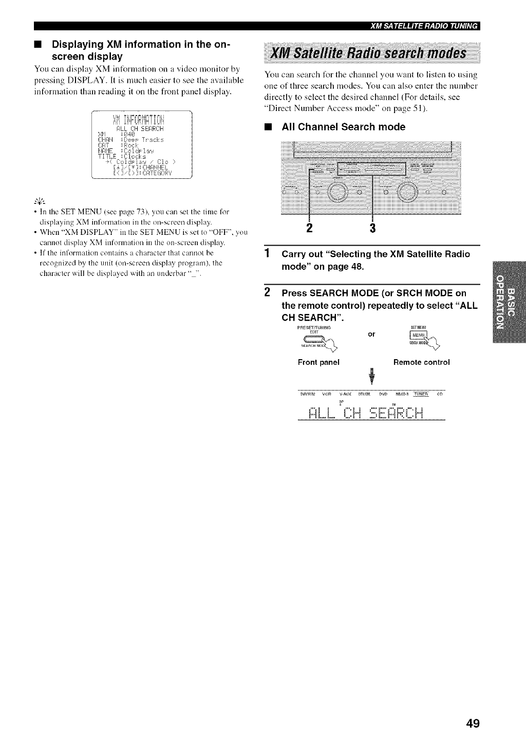
•Displaying XM information in the on-
screen display
You can display XM int`ornmtion on a video monitor by
pressing DISPLAY. It is much easier to see the available
information than reading it on the front panel display.
UN t _IFPIFI_4PIY t PI_i
i'=i'i_i'ir UR[iH[ _Ui'i
RLL CH 5EF_RCH
',,iiI _€14¢1
CHRI'I B,ee,l_ l'I acks
L2nT : Rock
i'41_HE ;C:c,]ds 1::,':#
"TITLE ;C:lc, ck:_
÷_ Cc,ldr_],:,':_ /Clo ?
[_] '[_ 3; CHRNI'4EL
[{ ],[ ? ] _C:F4TEGORV
• In the SET MENU (see page 73), you can set the time for
displaying XM infornmtion in the on-screen display.
• When "XM DISPLAY" in the SET MENU is set to "OFF". you
cannot display XM information in the on-screen display.
• If the information contains a character that cannot be
recognized by the unit (on-screen display program), the
character will be displayed with an underbar "-'.
_[j_I.q_'|I:/||iI:IIY_'yl]goIIIII_TIhT_::
You can search I'or the channel you want to listen to nsing
one of three search modes. You can also enter the number
directly to select the desired channel (For details, see
"Direct Number Access mode" on page 51).
•All Channel Search mode
2 3
1 Carry out "Selecting the XM Satellite Radio
mode" on page 48.
2Press SEARCH MODE (or SRCH MODE on
the remote control) repeatedly to select "ALL
CH SEARCH".
pRESET[TUNING SET N_N/I
.... or _
Front panel Remote control
Dv_ vcR v_ux 0_vsc_L DVD _0,¢0_ IUNER CD
_P X_
["3 L,.. [.... L..'[ _ .... " L... F"; [ % L.." [
49
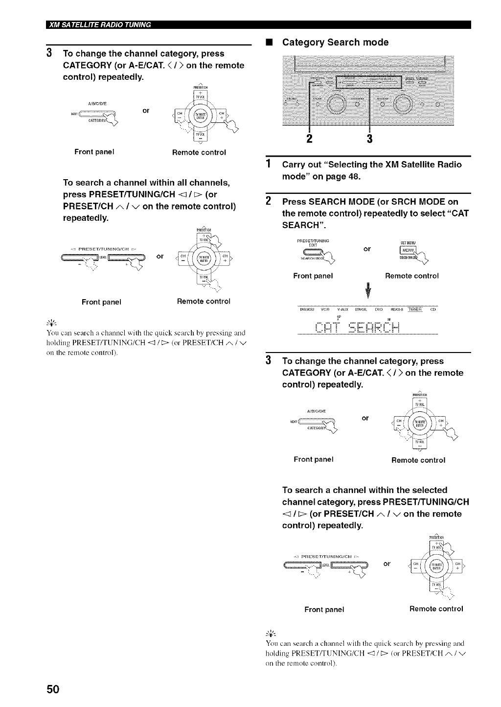
|_j_I.___|I_||iI:I;y__yl][oII|IJ_T/hTIJ
To change the channel category, press
CATEGORY (or A-E/CAT. </>on the remote
control) repeatedly.
NB/C/D/E
or
•Category Search mode
Front panel Remote control
To search a channel within all channels,
press PRESET/TUNING/CH </[> (or
PRESET/CH A/von the remote control)
repeatedly.
<l P_E_ET_NING/CH i>_
or
--,,-
Front panel Remotecontrol
You can search a channel with tile quick search by pressing and
holding PRESET/TUNING/CH<_ /C> (or PRESET/CH/x /"-,/
on the remote control).
2 3
1 Carry out "Selecting the XM Satellite Radio
mode" on page 48.
2Press SEARCH MODE (or SRCH MODE on
the remote control) repeatedly to select "CAT
SEARCH".
PRESET/TONIN_
EDET
Front panel
or
SET_U
Remote control
To change the channel category, press
CATEGORY (or A-E/CAT. </>on the remote
control) repeatedly.
or
Front panel Remote control
To search a channel within the selected
channel category, press PRESET/TUNING/CH
<1 /[> (or PRESET/CH A/von the remote
control) repeatedly.
<1 pRE_E'r_r_NING/CH i>
or
"-. ,-
Front panel Remote control
Youcan search a channel with the quick search by pressing and
holding PRESET_UNING/CH <] /_:>(or PRESET/CH A /v
on the remote control).
50
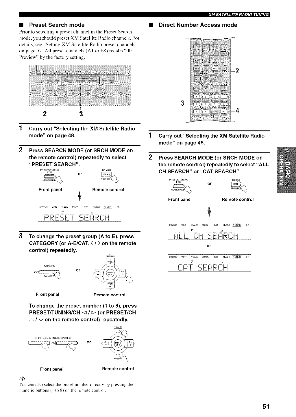
• Preset Search mode
Prior to selecting a preset ch:umel ill the Preset Search
mode, you should preset XM Satellite Radio channels. For
details, see "Setting XM Satellite Radio preset channels"
on page 52. All preset channels (AI to E8) recalls "001
Preview" by the factory setting.
2 3
1 Carry out "Selecting the XM Satellite Radio
mode" on page 48.
2Press SEARCH MODE (or SRCH MODE on
the remote control) repeatedly to select
"PRESET SEARCH".
PRESET/TUNING _[TNE_U
EDn or
Front panel Remote control
To change the preset group (A to E), press
CATEGORY (or A-E/CAT. </>on the remote
control) repeatedly.
A/B/C/D/E
or
_fj_I.___iI_||iI:I;y__yl][olIII_T/hT2::
•Direct Number Access mode
1 Carry out "Selecting the XM Satellite Radio
mode" on page 48.
2Press SEARCH MODE (or SRCH MODE on
the remote control) repeatedly to select "ALL
CH SEARCH" or "CAT SEARCH".
pRESETfrONING _ _E_U
EDIT or
Front panel Remote control
Front panel Remote control
To change the preset number (1 to 8), press
PRESET/TUNING/CH <1 / _> (or PRESET/CH
A/von the remote control) repeatedly.
<J p_E_ET_rUN_NG/C_ I>
or
Front panel Remote control
You can :dso select the preset number directly by pressing tile
numeric buttons (1 to 8) on the remote control.
51
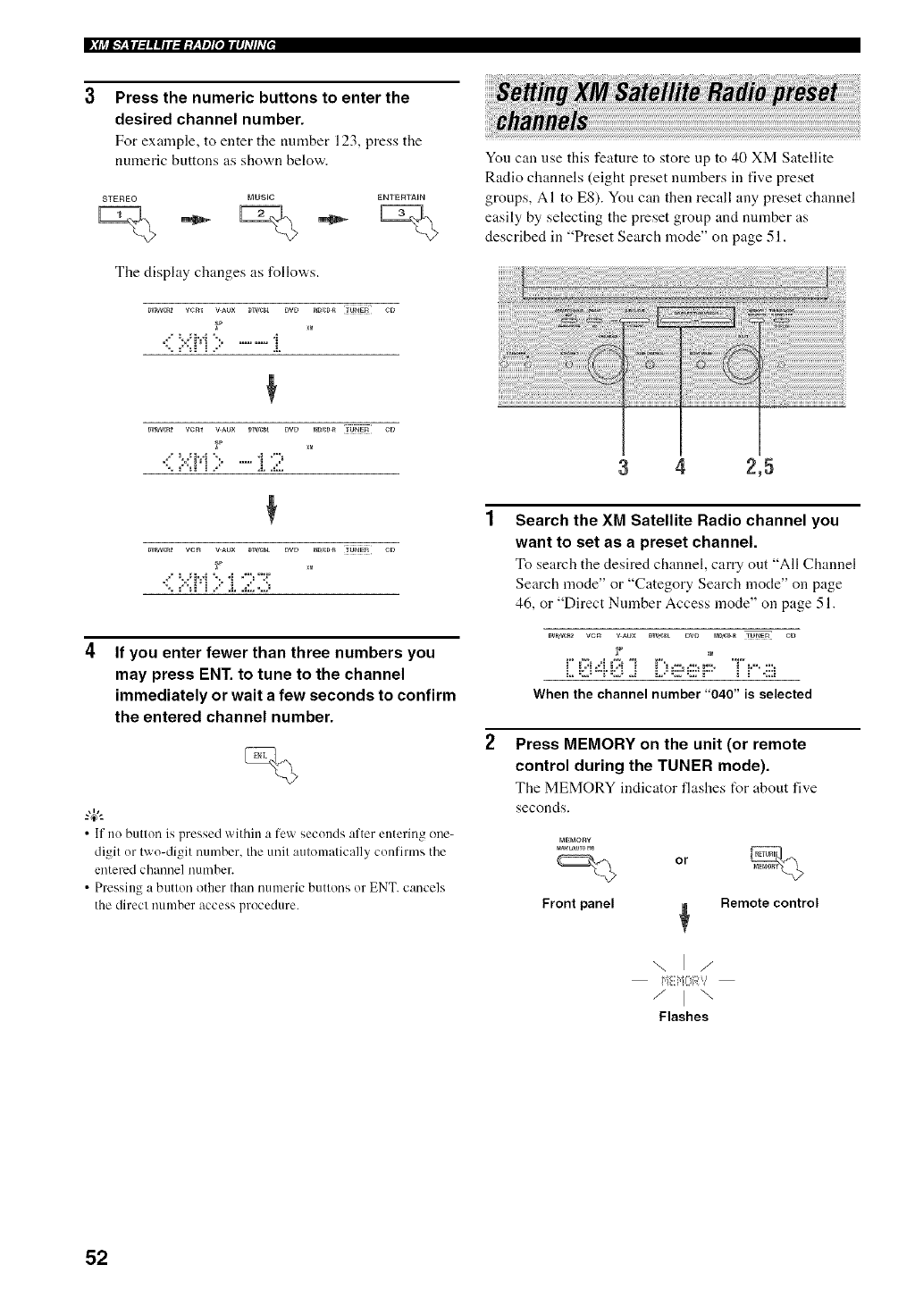
Press the numeric buttons to enter the
desired channel number.
For example, to enter tile mnnber 123, press tile
numeric buttons as shown below.
STEREO MUSIC ENTERTAIN
The display changes as %llows.
0v_vcB_ vcm vAux Dlw_t DVD _0 _ TUNER CD
-XP
If you enter fewer than three numbers you
may press ENT. to tune to the channel
immediately or wait a few seconds to confirm
the entered channel number.
•If no button is pressed within a few seconds after entering one-
digit or two-digit number, tile unit automatically confirms tile
entered channel number.
• Pressing a button other than numeric buttons or ENT. cancels
the direct number access procedure.
You can use this feature to store up to 40 XM Satellite
Radio channels (eight preset numbers in five preset
groups, AI to ES). You can then recall any preset channel
easily by selecting the preset group and number as
described in "Preset Search mode" on page 51.
34 2,5
Search the XM Satellite Radio channel you
want to set as a preset channel.
To search the desired channel, carry out "All Channel
Search mode" or "Category Search mode" on page
46, or "Direct Number Access mode" on page 51.
OVR,VgB2 VCF_ v AU× [}TV,gBL DVD _tDjCB_R TUNER CD
)7
When the channel number "040" is selected
Press MEMORY on the unit (or remote
control during the TUNER mode).
The MEMORY indicator flashes t_r about five
seconds.
_aEMony
or
Front panel
Remote control
"\, I
Flashes
52
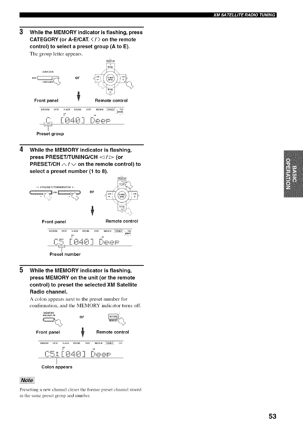
_[j_I__'|I_||iI:I;y_'yl][oIIII]_TIhT_:z
While the MEMORY indicator is flashing, press
CATEGORY (or A-E/CAT. </>on the remote
control) to select a preset group (A to E).
The group letter appears.
or
Front panel Remote control
DVR_F_ VeR V_UX DIVS_L DVD _D,_¢D_ TUNER _
MFMORY
i _,
Preset group
While the MEMORY indicator is flashing,
press PRESET/TUNING/CH <_/_> (or
PRESET/CH A/von the remote control) to
select a preset number (1 to 8).
P_H
<l pRE_ET/T_NtNG/CH i>
or
Front panel Remote control
Mm0RY
Preset number
While the MEMORY indicator is flashing,
press MEMORY on the unit (or the remote
control) to preset the selected XM Satellite
Radio channel.
A colon appears next to the preset number for
confirmation, and the MEMORY indicator turns off.
MEMO_'€
Frontpanel _Remotecontrol
="*,_:::' =_" ="5 ,._ ="5 "t r*,...........
Colon appears
Presetlin_ a new channel clears the former preset channel stored
in the same preset group and number.
53
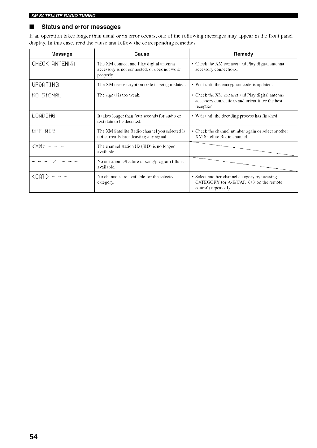
•Status and error messages
If an operation takes longer than usual or an error occurs, one of the following messages may appear in the front panel
display. In this case, read the cause and folio,,,,' the corresponding remedies.
Message
i=.i...i i::? i=. i...* F'I H °r' i::? i. ii. il"l
iiPi":,n"[Tiqf:_
i..iF'l ,;;"T _';2i..hu'_i
=".%., ...., .L _...H",q",%..
iI"ff"d% '}%.i 12_
L,**...'r"i L.* 2.1 'i '..,I
'...ll I I"I .I.r..
.." v tel '.................
............... ...' ...............
Cause
The XM connect and Play digital antenna
accessory is not connecte& or does not work
properly.
The XM user encryption code is being updated.
The signal is too weak.
It takes kruger than four seconds for audio or
lexl dala to he decoded.
The XM Satellite Radio channel you selected is
not currently broadcasting any signah
The channel station ID (SID) is no longer
available.
No artisl name/fealure or song/program lille is
available.
No channels are avaihtble ff)r the selecled
calegory.
Remedy
• Check Ihe XM connect and Play digital antenna
accessory connections.
• Wail until Ihe encryp/ion code is updaled.
• Check the XM connect and Play digital antenna
accessory connections and orient it for the best
reception.
•Wait until the decoding process has finished.
• Check Ihe channel number again or select another
XM Salellite Radio channeh
• Select another channel category by pressing
CATEGORY (or A-E/CAT. </ ) on the remote
control) repeatedly.
54
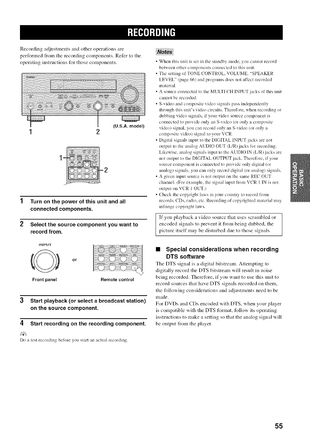
Recording adjustments and other operations are
pert'ormed from the recording components. Refer to the
operating instructions for those components.
(U.S.A. model)
1 Turn on the power of this unit and all
connected components.
2Select the source component you want to
record from.
INPUT
or
Front panel Remote control
3 Start playback (or select a broadcast station)
on the source component.
4Start recording on the recording component.
Do a test recordin_ belore you start an actual recording.
• When this unit is set in the standby mude, yuu cannot record
between uther components connected to this unit.
• The setting of TONE CONTROL, VOLUME, "SPEAKER
LEVEL" (page 66) and programs does not affect recorded
material.
• A source cunnected to the MULTI CH INPUT jacks of this unit
cannot be recorded.
• S-video and composite video signals pass independently
through this unit's video circuits. Therefure, when recording or
dubbing videu signals, if your video source component is
connected to pruvide only an S-video (or only a compusite
video) signal, you can record only an S-video (or unly a
compusite video) signal to your VCR.
• Digital signals input to the DIGITAL INPUT .jacks are not
uutput to the analog AUDIO OUT (L/R)jacks for recording.
Likewise, analog signals input to the AUDIO IN (L/R)jacks are
not output to the DIGITAL OUTPUT.jack. Thereli_re, if your
source component is connected to provide only digital (or
analog) signals, you call only record digital (or aualug) signals.
• A given input suurce is nut output on the same RE(! OUT
channeh (For example, the signal input from VCR 1 IN is (lot
output on VCR 1 OUT.)
• Check the cupyright laws in your country to record Irom
recurds, CDs, radio, etc. Recording of copyrighted material may
infringe copyright laD.rs.
If yOU playback a video source that uses scrambled or
encoded signals to prevent it from being dubbed the
picture itself may be disturbed due to those signals.
•Special considerations when recording
DTS software
The DTS signal is a digital bitstream. Attempting to
digitally record the DTS bitstream will result in noise
being recorded. Therefore, if you want to use this unit to
record sources that have DTS signals recorded on them,
the following considerations and adjustments need to be
made.
For DVDs and CDs encoded with DTS, when your player
is compatible with the DTS format, follow its operating
instructions to make a setting so that the analog signal will
be output from the player.
55
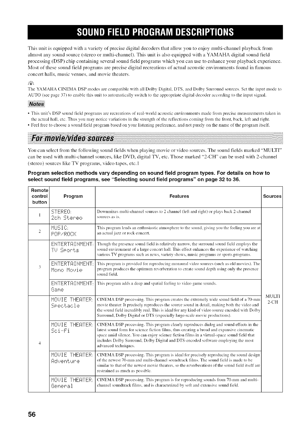
This unit is equipped with a variety of precise digital decoders that allow you to enjoy nmlti-channel playback from
almost any sound source (stereo or multi-channel). This unit is also equipped with a YAMAHA digital sound fiekt
processing (DSP) chip containing several sound field programs which you can use to enhance your playback experience.
Most of these sound field programs are precise digital recreations of actual acoustic environments found in famous
concert halls, music venues, and movie theaters.
The YAMAHA CINEMA DSP modes are compatible with all Dolby Digital. DTS. and Dolby Surround sources. Set the input mode to
AUTO (see page 37) to enable this unit to automatically switch to the appropriate digital decoder according to the input signah
• This unit's DSP sound field programs are recreations of real-world acoustic environments made from precise measuremenls taken in
the aclual l'lall, etc. Thus you may notice _ ariations in the strength of the reflections coming from the front, back. left and right.
• Feel free to choose a sound field program based on your listening preference, and not purely, on the name of the program itself.
You can select from the following sound fields when playing movie or video sources. The sound fields marked "MULTI"
can be used with multi-channel sources, like DVD, digital TV, etc. Those marked "2-CH" can be used with 2-channel
(stereo) sources like TV programs, video tapes, etc. 1
Program selection methods vary depending on sound field program types. For details on how to
select sound field programs, see "Selecting sound field programs" on page 32 to 36.
Remote
control Program Features Sources
button
S"FEp. i!!!I()I Downmixes mulli-channcl sources Io 2 channel (lcfl and right) or plays back 2-channel
12,=.i'3 S'l:..,ii?i"',ii?O sources as is.
{"ll..l'.:::,J.l...:: This program lends an enlhusiastic almosphere Io Ihe sound, giving you Ihe l)eling you are {it
2i::ll'=li::)."i=ll'=ll==D' an actual jazz or rock concerl.
IL.q ,, F,,LjL=F,
I....I_i::'M"Fi='_::I'T'I"_I...._'.._m .I.1'HTMMI:FM'T'.II...I'I I . Though the presence SOtlnd field is relatively_ narrow, the sLirrotlnd soLiild field elIlploys Ihe
"T'Ii ,:::_i:::._...,i._..i...::: sound environment of alarge concert halh This effect enhances the experience of watching
Val'iOtlS WV programs such as news, varielv shows music programs or sports plogralllS.
_....__""a__....v.._''_'' _r".,._.H_'_' _..,,'m.......a'__'' _'." This program is provided l_/rreprodLicing lIlOnitlra] video sources (SLichis old lIlO'_ies).The
3i"h"_i"u",M,"_i..i'i ,::a program produces the oplinmln reverberation to create sound deplh using only Ihe presence
sound field.
_....H_'''J __....v.._''_'' __".,._._'_'_' _..,,'m......,a'__''_'." This _2_r()gr_llIladds _I deep and spatial feeling Io video game soullds.
l.::i.ii_r,=!e
MULTI
I I'..._",".I._...i"ii=lii'i'_1:'"FL.ii::'r'_"r'_i:'i:).l1II..,A"_II....I'... CINEMA DSP processing. This plogranl creates the exnclilelv_wide sound field of i 70-111111 2-CH
c::i:::.,::a_....+..:::_,...'1_:::, movie Iheater.It precisely, reproduces the source sound in detail making both Ihe video and
the sound field incredibly reah This is ideal for any kind of video source encoded with Dolby
Sunound Dolbv Digilal or DTS (especially large-scale movie productions).
I IL..'"," .I._...h'ii%ii'i' _1:' "FL.ii::'rv'r'_i:'i:).l1 II..,=I"_ I I....I'... CINEMA DSP processing. Tiffs program clearly reproduces didog and sound effecls in Ihe
S,=.:i.F:' :i. latest sound lkmn 12/1science ficlion fihns, thus creating i broad and expansive cineln _lic
space amid silence. You can enjoy science ficlion fihns in a virtual-space sound field thai
4 inchldes Dolby Surround, Dolby Digilal and DTS-encoded software employing the most
advanced techniques.
_....,../._._...._""_'_' _" __....m __....v...__"''"'_' _''""" CINEMA DSP processing. This program is ideal for precisely, reproducing Ihe sound design
l:hqLJ_:::,i.",'['.iai."._:::, of the newesl 70-1rimand mulli-channel soundtr ick fihns. The sound field is mtde Io be
silnilar I(1Ihal of the newest movie theaters, so the reverberations of the sound field itself are
restrained as much as possible.
I IL..'",".I.l....i"ii'=lii'i' i=' "FL.ii::'rYT'I'I:'i:).I1 ii..,.i"_ i i....i'... CINEMA DSP processing. Tiffs progran/ is for reprodtlcinK_ SoLinds frolIl 70=111111 and mtl][i=
(!!i,ii?["!eF".ii_]. channel soundhack fihns, and is characlerized by, soft and exlensive sound field.
56
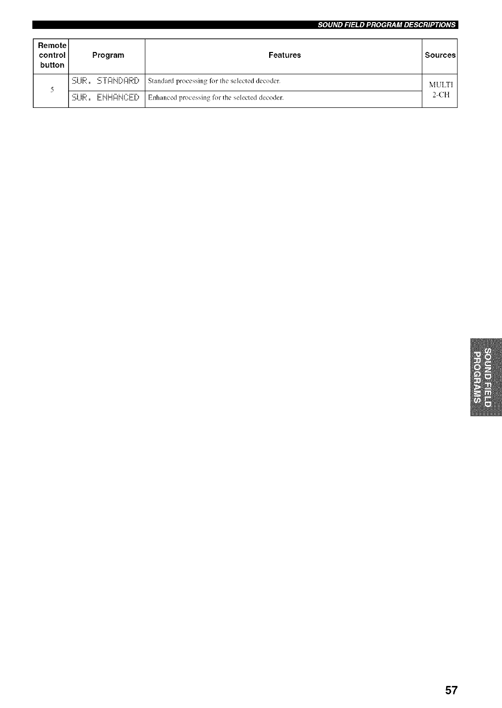
te]#Jdlel_l_lllel".l:£eIel:V_,IJ_le]_e_:ll'Ulg[e]dF -
Remote
control Program Features Sources
button
_...i n..., _... i i nr._ ',l ll...'l "_ Standard proccsshlg l_)r Ihc s¢]ectcd decoder.
....,,...,,.,,, ....,, ,..', _...'r",,',,... MULTI
5
....¢:'i,,...,...ii:::,,, _...._i:::'i..ii..J_-_..i_".i::T.,.,_r".,_',....i....i..=" Enhanced processing for file sdected decoder. 2-CH
57
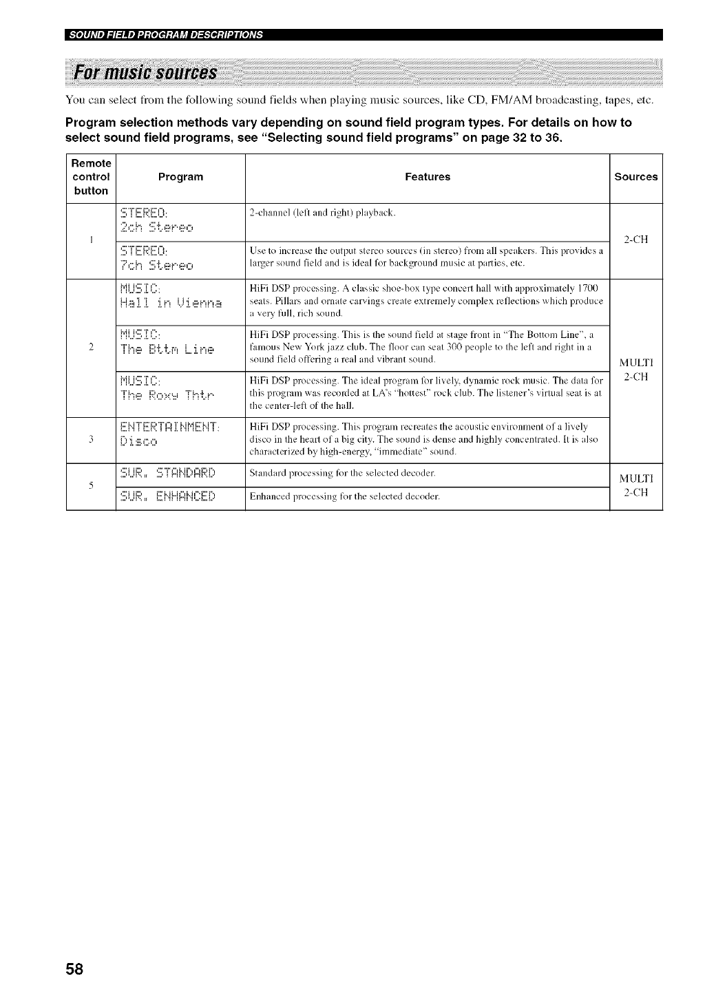
I_'_l]lJ_Vil_l=lllll:J:[lIel:L, Ij_ll]_.'fe_:ll:41[i]_v_
You can select from the following sound fiekts when playing music sources, like CD, FM/AM broadcasting, tapes, etc.
Program selection methods vary depending on sound field program types. For details on how to
select sound field programs, see "Selecting sound field programs" on page 32 to 36.
Remote
control Program Features Sources
button
'.!!!:T[!![[._?.i!!!ill): 2-channel/loll aM right) playback.
2 ,:::.i,:!!!;i..,ii?i..,iii,,:::,
I 2-CH
*<!!!:TE Pj!!!III_I: Use to increase Ihe oulput slereo sources fill slereo) fiom all speakers. This provides a
*?C.i"i S'{A?PeO hnger sound field and is ideal for background music at parties, elc.
{"iU'.!!i]i L:: HiFi DSP processing. A classic shoe-box type concerl hall with approximately 17or)
i"[<:::l 'i ]'i i"I i.i 'i I:::,i"li"*I.:::l seals. Pillars uld ornale carvings creale extremely complex refleclions which produce
a very full, rich sound.
{"ii...i'.!!i]i L:: HiFi DSP processing. This is Ihe sound field at stage front in "The Bottom Lille", a
2 T{"KI? P,',Qi'.r,', [ 'i i.",,::a famous New York jazz club. The floor can seal 300 people to Ihe lefl and right ill a
sound field offering a real and vibrant sound. MULTI
{"ii..J'.!!i]i L:: HiFi DSP processing. The ideal program 127rlively, dynamic rock music. The dala for 2-CH
*']"{"i'll? i:;i'i%':.:%.i "i'{"i=i:..i '`< lllis program was recorded at LA's "holiest" rock club. The lislener's virlual seal is al
file cenlerqefl of Ihe halh
i....FIi:::'i"i"L%2F12:'"Fiu'I_I..I".II"'.I.1'11Ti..ii'di::Fi..H">11..i.1l. HiFi DSP processing. This program recreales the acouslic environlilenl of a lively
3 {) :i.:ii;*,ii;O disco ill Ihe hearl of a big city. The sound is dense and highly concenlrated. II is also
characterized by, high-energy "imlnediate" sound.
*:::'i ii:::' '::7"i%"1M r'**lu'li:::,i"., Standard processing It)r Ihe selected decoder.
....,,...,,.,=_ ....,_ _...,_.,,..**,..'.,v.._.. MULTI
5
....*:::'i"...q '><==i i:::, l...*l "<qi::_<i"i i"i F'H" i ¢"=i1::'i"'W'H ".''.... i....i...' Enhanced processin_ fOl the selected decoder. 2-CH
58
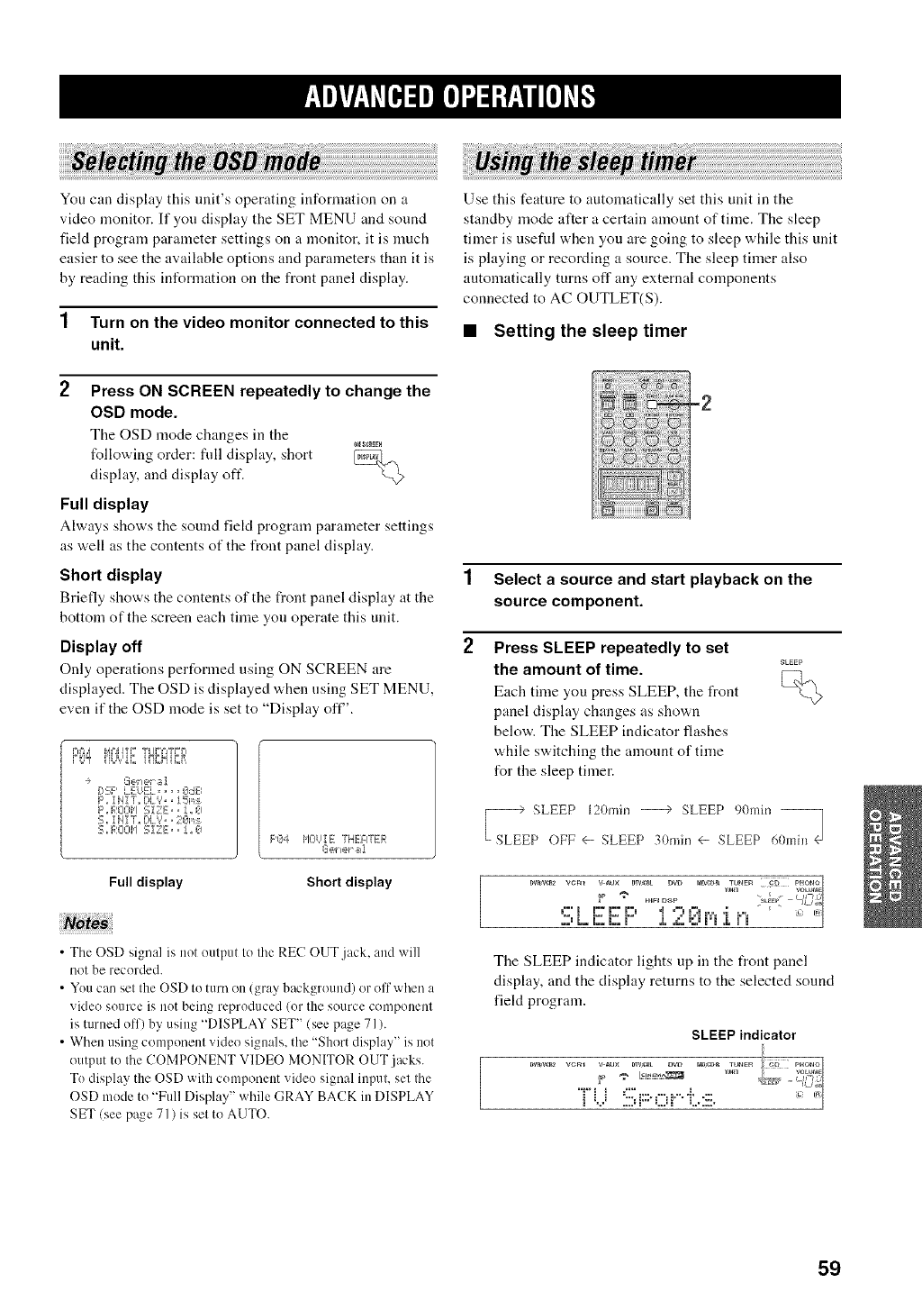
You can display this unit's operating information on a
video monitor. If you display the SET MENU and sound
field program parameter settings on a monitor, it is much
easier to see the available options and parameters than it is
by reading this information on the front panel display.
1 Turn on the video monitor connected to this
unit.
2Press ON SCREEN repeatedly to change the
OSD mode.
The OSD mode changes in the
following order: fldl display, short _,
display, and display off.
Full display
Always shows the sound fiekt program parameter settings
as well as the contents of the front panel display.
Short display
Briefly shows tire contents of the front panel disphty at the
bottom of the screen each time you operate this unit.
Display off
Only operations performed using ON SCREEN are
displayed. The OSD is displayed when using SET MENU,
even if the OSD mode is set to "Display off'.
G_@let _;1
[:,qF' L EL/EL .... 0dB
F'., 1HIT,, DL%, 15ns
F'.F,:CiOt,I :.=;iZE,, !,,0
5,, iHi"g_ [>k',',, 20n:_,
S,,F,,:OCII,ISIZE,, J,,O F'a4 HCiEE THE'aTL=R
Full display Short display
•The OSD signal is not output to the REC OUT.jack, and will
not be recorded.
•You can set the OSD to turn oi1 (gray background) or oll'when a
video source is not being reproduced (or the source component
is turned off) by using "DISPLAY SET" (see page 71).
• When using component video signals, the "Short display" is not
output to the COMPONENT VIDEO MONITOR OUT jacks.
To display the OSD with component video signal input, set the
OSD mode to "Full Display" while (;RAY BACK in DISPLAY
SET/see page 71 ) is set to AUTO.
Use this feature to automatically set this unit in the
standby mode after a certain amount of time. The sleep
timer is useful when you are going to sleep while this unit
is playing or recording a source. The sleep timer also
automatically turns off any external components
connected to AC OUTLET(S).
•Setting the sleep timer
-2
1 Select a source and start playback on the
source component.
2Press SLEEP repeatedly to set
the amount of time. _....
Each time you press SLEEP, the front _q._
panel display changes as shown
below. The SLEEP indicator flashes
while switching the amount of time
for the sleep timer.
SLEEP 120rain --> SLEEP 9()mhl
P OFF <- SLEEP 30rain <- SLEEP 60mhl
DVa'_R* VCm V _UX D_tC_t _VD mDcm_ IUHEg {g PHOnO
2;_L. E; i;; r= ,L ,,'; vj i_i ,Lr i
The SLEEP indicator lights up in the flout panel
display, and the display returns to the selected sound
fiekt program.
SLEEP indicator
_V_V_R2 TUN_5 VOLUM_
TU :!!i;F"Or.i:.:iii. -'°
59
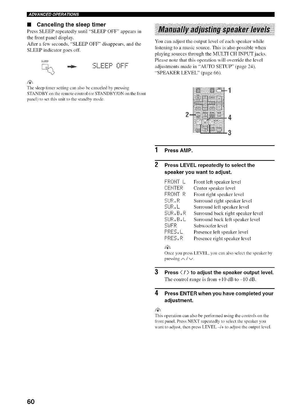
• Canceling the sleep timer
Press SLEEP repeatedly until "SLEEP OFF" appears in
the front panel display.
After a few seconds, "SLEEP OFF" disappears, and the
SLEEP indicator goes off.
_LEEP
The sleep timer setting can also be canceled by pressing
STANDBY on the remote control lot STANDBY/ON on the front
panel) to set this unit to the standby mode.
You can adjust the output level of each speaker while
listening to a nmsic source. This is also possible when
playing sources through the MULTI CH INPUT jacks.
Please note that this operation will override the level
adjustments made in "AUTO SETUP" (page 24),
"SPEAKER LEVEL" (page 66).
1 Press AMP.
2Press LEVEL repeatedly to select the
speaker you want to adjust.
l-:i:::HT i:::i:;?
_ii?i iiiii_ i
_?i iiiii_ ill) _111_
_ii?i iiiii_ ill) i
i_ iii_iiii__:ii_ i
iii_ iii_iiii__ii_ ill)
i i_,,_,_ _ _ i _,,
Front left speaker level
Center speaker level
Front right speaker level
Surround right speaker level
Surround left speaker level
Surround back right speaker level
Surround back left speaker level
Subwoofer level
Presence left speaker level
Presence right speaker level
Once you press LEVEL, you can also select the speaker by
pressing/x /v.
3 Press (/) to adjust the speaker output level.
The control range is from +10 dB to 10 dB.
4Press ENTER when you have completed your
adjustment.
_%,._
This operation can also be performed using the controls on the
front panel. Press NEXT repeatedly to select the speaker you
want to adjust, then press LEVEL /+ to a@lst the output level.
60
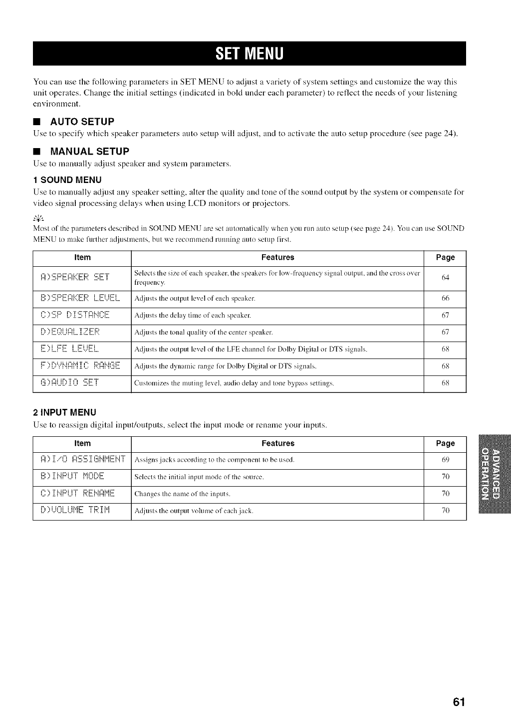
You cat] use the following paralneters in SET MENU to adjust a variety of system settings and customize the way this
unit operates. Change the initial settings (indicated in bokt under each paralneter) to reflect the needs of your listening
environlnent.
•AUTO SETUP
Use to specii_/which speaker parameters auto setup "a,ill adjllst, aud to activate the anto setup procedure (see page 24).
•MANUAL SETUP
Use to manually adjust speaker and system parameters.
1 SOUND MENU
Use to manually adjust any speaker setting, alter the quality and tone of the sound output by the system or compensate for
video signal processing delays when using LCD monitors or projectors.
Most of the parameters described in SOUND MENU are set automatically when you run auto setup (see page 24). You can use SOUND
MENU to make further adjustments, but we recommend running auto setup first.
Item Features Page
f"l ", ,:::'i:::,i::h"_i.."i:::'i:::, ,::'i:::'"F Selects tile size of each speaker, the speakers for low-frequency signal Otllptll, and Ihc cross over
frequency.
i:::,,, ,:::i:::,i::,",i...'i:::'i:::, i i:::'i ii:::'i ,A.(ljusts Ihe output level of each speaker. 66
*....P'.,,:::'i:::,.......,_i....i_'*'r ¢:' "r'€"dr"h"'i:::.L...'i r".q".'_....i.... A({jUSIS the delay tilne of each speaker. 67
i....r"".,...i... _.:.:,...,r".,i....i:::T'di ¢"_i Ta._:..."2i...i'..i::i:::, ,A.({jUst S Ihe tonal qualily of Ihe center speaker. 67
_,,,,."[,,,.li:::'"li i:::'i:::'i..,,i..,._....'."i..,.i..ii:::'iii:2i A({jtlsIS Ihe output level of Ihe LFE channelfor Dolby Digilal or DTS signals. 68
_"..'v"' '""""i i ".q".,_m"ia.,...._'"i'..r".".,....,...."",,..u..:_... A(ljusts Ihe dynamic range for Dolby Digital or DTS signals. 68
,..._..'m-...,v._.,..., ....,_...._ Customizes the muting level, audio delay and lone bypass settings. 68
2 INPUT MENU
Use to reassign digital input/outputs, select the input mode or renalne your inputs.
Item Features Page
I:::I::':[.."I'? I::4:!!!;:!!!;:[l:!_i'.ii"il!!!:i'.i"i"Assigns jacks according to the componcnl Io be used. 69
i:::,", Ti..ii:::q H" h'i¢"H%i::: '
_...,..'a.w. ,....i _........'_.... Selects the inilial inpul mode of the source. 70
f"", 'ri..ii:::q H" i:::,i:::'i..h"d.,_i:::'
_......'._.H_,...._ _'.._..,._'.,r".,.. Changeslhenalneoflheinputs. 70
1:::'::'i.)0[.,J..J{"[i!!:"i"[:;?.:[:["J Adjusls the oulput vohlme of eachjack. 70
61
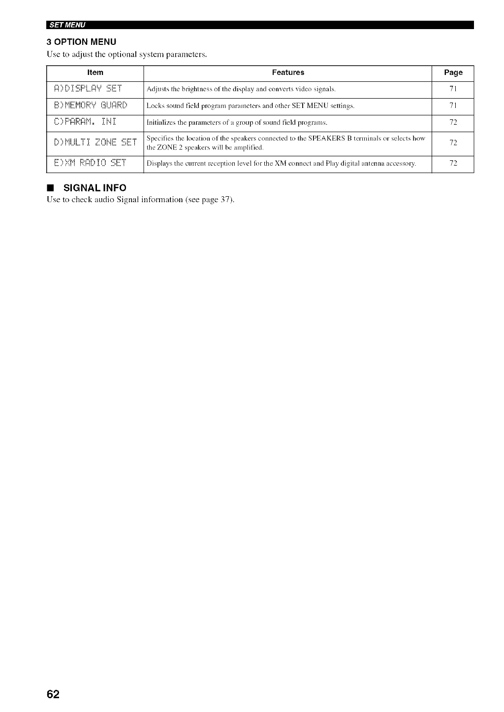
IF'l=lllJ_l_l'l,
3OPTION MENU
Use to adjust ttle optional system parameters.
Item Features Page
r'_t"l",...l....r"._.T...._i,::."i::)il...A...li"t_..ii...._i....,::."i:::'"i"_ Adjusls. Ihc bri_htncss_ of Ihc display and converts video si_nals._ 7 I
D ", Mi:::'i',4¢"H:::d.J ¢:.':i i_"lDi%
_...,..'_u...__,...._',_ ,..._,....r"u'.._.. Locks sound fMd program paran/clcrs and other SET MENU sellings. 7 ]
¢'= ", D ¢"H::) ¢"H',4 TMT
,......'_ r".,_',r".,__== ._._".,._. Initializes tile parameters of a group of sound field programs. 72
['?'?["[[[[ "F'[ ::::'I"I['._[:::''::_[:::'"["Specifies file location of Ihe speakers connected to Ihe SPEAKERS B terminals or selects how 72
.......................................... Ihe ZONE 2 speakers will be amplified.
[!!::''=:':==["i[:;;'.[::'4[)]:0 S[!!"F Displays the cl.lrrent reception le'_el lk)r tile XM connect and Play digilal antenna accessory. 72
•SIGNALINFO
Use to check audio Signal infornlation (see page 37).
62
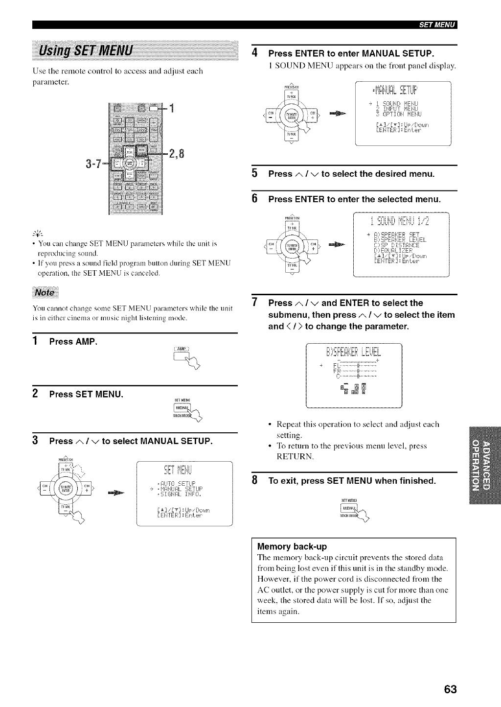
"l-'ill@_';'"
Use the remote control to access and adjust each
parameter.
{'il i_ii!
ii:!;!i i -z,8
3q-
i: i::i_;r'i!;!
iiiii!,¢!ii!i i!iii!:!iiiii!il
• Youcan change SET MENU parameters while the unit is
reproducing sound.
• If you press a sound field program button during SET MENU
operation, the SET MENU is canceled.
Press ENTER to enter MANUAL SETUP.
1 SOUND MENU appears on the l¥ont panel display.
A
"i ]Mi'gJN,o2:C,iUF
-+ ! SOLIHD HEHLI
2iHF'UT HEHLI
70F"[!OH HEHU
[_] r_]:Up [!o_,lh
[EHTER 2; E} d: e_
5 Press A/vto select the desired menu.
Press ENTER to enter the selected menu.
"\\
v
_%=IH_IFMI%IH 'i ,-"t
i,:,bLqk, i'["Li"[U *,"_,
÷ FI?5;F'EFIKER SET
B? SF'E'_KER LEUEL
C::,:-_;F'[' i 5;TF,14C:E
[,:,EOLIIqL!ZER
[_] g _] ;LIF 'DOk rl
r Ei4TER ] : E} d.et
You cannot change some SET MENU parameters while the unit
is in either cinema or music nighl lislening mode.
1 Press AMP.
Press SET MENU.
Press A/vto select MANUAL SETUP.
A
2'el l]i.i'iU
. AUTL-I E;E'rUF'
* "i'lgi4UIqL E;ETUF'
.51Gill€ iHFCi.
[ ElITEI_I] ;Erd: ek
Press A/vand ENTER to select the
submenu, then press A/vto select the item
and {/>to change the parameter.
8..'.2#C.H[,.C_.Li:;;'di;i..
-__ .... +
FL' ..............l!..............
FB .............4i..............
_Z NN
•Repeat this operation to select and adjust each
setting.
• To return to the previous menu level, press
RETURN.
8 To exit, press SET MENU when finished.
Memory back-up
The memory back-up circuit prevents the stored data
from being lost even if this unit is in the standby mode.
However, if the power cord is disconnected from the
AC ontlet, or the power snpply is cut for more than one
week, the stored data will be lost. If so, adjnst the
items again.
63
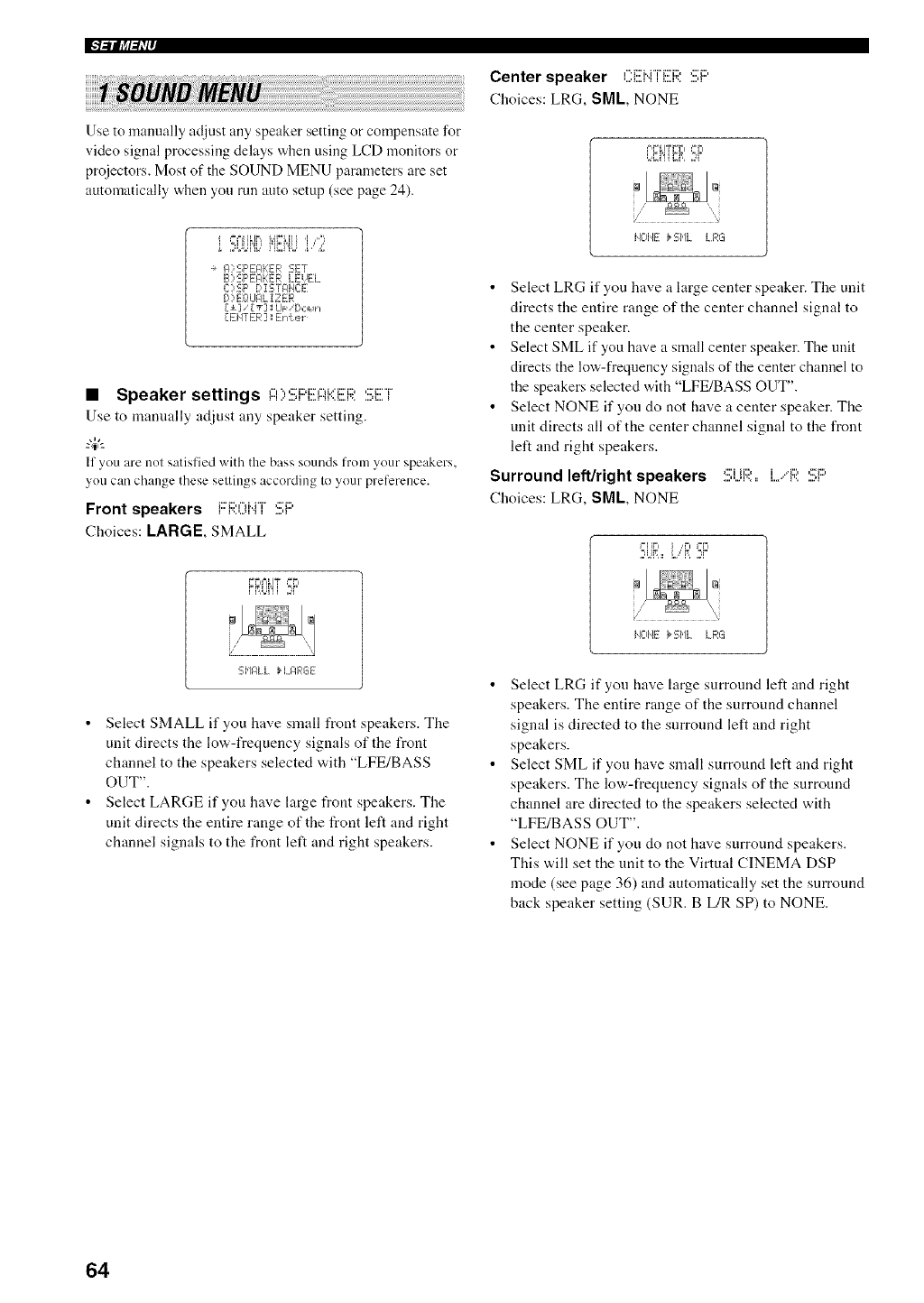
IFl_lljff_II'
Use to manually ac!iust any speaker setting or compensate for
video signal processing delays when using LCD monitors or
projectors. Most of the SOUND MENU parameters are set
automatically when you rnn auto setup (see page 24).
2U°IT' i'i",i'iUb'/.
÷ _):_;F'E]_KER 'sE:r
B):-]F'EF]KER LEVEL
C:,:_;F' D !:-;TFI'E:E
D)EOLIPL IZER
Ill [_] ILIF/[!outl
[EiITER] EIA.el
•Speaker settings A):!!;F::i!![I::ii:::EF;;:SET
Use to manually adjust any speaker setting.
W--
if you are not satisfied with the bass sounds from your speakers,
you can change these settings according to your prel'erence,
Front speakers F'RONT SP
Choices: LARGE, SMALL
FFH% IT _=F=
FRUI'Ii ,W
SHF;LL H. FE,:GE
• Select SMALL if you have small front speakers. The
unit directs the low-frequency signals of the front
channel to the speakers selected with "LFE/BASS
OUT".
• Select LARGE if you have large front speakers. The
unit directs the entire range of the front left and right
channel signals to the front left and right speakers.
Center speaker f"i:::'HTi:::'i:::,,:::'lid
Choices: LRG, SML, NONE
F,FIITFFI _=Fi
bCi'iiii, ,W
Z • 2_I
ilO]IE _Si,IL LRG
• Select LRG if you have a large center speaker. The unit
directs the entire range of the center channel signal to
the center speaker.
•Select SML if you have a small center speaker. The unit
directs the low-frequency signals of the center channel to
the speakers selected with "LFE/BASS OUT".
• Select NONE if you do not have a center speaker. The
unit directs all of the center channel signal to the front
left and right speakers.
Surround left/right speakers :!!!;ijF;;::: L/R SF:'
Choices: LRG, SML, NONE
I=IIFI ] ,,FI I=FI
,°,,=,:,,=:=,:,,,::F
IIL-IHE i_51,1L LF,:G
•Select LRG if you have large surround left and right
speakers. The entire range of the surround channel
signal is directed to the surround left and right
speakers.
• Select SML if you have small surround left and right
speakers. The low-frequency signals of the surround
channel are directed to the speakers selected with
"LFE/BASS OUT".
• Select NONE if you do not have surround speakers.
This will set the unit to the Virtual CINEMA DSP
mode (see page 36) and automatically set the surround
back speaker setting (SUR. B L/R SP) to NONE.
64

Surround back speakers ,:::_H:::, i::,i ..._:::,_::.i:::,
Choices: LRGxl, LRGx2, SMLx2, SMLxl, NONE
k=iiC' r,i .,r, =°r,
/
SHL:::i _ E;HL:::2
)
Select LRGxl if you have a large surround back
speaker. The unit directs the entire range of the
snrround back channel signal to the left surronnd back
speaker.
Select LRGx2 if you have 2 large surround back
speakers. The unit directs the entire range of the
surround back channel signal to the surround back
speakers.
Select SMLx2 if you have 2 small surround back
speakers. The low-frequency signals of the surround
back channels are directed to the speakers selected with
"LFE/BASS OUT"
Select SMLxl if you have a small surround back
speaker. The low-frequency signals of the surround
back channel are directed to the speakers selected with
"LFE/BASS OUT", and the rest of the t_equency
signals are directed to the left surround back speaker.
Select NONE if you do not have a surround back
speaker. The unit directs all of the surround back
channel signal to the surround left and right speakers.
If you select SMLx I or LRGx 1.connect the speaker to the left
SURROUND BACK speaker terminals.
Presence speakers i:::'i:;;:E:!!!;i!!!HCi!!!:!!!;i::'
Choices: YES, NONE
k_k_kk g},i ,g =H
i i"&=k,i%'i= ,I_F
• Select YES if you have presence speakers.
• Select NONE if yon do not have presence speakers.
W--
WhenYES is selected, the unit automatically a_({uststhe dialog
lilt parameter. To ac0ustit manually, see page 92.
I-ilJ_I-_W"
Bass out i...l:::E,"i!!:l::i:!!;:!!!;OijT
Lo'a,-frequency (bass) signals can be directed to the
subwoofer and/or the front left and right speakers
according to the characteristics of your system. This
setting also determines the routing of the LFE (low-
frequency effect) signals found in Dolby Digital or DTS
sonrces.
Choices: SWFR, FRNT, BOTH
5,ilFR FRJIY}_El._JYH
• Select SWFR if you connect a subwoofer. LFE and
low-frequency signals from other channels are directed
to the subwoofer according to the speaker settings.
• Select FRNT if you do not use a subwoofer. LFE and
low frequency signals from other channels are directed
to the front speakers according to the speaker settings
(even if yon have previously set front speakers to
SML).
• Select BOTH if you connect a subwoofer and yon want
to output low-frequency signals from front channels to
both the front speakers and subwoofer. LFE and low-
frequency signals from other channels are also directed
to the subwoofer according to the speaker settings. Use
this function to reinforce low-frequency signals using
the subwoofer when playing back sources such as CDs.
Cross over Ci:;;'.0:!!;S0i.)Ei:i:
Use this feature to select a cross-over (cut-off) frequency
for all low-frequency signals. All frequencies below the
selected frequency will be sent to the subwoofer.
Choices: 40Hz, 60Hz, 80Hz, 90Hz, 100Hz, l l0Hz,
120Hz, 160Hz, 200Hz
C:i:0);1-;,,'1",,*o'7:
65
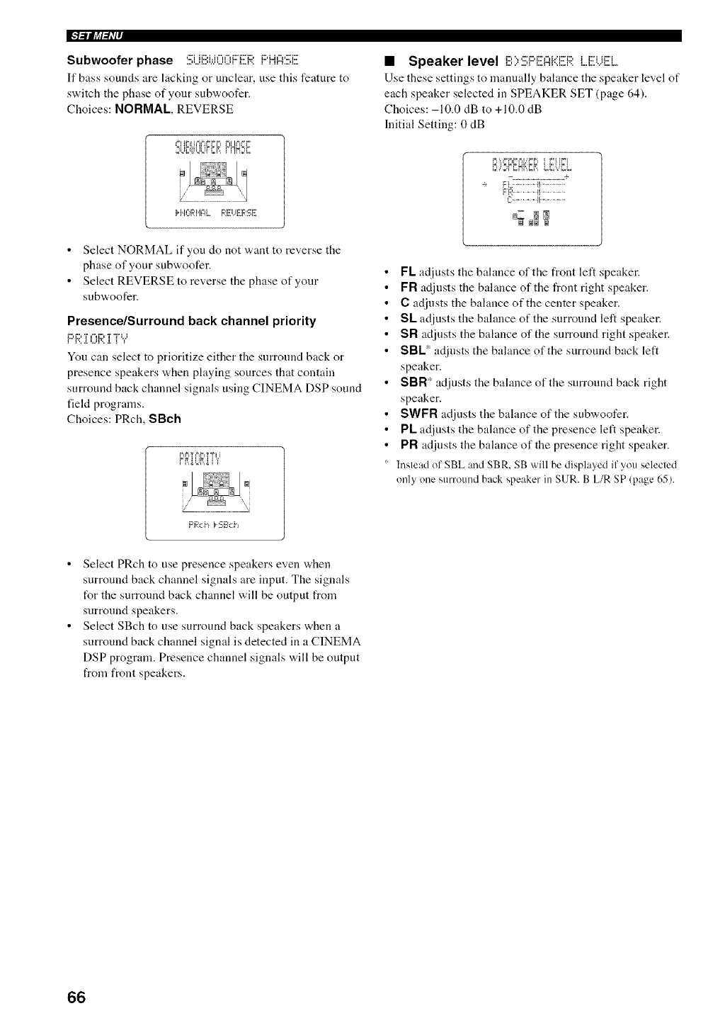
IFl_lljg_IL'
Subwoofer phase SU{!!!IW()()FEi:;I:FI'HASF
If bass sounds are lacking or unclear, use this featnre to
switch the phase of your sub'a, oofer.
Choices: NORMAl, REVERSE
q i;li,li=i{=i,=;;,m,,=,,-.,=
H_C RI'IglL REUERSE
• Select NORMAL if you do not want to reverse the
phase of your subwoofer.
• Select REVERSE to reverse the phase of your
subwoofer.
Presence/Surround back channel priority
F'R i[OR i T"?
You can select to prioritize either the surround back or
presence speakers when playing sources that contain
surround back channel signals using CINEMA DSP sound
field programs.
Choices: PRch, SBch
Pg'TFlg'TTL,'
F'geci_ _,5;EIch
•Speaker level i!!!:;,:!!;i:::'EI:::Ii::Zi!!!F;;:LEUEi.
Use these settings to manually bahmce the speaker level of
each speaker selected in SPEAKER SET (page 64).
Choices: -10.0 dB to +10.0 dB
Initial Setting: 0 dB
'.=,',,l%=,f=J=,U'.=".=' i f"l H"I
8)2#CHh,E,_,i.J:LViE..
-._ ........................ ,+
FL' ..............[i..............
FR....... I_........
L-:.......... li ..........
_Z NN
@_NN
FL adjusts the balance of the front left speaker.
FR adjnsts the balance of the front right speaker.
Cadjusts the balance of the center speaker.
SL adjusts the balance of the surround left speaker.
SR adjusts the balance of the surround right speaker.
SBL* adjnsts the balance of the surround back left
speaker.
SBR* adjusts the balance of the surround back right
speaker.
SWFR adjusts the balance of the subwoofer.
PL adjnsts the balance of the presence left speaker.
PR adjusts the balance of the presence right speaker.
Instead of SBL and SBR, SB will be displayed if you selected
only one surround back speaker in SUR. B L/R SP (page 65).
• Select PRch to use presence speakers even when
surround back channel signals are input. The signals
t_r the surround back channel will be output from
surround speakers.
• Select SBch to use surround back speakers when a
surround back channel signal is detected in a CINEMA
DSP program. Presence channel signals will be output
from front speakers.
66
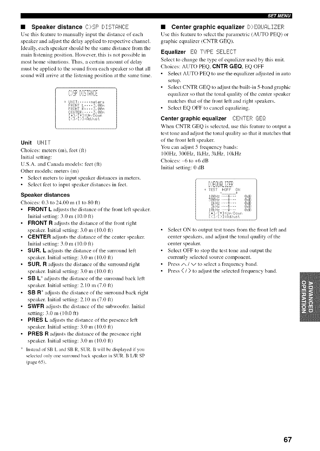
•Speaker distance O)SF:'D]IS[I:::Iii(?i!!!
Use this feature to manually input the distance of each
speaker and adjust the delay applied to respective channel.
Ideally, each speaker should be the same distance from the
main listening position. However, this is not possible in
most home situations. Thus, a certain anaonnt of delay
nmst be applied to the sound from each speaker so that all
sound will arrive at the listening position at the same time.
P'", _=L_ R ?_=%%lP'F'
o..Di i.."DiN'iL.r.
UHiT ..... ne_.el ::_
FROH7 L,,., 3,, 07_m
FRCIHT R 3. OOl'_
C:EHTER..... :L, Onl,_
[{ ] '[ ) ] IT4dj:,lSt
Unit i Ji.i]/T
Choices: meters (m), feet (tt)
Initial setting:
U.S.A. and Canada models: feet (it)
Other models: meters (m)
• Select meters to input speaker distances in meters.
• Select feet to input speaker distances in feet.
Speaker distances
Choices: 0.3 to 24.00 m(1 to 80 it)
FRONT L adjuststhe distance of the front left speaker.
Initial setting: 3.0 m (10.0 ft)
FRONT R adjusts the distance of the front right
speaker. Initial setting: 3.0 m (10.0 ft)
CENTER adjusts the distance of the center speaker.
Initial setting: 3.0 m (10.0 ft)
SUR. L adjusts the distance of the surround left
speaker. Initial setting: 3.0 m (10.0 ft)
SUR. R adjusts the distance of the surround right
speaker. Initial setting: 3.0 m (10.0 ft)
SB L* adjusts the distance of the surround back left
speaker. Initial setting: 2.10 m (7.0 ft)
SB R* adjusts the distance of the surround back right
speaker. Initial setting: 2.10 m (7.0 ft)
SWFR adjusts the distance of the subw,'oofer. Initial
setting: 3.0 m (10.0 ft)
PRES L adjusts the distance of the presence left
speaker. Initial setting: 3.0 m (10.0 ft)
PRES R adjusts the distance of the presence right
speaker. Initial setting: 3.0 m (10.0 ft)
Instead ofSB L and SB R. SUR. B will be displayed if you
selecled only one surround back speaker in SUR. B L/R SP
(page 65).
l-!lig-_i';""
•Center graphic equalizer F',",i:::'l"iiil"li T"::ii::['i::)
L.<:' L...,.:.:,..,r"l L...L =:..L..r.<
Use this feature to select the parametric (AUTO PEQ) or
graphic equalizer (CNTR GEQ).
Equalizer _:::,-,"r,.u:::,_::,:::_:::__:::,-."_
Select to change the type of equalizer used by this unit.
Choices: AUTO PEQ, CNTR GEO, EQ OFF
• Select AUTO PEQ to use the equalizer adjusted in auto
setup.
• Select CNTR GEQ to adjust the built-in 5-band graphic
equalizer so that the tonal quality of the center speaker
matches that of the front left and right speakers.
• Select EQ OFF to cancel equalizing.
Center graphic equalizer , m.mcD ,:::_:::,-,
When CNTR GEQ is selected, use this feature to output a
test tone and adjust the tonal quality so that it matches that
of the front left speaker.
You can adjust 5 frequency bands:
100Hz, 300Hz, lkHz, 3kHz, 10kHz
Choices: -6 to +6 dB
Initial setting: 0 dB
,",,',,,"=PJlh°il ?gFFi
W,,'U:,LJ'ffLb'A',D?,,
T [':T;'T bCIFF 014
-. ............. +
D_iF_FIT:' '" Ib........ Fide
700Hz '"1_ ........ 1_,:TE
!kilT: ,, , II .... OdE=
3i<Hz '"It ....... 1752_El
101::Hz ""ii ........ E',NEi
F_] [_'] UF ['.: ,n
[ ;] ] *[ ] ] _d,J !1$ i1
•Select ON to output test tones from the front left and
center speakers, and adjust the tonal quality of the
center speaker.
• Select OFF to stop the test tone and output the
currently selected source component.
• Press/x /v to select a frequency band.
• Press < / ) to adjust the selected frequency band.
67
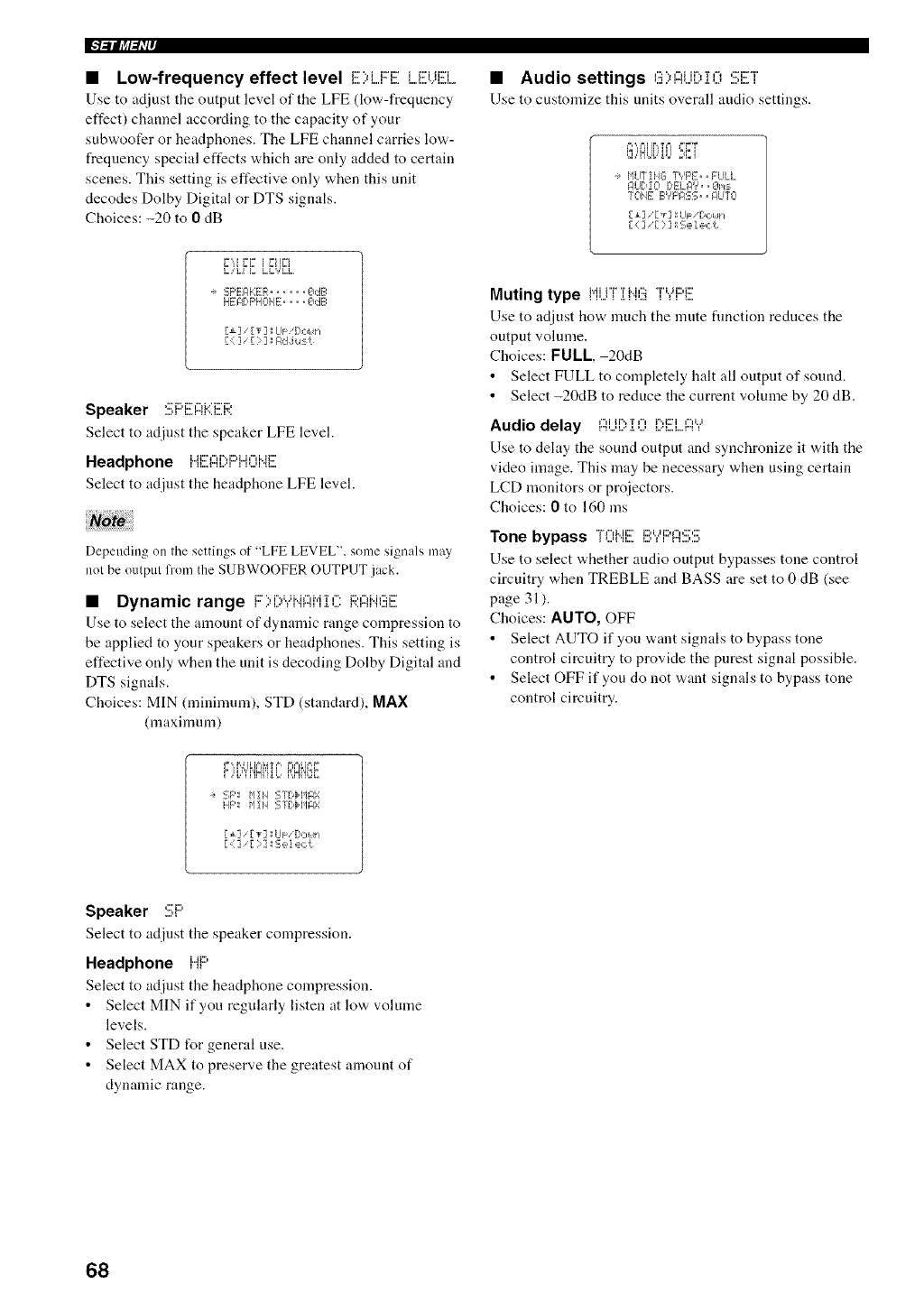
Use to adjust the output level of the LFE (low-frequency
effect) channel according to the capacity of your
subwoofer or headphones. The LFE channel carries low-
frequency special effects which are only added to certain
scenes. This setting is effective only when this unit
decodes Dolby Digital or DTS signals.
Choices: -20 to 0dB
Low-frequency effect level ,.....,,....,_:::"_ m:::,..._...,.........,...,__:::.i_i:::i.... • Audio settings ,..,"::'",""_.,,.._,..,,....'",.r,-,.,.,...,....,,...':::i:::"r',
Use to customize this units overall audio settings.
i, ,,111 i1,, ii =_FI
qhl.i: __J =,o=,._,
i,ILITI HG TYF'E..FLILL
g_UDI0 DE:LAV., ZIres
TOHE EVF'A::5::_,•ALITO
[ i] /_r_<] I LI_: ,[!ov_,
[::] [: ]ISelect
F',,I FF i FIIFI
I=,,i=,i I_ I°,I_','I_,
SF'EAHER ...... OcIE;
HEA[)F'HOI4E.... O,:_E=
r<_] Iv] LII=["it li
[ : ] [ : ] IAd J u::._t
Speaker :!!!;F:'i!![l::?i:::i!!!]:;;'.
Select to adjust the speaker LFE level.
Headphone i"41!!):::IDi:::'HOi"41!!!:
Select to adjust the headphone LFE level.
Depending on II'le settings of "LFE LEVEL", some signals may
nol be output from the SUBWOOFER OUTPUT jack.
•Dynamic range F)i:Y?ifiAM:1C i:;tl:ii".i(!!ii!!!
Use to select the amount of dynamic range compression to
be applied to your speakers or headphones. This setting is
effective only when the unit is decoding Dolby Digital and
DTS signals.
Choices: MIN (minimum), STD (standard), MAX
(maximum)
Muting type i"ii..j"i"i i".i(!i"i"","i:::'i:::'
Use to adjust how much the mute fimction reduces the
output volume.
Choices: FULL, 20dB
•Select FULL to completely halt all output of sound.
• Select -20dB to reduce the current volume by 20 dB.
Audio delay I:::Ii.jD:i:O i]:,i!!!]...l::i?
Use to delay the SOtll:ld output and synchronize it with the
video image. This may be necessary when using certain
LCD monitors or proiectors.
Choices: 0to 160 ins
Tone bypass [OHi!!! £!:"?i:::'ASS
Use to select whether audio output bypasses tone control
circuitry when TREBLE and BASS are set to 0 dB (see
page 31 ).
Choices: AUTO, OFF
• Select AUTO if you want signals to bypass tone
control circuitry to provide the purest signal possible.
• Select OFF if you do not want signals to bypass tone
control circuitry.
SF'I f'lIi4 S'T[:+HAX
HF' ['1Ii4 ST[:,i,I'IA:7
r_] [_] LF[,,:,n
[,:1]<[ 1] 1-1,_,]e,:I:
Speaker :!!!;F:'
Select to adjust the speaker compression.
Headphone Hi:::'
Select to adjust the headphone compression.
• Select MIN if you regularly listen at low volume
levels.
• Select STD for general use.
• Select MAX to preserve the greatest amount of
dynamic range.
68
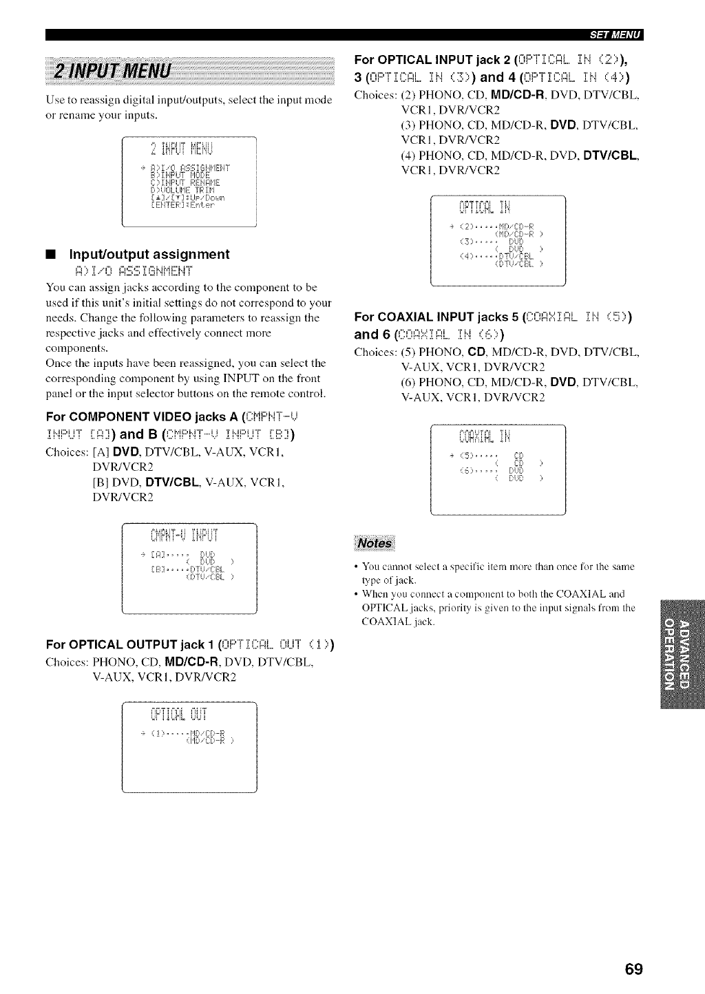
Use to reassign digital input/outputs, select the input mode
or rename your inputs.
,=_ TLIP_IIT bIP_HI
£ _i'£LH ]'iE,HU
a R)I/O F,S:_;I6HI'IE:i4r
B) ZNF'UT HCIDE
C?iHF'UT REHFIHE
D)UOL LIIqE TRIH
[£] 'Iv] ; UF/DCIUh
[ E:HTER] _EhLe_
•Input/output assignment
I:'_':_T..."I')i::l'::_C::Tl':_b@'ii:::'b_T
You can assign jacks according to the component to be
used if this unit's initial settings do not correspond to your
needs. Change the follow'ing parameters to reassign the
respective jacks and effectively connect more
components.
Once the inputs have been reassigned, you can select the
corresponding component by using INPUT on the t}ont
panel or the input selector buttons on the remote control.
For COMPONENT VIDEO jacks A (CJ"IF'NT-i.)
]:I"/F::'UT [: I:::I]) and B (C:J"IF::'NT-k.i :[l.lj:::'i...il [: B ])
Choices: [A] DVD, DTV/CBL, V-AUX, VCRI,
DVR/VCR2
[B] DVD, DTV/CBL, V-AUX, VCRI,
DVR/VCR2
I-'/I/@_W"
For OPTICAL INPUT jack 2 (0F:'Ti(..:FIL ]:l'q (2)),
3 (OF::'T]: (.'.L'IZil..,.]: J".l (3)) and 4 (OF'T:[(:::FIL ]:J".l (4))
Choices: (2) PHONO, CD, MD/CD-R, DVD, DTV/CBL,
VCRI, DVR/VCR2
(3) PHONO, CD, MD/CD-R, DVD, DTV/CBL,
VCRI, DVR/VCR2
(4) PHONO, CD, MD/CD-R, DVD, DTV/CBL,
VCRI, DVR/VCR2
P_rhTtP,_I 'rH
LiP i _o,ML "i"i
a (2) ..... ['_D'CD'-R
(HD 'CD'-R )
(3) ..... DUD
( DUD )
(4) ..... DTUiCE:L
(DTUiCBL)
For COAXIAL INPUT jacks 5 (COFIN:[I:?[... :[J".l (5))
and 6 (COAX:i:I:::Ii....:i:i.i ,::6 ))
Choices: (5) PHONO, CD, MD/CD-R, DVD, DTV/CBL,
V-AUX, VCR 1, DVR/VCR2
(6) PHONO, CD, MD/CD-R, DVD, DTV/CBL,
V-AUX, VCR 1, DVR/VCR2
P,_.=iU T_=i '1%[
L,L]H_"4N,. "i"i
÷ (5) ..... CD
< CD )
(6) ..... DUD
( DUD )
L,i]i i']i=',, ,' "i"ii"Ui
[A] ..... DUD
( DUD )
[ B] ..... DTUiCBL
( DTUiC:E:L )
For OPTICAL OUTPUT jack I (0F'T :[CI::?L OUT (:l.))
Choices: PHONO, CD, MD/CD-R, DVD, DTV/CBL,
V-AUX, VCRI, DVR/VCR2
•You cannot select a specific item more than once for the same
type of jack.
• When you connect a component to both the COAXIAL and
OPTICAL .jacks, priority is given to the input signals from the
COAXIAL jack.
,1 _..... HD CD'-R
(HD L2D-R :
69
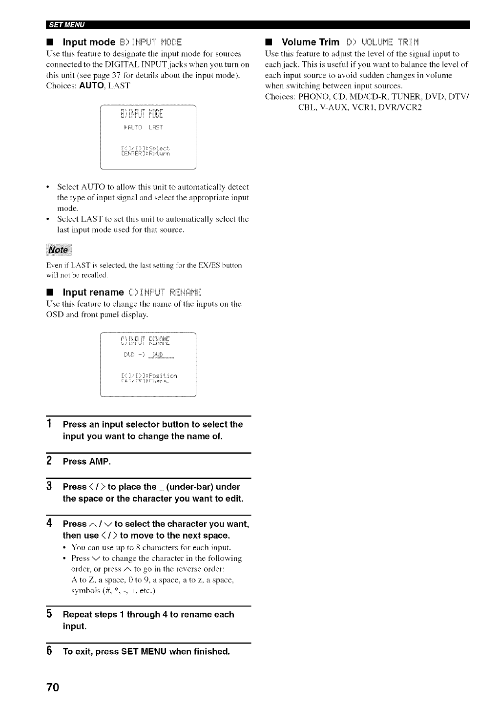
• Input mode B;,;i;iqi:::'i...ii' MOi;,E
Use this feature to designate tile input mode for sources
connected to the DIGITAL INPUT .jacks when you turn on
this unit (see page 37 for details about the input mode).
Choices: AUTO, LAST
ii,, l_lklil _1_1ii,,i
k _t.IyO I_F,'ST
[ _]] [ i: ] ; Se ] ect
[Ei4TEI-_I] Rett4_ h
•Volume Trim [:,> i...U3i....UMi!!['ii:;i'.i[i"i
Use this feature to adjust the level of'the signal input to
each jack. This is useful if you want to bahmce the level of"
each input source to avoid sudden changes in volume
when switching between input sources.
Choices: PHONO, CD, MD/CD-R, TUNER, DVD, DTV/
CBL, V-AUX, VCR 1, DVR/VCR2
• Select AUTO to allow this unit to automatically detect
the type of input signal and select the appropriate input
mode.
• Select LAST to set this unit to automatically select the
last input mode used for that source.
Even if LAST is selected, the last setting for the EX/ES button
will not be recalled.
•Input rename ', 'i'Mi::HH" i:::d:::'i..h-lh.ii:::'_...i.I. HI I.jI I'><l...I_r'_IIl ....
Use this feature to change the name of the inputs on the
OSD and front panel display.
.r:i] [? ] F'o:_ition
It] Fv]lL-i_,r:,,,
1 Press an input selector button to select the
input you want to change the name of.
2Press AMP.
3 Press </>to place the _(under-bar) under
the space or the character you want to edit.
4Press .,_/ vto select the character you want,
then use < />to move to the next space.
• You can use up to 8 characters for each input.
• Press v to change the character in the following
order, or press/x to go in the reverse order:
A to Z, a space, 0 to 9, a space, a to z, a space,
symbols (#, *, -, +, etc.)
5 Repeat steps 1 through 4 to rename each
input.
6To exit, press SET MENU when finished.
7O
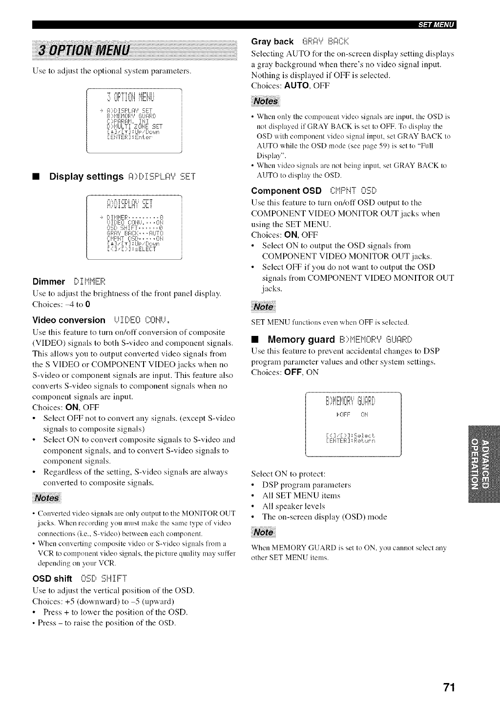
Use to adjust the optional system parameters.
"Y P_r_,,=%%iMr%HI
0 L¢ iUJi'i i'i",i'iU
F4?g,,!5F'LJ:I9SET
B?HEI'IOR'? GUARD
L2;'F'ARF, H,, !H!
['?HULT! 20I'IE 5ET
[±] 'IT] ; LIp Dok,_1
[ EH'/EF ] :' En<_.e_
• Display settings ,",'.,rvr,:::'i:::,i,",,..,,::=::"T'
Pl",F',Tl=rJl ffIH _'_
H..'i.."2¢L_'i 2_ i
DII@IER ......... @
U!DE:O CClHU. ,, ,OH
O'_D €:H! FT ...... g
GRI:I'J EIF£:K,, ,PLITCI
C:HF'iQ 0'3D ...... OH
[ ±] '[_] ; kl_: '[!ouh
[ < ] '[ :] sE:LEC:T
Dimmer r.,TMMi:::i:::,
i,,,",i, 1 H H,,,A',,
Use to adjust the brightness of the front panel display.
Choices: _ to 0
Video conversion i i'ri".,i:::',"li".,-H..iii
Use this feature to turn on/off conversion of composite
(VIDEO) signals to both S-video and component signals.
This allows you to output converted video signals from
the S VIDEO or COMPONENT VIDEO jacks when no
S-video or component signals are input. This feature also
converts S-video signals to component signals when no
component signals are input.
Choices: ON, OFF
• Select OFF not to convert any signals. (except S-video
signals to composite signals)
• Select ON to convert composite signals to S-video and
component signals, and to convert S-video signals to
component signals.
• Regardless of the setting, S-video signals are always
converted to composite signals.
• (X n erred vide( sienals are only output lu the MONITOR OUT
jacks. When recurding you musl make Ihe same type of video
cunueclions (i.e.. S-video) between each component.
•When cou',ertiug cumposile video or S-video signals frum a
VCR to cumpuuenl videu signals, the picture quality may suffer
depending on your VCR.
OSD shift ,-,c'r'., ,:::'i...iTi::?i
Use to adjust the vertical position of the OSD.
Choices: +5 (downward)to-5 (upward)
• Press + to lower the position of the OSD.
• Press to raise the position of the OSD.
l-'llllff-_W"
Gray back ,':::m,-,,..,i:::,,-,,-._..'
Selecting AUTO for the on-screen display setting displays
a gray background when there's no video signal input.
Nothing is displayed if OFF is selected.
Choices: AUTO, OFF
•When uuly the compuueul vMeo signals are input, the OSD is
not displayed if GRAY BACK is set Io OFF. To display the
OSD with cumponent videu signal input, sel GRAY BACK lu
AUTO while Ihe OSD mude/see page 59) is sel to "Full
Display".
• When _ideu signals are not being inpul, set GRAY BACK Io
AUTO tu display the OSD.
Component OSD ,".i.,_i=,M"r',",,:::'r'.,
Use this feature to turn on/off OSD output to the
COMPONENT VIDEO MONITOR OUT jacks when
using the SET MENU.
Choices: ON, OFF
•Select ON to output the OSD signals from
COMPONENT VIDEO MONITOR OUT jacks.
• Select OFF if you do not want to output the OSD
signals from COMPONENT VIDEO MONITOR OUT
jacks.
SET MENU funcliuns exert when OFF is selecled.
•Memory guard BI:,NEHOR"?(!_i.ji::lj:;i:[)
Use this feature to prevent accidental changes to DSP
program parameter values and other system settings.
Choices: OF[ = , ON
_l,,_ L}_I I 'l I]l_ I]',
_OFF OH
[ :::] [ : ]aSe!e,:t
[EHTER] Re{u_ n
Select ON to protect:
• DSP program parameters
• All SET MENU items
• All speaker levels
• The on-screen display (OSD) mode
When MEMORY GUARD is set lu ON, you cannot selecl any
other SET MENU items.
71
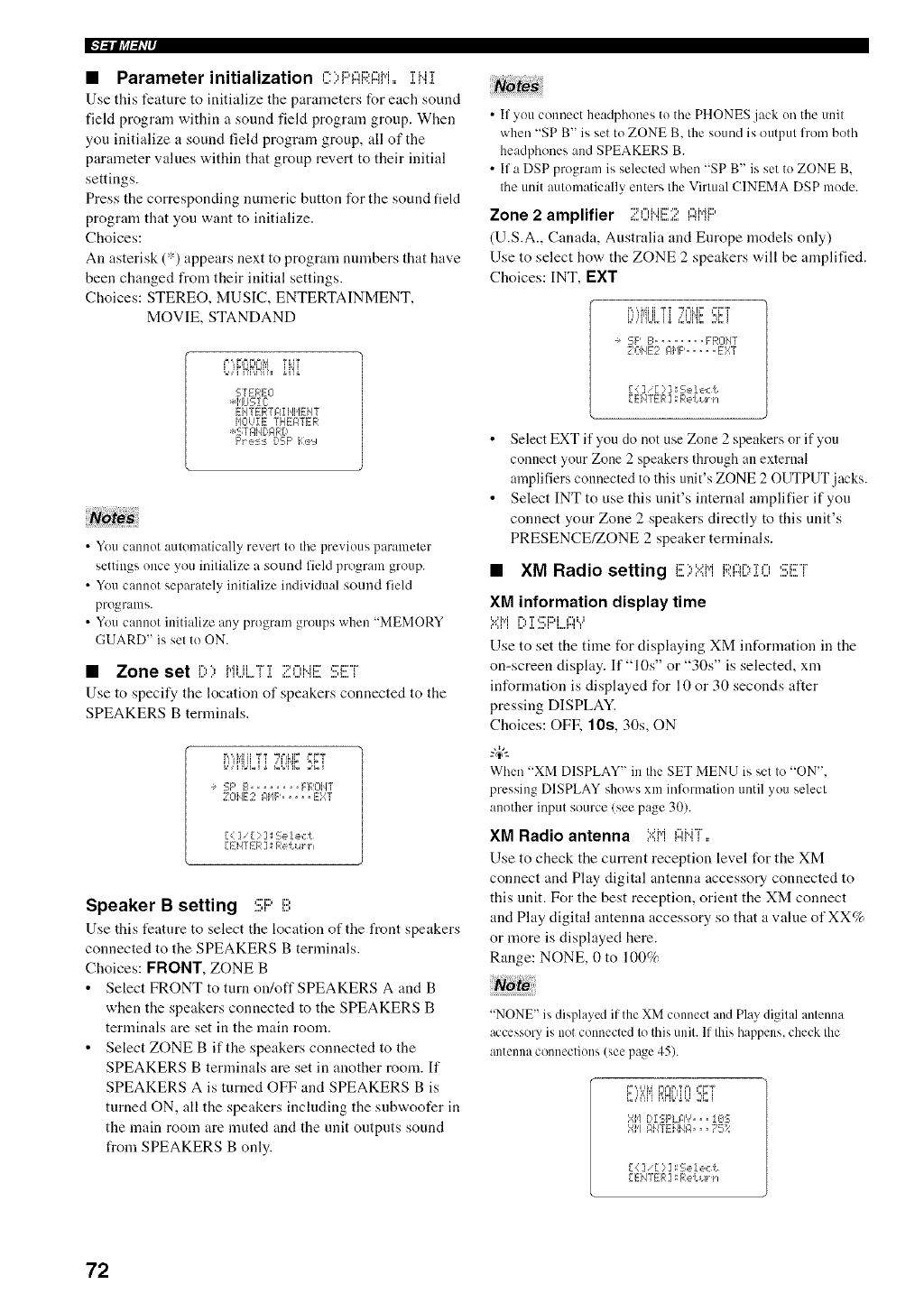
IFl_lljff_IP
•Parameter initialization C:;d:::";:IF;;:PM.iH]i
Use this feature to initialize the parameters for each sound
fiekt program within a sound field program group, When
you initialize a sound field program group, all of the
parameter values within that group revert to their initial
settings.
Press the corresponding numeric button for the sound field
program that you want to initialize.
Choices:
An asterisk (*) appears next to program numbers that have
been changed from their initial settings.
Choices: STEREO, MUSIC, ENTERTAINMENT,
MOVIE, STANDAND
,=,.r:,r,:,M Ti,iT
STEREO
*HUS!C:
EHTER? _,!NI_IEHT
HOUiE THE_,TER
*STAIq[ I:IRD
F'res:_ DSF' i<:e':l
• You cannot automatically revert to the previous parameter
settings once you initialize a sound field program group.
• Yon cannot separately initialize individual sound field
programs.
• You cannot initialize any program groups when "MEMORY
GUARD" is set to ON.
•Zone set r,', i.,.ii ii "i" T "::h",Mi::" (::'i:::'"i"
Use to specify the location of speakers connected to the
SPEAKERS B terminals.
r..',i.#iiYt _PiHF' ==i_,,_
i..')iibLi t.'LUi'i_.:_ i
e SF' B ........ FFqOMT
,_L, ,. z n,h. .... EXT
[.:::2'r : ] _Se !ect
[E}4TER ] : F<e'u.4rh
Speaker B setting SF:'B
Use this feature to select the location of the front speakers
connected to the SPEAKERS B terminals.
Choices: FRONT, ZONE B
• Select FRONT to turn on/off SPEAKERS A and B
when the speakers connected to the SPEAKERS B
terminals are set in the main room.
• Select ZONE B if the speakers connected to the
SPEAKERS B terminals are set in another morn. If
SPEAKERS A is turned OFF and SPEAKERS B is
turned ON, all the speakers including the subwoofer in
the main room are muted and the unit outputs sound
from SPEAKERS B only.
• If you connect headphones to the PHONES jack on the unit
when "SP B" is set to ZONE B. the sound is output from both
headphones and SPEAKERS B.
• If a DSP program is selected when "SP B" is set to ZONE B.
the unit automatically enters the Virtual CINEMA DSP mode.
Zone 2 amplifier Z.0Hi!![:;?.l::ii"ii:::'
(U.S.A., Canada, Australia and Europe models only)
Use to select how the ZONE 2 speakers will be amplified.
Choices: INT, I=XT
°r. _,°,ur ,=for
i.Ui'iHl.........H UJi'i'.:.2'.:i
e SF' B ........ FR0iqT
Z014E2 _I'IF', .... E::::T
{ :] {: ]:Se!e,:L
[EHTER] Re{ut h
• Select EXT if you do not use Zone 2 speakers or if you
connect your Zone 2 speakers through an external
amplifiers connected to this unit's ZONE 2 OUTPUT jacks.
• Select INT to use this unit's internal amplifier if you
connect your Zone 2 speakers directly to this unit's
PRESENCE/ZONE 2 speaker tenninals.
•XM Radio setting i:::.,,..,_,ii:::,,',rvr,,c:i:::r
I..."¢'4 I I"A",q..'%LU ...q.,,
XM information display time
=...q','i r% T (::'i:::d i"O..i
I'M I I,,=" ,I, ,,,,11 l,,,,r"l 1
Use to set the time for displaying XM information in the
on-screen display. If "10s" or "30s" is selected, xm
information is displayed for 10 or 30 seconds alter
pressing DISPLAY.
Choices: OFK 10s, 30s, ON
-#.
When "XM DISPLAY" in Ihe SET MENU is set Io "ON".
pressing DISPLAY shows xm irfformalion until you selecl
another input source/see page 30).
XM Radio antenna .....M ,",M"i"
Use to check the current reception level for the XM
connect and Play digital antenna accessory connected to
this unit. For the best reception, orient the XM connect
and Play digital antenna accessory so that a value of XX%
or more is displayed here.
Range: NONE, 0 to 100%
"NONE" is displayed if the XM connect and Play digital antenna
accessory is not connected to this unit. If this happens, check the
antenna connections (see page 45).
F.,,,7'=i'iF,Mb'J.U:,',:i
::fi'l [:,I:E,F'LI:I'r', =, !OS
:fi'l nIKKI414F,=,, 75::
[:::] [:];c;e!ec{c
72
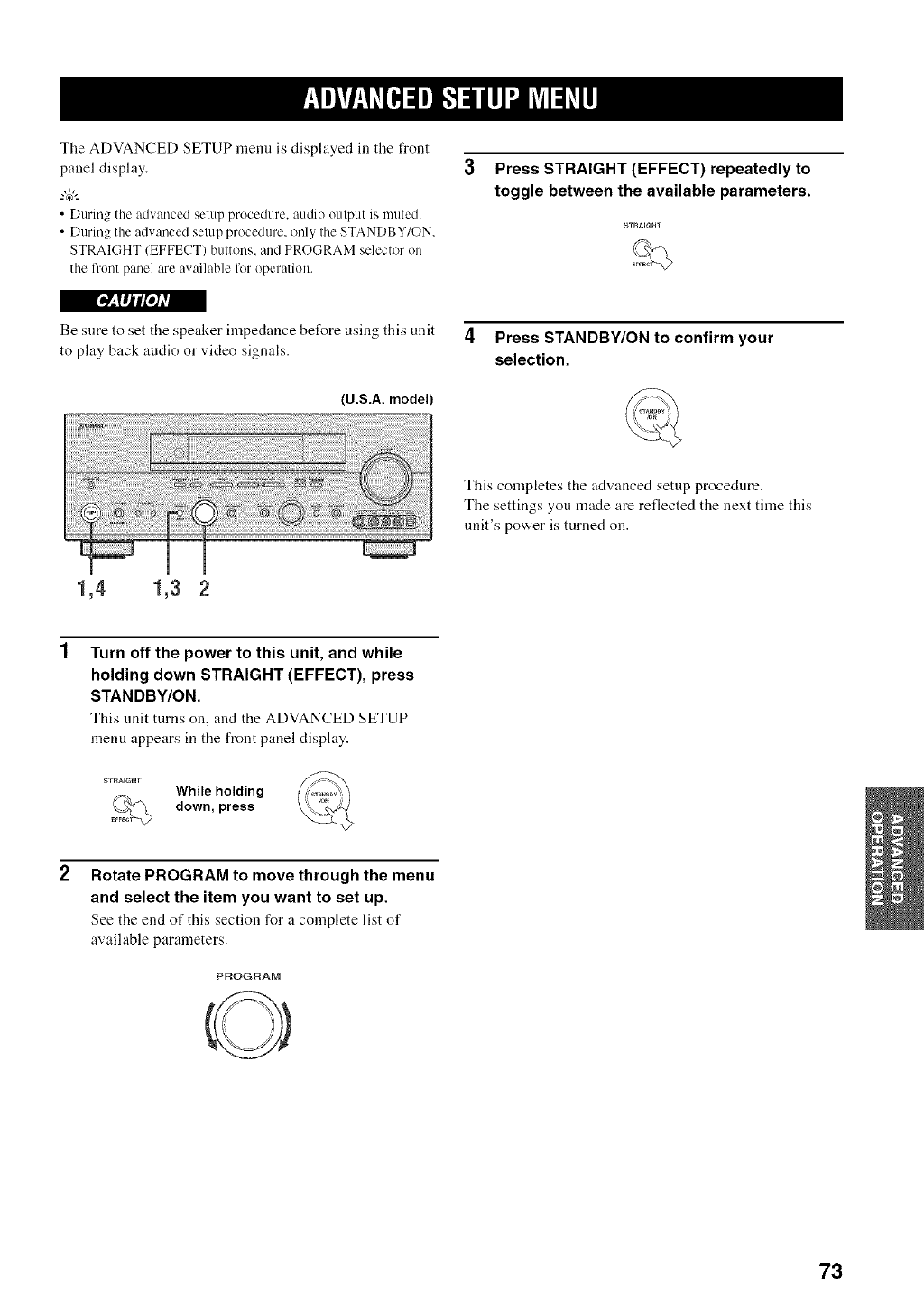
The ADVANCED SETUP menu is displayed in the front
panel display.
--'4_'--
• During the advanced setup procedure, audio output is muted.
• During the advanced setup procedure, only tile STANDBY/ON.
STRAIGHT (EFFECT) buttons, and PROGRAM selector on
tile front panel are available liar operation.
3Press STRAIGHT(EFFECT) repeatedly to
toggle between the available parameters.
['_'a!Ii'l[oJAVl
Be sure to set the speaker impedance before using this unit 4Press STANDBY/ON to confirm your
to play back audio or video signals, selection.
(U.S.A. model)
This completes the advanced setup procedure.
The settings you made are reflected the next time this
unit's power is turned on.
1,4 1,3 2
Turn off the power to this unit, and while
holding down STRAIGHT (EFFECT), press
STANDBY/ON.
This unit turns on, and the ADVANCED SETUP
menu appears in the front panel display.
STRAIGHT While holding
down, press
Rotate PROGRAM to move through the menu
and select the item you want to set up.
See the end of this section for a complete list of
available parameters.
PROGRAD1
73
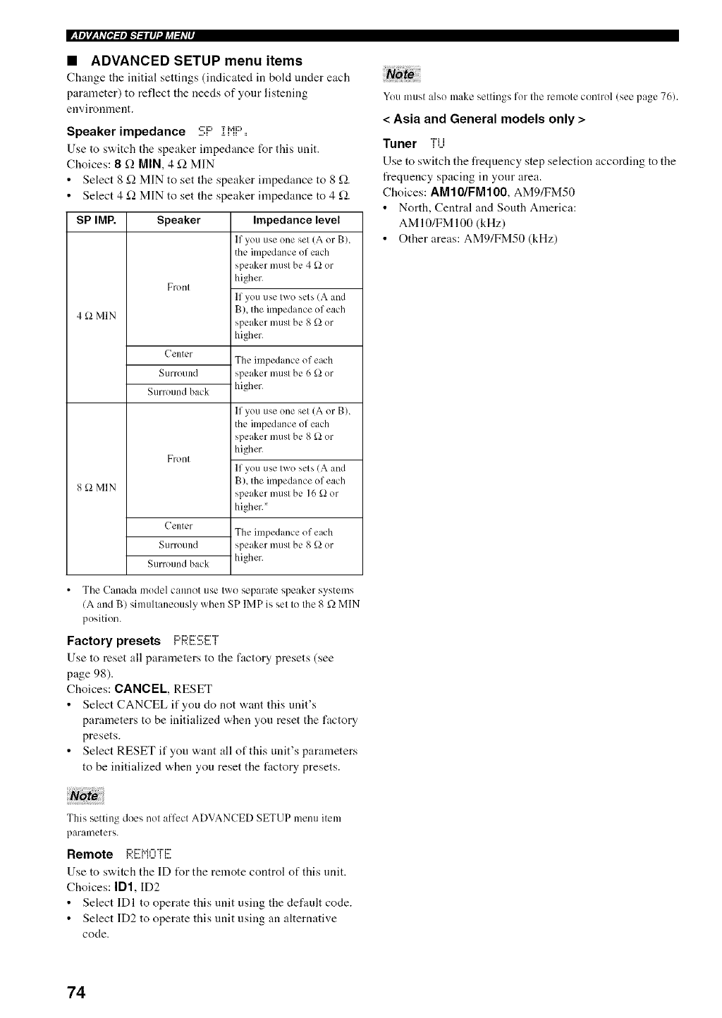
•ADVANCED SETUP menu items
Change the initial settings (indicated in hold under each
parameter) to reflect the needs of your listening
environment.
Speaker impedance ,::=::,.rJ.,_:::,
Use to switch the speaker impedance for this unit.
Choices: 8 £-2MIN, 4 (2 MIN
• Select 8 _22MIN to set the speaker impedance to 8 (2.
• Select 4 (2 MIN to set the speaker impedance to 4 £-2.
SP IMP. Speaker
4 _2MlN
8 _ MIN
Fronl
Center
Stlrroulld
Surround back
Fronl
Center
Stlrrotlnd
Surround back
Impedance level
If you use one set (A or BL
the impedance of each
speaker must be 4 _.) or
higher.
If you use two sets (A and
B)_ the impedance of each
speaker mtlst be 8 _.) or
higher.
The impedance of each
speaker musl be 6 £.)or
higher.
If you use one set (A or B),
the impedance of each
speaker most be 8 _.) or
higher.
If you use two sets (A and
B), the impedance of each
speaker must be 16 _.)or
higher.
The impedance of each
speaker musl be 8 _.)or
higher.
• The Canada modelcannot use two separate speaker systems
(A and B) simultaneously when SP IMP is set to the 8 f_ MIN
position.
Factory presets I:::'F;;:i!!E:!!!:i!!7i=
Use to reset all parameters to the f:tctory presets (see
page 98).
Choices: CANCEL, RESET
• Select CANCEL if you do not want this unit's
parameters to he initialized when you reset the factory
presets.
• Select RESET if you want all of this unit's parameters
to be initialized when you reset the factory presets.
Note
You must also make settings for the remote control (see page 76).
< Asia and General models only >
Tuner ri...i
Use to switch the frequency step selection according to the
frequency spacing in your area.
Choices: AM10/FM100, AM9/FM50
• North, Central and South America:
AM 10/FM 100 (kHz)
• Other areas: AM9/FM50 (kHz)
This setting does not affect ADVANCED SETUP menu item
parameters.
Remote I:;I:EM0iE
Use to switch the ID tUr the remote control of this unit.
Choices: ID1, ID2
• Select IDl to operate this unit using the default code.
• Select ID2 to operate this unit using an alternative
code.
74
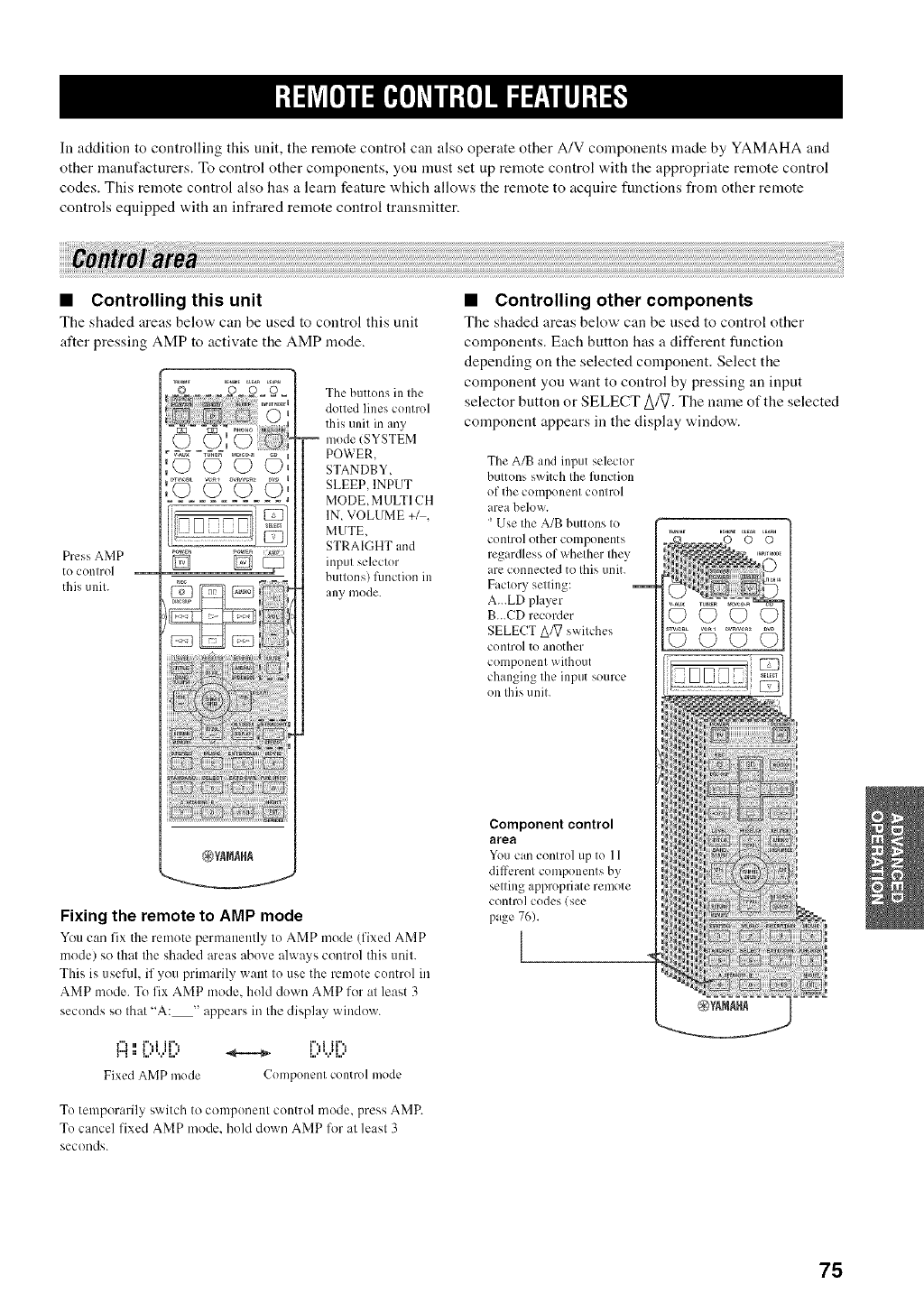
In addition to controlling this unit, the remote control can also operate other A/V components made by YAMAHA and
other mamtfacturers. To control other components, you must set up remote control with the appropriate remote control
codes. This remote control also has a learn feature which allows the remote to acquire functions from other remote
controls equipped with an infrared remote control transmitter.
•Controlling this unit
The shaded areas below can be used to control this unit
after pressing AMP to activate the AMP mode.
Press AMP
{O control
fills unil.
O©
D D_
The buttons in the
dotted lines control
this unit in any
mode (SYSTEM
POWER,
STANDBY,
SLEEP, INPUT
MODE, MULTI CH
IN, VOLUME +_,
MUTE,
STRAIGHT and
input selector
buttons) function ill
{lily mode.
Fixing the remote to AMP mode
You can fix the remote pernl:mently to AMP mode (fixed AMP
model so that the shaded areas above always control this unit.
This is useful, if you primarily want to use the remote control in
AMP mode. To fix AMP mode. hold down AMP for at least 3
seconds so that "A: " appears in the display window.
¢"_, i"..t it".. i"..i it"..
h,a. tH H t tit H i
Fixed AMP mode Componenl control mode
To temporarily switch to component control mode, press AMP.
To cancel fixed A]VIP mode, hokl down AMP for at least 3
seconds.
•Controlling other components
The shaded areas below can he used to control other
components. Each button has a different function
depending on the selected component. Select the
component you want to control by pressing an input
selector button or SELECT Aft7. The name of the selected
component appears in the display window.
The A/B and input selector
buttons switch the function
of the component control
area below.
' Use the A/B buttons to
control other components
regardless of whether they
are connected to this unit.
Factory setting:
A...LD player
B...CD recorder
SELECT AA] switches
control to another
component without
changing the input source
on this unit.
Component control
area
Youcan control up to l 1
different components by
setting appropriate remote
control codes (see
page 76).
l
75
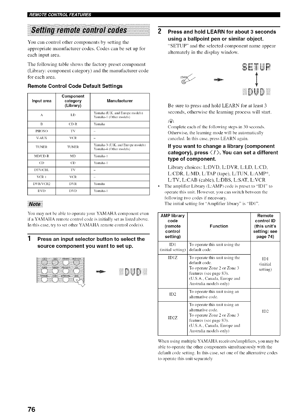
You can control other components by setting the
appropriate manufacturer codes. Codes can be set up for
each input area.
The following table shows the factory preset component
(Library: component category) and the manufacturer code
for each area.
Remote Control Code Default Settings
Component
Input area category Manufacturer
(Library)
AI,I) Yamaha (UK and Imope mo&qs)
Yamaha I tother models)
I3 CI) R Yamaha
PHONO TV
VAUX VCR
TUNIR TUNLR Yamaha 3 (UK and Europe models)
Yamaha 4 tother modelsi
MI)/CI) R MI) Yam d_a I
CI) CI) Yamaha I
I)TV/CBI, "I'V
VCR I VCR
DVRfVCR2 DVR Yamaha
I)VI) I)VI) Yamaha I
N:ato
You may nut be able tu operate your YAMAHA component e,,en
if a YAMAHA remute control code is inilially set as listed abo,, e.
In this case. try to set olher YAMAHA remute cunlrul cude(s).
1 Press an input selector button to select the
source component you want to set up.
Press and hold LEARN for about 3 seconds
using a ballpoint pen or similar object.
"SETUP" and the selected component name appear
alternately in the display ,a,indo,a,.
Be sure to press and hold LEARN %r at least 3
seconds, otherwise the learning process will start.
-#-
Completeeach of the following steps in 30 secunds.
Otherwise. the learning mode will be autumatically
canceled. In this case, press LEARN again.
If you want to change a library (component
category), press < /). You can set a different
type of component.
Library choices: L:DVD, L:DVR, L:LD, L:CD,
L:CDR, L:MD, L:TAP (tape), L:TUN, L:AMP*,
L:TV, L:CAB (cable), L:DBS, L:SAT, L:VCR
The amplifier Library/L:AMP) code is preset to "IDI" to
uperate this unit. However. you can switch between the
following two cudes if necessary.
The initial setting for "Amplifier library" is "IDI".
AMP library Remote
code control ID
(remote Function (this unit's
control setting: see
setting) page 74)
ID 1 To operate this unit using the
(initial setting) default code.
IDIZ To operate this unit using the IDI
default code. (initial
To operate Zone 2 or Zone 3 setting)
features (see page 83).
(U.S.A., Canada, Europe and
Australia models only)
ID2 To operate this unit using an
alternative code.
To operate this unit using an
alternative code. ID2
ID2Z To operate Zone 2 or Zone 3
features (see page 83).
(U.S.A., Canada, Europe and
Australia models only)
When using multiple YAMAHA receivers/amplifiers, you may be
able to operate the other cumpouents simultaneously with the
default code setting. In this case. set one uf the alternative cudes
to uperate this unit separately
76
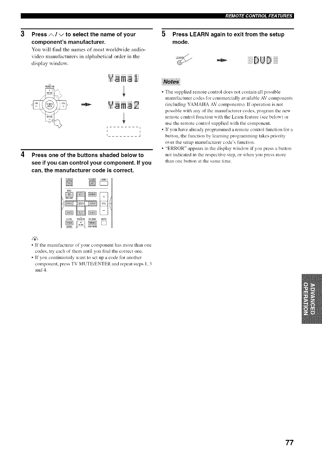
./:Ij_[O]I:IgO]_TII:{O]II::Y_,|II]:_.-'_. ""
Press A/vto select the name of your
component's manufacturer.
You v,,ill find the munes of most worldv,,ide audio-
video manufacturers in alphabetical order in the
display window.
A
PaE_Er,_
dill N
kI
I I
Ij
Press one of the buttons shaded below to
see if you can control your component. If you
can, the manufacturer code is correct.
_WER POWER _W :
LEWL Pa£_ _ a_ MUTE
•If the mailtlfacturer of yotlr component has more than ()lie
codes, try each of them until you find the correct one.
•If you continuously want to set up a code k>r another
component, press TV MUTE/ENTER and repeat steps 1.3
and 4.
Press LEARN again to exit from the setup
mode.
•The supplied remote control does not contain all possible
manufacturer codes for commercially available AV components
/including YAMAHA AV components). If operation is not
possible with any of the manufacturer codes, program the new
remote control function with the Learn feature (see below) or
use the remote control supplied with the component.
• If you have already programmed a remote control fimction %r a
button, the function by learning programming takes priority
over the setup manufacturer code's flmction.
• "ERROR" appears in the display window if you press a button
not indicated in the respective step, or when you press more
than one button at the same time.
77
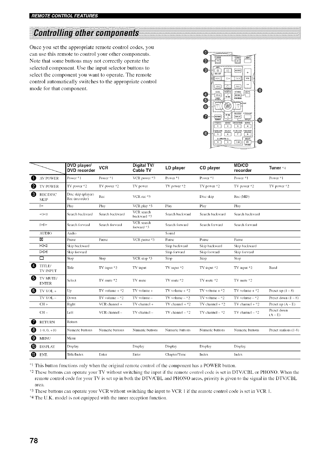
|:/:[j_[O]I_[gO]_TII:{O]I_ff.,__,|II]:/:[_
Once you set the appropriate remote control codes, yon
can use this remote to control your other components.
Note that some buttons may not correctly operate the
selected component. Use the input selector buttons to
select the component you want to operate. The remote
control automatically switches to the appropriate control
mode for that component.
O ....
O ....
O ....
@-
IIZ!B [£EEl_ EE2]i
@
"0
-"-----........... DVD player/ VCR Digital TV/ LD player CD player MD/CD Tuner ,4
DVD recorder Cable TV recorder
POWIR I
TV 2 TV =2 "l'V TV =2 "l'V 2 TV ;2 TV 2PC)WEI_ powel powel power pow_,=
R[ C/DISL" Disc skip
VL'P. se;tr_ h
b t_ kw;lrd =;3
VL'P. se;trch
AUDIO hu_lio S_ul_d
I'i_ Pause P_![Ise VCP. p;tLIse *3 P_tlse P_ltlse P_[Ise
Skip h kward Skip l_a k_lr{l Skip kl_ k_*rd Skip kl_k_xar_l
[] Stop S_op VL'P. slop ;3 Slop Slop S_op
Tilk" TV inptlt :;2 "I'V i_p[ll TV i_l[?tlt ;2 "I'V i_[}[ll 2 TV in[}tlt 2 g_lIld
TV INPUT
S_'l_'c_ TV m_lle _2 "I'V milts" TV mul_" 2 "I'V m[ll_" ;2 TV mille _2
MUTE/
I NTI I;:
TV _olume :;2 "l'V _oIume "l'V _oIume *2 TV _ol[Ime _2 TV _oItlme *2 l)_e_etV()I, LIp+ + + + + + tip (I 8)
TV V()I, Ii){_w_] TV _{}lum_" 2 TV _oiume TV _oitlm_" ;2 TV _{_[um_" :;2 TV _{_[tlm_" 2 I_es&'l{io_n (1 8)
CH + Righl V(iR ch Im]_'l + "l'V ch mn_'l + TV ch_mn{I + ::2 TV on,impel + ;2 TV ch tm]_'l + _2 Pr_'s_'l tip (A I}
])leS_,t (I{_\ i1
CH I.elt VCP. c h tm]_'l TV ch tm]_'l TV c h_lm]_'l 2 TV on,Impel ;2 TV ch mn_'l 2 ( A I)
I).I TURN Re'turn
OI 9.0. +10 Ntlmeric b[l[Iolls Ntlmelic b[ll{(}lls Ntlmelic btlll{)lls Ntll]lelic b[lllolls Ntlmelic btlll{)lls Ntllnelic 13[llk}lls Pleset s[ iIi{}lls (] 8)
MINU Mellu
I[_ HSPI,AY DispI;t) Displal) DispI I_ DispI;I) Displal)
Tille/In/lex Inle] Enle_ hldex hl/lexINT (2 h;ll?lel fI'ime
'l This button functions only when the original remote control of the component has a POWER button.
2 These buttons can operate your TV without switching the input if the remote control code is set in DTV/CBL or PHONO. When the
remote control code for your TV is set up in both the DTV/CBL and PHONO areas, priority is given to the signal in the DTV/CBL
area.
_3These buttons can operate your VCR without switching the input to VCR I if the remote control code is set in VCR I.
'4 The U.K. model is not equipped with the tuner reception function.
78
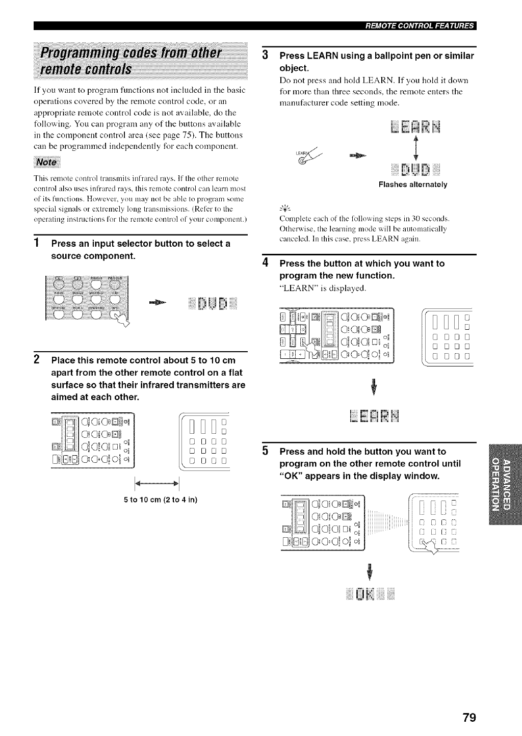
.l:h_[o]l:lgo]dll:{o]ll::Y__|ll]l_.-'_. ""
If you want to program functions not included in the basic
operations covered by the remote control code, or an
appropriate remote control code is not available, do the
following. You can program any of the buttons available
in the component control area (see page 75). The buttons
can be programmed independently for each component.
This remote control transmits infrared rays. If the other remote
control also uses infrared rays, this remote control can learn most
of its functions. However, you may not be able to program some
special signals or extremely long transmissions. (Refer to the
operating instructions for the remote control of your component.)
1 Press an input selector button to select a
source component.
Place this remote control about 5 to 10 cm
apart from the other remote control on a flat
surface so that their infrared transmitters are
aimed at each other.
DDD°
o
° °oo
BE}BO
0 000
5 to 10 cm (2 to 4in)
Press LEARN using a ballpoint pen or similar
object.
Do not press and hold LEARN. If you hold it down
for more than three seconds, the remote enters the
manufacturer code setting mode.
I : I;I I ,= _,;I
I_aL; FI IN
- !
Flashes alternately
Complete e:_ch of the following steps in 30 seconds.
Otherwise. the learning mode will be automatically
canceled. In this case. press LEARN again.
Press the button at which you want to
program the new function.
"LEARN" is displayed.
O!OlOs@!oi
00°0! ol o_ I °
[J[JI °
0 000
0 00°
@ @80
i=: ii; M J:=_ii_i
Press and hold the button you want to
program on the other remote control until
"OK" appears in the display window.
Ja- HO O O=B Bill, =
@ I-IIo=o;o, Di01Iiii =......N _i _1_ i
D is]o-o0oiq41
i!i!iiiiii!!iU!_lii!i!iiiiii!i!i[!iiiii!!i,i!!
79
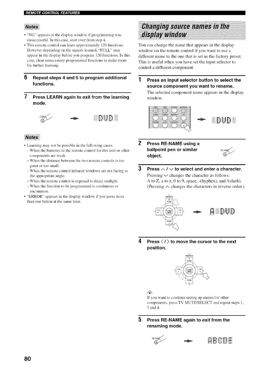
•"NG" appears in tile display window if programming was
unsuccessful. In this case. start over from step 4.
• This remote control can learn approximately 120 functions.
However depending on the signals learned. "FULL" may
appear in the display before you program 120 functions. In this
case. clear unnecessary programmed fllnctiollS to make room
for further learning.
6Repeat steps 4 and 5 to program additional
functions.
7Press LEARN again to exit from the learning
mode.
Yon can change the name that appears in the display
window on the remote control if yon want to use a
different name to the one that is set as the factory preset.
This is nsefld when you have set the input selector to
control a different component.
Press an input selector button to select the
source component you want to rename.
The selected component name appears in the display
window.
iiiiiiiiiiiii!!!!>UBiiiiiiiii!i
•Learning may not be possible in the following cases:
When the batteries in the remote control for this unit or other
components are weak.
When the distance between the two remote controls is too
great or too small.
When the remote control infrared windows are not facing at
the appropriate angle.
When the remote control is exposed to direct sunlight.
When the function to be programmed is continuous or
/lncoinnlon.
• "ERROR" appears in the display window if you press more
than one button at the same time.
Press RE-NAME using a
ballpoint pen or similar
object.
Press A/",/to select and enter a character.
Pressing ",/changes the character as follows:
A to Z, a to z, 0 to 9, space, -(hyphen), and/(slash).
(Pressing/x changes the characters in reverse order.)
A
4Press </>to move the cursor to the next
position.
If you want to continue setting up names for other
components, press TV MUTE/SELECT and repeat steps I.
3 and 4.
Press RE-NAME again to exit from the
renaming mode.
i;iE!{;DE;
80
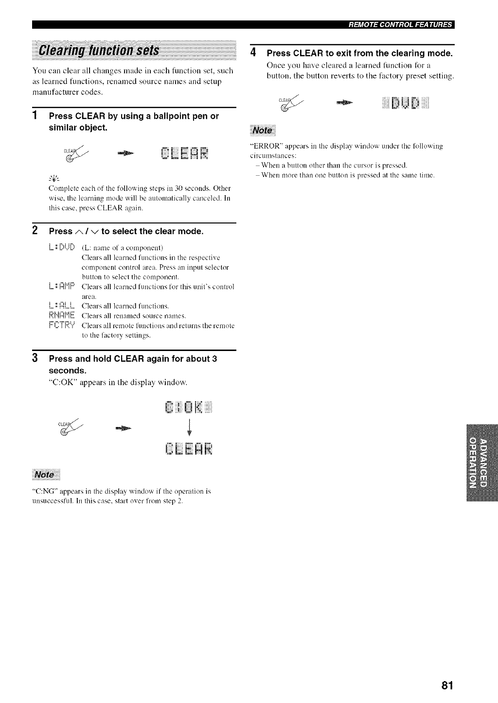
.]:/j_[o]l:lgo]_rll:{o]ll::V__|ll]l_.-'_. ""
You can clear all changes made ill each function set, such
as learned functions, renamed source names and setup
mannfacturer codes.
Press CLEAR by using a ballpoint pen or
similar object.
F3LI::E
Complete each of the following steps ill 30 seconds. Other
wise. the learning mode will be automatically canceled. In
this case, press (!LEAR again.
Press/,, /vto select the clear mode.
i . i'*'*iiF",
i . i"lj.¢_::,
i . rli i
/L: name of a component)
Clears all learned functions in the respective
componeut control area. Press all input selector
button to select tile component.
Clears all learned functions for this unit's control
area.
Clears all learned functions.
Clears all renamed source names.
Clears all remote flmctions and returns the remote
to the factory settings.
3 Press and hold CLEAR again for about 3
seconds.
"(.':OK" appears in the display window.
Press CLEAR to exit from the clearing mode.
Once you have cleared a learned function for a
button, the button reverts to the factory preset setting.
"ERROR" appears ill tile display window under tile fffllowiug
circun/stances:
When a button other than the cursor is pressed.
When more than one button is pressed at the same time.
"C:NG" appears in tile display wiudow if the operation is
unsuccessfuh In this case. start oxer from step 2.
81
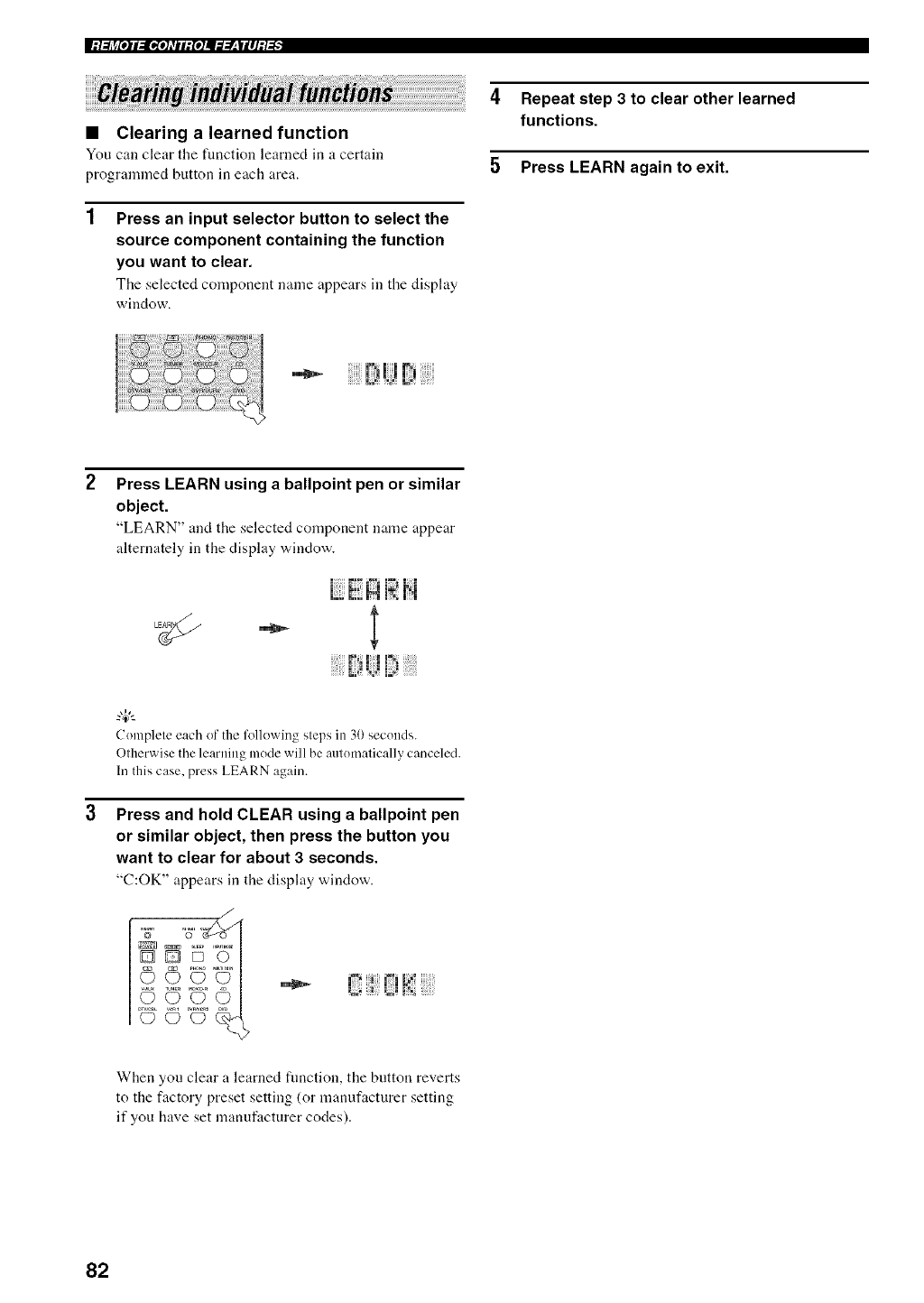
•Clearing a learned function
You can clear the fuuction learned in a certain
programmed button in each area.
Press an input selector button to select the
source component containing the function
you want to clear.
Tile selected compouent name appears in the display
window.
4Repeat step 3 to clear other learned
functions.
5 Press LEARN again to exit.
Press LEARN using a ballpoint pen or similar
object.
"LEARN" and the selected component name appear
alternately in the display window.
LiiN N N
::22:!_2_ :::::
Complete each of the following steps in 30seconds.
Otherwisethe learning mode will be automatically canceled.
In this case, press LEARN again.
Press and hold CLEAR using a ballpoint pen
or similar object, then press the button you
want to clear for about 3 seconds.
"(.':OK" appears in the display window.
J
/
When you clear a learned function, the button reverts
to the factory preset setting (or manufacturer setting
if you have set manufacturer codes).
82
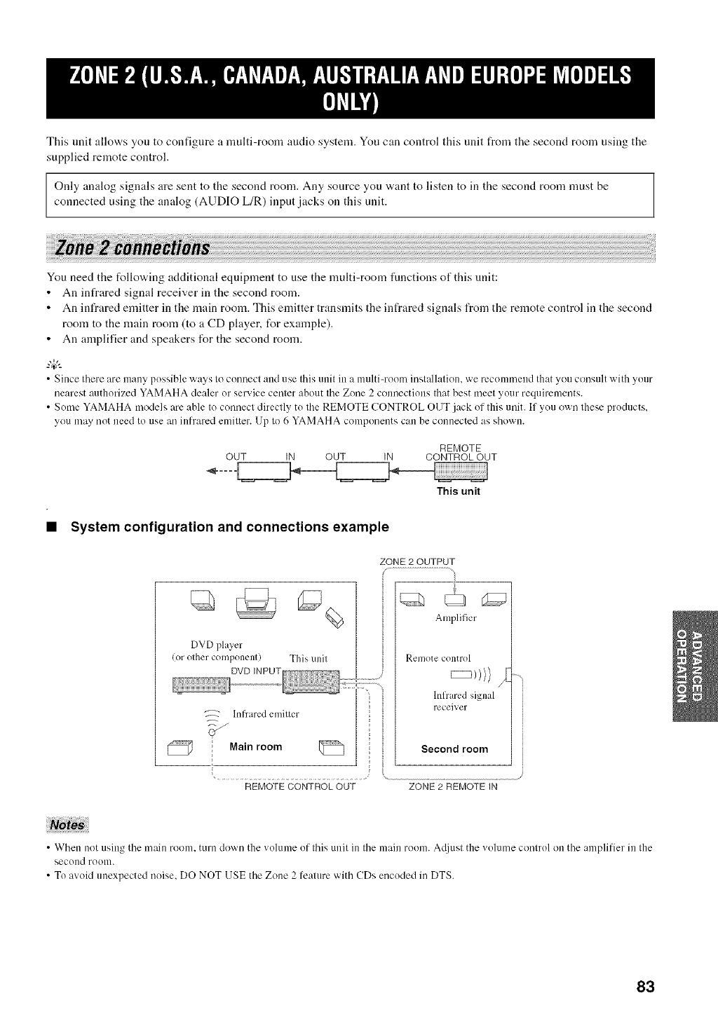
This unit allows you to configure a multi-room audio system. You can control this unit from the second room using the
supplied remote control.
Only analog signals are sent to the second room. Any source you want to listen to in the second room must be
connected using the analog (AUDIO L/R) input jacks on this unit.
You need the following additional equipment to use the multi-room fimctions of this unit:
• An infrared signal receiver in the second room.
• An infrared emitter in the main room. This emitter transmits the infrared signals from the remote control in the second
room to the main room (to a CD player, for example).
• An amplifier and speakers for the second room.
• Since there are many possibleways to connect and use this unit in a multi-room installation, we recommend thatyou consult with your
nearest authorized YAMAHAdealer or service center about the Zone 2 connections thatbest meet your requirements.
• Some YAMAHA models are able to connect directly to the REMOTE CONTROL OUT .jackof this unit. If you own these products,
you may not need to use an infrared emitter. Up to 6 YAMAHAcomponents can be connected as shown.
REMOTE
OUT IN OUT IN CONTROLOUT
This unit
•System configuration and connections example
DVD player
(or olher componenl) This unil
Infrared emiller
Mainroom
ZONE 2 OUTPUT
Amplifier
Remote connol
hffrared signal
receiver
Second room
REMOTE CONTROL OUT ZONE 2 REMOTE iN
• Wl'len not using the main room, turn down the ,.olume of this unit in the main room. Ac[jusl the ,.olume control on the amplifier in the
second room.
• To avoid unexpected noise, DO NOT USE the Zone 2 fealure with CDs encoded in DTS.
83
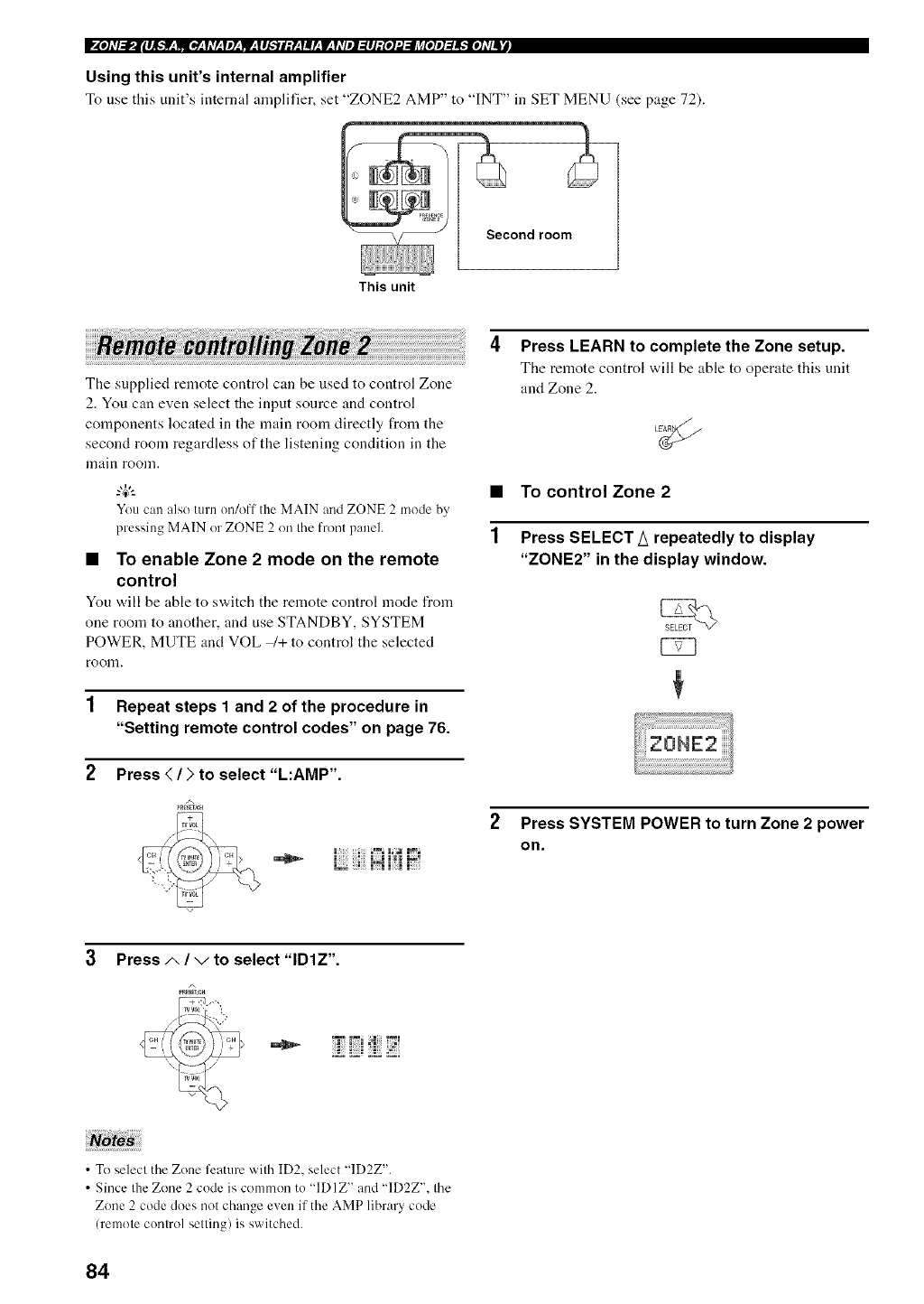
Using this unit's internal amplifier
To use this unit's internal amplifier, set "ZONE2 AMP" to "INT" in SET MENU (see page 72).
1
This unit
The supplied remote control can be used to control Zone
2. You can even select the input source and control
components located in the main room directly from the
second room regardless of the listening condition in the
lnaii_l rooln.
You can also turn on/off the MAIN and ZONE 2 mode by,
pressing MAIN orZONE 2 on the front panel.
• To enable Zone 2 mode on the remote
control
You v,,ill be able to switch the remote control mode from
one room to another, and use STANDBY, SYSTEM
POWER, MUTE and VOL _+ to control the selected
room.
1 Repeat steps 1 and 2 of the procedure in
"Setting remote control codes" on page 76.
2Press </) to select "L:AMP".
A
4
1
Press LEARN to complete the Zone setup.
The remote control will be able to operate this unit
and Zone 2.
To control Zone 2
Press SELECT/_ repeatedly to display
"ZONE2" in the display window.
Press SYSTEM POWER to turn Zone 2 power
on.
3Press .t', /",/to select "IDIZ".
/\
•To select the Zone feature with ID2, select "]D2Z".
• Since the Zone 2 code is common to "IDIZ" and "]D2Z", the
Zone 2 code does not change even if the AMP library code
(remote control setting) is switched.
84
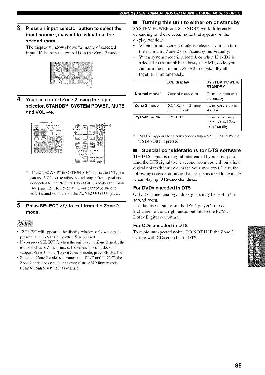
Press an input selector button to select the
input source you want to listen to in the
second room.
Tile display windo'a, shows "2: name of selected
input" if the remote control is in the Zone 2 mode.
4You can control Zone 2 using the input
selector, STANDBY, SYSTEM POWER, MUTE
and VOL -/+.
* If "ZONE2 AMP" in OPTION MENU is set to INT. you
can use VOL _+ to adjust sound output from speakers
connected to the PRESENCE/ZONE 2 speaker terminals
/see page 72). However. VOL q+ cannot be used to
a@lst sound output from the ZONE2 OUTPUT jacks.
Press SELECT/_/V to exit from the Zone 2
mode.
• "ZONE2" will appear in the display window only when A is
pressed, and SYSTM only when V is pressed.
• If you press SELECT A when the unit is set to Zone 2 mode. the
unit switches to Zone 3 mode. However. this unit does not
support Zone 3 mode. To exit Zone 3 mode, press SELECT V.
• Since the Zone 2 code is common to "IDIZ" and "ID2Z". the
Zone 2 code does not change even if the AMP library code
(remote control setting) is switched.
• Turning this unit to either on or standby
SYSTEM POWER and STANDBY work differently
depending on the selected mode that appears on the
display window.
• When normal, Zone 2 mode is selected, you can turn
the main unit, Zone 2 to on/standby individually.
• When system mode is selected, or when IDI/ID2 is
selected as the amplifier library (L:AMP) code, you
can turn the main unit, Zone 2 to on/standby all
together sinmltaneously.
LeD display SYSTEM POWER/
STANDBY
Normal mode Name of component Turns the main unit
on/standby
Zone 2mode "ZONE2" or "2:name Turns Zone 2 to on/
of component" standby
System mode "SYSTM" Turns evm.wthing (the
main unit and Zone
2) on/standby
'"MAIN" appears for a few seconds when SYSTEM POWER
or STANDBY is pressed.
•Special considerations for DTS software
The DTS signal is a digital bitstream. If you attempt to
send the DTS signal to the second room you "a,ill only hear
digital noise (that may damage your speakers). Thus, the
following considerations and adjustments need to be made
when playing DTS-encoded discs.
For DVDs encoded in DTS
Only 2 channel analog audio signals may be sent to the
second rOOlll.
Use the disc menu to set the DVD player's mixed
2-channel left and right audio outputs to the PCM or
Dolby Digital soundtrack.
For CDs encoded in DTS
To avoid unexpected noise, DO NOT USE the Zone 2
feature with CDs encoded in DTS.
85
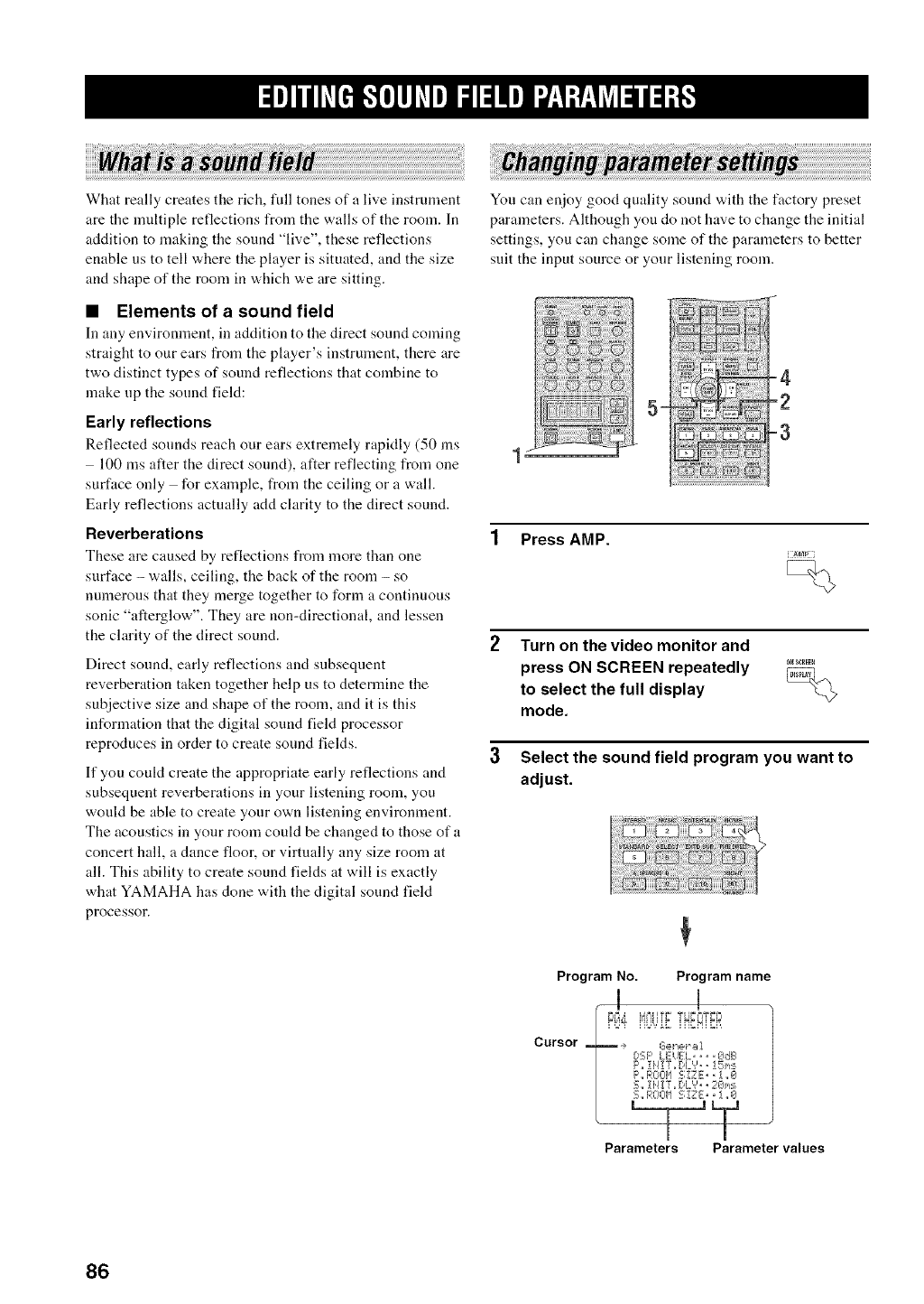
What really creates the rich, full tones of a live instrument
are the multiple reflections from the walls of the room. In
addition to making the sound "live", these reflections
enable us to tell where the player is situated, and the size
and shape of the room in which we are sitting.
You can enjoy good quality sound with the factory preset
parameters. Although you do not have to change the initial
settings, you can change some of the parameters to better
suit the input source or your listening room.
•Elements of a sound field
In any environnlent, ill addition to the direct sound comiug
straight to our ears from the player's instrument, there are
two distinct types of sound reflections that combine to
make up the sound field:
Early reflections
Reflected sounds reach our ears extremely rapidly (50 ms
100 ms after the direct sound), after reflecting from one 1
surface only for example, from the ceiling or a wall.
Early reflections actually add clarity to the direct sound.
Reverberations
These are caused by reflections from more than one
surface - walls, ceiling, the back of the room - so
numerous that they merge together to form a continuous
sonic "afterglow". They are non-directional, and lessen
the clarity of the direct sound. 2
Direct sound, early reflections and subsequent
reverberation taken together help us to determine the
subjective size and shape of the room, and it is this
information that the digital sound field processor
reproduces in order to create sound fields. a
If you coukt create the appropriate early reflections and
subsequent reverberations in your listening room, you
would be able to create your own listening environment.
The acoustics in your room could be changed to those of a
concert hall, a dance floor, or virtually any size room at
all. This ability to create sound fields at will is exactly
what YAMAHA has done with the digital sound field
processor.
=
1 Press AMP.
[t_M_3
Turn on the video monitor and
press ON SCREEN repeatedly ........
to select the full display _
mode.
Select the sound field program you want to
adjust.
Program No. Program name
-1 I
Cursor _ .+ L?elt,_,__A
ESF' 1Ei,JE'L, ,, _Jd_l
P., R01._I['I '-_ !7E" • 1 ,, 1.7._
5..!H!r_ r.,L','.,2C>c_
S., ROL-II'I S _;_" " _ _,I;£1
Parameters Parameter values
86
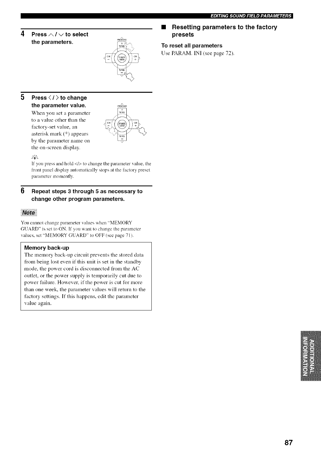
Press A/vto select
the parameters.
_m]ill_T[ej_o]lj_Tlel_l_llei.j:1;y:li_l:ll3:;- -
•Resetting parameters to the factory
presets
To reset all parameters
Use PARAM. IN] (see page 72).
Press (/)to change
the parameter value. _,,_.,..
When you set a parameter
to a value other than the
factory-set value, an
asterisk mark (*) appears
by the parameter name on
the on-screen display.
If you press and hold </> to change the parameter value, the
front panel displW automatically stops at the factory preset
parameter monlently.
Repeat steps 3 through 5 as necessary to
change other program parameters.
You cannot change parameter values when "MEMORY
GUARD" is set to ON. If you want to change the parameter
wdues, set "MEMORY GUARD" to OFF (see page 71).
Memory back-up
The memory back-up circuit prevents the stored data
from being lost even if this unit is set in the standby
mode, the power cord is disconnected from the AC
outlet, or the power supply is temporarily cut due to
power failure. However, if the power is cut for more
than one week, the parameter values will return to the
factory settings. If this happens, edit the parameter
value again.
87
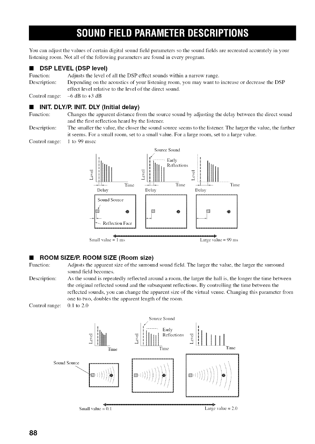
You call adjust the values of certain digital sound field parameters so the sound fields are recreated accurately in your
listening room. Not all of the following parameters are found in every program.
• DSP LEVEL (DSP level)
Fuuction: Adjusts the level of all the DSP effect sounds within a narrow range.
Description: Depending on the acoustics of your listening room, you may want to increase or decrease the DSP
effect level relative to the level of the direct sound.
Control range: -6 dB to +3 dB
•INIT. DLY/P. INIT. DLY (Initial delay)
Function: Changes the apparent distance from the source sound by adjusting the delay between the direct sound
and the first reflection heard by the listener.
Description: The smaller the value, the closer the sound source seems to the listener. The larger the value, the farther
it seems. For a small room, set to a small value. For a large room, set to a large value.
Control range: 1 to 99 msec
Source Sound
u¢/ Early
II Refleclions
_-_1_ Time __L._ Time k_ Time
Delay Delay Delay
I_ Refleclion Face
Small value = 1 ms Large value = 99 ms
•ROOM SIZE/P. ROOM SIZE (Room size)
Function: Adjusts tire apparent size of the surround sound field. The larger the value, the larger the surround
sound field becomes.
Description: As the sound is repeatedly reflected around a room, the larger the hall is, the longer the time between
the original reflected sound and the subsequent reflections. By controlling the time between the
reflected sounds, you can change the apparent size of the virtual venue. Changing this parameter from
one to two, doubles the apparent length of the room.
Control range: 0.1 to 2.0
Sound Source
I
.2
Tilne
Source Sound
_ _Reflections _
Time Tilne
<
Small value = 0. I Large value = 2.0
88
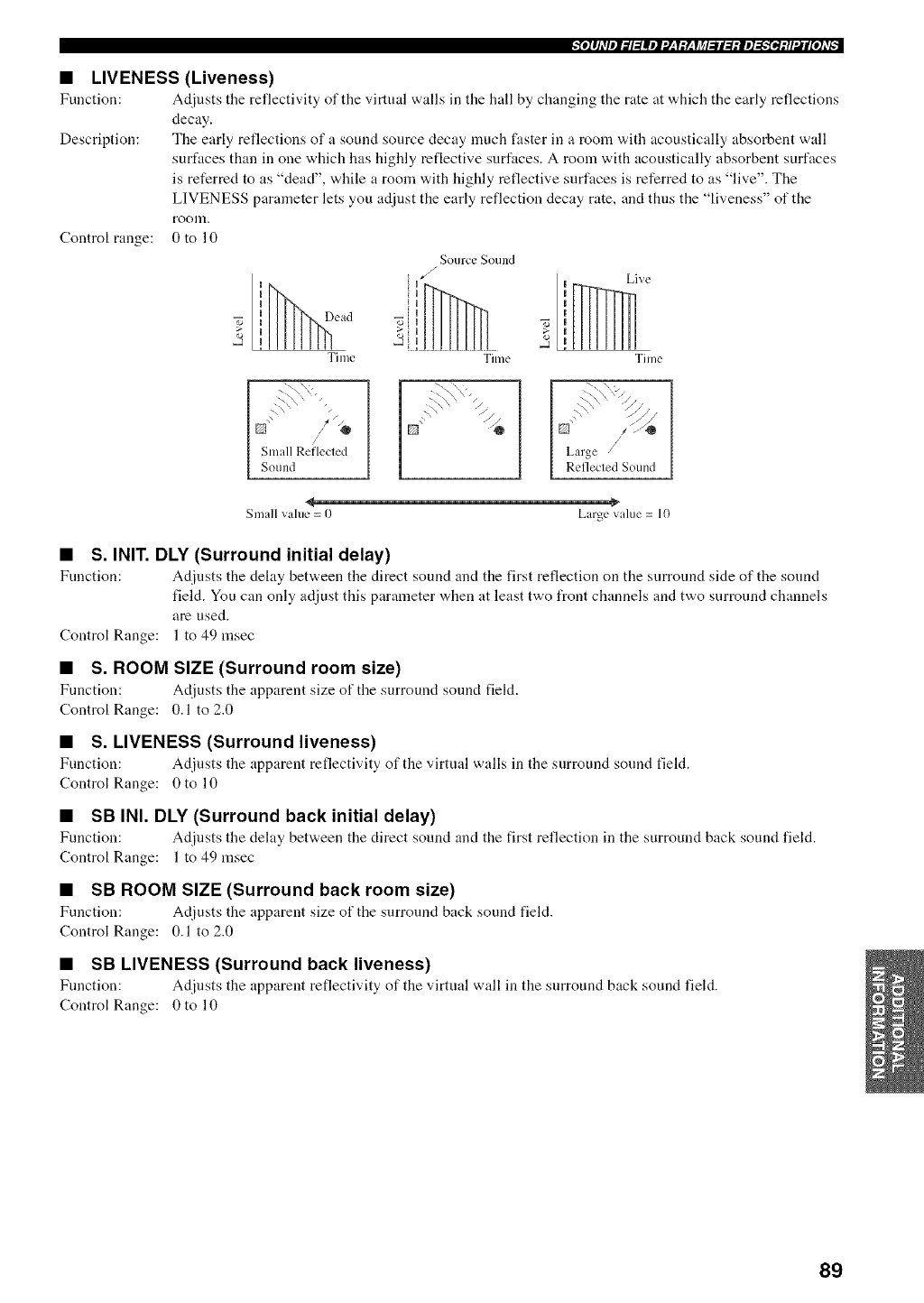
"_o]lhqel_l:lllel'.]:Y:Y:YJ_l:ll:l:|e]_e_:H'.il[o]LT_" 1
• LIVENESS (Liveness)
Function: Adjusts tile reflectivity of the virtual walls ill tile hall by changing tile rate at xa,hich tile early reflections
decay.
Description: The early reflections of a sound source decay nmch faster in a room with acoustically absorbent wall
surfaces than in one which has highly reflective surfaces. A room with acoustically absorbent surfaces
is referred to as "dead", while a room with highly reflective surfaces is referred to as "live". The
LIVENESS parameter lets you adjust the early reflection decay rate, and thus the "liveness" of the
roonl.
Control range: 0 to 10
II ead
7',
2Time
Source Sound
Live
Time Time
N" "" /@
Small Rei'lecled
[ Sotlnd
E] _" /._
Small vahle = 0 Large value = 10
• S. INIT. DLY (Surround initial delay)
Function: Adjusts the dehty bet'a, een tile direct sound and tile first reflection on the surround side of the sound
field. You can only adjust this parameter when at least two front channels and two surround channels
are used.
Control Range: 1 to 49 msec
•S. ROOM SIZE (Surround room size)
Function: Adjusts tile apparent size of the surround sound fiekt.
Control Range: 0.1 to 2.0
•S. LIVENESS (Surround liveness)
Function: Adjusts the apparent reflectivity of the virtual walls in tile surround sound field.
Control Range: 0 to 10
•SB INI. DLY (Surround back initial delay)
Function: Adjusts the delay between the direct sound and the first reflection in tile surround back sound field.
Control Range: 1 to 49 msec
•SB ROOM SIZE (Surround back room size)
Function: Adjusts the apparent size of tile surround back sound field.
Control Range: 0.1 to 2.0
•SB LIVENESS (Surround back liveness)
Function: Adjusts the apparent reflectivity of the virtual wall in the surround back sound field.
Control Range: 0 to 10
89
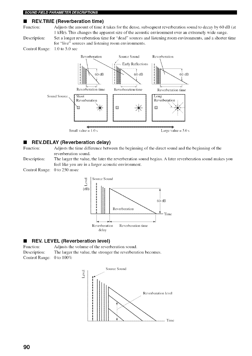
•REV.TIME (Reverberation time)
Function: Adjusts the amount of time it takes for tile dense, subsequent reverberation sound to decay by (,0 dB (at
1 kHz). This changes the apparent size of the acoustic environment over an extremely wide range.
Description: Set a longer reverberation time for "dead" sources and listening room environments, and a shorter time
for "live" sources and listening room environments.
Control Range: 1.0 to 5.0 sec
Reverberalion Source Sound
/
_ U-- Early Reflccti( ns
" 60 dB ii', 60 dB
Reverberation tilne Reverberation time
Sound Source [ Shor/
_Reverberalion ÷
Reverberalion
60 dB
I_ I
Reverberation time
Small vahle = 1.0 s Large vahle = 5.0 s
•REV.DELAY (Reverberation delay)
Function: Adjusts the time difference betv,,een the beginning of the direct sound and the beginning of the
reverberation sound.
Description: The larger the value, the later the reverberation sound begins. A later reverberation sound makes you
feel like you are in a larger acoustic environment.
Control Range: 0 to 250 msec
Source Sound
(dB)
Reverberation
LA.
Reverberation Reverberation tilne
delay
60 dB
Time
•REV. LEVEL (Reverberation level)
Function: Adiusts the volume of the reverberation sound.
Description: The larger the value, the stronger the reverberation becomes.
Control Range: 0 to 100%
Source SOulld
90
@e]lhVel_l:lllel:l-'l:Y-'li_l_ll:l:ie]_e_:tl'_ll[e]LvP I
•DIALG.LIFT (Dialog lift)
Fnnction: Adjusts the height of the front and center channel sounds by assigning some of tile front and center
channel elements to the presence speakers.
Description: The larger the parameter, the higher the position of the front and center channel sound.
Choices: 01112131415,initial setting is 0.
For 2ch Stereo:
•DIRECT (Direct)
Fnnction: Bypasses this unit's decoders and DSP processors for pure high fidelity sound "a,hen playing 2-channel
analog sources.
Choices: AUTO, OFF
•When multi-channel signals/Dolby Digital and DTSI are input, they are downmixed to 2 channels and output from tile front left and
right speakers.
• When "BASS OUT" is set to BOTH. or "FRONT SP" set to SMALL and "BASS OUT" set to SWFR. front left and right speaker low-
frequency signals are redirected to tile subwoofer.
For 7ch Stereo:
Function: These parameters adjust the volume level t_r each channel ill 7-channel stereo mode.
Control Range: 0- 100%
•CT LEVEL (Center level)
•SL LEVEL (Surround left level)
•SR LEVEL (Surround right level)
•SB LEVEL (Surround back level)
•PL LEVEL (Presence left level)
•PR LEVEL (Presence level)
For PRO LOGIC IIx Music and PRO LOGIC II Music:
• PANORAMA (Panorama)
Ftmction: Sends stereo signals to the surround speakers as well as tile front speakers for a wraparound effect.
Choices: OFF, ON
•DIMENSION (Dimension)
Function: Gradually adjusts the sound field either tovvards the front or towards the rear.
Control range: -3 (towards the rear) to +3 (towards the front), initial setting is STD (standard).
•CENTER WIDTH (Center width)
Fnnction: Adjusts the center image from all three front speakers to varying degrees. A larger value adjusts the
center inaage towards the front left and right speakers.
Control range: 0 (center channel sound is outpnt only from center speaker) to 7 (center channel sound is outpnt only
from front left and right speakers)
Initial setting: 3
This parameter can be set only when SUR.STANDARD is selected.
91

For DTS Neo:6 Music:
•C. IMAGE (Center image)
Fnnction: Adjusts tile center image from all three front speakers to varying degrees.
Control range: 0 to 1.0
Initial setting: 0.3
This parameter can be set only when SUR.STANDARD is selecled.
92
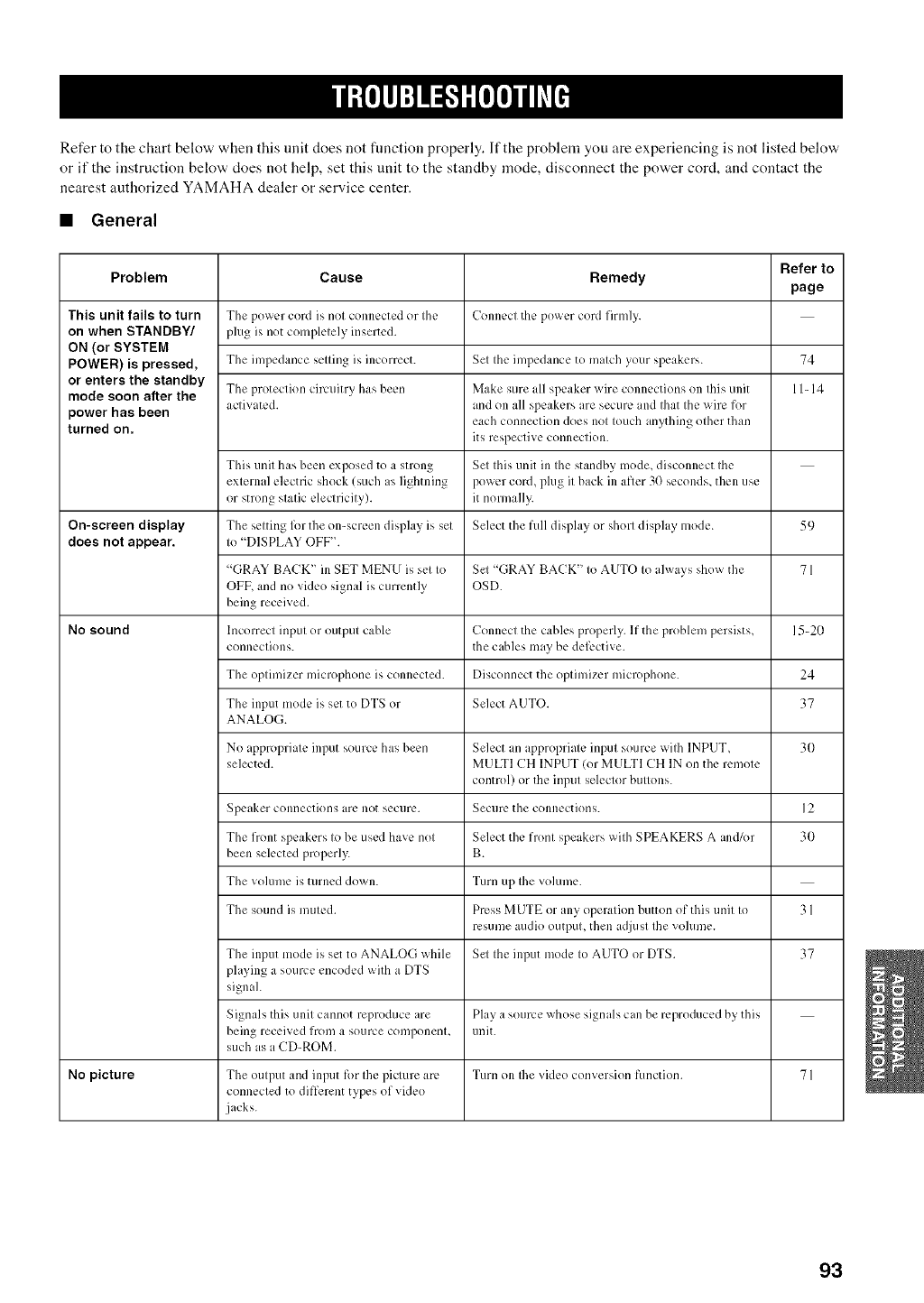
Refer to the chart below when this unit does not fimction properly. If the problem you are experiencing is not listed below,'
or if the instruction below does not help, set this unit to the standby mode, disconnect the power cord, and contact the
nearest authorized YAMAHA dealer or service center.
•General
Refer to
Problem Cause Remedy page
This unit fails to turn The power cord ixnol connected or II1_' Connect tile power cord firmly.
on when STANDBY/ plug is not complelely inserted.
ON (or SYSTEM
POWER) is pressed, The impedance selling ix incorrect. Sel Ihc impedance to malch yo[Ir speakers. 74
or enters the standby
mode soon aRer the The protection circuiny has been Make sure dl speaker wire connections on lifts unit 11-14
power has been aclivated, and on all speakers are secure and Ihat file wire for
each conneclion does nol Iouch anything olher than
turned on, its respective connection.
Tiffs unil has been exposed to a strong Sel Ihisunit in Ihe standby mode, disconnect Ihe
exlernal electric shock (such as lightning power cord, plug il back in afler 30 seconds, then use
or strong slalic elechicily), it normally.
On-screen display The selting 1_)1the on-screen display ix set Select the full display or shorl display lnode. 59
does not appear. Io "DISPLAY OFF".
"(;RAY BACK" in SET MENU is sel Io Sel "GRAYBACK" Io AUTO Io always show the 71
OFF, and no vkleo signal ixcurrently OSD.
being received.
No sound Incorrecl inpul or outpul cable Connecl the cables properly. If the problem persists, 15-20
conneclions, the cables may be dek, ctive.
The oplimizer microphone ix connected. Disconnect the oplimizer microphone. 24
The input mode ix set to DTS or Select AUTO. 37
ANALOG.
No appropriale input source has been Select an appropriale inpul source wilh INPUT, 30
selected. MULTI CH INPUT (or MULTI CH IN on the remole
control) or the inpul seleclor billions.
Speaker connections are not secure. Secure the connections. ] 2
The front speakers Io be used have nol Select the fronl speakers wilh SPEAKERS A and/or 30
been selected properly. B.
The volume is nuned down. Turn up Ihe volume.
The sound is milled. Press MUTE or any operation button of tiffs tlnil Io 31
resume audio outpul, then adjusl Ille vokm/e.
The input mode ix set to ANALOG while Sel Ihe input mode Io AUTO or DTS. 37
playing a source encoded with a DTS
signal.
Signals this unil cannot reproduce are Play a source whose sigmds can be reproduced by,this
being received from a source componenl, unit.
such as a CD-ROM.
No picture The oulput and input Ii)r Ihe piclure are Turn on Ihe video conversion function. 71
connecled to different types of video
jacks.
93
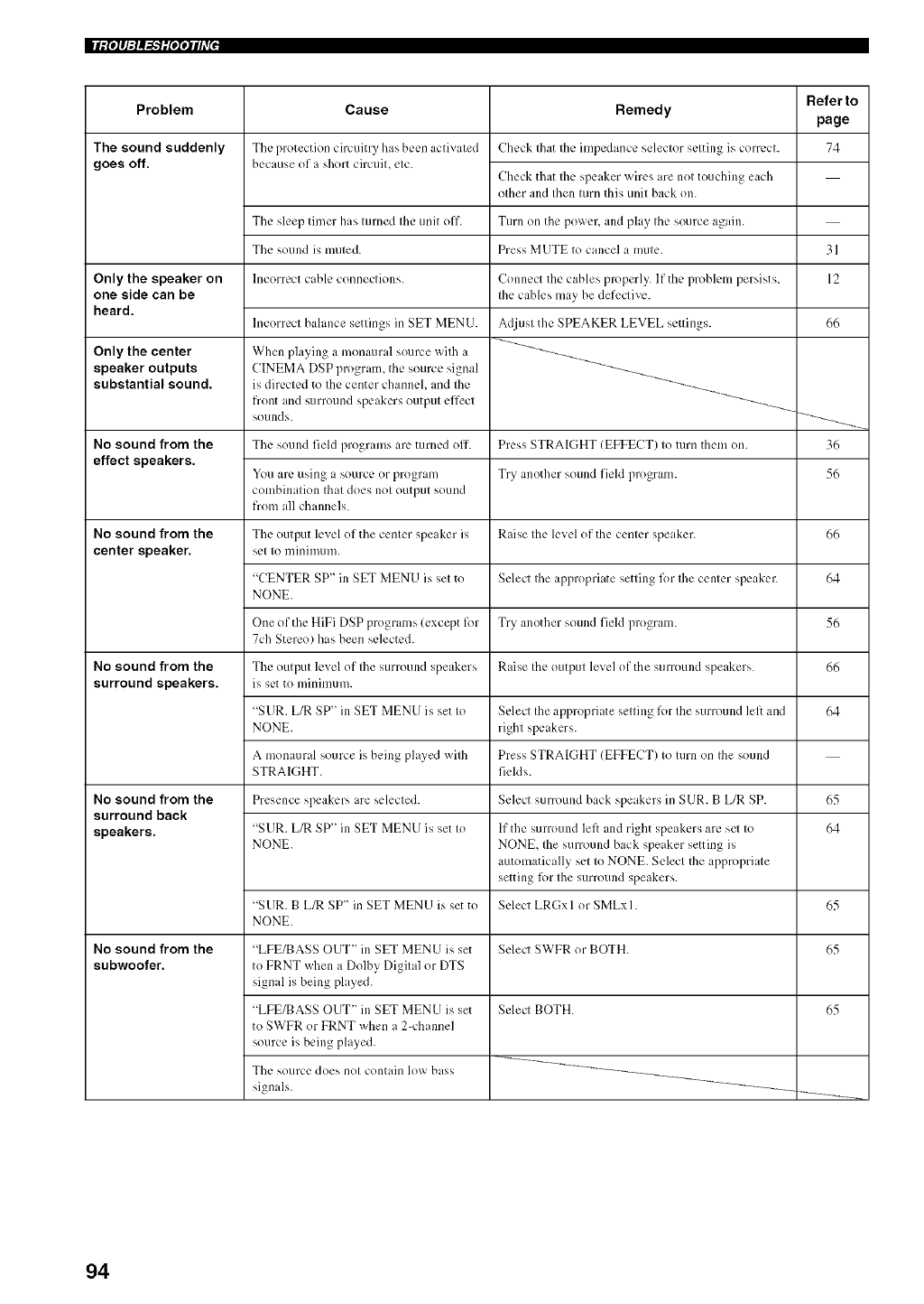
|lill_q:l_"lilqqih7 J
Problem
The sound suddenly
goes off.
Only the speaker on
one side can be
heard.
Only the center
speaker outputs
substantial sound.
No sound from the
effect speakers.
No sound from the
center speaker.
No sound from the
surround speakers.
No sound from the
surround back
speakers.
No sound from the
subwoofer,
Refer to
Cause Remedy page
The protection circuitry has bccn activated Check that the impedance selector setting is correct. 74
because of a short cimuiL etc.
Check that the speaker wires are not touching each
other and then turn this unit back on.
The sleep timer has turned the unit off. Turn on the power, and phly the source again.
The sound is muted. Press MUTE to cancel a mute.
Incorrect cable connections.
Incorrect balance settings in SET MENU.
When playing a monaural source with a
CINEMA DSP program_ the source signal
is directed to the center channel, and the
front and surround speakers output effect
sounds.
Connect the cables properly. If the problem persists,
the cables may be defective.
Adjust the SPEAKER LEVEL settings.
The sound field programs are turned off. Press STRAIGHT (EFFECT) to turn them on.
You arc using a source or program Try another sound field program.
combination that does not output sound
from all channels.
The output level of the center speaker is Raise the level of the center speaker.
set to minimum.
"CENTER SP" in SET MEN U is set to Select the appropriate setting lbr the center speaker.
NONE.
One of the HiFi DSP programs (except lbr Try another sound field program.
7ch Stereo) has been selected.
The output level of the surround speakers Raise the output level of the surround speakers.
is set to minim/lllL
"SUR. L/R SP" in SET MENU is set to
NONE.
A monaural source is being played with
STRAIGHT.
Select the appropriate setting lbr the surround left and
right speakers.
Press STRAIGHT (EFFECT) to turn on the sound
fields.
Presence speakers are selected. Select surround back speakers in SUR. B L/R SP.
"SUR. L/R SP" in SET MENU is set to
NONE.
"SUR. B L/R SP" in SET MENU is set to
NONE.
If the surround left and right speakers are sel to
NONE, the surround back speaker setting is
automatically set to NONE. Select the appropriate
setting R)r the surround speakers.
Select LRGx I or SMLx I.
"LFE/BASS OUT" in SET MENU is set
to FRNT when a Dolby Digital or DTS
signal is being phlyed.
"LFE/BASS OUT" in SET MENU is set
to SWFR or FRNT when a 2-channel
source is being phlyed.
Select SWFR or BOTH.
Select BOTH.
The source does not contain low bass
signals.
31
12
66
36
56
66
64
56
66
64
65
64
65
65
65
94
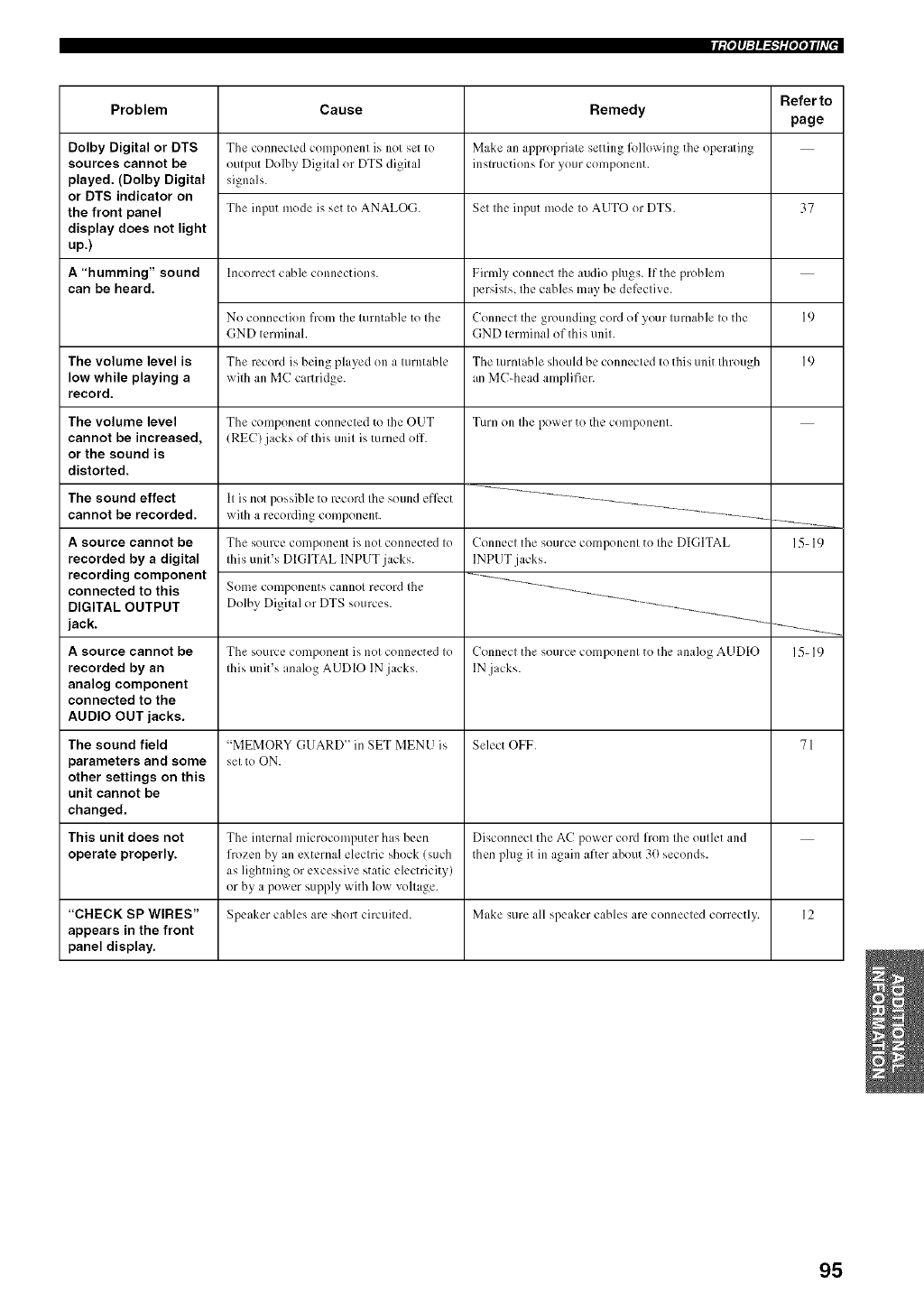
fip4q=l_'}i[qqih_{'
Problem
Dolby Digital or DTS
sources cannot be
played, (Dolby Digital
or DTS indicator on
the front panel
display does not light
up.)
A"humming" sound
can be heard.
The volume level is
low while playing a
record.
The volume level
cannot be increased,
or the sound is
distorted.
The sound effect
cannot be recorded.
A source cannot be
recorded by a digital
recording component
connected to this
DIGITAL OUTPUT
jack.
A source cannot be
recorded by an
analog component
connected to the
AUDIO OUT jacks.
Cause
The connected component is not set to
output Dolby Digital or DTS digital
signals.
The input mode is set to ANALOG.
Incorrect cable connections.
No connection from the turntable to the
GND terminah
The recoM is being played on a turntable
with all MC cartridge.
The component connected to the OUT
(REC) jacks of this unit is turned off.
It is not possible to record the sound efk.ct
with a recording component.
The source component is not connected to
this unit's DIGITAL INPUT jacks.
Sonle components cannot record the
Dolby Digital or DTS sources.
The source component is not connected to
this unit's analog AUDIO IN jacks.
Remedy
Make an appropriate setting lkdlox_ing the operating
instrllctions for your component.
Set the input mode to AUTO or DTS.
Firmly connect the audio plugs. If the problem
persists, the cables may be dek.ctive.
Connect the grounding cord of your turnable to tile
GND terminal of this unit.
The turntable should be connected to this unit through
an MC-head amplifier.
Turn on the power to the component.
Connect the source component to the DIGITAL
INPUT jacks.
Connect tile source component to tile anak>g AUDIO
lN jacks.
Referto
page
37
19
19
The sound field "MEMORY GUARD" in SET MENU is Select OFF. 71
parameters and some setto ON.
other settings on this
unit cannot be
changed,
This unit does not Tile internal micwcomlx=ter has bccn Disconnect tile AC power coM from tile outlet and
operate properly, frozen by an external electric shock (such then phlg it in again after about 3(1seconds.
as lightning or excessive static electricity)
or by a power supply with low voltage.
"CHECK SP WIRES" Speaker cables are short circuited. Make sure all speaker cables are connected correctly. 12
appears in the front
panel display.
15-19
15-19
95
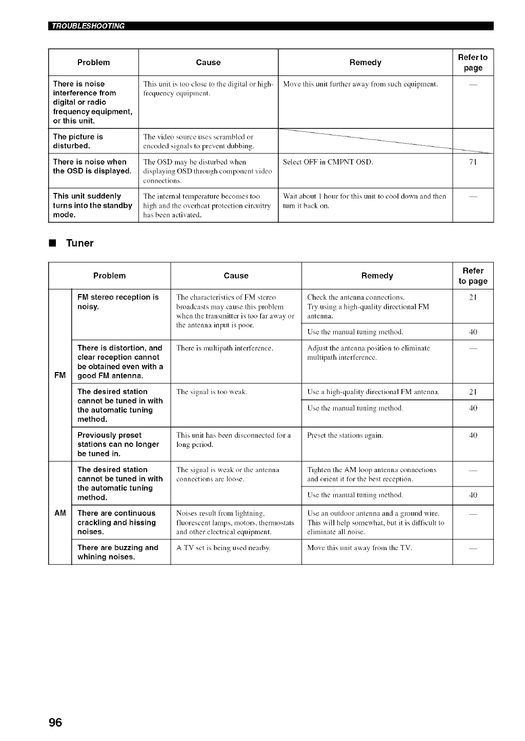
|lill_q:l_"lilqqih7 J
Problem
There is noise
interference from
digital or radio
frequency equipment,
or this unit.
Cause
This unit is too close to tile digital or high-
frequency eqciipment.
Remedy
Move this unit further a_ay from such equipment.
Referto
page
The picture is The vide() source uses scrambled or
disturbed, encoded signals to prevenl dubbing.
There is noise when The OSD may be disturbed when Select OFF in CMPNT OSD. 71
the OSD is displayed, disphlying OSD through component video
connections.
This unit suddenly The intern d temperature becomes too Wait about 1 hour l()r this unit to cool down and then
turns into the standby high and the overheat protection circuitry turn it back on.
mode. has been activated.
•Tuner
Refer
Problem Cause Remedy to page
FM stereo reception is 2I
noisy.
FM
There is distortion, and
clear reception cannot
be obtained even with a
good FM antenna.
The desired station
cannot be tuned in with
the automatic tuning
method.
The ch ir icteristics of FM stere()
broadcasts may cause this problem
when the transmitter is too far away or
the antenna input is poor.
Check the antenna connections.
Try using a high-quality directional FM
antenna.
Use the manual tuning method. 40
There is multipath interference. Ac[iust the antenna position to eliminate
multipath interference.
The signal is too weak. Use a high-quality directional FM antenna. 2 I
Use the mamlal tuning method. 40
Previously preset This unit has been disconnected lk)r a Preset the stations again. 40
stations can no longer h)ng period.
be tuned in.
Tile signal is weak or the antenna
connections are loose.
The desired station
cannot be tuned in with
the automatic tuning
method.
Tighten the AM loop antenna connections
and orient it for the best reception.
Use the manual tuning method. 4O
AM There are continuous Noises result from lightning, Use an outdoor antenna and a ground wire.
crackling and hissing fluorescent lamps, motors, thermostats This will help somewhaL but it is difficult to
noises, and other electrical equipment, eliminate all noise.
There are buzzing and A TV set is being used nearby. Move this unit away fiom the TV.
whining noises.
96
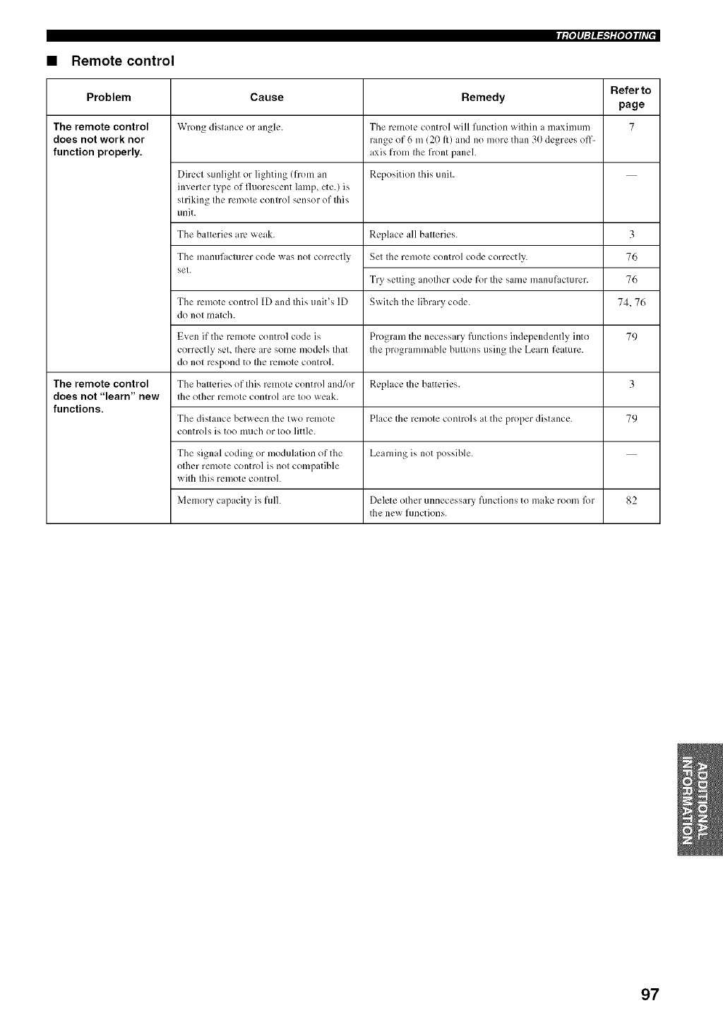
fip4q:l_=h'ilfqqi/t'{'
•Remote control
Refer to
Problem Cause Remedy page
The remote control Wrong distance or angle. The remote control _xill function within a maximum 7
does not work nor range of 6 m (20 It) and no more than 30 degrees off-
function properly, axis from the front paneh
Direct sunlight or lighting (from an Reposition this unit.
inverter type of fluorescent lamp, etc.) is
striking tile remote control sensor of this
unit.
The batteries arc weak.
The mantlfacttlrcr code was not correctly
set.
The remote control ID and this unit's ID
do not match.
Even if the remote control code is 79
correctly seL there are some models that
do not respond to the remote controh
The remote control The batteries of this remote control and/or 3
does not "learn" new the other remote control are too weak.
functions. The distance between the two remote 79
controls is too much or too little.
The signal coding or modulation of the
other remote control is not compatible
with this remote controh
Memory capacity is fulh Delete other unnecessary functions to make room lbr 82
the new functions.
Replace all batteries.
Set the remote control code correctly.
Try setting another code for the same manufacturer.
Switch the library code.
Program the necessa W functions independently into
the programmable buttons using the Learn feature.
Replace the batteries.
Place tile remote controls at the proper distance.
Learning is not possible.
3
76
76
74.76
97
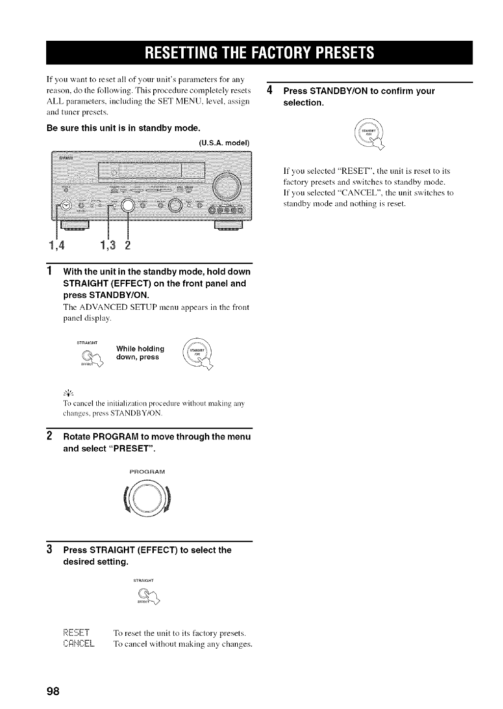
If you want to reset all of your unit's parameters for any
reason, do the following. This procedure completely resets
ALL parameters, including the SET MENU, level, assign
and tuner presets.
Be sure this unit is in standby mode.
(U.S.A. model)
4Press STANDBY/ON to confirm your
selection.
If you selected "RESET", the unit is reset to its
factory presets and switches to standby mode.
If you selected "CANCEL", the unit switches to
standby mode and nothing is reset.
1,4 1,3 2
With the unit in the standby mode, hold down
STRAIGHT (EFFECT) on the front panel and
press STANDBY/ON.
The ADVANCED SETUP n]eml appears in the front
panel display.
SS"rtAiGHT While holding
down, press
To cancel the initializatior'_ procedure without making any
changes, press STANDB Y/ON.
Rotate PROGRAM to move through the menu
and select "PRESET".
PROGRAM
3 Press STRAIGHT (EFFECT) to select the
desired setting.
i:::,_1::',::,"i:::""i"
1',,i,,,, ,,,,ii,,,, i To reset the unit to its factory presets.
To cancel without making any changes.
98
•Dolby Digital
Dolby Digital is a digital surronnd sonnd system that gives
you completely independent nmlti-channel audio. With 3
front channels (left, center, and right), and 2 surronnd
stereo channels, Dolby Digital provides 5 fidl-range audio
channels. With an additional channel especially for bass
effects, called LFE (low frequency effect), the system has
a total of 5.1 -channels (LFE is counted as 0.1 channel). By
using 2-channel stereo for the surronnd speakers, more
accurate moving sound effects and surronnd sound
environment are possible than with Dolby Surround. The
wide dynamic range (from maximum to nlinimum
volume) reproduced by the 5 fill-range channels and the
precise sound orientation generated using digital sound
processing provide listeners with previously unheard of
excitement and realism.
With this unit, any sound enviromnent from monaural up
to a 5.1 -channel configuration can be freely selected for
your enjoyment.
•Dolby Digital EX
Dolby Digital EX creates 6 full-bandwidth output
channels from 5.l-channel sources. This is done using a
matrix decoder that derives 3 surround channels from the
2 in the original recording. For the best results, Dolby
Digital EX should be used with movie sound tracks
recorded with Dolby Digital Surround EX. With this
additional channel, you can experience more dynamic and
realistic moving sound especially with scenes with
"flyover" and "fly-around" effects.
•Dolby Pro Logic II
Dolby Pro Logic lI is an improved technique nsed to
decode vast numbers of existing Dolby Surround
software. This new technology enables a discrete 5-
channel playback with 2 tYont left and right channels, 1
center channel, and 2 surround left and right channels
(instead of only 1 surround channel for conventional Pro
Logic technology). Music and Game modes are also
available for 2-channel sources in addition to the Movie
mode.
•Dolby Pro Logic IIx
Dolby Pro Logic lIx is a ne'a, technology enabling discrete
multi-channel playback from 2-channel or nmlti-channel
sources. There is a Music mode for music, a Movie mode
for movies and a Game mode for games.
•Dolby Surround
Dolby Snrround uses a 4 channel analog recording system
to reproduce realistic and dynamic sound effects: 2 front
left and right channels (stereo), a center channel for dialog
(monaural), and a surround channel for special sound
effects (monaural). The surround channel reproduces
sound within a narrow frequency range.
Dolby Surround is widely nsed with nearly all video tapes
and laser discs, and in many TV and cable broadcasts as
well. The Dolby Pro Logic decoder built into this unit
employs a digital signal processing system that
automatically stabilizes the volume on each channel to
enhance moving sound effects and directionality.
•DTS 96/24
DTS 96/24 offers an nnprecedented level of audio quality
for multi-channel sound on DVD-Video, and is fully
backward-compatible with all DTS decoders. "96" refers
to a 96 kHz sampling rate (compared to the typical 48 kHz
sampling rate). "24" refers to 24-bit word length. DTS 96/
24 offers sound quality transparent to the original 96/24
master, and 96/24 5. l-channel sound wdth fill-quality fill-
motion video for nmsic programs and motion picture
soundtracks on DVD-video.
•DTS (Digital Theater Systems)
Digital Surround
DTS digital surround "a,as developed to replace the analog
soundtracks of movies with a 6-channel digital sound
track, and is now rapidly gaining popularity in movie
theaters around the workt. Digital Theater Systems Inc.
has developed a home theater system so that you can
enjoy the depth of sound and natural spatial representation
of DTS digital surround in your home. This system
produces practically distortion-t_ee 6-channel sound
(technically, a left, right and center channels, 2 surround
channels, pins an LFE 0.1 channel as a subwoofer, for a
total of 5.l-channels). The unit incorporates DTS-ES
decoder that enables 6.1 - channel reproduction by adding
the surround back channel to existing 5. l-channel tUrmat.
•Nee:6
Neo:6 decodes the conventional 2-channel sources for 6
channel playback by the specific decoder. It enables
playback with the fill-range channels with higher
separation jnst like digital discrete signal playback. Two
modes are available; "Music mode" for playing nmsic
sources and "Cinema mode" for movies.
99
|qllib'b',_ llll'
•CINEMA DSP
Since the Dolby Surround and DTS systems xx,ere
originally designed for use in movie theaters, their effect
is best felt in a theater having many speakers and designed
f%r acoustic effects. Since home conditions, such as room
size, wall material, number of speakers, and so on, can
differ so widely, it's inevitable that there are differences in
the sound heard as well. Based on a wealth of actually
measured data, YAMAHA CINEMA DSP uses
YAMAHA original sound field technology to combine
Dolby Pro Logic, Dolby Digital and DTS systems to
provide the visual and audio experience of movie theater
in the listening room of your own home.
•SILENT CINEMA
YAMAHA hits developed a natural, realistic sound effect
DSP algorithm for headphones.
Parameters for headphones have been set for each sound
field so that accurate representations of all the sound field
programs can be enjoyed on headphones.
•Virtual CINEMA DSP
YAMAHA has developed a Virtual CINEMA DSP
algorithm that allows you to enjoy DSP sound field
surround effects even without any surround speakers by
using virtual surround speakers.
It is even possible to enjoy Virtual CINEMA DSP using a
minimal two-speaker system that does not include a center
speaker.
•ITU-R
ITU-R is the radio communication sector of the ITU
(International Telecommunication Union). ITU-R
recommends a standard speaker placement which is used
in many critical listening rooms, especially for mastering
purposes.
•LFE0.1 channel
This channel is for the reproduction of low bass signals.
The frequency range for this channel is 20 Hz to 120 Hz.
This channel is counted as 0.1 because it only enforces a
low frequency range compared to the full-range
reproduced by the other 516channels in Dolby Digital or
DTS 5.116.1-channel systems.
•PCM (Linear PCM)
Linear PCM is a signal format under "a,hich an analog
audio signal is digitized, recorded and transmitted without
using any compression. This is used as a method of
recording CDs and DVD audio. The PCM system uses a
technique for sampling the size of the analog signal per
very small unit of time. Standing for "pulse code
modulation", the analog signal is encoded as pulses and
then modulated for recording.
•Sampling frequency and number of
quantized bits
When digitizing an analog audio signal, the number of
times the signal is sampled per second is called the
sampling frequency, while the degree of fineness when
converting the sound level into a numeric value is called
the number of quantized bits.
The range of rates that can be phtyed back is deternfined
based on the sampling rate, while the dynamic range
representing the sound level difference is determined by
the number of quantized bits. In principle, the higher the
sampling frequency, the wider the range of frequencies
that can be phtyed back, and the higher the number of
quantized bits, the more finely the sound level can be
reproduced.
100
•Component video signal
With tile component video signal system, tile video signal
is separated into the Y signal for the luminance and the Ps
and Pit signals for the chrominance. Color can be
reproduced more faithfidly with this system because each
of these signals is independent. The component signal is
also called the "color difference signal" because the
luminance signal is subtracted from the color signal.
A monitor with component input jacks is required in order
to use the component signal for output.
•Composite video signal
With the composite video signal system, the video signal
is composed of three basic elements of a video picture;
color, brightness and synchronization data. A composite
video jack on a video component transmits these three
elements combined.
•S-video signal
With the S-video signal system, the video signal normally
transmitted using a pin cable is separated and transmitted
as the Y signal for the luminance and the C signal for the
chrominance through the S-video cable. Using the
S VIDEO jack eliminates video signal transmission loss
and allows recording and playback of even more beautiful
images.
101
AUDIO SECTION
•Minimum RMS Output Pm_erlbr FronL Ccntcr, Surround,
Surround back
20 Hz to 20 kHz_ 0.0(V,_THD_ 8 L) .................................... 100 W
• Maximum Power iEIAJ)
[China, Korea and General models]
1 kHz, 10% THD, 8 £2 ....................................................... 140 W
• Dynumic Power (IHF)
8/6/4/2 £_ ....................................................... 135/170/200/245 W
•DIN Standard Output Power [U.K. and Europe models]
1 kHz, 0.7q_ THD, 4 £_ ...................................................... 150 W
• IEC Output Power [UK. and Europe models]
1 kHz, 0.06% THD, 8 L) .................................................... 110 W
• Damping Factor (IHF)
20 Hz to 20 kHz, 8 £) ................................................ 120 or more
•Frequency Response
CD terminal to Front L/R ..................... 10 Hz to 100 kHz, 3 dB
• Total Harmonic Distortion
PHONO to REC OUT i211Hz to 2(}kHz, 1 V) ...... 0.02% or less
CD, etc. to Front L/R
120 Hz to 20 kHz, 5/) W, 8 £_) ............................ 0.06% or less
• Signal to Noise Ratio (IHF-A Network)
Phono 15mV) to REC OUT
[UK., Europe and Australia models] .................... 81 dB or more
[Other models] ...................................................... 86 dB or more
CD 125/) mV) to Front L/R. Efk.ct Off ............... 1/10dB or more
• Residual Noise (IHF-A Network)
Front L/R .............................................................. 150 pV or less
• Channel Separation ( 1 kH//10 kHz)
PHONO (shorted) to Front L/R ................. 60 dB/55 dB or more
CD i5.1 k£_terminated) to Front L/R ........ 60 dB/45 dB or more
• Tone Control (Front L/R)
BASS Boost/Cut ..................................................... _+6dB/50 Hz
BASS Turnover Frequency ............................................... 35//Hz
TREBLE BoosffCut .............................................. _+6dB/20 kHz
TREBLE Turnover Frequency ......................................... 3.5 kHz
• Phones Output ......................................................... 15(}mV/100 £2
• Input Sensitivitv/lnput hnpedance
PHONO ................................................................. 2.5 mV/47 k_
CD, etc................................................................. 200 mV/47 k£_
MULTI CH INPUT .............................................. 200 mV/47 k£_
• Output Level/Output hnpedance
REC OUT ............................................................ 200 mV/1.2 k£_
PRE OUT .................................................................... 2 VII.2 k£_
SUB WOOFER .......................................................... 4 VII.7 k[2
ZONE 2 OUTPUT
[U.S.A., Canada, Australia and
Europe models] ................................................... 200 mV/1.2 k[2
VIDEO SECTION
• Video Signal Type ........................................................ PAL/NTSC
• Signal to Noise Ratio ............................................... 5(/dB or more
• Frequency Response (MONITOR OUT)
Composite, S-video ................................ 5 Hz to 10 MHz, 3 dB
Component ............................................. 5 Hz to 60 MHz, 3 dB
FM SECTION*
•Tuning Range
IU.S.A. and Canada models] ......................... 87.5 to 107.9 MHz
[General model] ....................... 87.5187.50 to 108.01108.00 MHz
[Other models] ........................................... 87.50 to 108.00 MHz
• Usable Sensitivity (IHF) ...................................... 1.0 pV (I 1.2 dBf)
• Signal to Noise Ratio ilHF)
Mono/Stereo ............................................................ 76 dB/70 dB
• Harmonic Distortion (I kHz)
Mono/Stereo .............................................................. 0.2%K}.3%
• Stere()Separation (1kHzJ ...................................................... 42 dB
• Frequency Response ........................ 20 Hz to 15 kHz, +0.5, 2 dB
AM SECTION*
• Tuning Range
IU.S.A. and Canada models] ............................ 530 to 1710 kHz
[Gener d model] ................................ 5301531 to 1710/1611 kHz
[Other models] ................................................... 531 to 1611 kHz
• Usable Sensitivity ........................................................... 300 ]lV/m
GENERAL
• Po_er Supply
[U.S.A. and Canada models] ............................ AC 120 V, 60 Hz
[Australia model] .............................................. AC 240 V, 5(}Hz
[China model] ................................................... AC 220 V, 50 Hz
[Korea model] ................................................... AC 220 V, 60 Hz
[U.K. and Europe models] ................................ AC 230 V, 50 Hz
[General model] ............. AC 1101120/2201230_40 V, 50160 Hz
• Power Consumption
[U.S.A. and Canada models] ............................... 400 W1500 VA
[Other models] .................................................................. 440 W
• Standby Power Consumptkm .................................... 0.1 W or less
• AC Outlets
[U.K. and Australia models] ............. 1(Total 100 W maximum)
[U.S.A., Canada md China models]... 2 ITotal 100 W maximum)
[Europe aM General models] ............... 2 (Total 5(}W maximum)
• Dimensions (W x H x D) ................................. 435 x 171 x 420 mm
(17-118" x 6-3/4" x 16-112")
• Weight ............................................................ 12.5 kg (27 lbs 9 oz)
'_Except Europe model
102

¢_._2005 YAMAHA CORPORATION All Fights reserved
YAMAHA ELECTRONICS CORPORATION, USA 6660 ORANGETHORPE AVE., BUENA PARK, CALIF. 90620, U.S.A.
YAMAHA CANADA MUSIC LTD. 135 MILNER AVE., SCARSOROUGH, ONTARIO M1S 3R1, CANADA
YAMAHA ELECTRONIK EUROPA G.m.b.H. SIEMENSSTR. 22-34, 25462 RELLINGEN BEI HAMBURG, GERMANY
YAMAHA ELECTRONIQUE FRANCE S.A. RUE AMBROISE CROIZAT BP70 CROISSY-BEAUBOURG 77312 MARNE-LA-VALLEE CEDEX02, FRANCE
YAMAHA ELECTRONICS (UK) LTD. YAMAHA HOUSE, 200 RICKMANSWORTH ROAD WATFORD, HERTS WD18 7GQ, ENGLAND
YAMAHA SCANDINAVIA A.S. J A WETTERGRENS GATA 1, BOX 30053, 400 43 V,_STRA FROLUNDA, SWEDEN
YAMAHA MUSIC AUSTRALIA PTY, LTD. 17-33 MARKET ST., SOUTH MELBOURNE, 3205 VIC., AUSTRALIA
YAMAHA CORPORATION
Printed in Malaysia c WE59930
