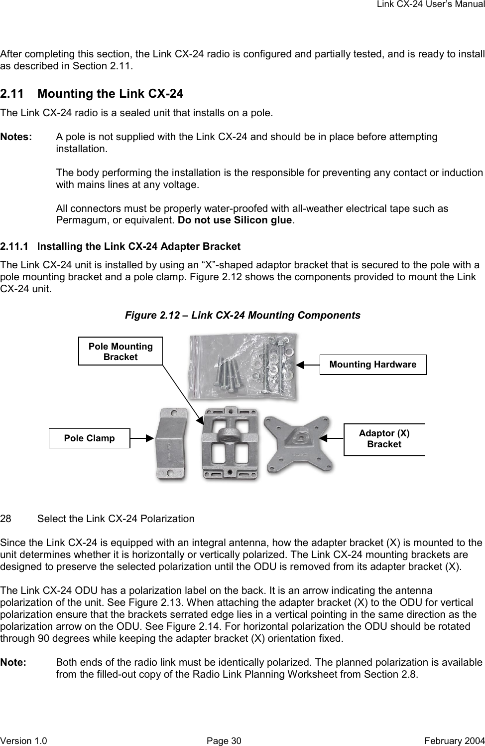
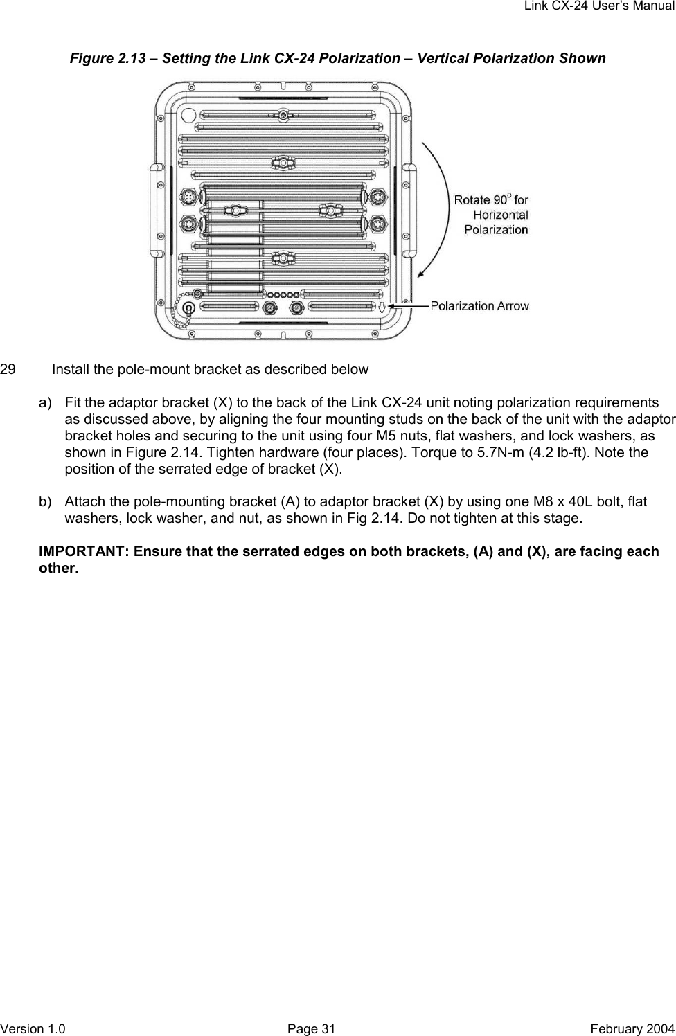
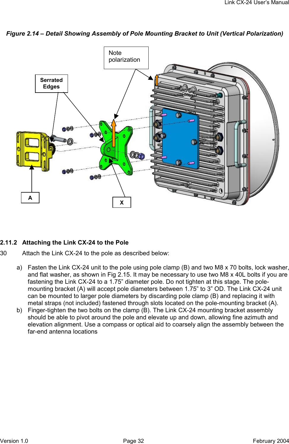
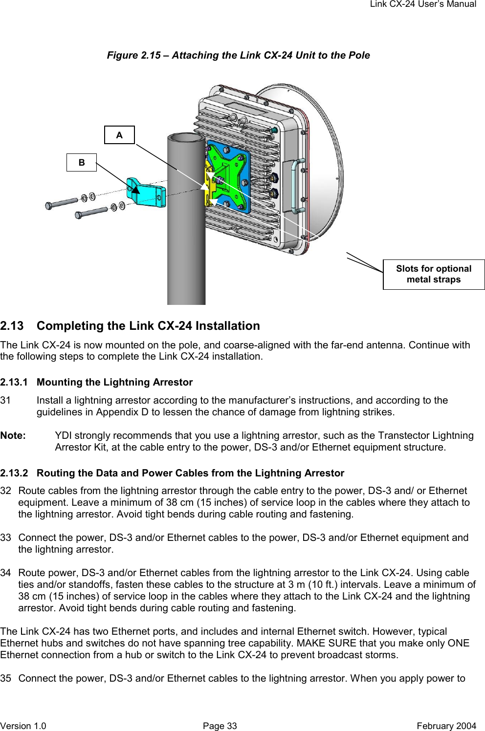
YDI Wireless CX-DS3-ETH-24 Point to Point 24GHz Microwave Radio User Manual TABLE OF CONTENTS
YDI Wireless Point to Point 24GHz Microwave Radio TABLE OF CONTENTS
UserManual.wiki
>
YDI Wireless
>
CX-DS3-ETH-24 User Manual
>
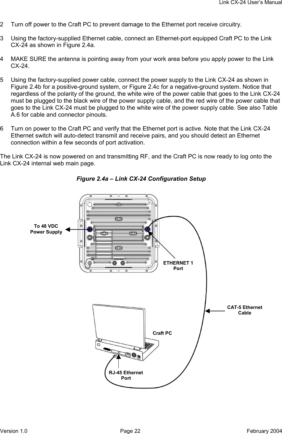
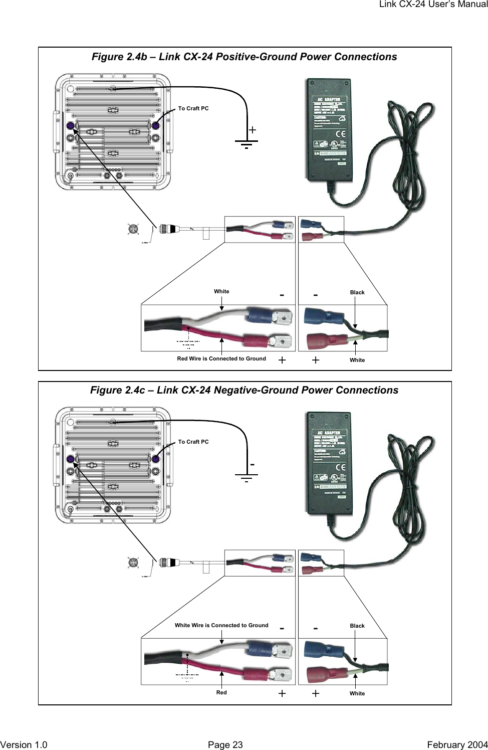
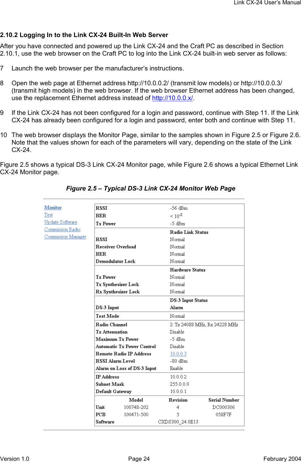
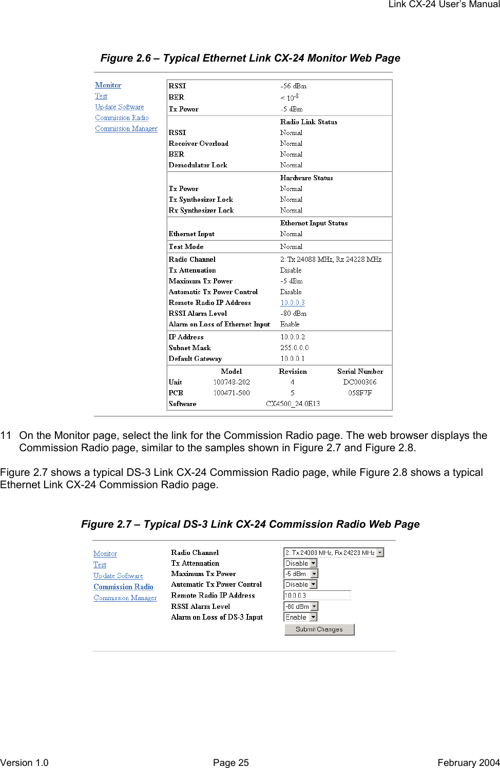
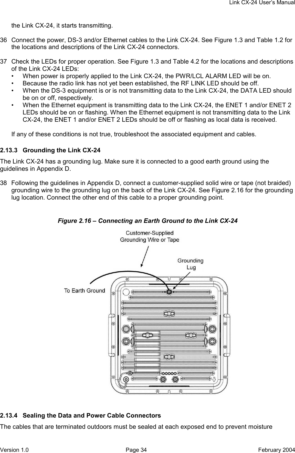
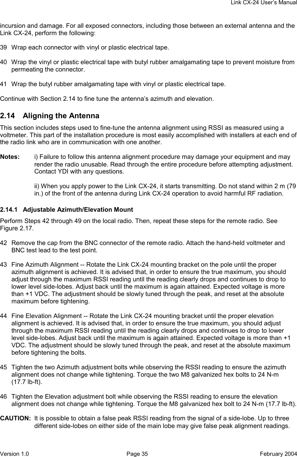
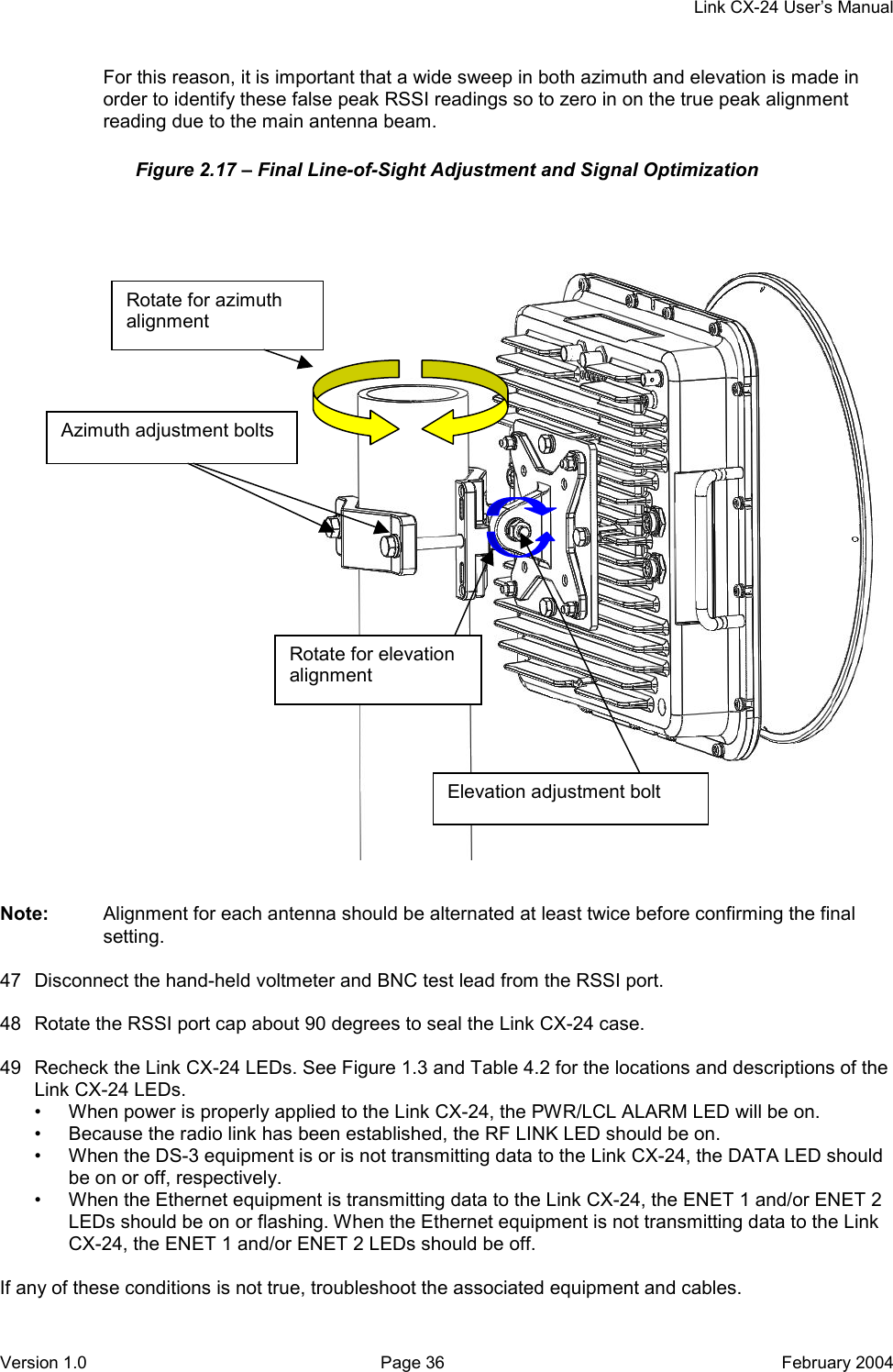
Manual Part 1
Contents
1.
Manual Part 1
2.
Manual Part 2
Manual Part 1
Navigation menu
Upload a User Manual
Namespaces
Wiki Guide
HTML
PDF
Info
Views
User Manual
Discussion / Help
Navigation