YDI Wireless MB-HP Outdoor Transmitter User Manual Marquee Bridge ISM vED3
YDI Wireless Outdoor Transmitter Marquee Bridge ISM vED3
Contents
Manual
Marquee Bridge™
PRELIMINARY Quick Start Guide
MNL-500265-001 – Rev ED3 1 Jul 2004
Introduction
The Marquee Bridge (MB) is a complete 5 GHz wireless
point-to-point (p-p) or point-to-multipoint (p-mp) system
that links two Ethernet LANs together. It consists of two
high-gain directional antennas and a pair of OFDM
radios in a rugged outdoor enclosure. They connect to
the LAN's Ethernet Switch on each end with an outdoor-
rated Ethernet cable ordered separately. It is ideal for
connecting two office LANs together, or for linking a
WIPOP site to an Internet backbone. The Marquee
Bridge uses the YDI-Fi software which supports VLAN
bridging (802.1q protocol).
The Marquee Bridge will accommodate virtually an
unlimited number of client MAC addresses on each side
of the link. With 5 non-overlapping channels available,
up to 5 bridges can be co-located at a site.
The Marquee Bridge is available in four versions:
• Standard version with an integrated one-foot flat
panel antenna (MB-INT-ST) for operation in the
UNII Band II (5.250 – 5.350 GHz)
• Standard version with an N-type connector for an
external antenna (MB-EXT-ST) for operation in the
ISM Band (5.725 – 5.850 GHz)
• High Power version with an integrated one-foot flat
panel antenna (MB-INT-HP) for operation in the
ISM Band (5.725 – 5.850 GHz)
• High Power version with an N-type connector for an
external antenna (MB-EXT-HP) for operation in the
ISM Band (5.725 – 5.850 GHz)
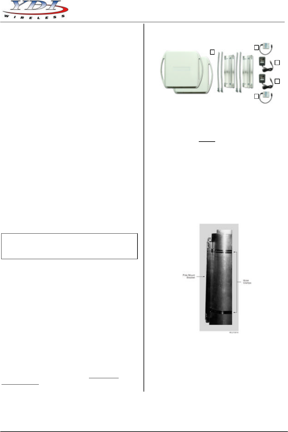
Marquee Bridge Kit Contents
1. Two outdoor radios with mounting hardware
2. Two Cat 5 DC Power Injectors (surge protected
Power Injectors are available as an option)
3. Two 110/240 VAC to 48 VDC power supplies
4. Windows -based YDI AP Manager software
5. MB-INT – two radios with built-in 23 dBi one foot
FP antenna
MB-EXT – two radios with RF connector for
external antenna,
two 3 foot low-loss coaxial cables, and
two high-gain directional antennas
YDI EtherAnt outdoor Ethernet cables must be ordered
separately. Available lengths are 50, 100, 200, or 300 ft.
The Marquee Bridge is intended for professional
installation only. Please review the entire manual before
powering up or deploying these units.
Figure 1 – Marquee Bridge Kit Contents
Installation
NOTE: All connectors must be properly water-proofed
with all-weather electrical tape, Permagum, or
equivalent. Do not use Silicon glue.
The Marquee Bridge radio unit is installed by means of
a pole mount adaptor bracket that is secured to the pole
using two metal hose type clamps. Figure 1 shows the
hardware provided to mount the outdoor RF Unit.
1. Install the outdoor unit pole mount adaptor bracket
using the supplied metal hose type clamps (see
Figure 2).
Figure 2 – Detail Showing Outdoor Unit Pole Mount
Bracket
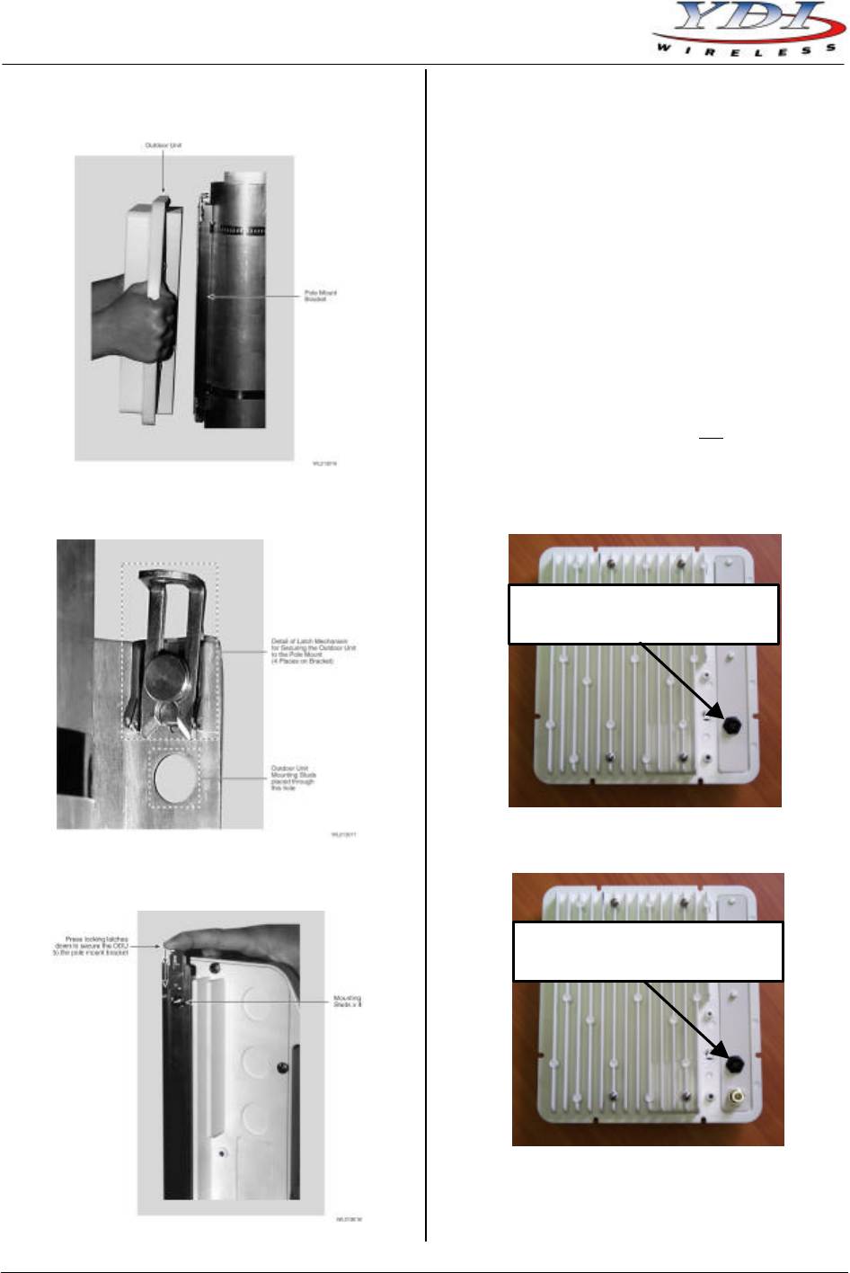
2. Align the four mounting studs on the outdoor unit
with the bracket holes (see Figure 3) and secure to
the bracket by pushing down the latches as shown
in Figures 4a and 4b.
1
2
3
2
3
Note:
This manual applies to the Marquee Bridge
versions that operate in the ISM Band (MB-EXT-
ST,
MB-INT-HP, and MB-EXT-HP).
Marquee Bridge™
Quick Start Guide PRELIMINARY
Jul 2004 2 MNL-500265-001 – Rev ED3
Figure 3 – Attaching the Marquee Bridge Outdoor
Unit to the Pole Mount Bracket
Figure 4a – Latching Bracket to Pole Mount
Figure 4b – Securing the Latches to the Pole Mount
Bracket
3. Ensuring that there is no DC power applied to the
DC Power Injector, plug the round connector of the
outdoor Ethernet cable into the rear jack of the unit
(Fig. 5a for an MB-INT, or Fig. 5b for an MB-EXT),
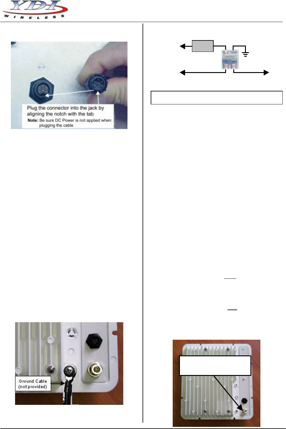
making sure the notch is correctly aligned with the
tab on the jack as shown in Figure 6, then turn the
round locking nut clockwise as you push in until it
securely fastens onto the jack.
WARNING: Please verify that the round connector
is properly plugged into the rear jack of the antenna
prior to connecting DC power because it is possible
to push it in the wrong way if enough force is used.
If DC Power is applied while you are attempting to
insert the round connector into the jack, it is
possible that, as you rotate the plug in an effort to
find the key, DC power pins will momentarily touch
the Ethernet pins. If this happens the Ethernet
circuitry on the board will be damaged. Any
harm caused by this action will not be covered by
the factory warranty and will be a billable repair.
Figure 5a – Connecting the Outdoor Ethernet Cable
to an MB-INT
Figure 5b – Connecting the Outdoor Ethernet Cable
to an MB-EXT
Plug Round Connector of the
Outdoor Ethernet Cable Here
Pl
ug Round Connector of the
Outdoor Ethernet Cable Here
Marquee Bridge™
PRELIMINARY Quick Start Guide
MNL-500265-001 – Rev ED3 3 Jul 2004
Figure 6 – Plugging the Round Connector
4. Attach the other end of the outdoor Ethernet cable
to the Cat 5 DC Power Injector at port RJ-45
labeled “To ANT.”
NOTE: The Cat 5 DC Power Injector is not in a
waterproof enclosure and must be protected
from the weather. It can be permanently
mounted to a surface using the double stick
tape found on the back of it.
5. Connect the Ethernet cable labeled “To PC or
Router” from the Cat 5 DC Power Injector to your
router, switch or hub. If you connect to a computer
or PC, a crossover cable or adapter will be needed.
6. If your unit is placed on a non-metal pole or
structure, install a #6 AWG insulated ground cable
(not provided) to the ground connector in the back
of the radio as shown in Figure 7. Use a self-
threading screw and a flat washer to fasten the
earth lug. This provides safeguard against lightning.
For maximum protection, YDI also recommends the
use of its optional surge protected DC Injector
available from your YDI dealer (part No. 304-
800620-002). This DC Injector has an additional
wire to be connected to ground as shown on Fig. 8.
Figure 7 – Detail Showing Ground Cable Connection
(this provides maximum lightning protection)
Figure 8 – Installation of the Optional YDI Surge
Protected DC Injector
7. Depending upon the type of unit that you have,
follow instructions (a) or (b):
(a) If you have an MB-INT version, the Marquee
Bridge contains the antenna. Plug the AC
Adapter into an AC outlet and connect it to the
“DC Power” jack on the Cat 5 DC Power
Injector. Perform antenna alignment
procedures at both sites. Proper antenna
alignment is crucial for the correct operation of
the Marquee Bridge system and should only be
accomplished by experienced professionals.
After that your installation is complete.
(b) If you have an MB-EXT version, plug the
antenna coaxial cable into the N-type female
connector of the unit as shown in Figure 9.
Plug the AC Adapter into an AC outlet and
connect it to the “DC Power” jack on the Cat 5
DC Power Injector. Perform antenna alignment
procedures at both sites. Proper antenna
alignment is crucial for the correct operation of
the Marquee Bridge system and should only be
accomplished by experienced professionals.
After that your installation is complete.
WARNING: The MB-EXT must be operated with a
proper 5 GHz antenna or microwave terminator
plugged into the N-type female jack of the unit.
Operating the unit with nothing connected to the
antenna jack may result in damage to the TX
section of the unit which will not be covered by the
factory warranty and will be a billable repair.
Figure 9 – Connecting the Antenna Coaxial Cable to
an MB-EXT
Plug Antenna Coaxial
Cable Here
AC Power
RJ
-
45 Ethernet Connector
To Switch, Router or PC
To MB
Power
Supply
YDI Surge Protected DC
Injector
Ground
Wire
NOTE:
The regular DC injector supplied with your kit is connected the same
way but it does not have a ground wire
Marquee Bridge™
Quick Start Guide PRELIMINARY
Jul 2004 4 MNL-500265-001 – Rev ED3
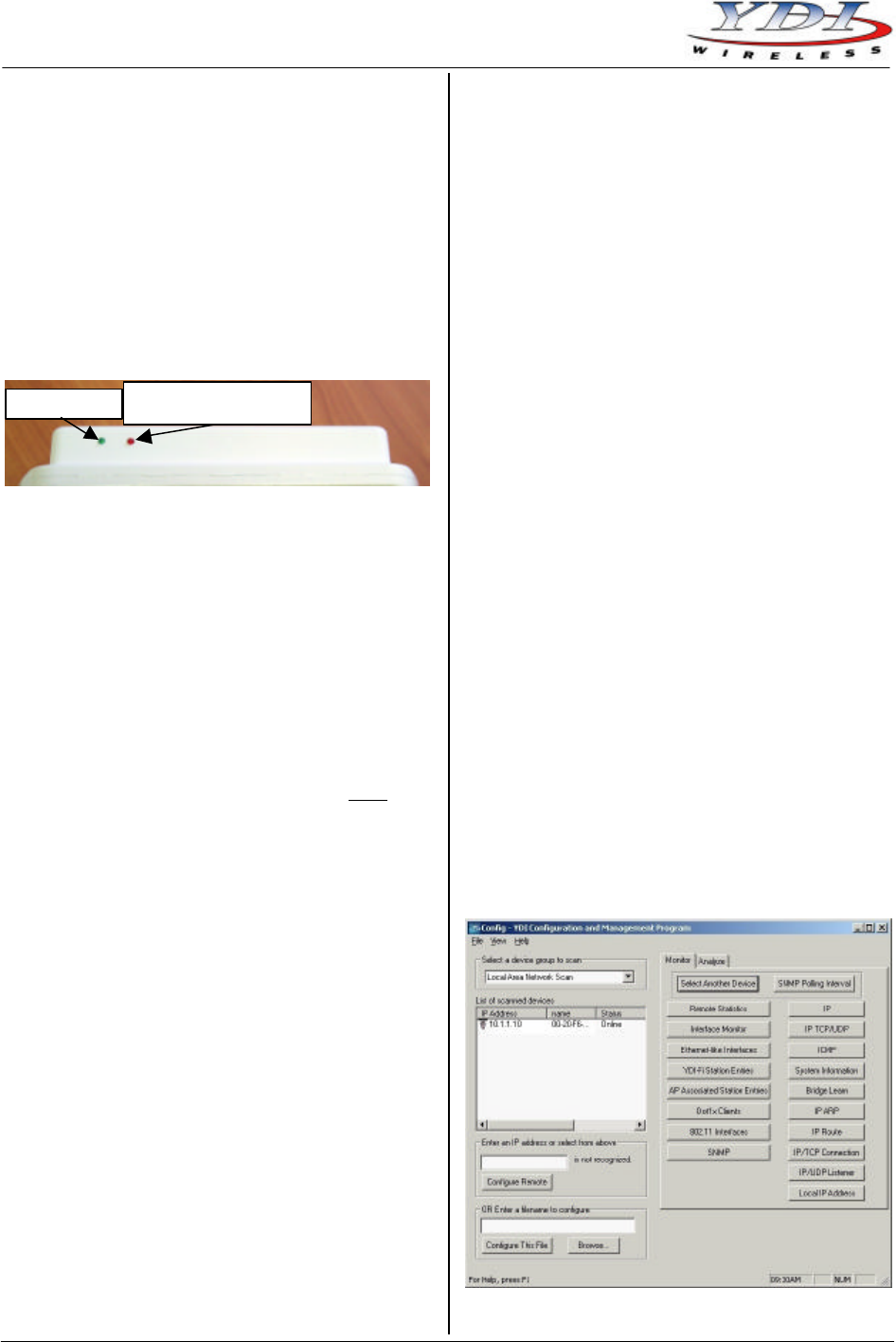
LEDs
Depending on the model, one or two LEDs are present
on the front of the Marquee Bridge (Figure 10):
–ST Models:
• The Green LED is steady on when power is applied
–HP Models:
• The Green LED flashes when the Marquee Bridge
is in receive mode (steady on when idle)
• The Red LED flashes when the Marquee Bridge
transmits data
Figure 10 – Marquee Bridge LEDs
Installing the Management Software
The Windows -based YDI AP Manager software can be
installed on a PC or workstation running Windows
98/ME, 2000, NT, or XP. This software has a GUI
(Graphical User Interface), which makes it easy to use.
The program allows you to locally or remotely perform
the following procedures:
• Display a list of units running on the local network
• Display and edit the current configuration of the
units
• Save and load configurations
IMPORTANT: Your Marquee Bridge units must be
on the same subnet as the computer with the YDI AP
Manager installed, or have a routable IP address, in
order to access it. If not, you will get a status of Offline
for the unit (see the Status column in Figure 11) even if
the LEDs show activity. To configure the units, change
the IP address of your computer to a 10.1.1.x sub-net.
Once you have access to the unit, you can then assign
a new IP address to it by clicking on the Setup tab and
IP Host button.
Note that the YDI AP Manager program is also used to
manage AP-Plus units. Therefore you will see many
grayed out options, features and settings. These only
become available when you are connected to an AP-
Plus, Orinoco AP, or router that has all these features
available.
To install the YDI AP Manager in Windows, insert the
YDI CD-ROM included in the AP-Plus kit into the
appropriate drive of your computer. Using your
Windows Explorer, open the directory \Management
Software\YDI AP Manager and run the Set Up program
ydi_ap.exe. Simply follow the instructions on the screen
which will guide you through the entire process. After
completing the YDI AP Manager installation, you are
ready to configure your system.
NOTE: For detailed information about the YDI AP
Manager, please refer to the documentation in
your CD ROM. Also, an online help is available
by pressing F1 or clicking Help-> Index from
the main screen.
Configuring the Marquee Bridge
The Marquee Bridge is shipped from factory pre-
configured for bridging operation and with the proper
transmit power settings. The two units are set with the
following default IP addresses:
10.1.1.10
and
10.1.1.11
The default read/write password is public.
Some of the parameters that you may need to change
are the following:
• IP addresses
• Read/Write password
• Radio frequency channel
1. Connect a crossover Ethernet cable from the Cat 5
DC Power Injector to your computer or PC.
2. Open the directory where the manager program
has been installed (the default is \Program
Files\YDI\AP Manager). Run the program AP
Manager.exe.
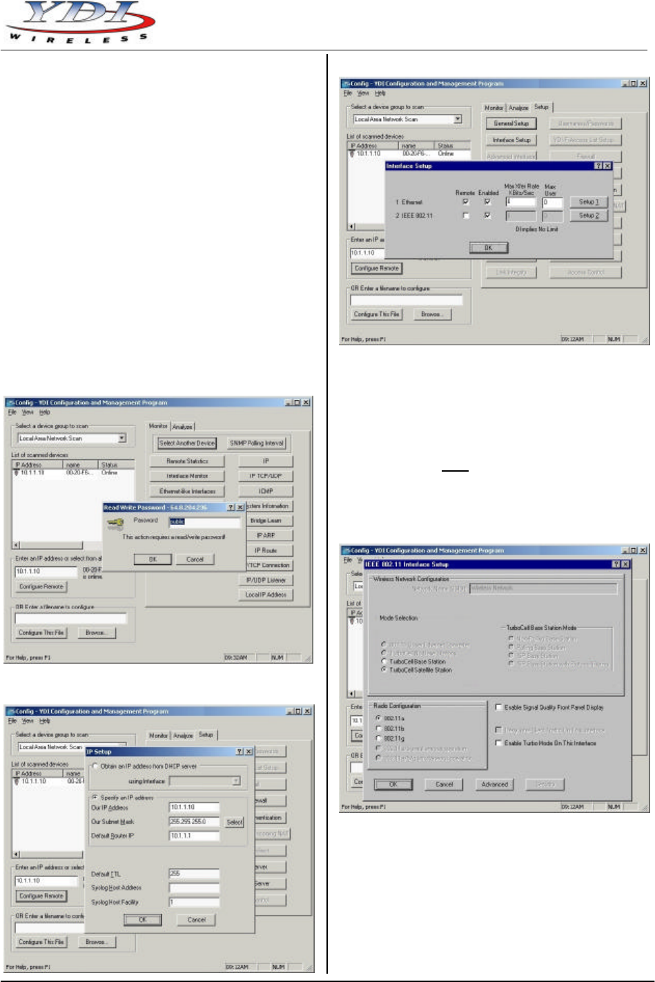
3. The Main Screen shown in Figure 11 appears. To
scan for devices on the network, place the cursor in
the List of Scanned Devices text box and right-click
the mouse. A Re-scan local network button will
appear. Click on the button. A list of devices will
appear.
Figure 11 – YDI AP Manager Main Screen
Green LED)
Red LED
(Not Present in –ST models)
Marquee Bridge™
PRELIMINARY Quick Start Guide
MNL-500265-001 – Rev ED3 5 Jul 2004
4. Click on the device you wish to configure. The
selected device IP address will appear in the text
box above the Configure Remote button
(alternatively, you can enter the IP address of the
Marquee Bridge unit). Click this button.
5. A Read/Write Password text box will appear (see
Figure 12). The default password is public. Click the
OK button. It is suggested that you change the
password later, write it down and keep it in a safe
place.
6. After you login successfully, the Setup screen
appears. Click on the IP Host button. The IP Setup
screen appears (see Figure 13). Enter the IP
Address, Subnet Mask, and Default Router IP
Address. Click OK.
7. On the Setup screen, click on the Interface Setup
button. The corresponding screen appears (see
Figure 14).
Figure 12 – Read/Write Password Screen
Figure 13 – IP Setup Screen
Figure 14 – Interface Setup Screen
8. Click on Setup 2. The 802.11 Setup screen appears
(see Figure 15). Select the type of Station this
Marquee Bridge is going to be. In a p-p
configuration, one unit must be Base and the other
must be Remote (Satellite). In a p-mp
configuration, one unit must be Base and all the
others must be Remote (Satellite). Radio
Configuration must be set to 802.11a. The Base
station should be set for Polling Base Station.
Leave the rest of the buttons unchanged.
Figure 15 – 802.11 Setup Screen
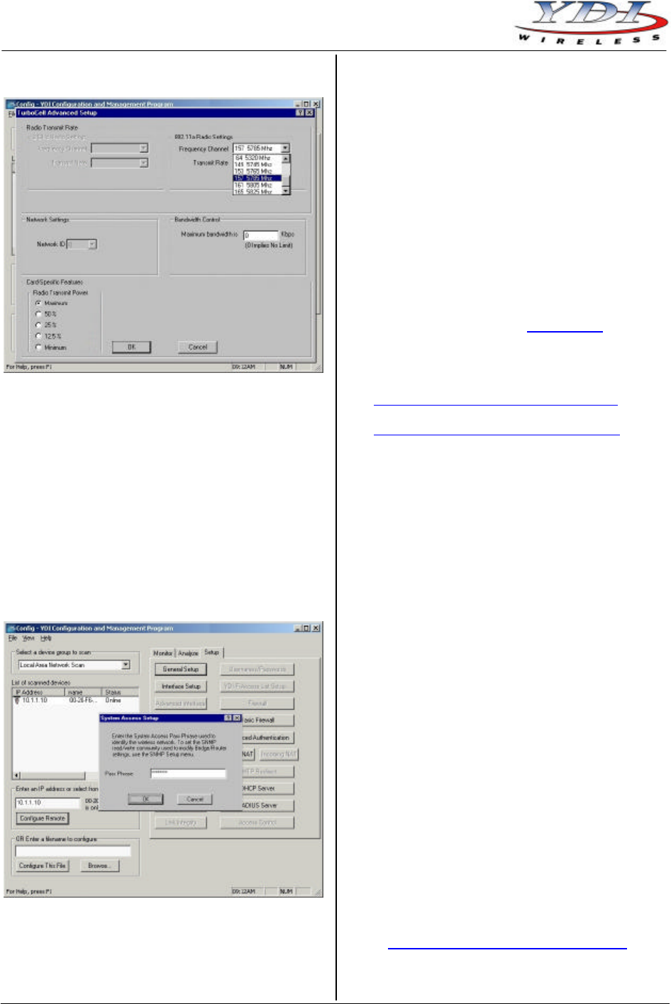
9. Click the Advanced button. The corresponding
screen appears (see Figure 16). Select a
Frequency Channel from the pull down menu box.
All units must be configured with the same value.
Marquee Bridge™
Quick Start Guide PRELIMINARY
Jul 2004 6 MNL-500265-001 – Rev ED3
Figure 16 – 802.11 Advanced Setup Screen
10. The Marquee Bridge is optimized for a transmit rate
of 36 Mbps and the transmit power is preset from
factory with the proper value.
NOTE: Make sure the output power is set to 50%
when using a sector antenna (see Table 1).
11. Click OK. Click OK again.
12. Click the System Access button. The corresponding
screen appears (see Figure 17). Enter a Pass
Phrase to identify the wireless network. All units
must be configured with the same value. Click OK.
Figure 17 – System Access Setup Screen
13. Go to File and click Save Config: this will save the
new settings.
14. After the Marquee Bridge is finished saving its
configuration, exit the YDI AP Manager program.
The Marquee Bridge is ready to use. Refer to the
online help for complete instructions on setting up
other features in the unit.
Technical Support
Your primary source of assistance is the dealer from
which you purchased this product. The YDI support staff
should only be contacted directly if you purchased this
product directly from YDI.
NOTE: Before you contact Technical Support, please
make sure that you have read and thoroughly
understood all instructions outlined on this
manual.
YDI Wireless Tel.: 703-205-0600
8000 Lee Highway Fax: 703-205-0610
Falls Church, VA 22042 E-mail: tech@ydi.com
USA www.ydi.com
The latest software and User’s Manuals can also be
found at:
http://www.ydi.com/support/downloads.php
http://www.ydi.com/support/documents.php
FCC NOTICE
This equipment complies with FCC radiation exposure
limits set forth for an uncontrolled environment when
installed as directed. The equipment is intended for
professional installation only on fixed outdoor structures,
for p-p and p-mp operation in the ISM band. This
equipment should be installed and operated such that
there is a minimum of 2 meters of separation distance
between the equipment and all persons during normal
operation. If you are using a 4 ft dish antenna, the
minimum separation distance must be 2.35 meters.
The installer must avoid the main beam of the antenna
and point it to locations not occupied by persons during
the installation.
This device complies with part 15 of the FCC rules.
Operation is subject to the following two conditions:
(1) This device may not cause harmful interference, and
(2) This device must accept any interference received,
including interference that may cause undesired
operation.
NOTE: The manufacturer is not responsible for any
radio or TV interference caused by
unauthorized modifications to this equipment.
Such modifications could void the user's
authority to operate the equipment.
To see all our FCC certified systems, please visit:
http://www.ydi.com/deployinfo/fcc-info.php
Table 1 lists the recommended YDI antennas that can
be used with the Marquee Bridge-EXT.

Marquee Bridge™
PRELIMINARY Quick Start Guide
MNL-500265-001 – Rev ED3 7 Jul 2004
Table 1 – Recommended YDI Antennas for the Marquee Bridge-EXT
YDI Part No. Description Use
A5812 Omnidirectional, 27.5 in, 12 dBi gain, 5.725 to 5.875 GHz Point-to-Point or
Point-to-Multipoint
A5.8VP120-16 Sector, 22 in, 16 dBi gain, 5.725 to 5.850 GHz Point-to-Point or
Point-to-Multipoint
A5.3FP23-M Flat Panel, 1 ft, 23 dBi gain, 5.150 to 5.875 GHz Point-to-Point
A5.8FP28-M Flat Panel, 2 ft, 28 dBi gain, 5.150 to 5.875 GHz Point-to-Point
A5.8-4’-RW Dish, 4 ft, 34.6 dBi gain, 5.250 to 5.850 GHz Point-to-Point
Marquee Bridge™
Quick Start Guide PRELIMINARY
Jul 2004 8 MNL-500265-001 – Rev ED3