YDI Wireless MB-HP Outdoor Transmitter User Manual Manual Marquee P P
YDI Wireless Outdoor Transmitter Manual Marquee P P
Contents
- 1. Manual
- 2. Manual Marquee P MP
- 3. Manual Marquee P P
Manual Marquee P P

Marquee Point-to-Point
Series
User Guide
Contact Terabeam
www.terabeam.com
8000 Lee Highway
Falls Church, VA 22042
Office: 703-205-0600
Fax: 703-205-0610
Sales: 1-888-297-9090
MNL-500274-001
Version 1.2
February 2005

Marquee™ Point-to-Point Series User Guide
LIMITED WARRANTY
Terabeam Wireless (Terabeam) warrants that your device is free of defects in material
and workmanship for a period of one year after initial purchase. Terabeam will, in this
period of time, repair or replace, any Terabeam product returned to the factory, freight
prepaid.
The Terabeam warranty covers repairs or replacement (at Terabeam’s option) of the
product only. Terabeam is not responsible for the cost of removal, reinstallation, or
shipping to the place of repair. Terabeam does not extend or modify its warranty period
as a result of repair or replacement.
Terabeam reserves the right to void a warranty and/or make reasonable charges for
repair of a unit if the warranty seal is broken or the unit displays evidence of misuse,
abuse, or tampering.
Terabeam is not responsible for damage to any other equipment or property, or any other
consequential or incidental damages of any kind, whether based on contract, negligence,
or strict liability. Maximum liability shall not in any case exceed the purchase price of the
unit.
Warranties give you (the buyer) specific legal rights. You may also have other rights that
vary from state to state. This warranty is only extended to purchases made in the United
States of America or its possessions.
SPECIAL WARRANTY NOTICE
The warranty is null and void if any of the following occurs:
1. The product enclosure is opened.
2. The connections are not properly waterproofed.
3. The device is installed improperly or with incorrect connectors.
4. The round connector of the outdoor Ethernet cable (if provided) is improperly
plugged into the rear jack of the enclosure.
5. The device or DC Power Injector (if provided) are physically damaged.
6. The device is operated outside the recommended DC power specifications.
7. The device is damaged by extreme forces of nature, lightning, or ‘Acts of God.’
FCC NOTICE
This device complies with part 15 of the FCC rules. Operation is subject to the following two
conditions:
1. This device may not cause harmful interference, and
2. This device must accept any interference received, including interference that may cause
undesired operation.
* Note: The manufacturer is not responsible for any radio or TV interference caused by
unauthorized modifications to this equipment. Such modifications could void the user's
authority to operate the equipment.
These products are labeled with one of the following FCC ID numbers:
FCC ID: NM5-MB-HP, NM5-MB-49, NM5-MB-49-HP
Version 1.2 Page i February 2005

Marquee™ Point-to-Point Series User Guide
TABLE OF CONTENTS
Section 1 Overview 1
1.1 Description ....................................................................................................................................1
1.2 Marquee Kit Contents ...................................................................................................................2
Section 2 Installation 3
2.1 Introduction ...................................................................................................................................3
2.2 DC Power Injector.........................................................................................................................3
2.3 Power Supply................................................................................................................................3
2.4 LEDs..............................................................................................................................................3
2.5 Hardware Installation – FP Enclosure...........................................................................................4
2.6 Hardware Installation – EX Enclosure ..........................................................................................6
2.7 Cabling the Marquee (All Enclosures) ..........................................................................................8
2.8 Antenna Alignment......................................................................................................................10
Section 3 Configuration 15
3.1 Installing the Management Software...........................................................................................15
3.2 Using the Configurator ................................................................................................................15
3.3 Configuring the Marquee.............................................................................................................16
Appendix A – Marquee Technical Specifications 19
© 2005 Terabeam Wireless. All Rights Reserved. No part or parts of this document may be
reproduced, translated, stored in any electronic retrieval system or transmitted, in any form or by any
means, electronic, mechanical, photocopied, recorded or otherwise, without the prior written
permission of Terabeam Wireless.
The information in this document is subject to change without notice. Although every effort has been
made to make this manual accurate and complete, Terabeam Wireless assumes no responsibility for
any errors that may appear in this document.
Version 1.2 Page ii February 2005

Marquee™ Point-to-Point Series User Guide
Section 1
Overview
1.1 Description
The Marquee™ Series is a powerful answer for customers seeking a reliable high-speed wireless
connectivity solution. It provides the best features and wireless reach in the field by combining industry
leading outdoor point-to-point (P-P) optimized software with its patented amplifier technology. Unlike
other single band products, Marquee gives you the choice of installing a license-free 5.8 GHz, or a
licensed 4.9 GHz network. If your needs change in the future, Marquee can change with you.
The Marquee P-P Series is comprised of Marquee Bridges. The Marquee is available in two types of
enclosures: a flat panel (FP) and a ruggedized (EX) enclosure (see Figures 1.1a and b). The FP
enclosure features a 23 dBi integrated antenna. The EX enclosure comes either with a 23 dBi flat panel
antenna attached to the top of the unit, or it has an N-type connector on the rear to plug an external
antenna. Table 1.1 shows the possible combinations of Marquee products, solutions and antennas that
are offered. Refer to Appendix A for Marquee technical specifications.
Table 1.1 – Marquee P-P Series and Antenna Combinations
Enclosure Type of Marquee Type of Antenna Model Number
1
Ordered separately MPP49SEXN
MPP49HEXN
FP Attached (23 dBi) MPP58HEX23A
Dish 2 ft (28 dBi) MPP58HEX28D
Dish 2.5 ft (31 dBi) MPP58HEX31D
Ruggedized (EX)
2
Bridge
Dish 3 ft (34 dBi) MPP58HEX34D
Flat panel (FP) Bridge FP Integrated (23 dBi) MPP58HFP23I
1 49 = 4.9 GHz S = Standard (Non-Amplified)
58 = 5.8 GHz H = High Power (Amplified)
2
Models with external antennas include one 6 ft LMR-600 coax cable per unit
Version 1.2 Page 1 February 2005
Marquee™ Point-to-Point Series User Guide
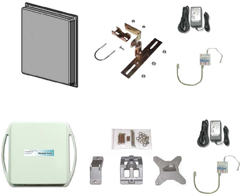
1.2 Marquee Kit Contents
Each Marquee kit includes the following (refer to Figures 1.1a and b):
• Outdoor radio with mounting hardware (two each)
• Surge protected Cat 5 DC Power Injector (two each)
• 110/240 VAC to 48 VDC power supply (two each)
• CD-ROM with Windows-based Configurator software
• User’s Manual
A Terabeam outdoor Ethernet cable must be ordered separately per unit. Available lengths are 50, 100,
200, or 300 feet.
Figure 1.1a – Components of Marquee FP Enclosure
(Two Each for a Marquee Bridge P-P Configuration)
Figure 1.1b – Components of Marquee EX Enclosure
(Two Each for a Marquee Bridge P-P Configuration
Version 1.2 Page 2 February 2005

Marquee™ Point-to-Point Series User Guide
Section 2
Installation
Safety Warning
This equipment complies with FCC radiation exposure limits set forth for
an uncontrolled environment when installed as directed. The equipment
should be installed and operated outdoors with fix-mounted antennas
such that there will be a minimum of 2 meters of separation distance
between the antenna and all persons during normal operation. This
includes integrated, attached and external antenna versions of
equipment. If you are using dish antennas, the minimum separation
distance must be 2.56 meters.
CAUTION
2.1 Introduction
The Marquee is intended for professional installation only. Please review the entire manual before
powering up or deploying these units.
NOTE: It is strongly recommended that you configure and test the units prior to deploying them in the
field. Set up a “mini-network” that resembles your actual configuration as close as possible.
By using such a mock-up, troubleshooting potential problems will be much easier than if you
already installed the equipment in the field. Read through this entire Section 2 to understand
how to install the hardware. To configure the Marquee, read Section 3.
2.2 DC Power Injector
The Cat 5 DC Power Injector is not in a waterproof enclosure and must be protected from the weather. It
can be permanently mounted to a surface using the double stick tape found on the back of it.
2.3 Power Supply
The Marquee kit comes with a 110/220 VAC to 48 VDC power supply that has a standard barrel plug
[center pin positive (+) tip and outer ring negative (-)].
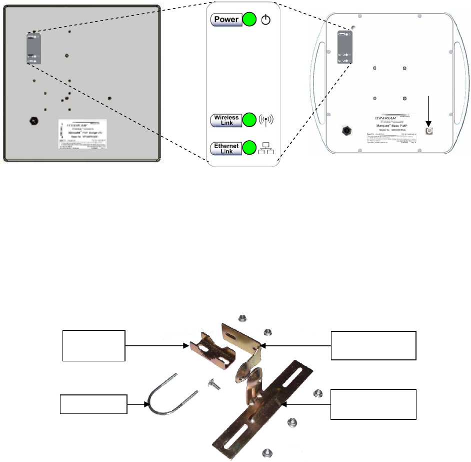
2.4 LEDs
Three LEDs are present on the back of the Marquee (see Figures 2.1a and b):
• The green Power LED stays on when the unit is plugged and operating correctly
• The green Wireless Link LED flashes when there is traffic over the wireless medium
• The green Ethernet Link LED flashes when there is traffic over the Ethernet port
Version 1.2 Page 3 February 2005
Marquee™ Point-to-Point Series User Guide
Figure 2.1 – Marquee LEDs
(a) Flat Panel (FP) Version (b) Ruggedized (EX) Version
: d with all-weather electrical tape, Permagum, or
he Marque mounting bracket (A) that is secured to the pole with a
Figure 2.2 – Marquee FP Mounting Hardware
N-Type
Connector
for External
Antenna
2.5 Hardware Installation – FP Enclosure
NOTE All connectors must be properly water-proofe
equivalent. Do not use Silicon glue.
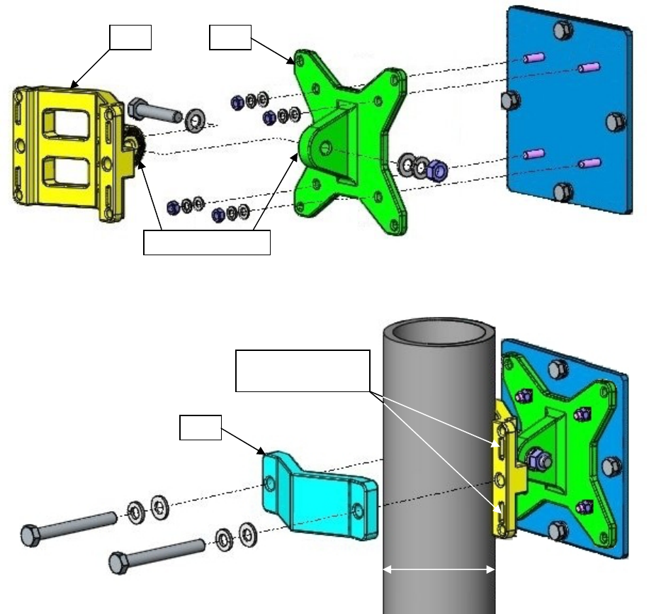
e FP unit is installed by using a pole T
pivot adaptor bracket (B), a pole clamp (C), and a U-bolt (D). Figure 2.2 shows the hardware provided to
mount the Marquee FP unit.
Pole
Clamp (C)
U-Bolt (D)
Pivot Adaptor
Bracket
(
B
)
Pole Mounting
Bracket (A)
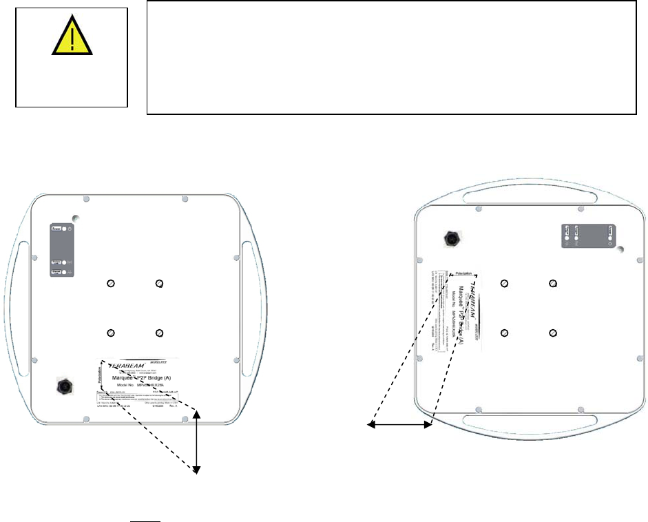
he integrated antenna can be mounted either vertically or horizontally polarized. The label located on T
the back of the unit contains an arrow indicating the antenna’s polarization (see Figures 2.3a and b).
Please note that both ends of the link must use the same polarization. Be aware that most omni
antennas are vertically polarized and if the Marquee FP is aimed at one, it must be installed vertically
polarized, i.e., with the polarization arrow up and down.
Version 1.2 Page 4 February 2005
Marquee™ Point-to-Point Series User Guide
Figure 2.3 – Marquee FP Orientation
(a) For Vertical Polarization (b) For Horizontal Polarization
Circula
r
Tab
(A)(A)
Polarization
Arrow
Polarization
Arrow
1. Fit the pole mounting bracket (A) to the two studs protruding from the back of the Marquee FP unit
according to the desired polarization, as shown in Figures 2.3a and b. Position the bracket so that the
side that has the circular tab is pointing towards the center of the unit. Secure to the unit by threading
two nuts and tighten them firmly with an appropriate wrench.
2. Attach the pivot adaptor bracket (B) to the pole mounting bracket (A) by using bolt and nut, as shown
in Fig 2.4. Tighten hardware (one place). IMPORTANT: Ensure that convex edge of the pivot adaptor
bracket (B) is facing concave edge of the pole mounting bracket (A).
Figure 2.4 –Assembly of Pivot Adaptor Bracket (B) to Pole Mounting Bracket (A)
(B)
(A)
Version 1.2 Page 5 February 2005
Marquee™ Point-to-Point Series User Guide
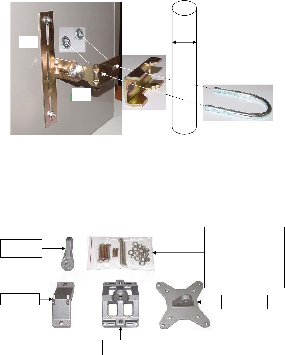
3. Turn the pivot adaptor bracket (B) so that the rectangular part is parallel with the surface of the
Marquee FP. Fasten the Marquee unit to the pole using pole clamp (C), U-bolt (D), and two nuts, as
shown in Fig 2.5. Tighten hardware (two places). The pole clamp (C) and U-bolt (D) will accept pole
diameters between 0.75” to 1.5” OD.
Figure 2.5 – Attaching the Marquee FP Unit to the Pole
(D)
(B)
(C)
Min 0.75”
Max 1.5”
(A)
Proceed to Section 2.7 – Cabling the Marquee (All Enclosures).
2.6 Hardware Installation – EX Enclosure
NOTE: All connectors must be properly water-proofed with all-weather electrical tape, Permagum, or
equivalent. Do not use Silicon glue.
The Marquee EX unit is installed by using an “X”-shaped adaptor bracket (A) that is secured to the pole
with a pole mounting bracket (B), and a pole clamp (C). Figure 2.6 shows the hardware provided to mount
the Marquee EX unit.
Figure 2.6 – Marquee EX Mounting Hardware
Hardware Qty
Screw Hex Head M5x20 4
(for Gigalink 5x45 only)
Screw Hex Head M8x40 4
(for poles between 1” to 1.75” OD)
Screw Hex Head M8x70 2
(for poles between 1.75” to 3” OD)
Lock Washer M5 4
Flat Washer M5 4
Nut M5 4
Lock Washer M8 4
Flat Washer M8 6
Nut M8 2
Arm (For indoor
installations only,
not used)
“X”-Shaped Adaptor
Bracket (A)
Pole Clamp (C)
Pole Mounting
Bracket (B)
Version 1.2 Page 6 February 2005
Marquee™ Point-to-Point Series User Guide
The antenna can be mounted either vertically or horizontally polarized. If you are using a Marquee with a
23 dBi FP attached antenna, the label located on the back of the unit shows an arrow indicating the
antenna’s polarization (see Figures 2.7a and b). Please note that both ends of the link must use the
same polarization. Be aware that most omni antennas are vertically polarized and if the Marquee EX is
aimed at one, it must be installed vertically polarized, i.e., with the polarization arrow up and down. If you
are using a Marquee with an external antenna, there is no arrow on the label located on the back of the
unit and an additional N-type female jack is present to connect a short coax cable to the antenna (see
Figure 2.1b). All previous considerations regarding polarization are applicable to the external antenna.
Figure 2.7 – Marquee EX With Attached Antenna Orientation
(a) For Vertical Polarization (b) For Horizontal Polarization
Polarization
Arrow Polarization
Arrow
WARNING
If you are using a Marquee with an external antenna, the unit must be
operated with a proper antenna, microwave load or terminator plugged
into the N-type female jack on the back of the unit. Operating the
Marquee with nothing connected to the jack may result in damage to the
TX section of the unit which will not be covered by the factory warranty
and will be a billable repair.
1. Fit the adaptor bracket (A) to the four studs protruding from the back of the Marquee EX unit, by
aligning the four inner holes with the mounting studs on the back of the unit and securing to the u
using four nuts, lock washers, and flat washers, as shown in Figure 2.8. Tighten hardware (four
places). IMPORTANT: Note the position of the serrated edge of bracket (A).
Attach the pole mounting bracket (B) to adaptor bracket (A) by using one M8x
nit
. 40 bolt and flat washer
. s,
ng
2on one side, and nut, lock washer and flat washer on the other, as shown in Fig 2.8. Tighten hardware
(one place). IMPORTANT: Ensure that the serrated edges on both brackets are facing each other.
Fasten the unit to the pole using pole clamp (C) and two M8x70 bolts, lock washers, and flat washer3as shown in Fig 2.9. Tighten hardware (two places). The pole mounting bracket (B) will accept pole
diameters between 1.75” to 3” OD. You may attach the Marquee unit to smaller diameter poles,
between 1” to 1.75” OD, by flipping over the pole clamp (C) so the convex part faces the pole and
using two M8x40 bolts. The Marquee unit can also be mounted to larger pole diameters by discardi
pole clamp (C) and replacing it with metal straps (not included) fastened through slots located on the
pole mounting bracket (B).
Version 1.2 Page 7 February 2005
Marquee™ Point-to-Point Series User Guide
Figure 2.8 – Detail Showing Assembly of Pole Mounting Bracket to Marquee EX
Figure 2.9 – Attaching the Marquee EX Unit to the Pole
Slots for optional
metal straps
Proceed to Section 2.7 – Cabling the Marquee (All Enclosures).
2.7 Cabling the Marquee (All Enclosures)
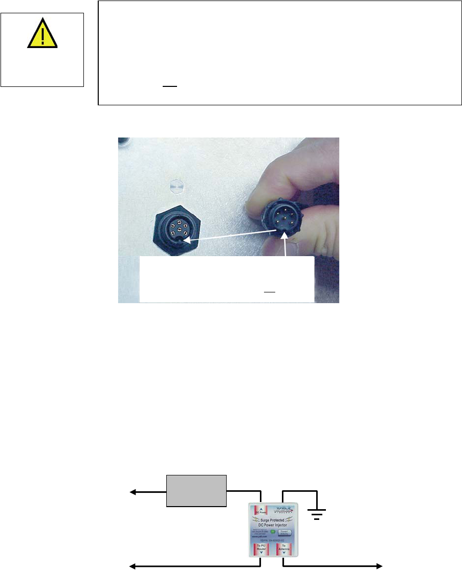
1. Ensuring that there is no DC power applied to the cable, plug the 6-pin N-male round connector of the
outdoor Ethernet cable (ordered separately) into the rear jack of the unit, making sure the notch on
the connector is correctly aligned with the tab on the jack as shown on Figure 2.10. Turn the round
locking nut clockwise as you push in until it securely fastens onto the jack. Please verify that the
round connector is properly plugged into the rear jack of the antenna prior to connecting DC
power because it is possible to push it in the wrong way if enough force is used. If DC power is
applied and the connector is not properly plugged, damage to the electronics of the unit or the
connector itself may occur which will not be covered by the factory warranty.
Serrated Ed
g
es
Max 3.0”
Min 1.0”
B
A
C
Version 1.2 Page 8 February 2005
Marquee™ Point-to-Point Series User Guide
Figure 2.10 – Plugging the Outdoor Ethernet Cable
2. Attach the other end of the outdoor Ethernet cable to ctor at port RJ-45
labeled “To Antenna.”
3. Connect the Ethernet cabl PC/Router” r Injector into a regular
port on your router, switch or hub. If you connect to a computer or PC, use a cross-over cable or
adapter.
4. Perform an Earth ground connection to any of the rear bolts of the unit, the mounting brackets, or the
mast (if metallic). For maximum protection, also connect the metal wire of the surge protected DC
Injector to ground as shown on Figure 2.11.
Figure 2.11 – Installation of the Terabeam Surge d DC Injector
for Maximum Grounding Protection
5.
the Cat 5 DC Power Inje
e labeled “To from the Cat 5 DC Powe
Protecte
If you are using a Marquee unit with an external antenna, connect the antenna to the N-type female
jack on the back of the unit.
RJ-45 Ethernet Connector
To Switch, Router or PC To Marquee
Surge Protected
DC Injector
AC Power
Power Supply
Ground Wire
Plug the connector into the jack by
aligning the notch with the tab
Caution not: Be sure DC Power is
when
p
lu
gg
in
g
the c applied
able
If DC Power is applied while you are attempting to insert the round
effort to find the key, DC power pins will momentarily touch the Ethernet
pins. Ethernet circuitry on the board will be
dama lso, do not apply excessive pressure when you insert the
round connector or the pins will pop out. Any damage caused by this
action will not
connector into the jack, it is possible that, as you rotate the plug in an
If this happens the
ged. A
be covered by the factory warranty and will be a billable
repair.
WARNING
Version 1.2 Page 9 February 2005
Marquee™ Point-to-Point Series User Guide
Version 1.2 Page 10 February 2005
6. Connect the barrel plug Injector,
then plug the Power Su turns
on. If there is traffic ove the
Ethernet p t is active t
7. I gurator
are goi e the an
antennas.
):
• A 23 dBi flat panel integrated to the FP enclosure
• A 23 dBi flat panel attached to the EX enclosure
• An external antenna
• The purpose of the following steps is to adjust the Line-of-Sight of the antennas in order to
maximize the main lobe SNR (Signal-to-Noise Ratio) level. Regardless of the type of antenna
that you are using, the procedure involves making an azimuth (horizontal) alignment and an
elevation (vertical) alignment. The steps below pertain to integrated and attached antennas, but
they are also applicable to llow the specific alignment
instructions of the corresp figuration, you are going to align
both antennas on each en
PORTANT: During this process, all Ma at the same stage of the installation
cat
lly
ote used to describe either of the three types.
ts
Note: If y eans that
yo alignment of
both antennas by usi ing” at each other. Place the
cursor anywhere in the List of Scanned Devices box and right-click the mouse. A Re-scan
local net n will appear. Click on the button. If the pa e still does not
appear, repeat these steps until it is displayed.
of the power supply to the “DC Power” jack on the Cat 5 DC Power
pply into an AC outlet. Check that the red Power LED on the Marquee
r the wireless medium the green Wireless Link LED should be flashing. If
he green Ethernet Link LED should be flashing.
program on a laptop or PC and configure your system (see Section 3). You
tenna alignment and link monitoring screen of the program to align the
or
nstall the Confi
ng to us
2.8 Antenna Alignment
There are three possible antennas that you can use with the Marquee unit (refer to Table 1.1
external antennas as long as you fo
onding manufacturer. For a P-P con
d.
rquee units must be IM
pro edure and powered ON. It is assumed that you have configured your units (see Section 3) and th
there is communication between the Configurator program and your Marquee units. Unless specifica
d, the term “antenna” isn
1. Perform a coarse alignment of the antenna by using a compass heading so it is roughly “looking” at i
remote partner.
2. Connect the near end Marquee unit to the laptop or PC where the Configurator program is installed by
using a crossover Ethernet cable. Run the Configurator. Verify that the unit where you are locally
connected to as well as its remote partner are both displayed on the Main Screen (Fig. 2.12).
ou cannot see the partner Marquee unit on the Main Screen, that probably m
ur antenna is so misaligned that it cannot link to its partner. Perform a coarse
ng a compass heading so they are “look
work butto rtner Marque
Marquee™ Point-to-Point Series User Guide
Figure 2.12 – Configurator Main Screen
Local Marquee
Remote Marquee
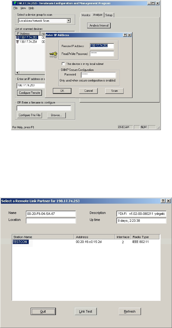
in onto the local unit (Fig. 2.13). Click the Analyze tab, then click the Wireless Link Test button.
Enter IP Address window appe
3. Log
The ars (Fig. 2.14). The IP address and the password should be
e correct sinc you just logged in. Click OK.
Figure 2.13 – Login Screen
Version 1.2 Page 11 February 2005
Marquee™ Point-to-Point Series User Guide
Figure 2.14 – Enter IP Address Screen
5. appears (Figure 2.15). Verify that you have the partner
Marquee unit displayed in the box, click on it and then click the Link Test button (or double-click the
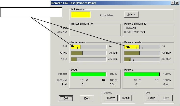
partner unit). The Remote Test Li 16). The main goal now is to peak
the SNR levels at both ends of the link.
Figure 2.15 – Select a Remote Link Partner Screen
4. Click the Wireless Link Test button. Again, the Enter IP Address window appears. Click OK.
The Select a Remote Link Partner window
nk window is shown (Figure 2.
Version 1.2 Page 12 February 2005
Marquee™ Point-to-Point Series User Guide
Figure 2.16 – Remote Test Link Screen
Maximize these levels
adings
for both ends of the link peak. Start with azimuth adjustment on the far end of the link first (if
7. Using the Elevation adjustment bolt (see Figure 2.17a or b), adjust the elevation until the SNR
readings for both end far end of the link first (if
applicable). It is recomme ould adjust through
the maximum SNR reading until the reading clearly drops and continues to drop to lower level side-
lobes. Adjust back until the maximum is again attained. Then repeat for the near end of the link.
8. Repeat steps 7 and 8 above to guarantee optimum alignment for maximum signal strength.
9. CAUTION: It is possible to obtain a false peak SNR reading from the signal of a side-lobe. Up to
three different side-lobes on either side of the main lobe may give false peak alignment readings. For
this reason, it is important that a wide sweep in both azimuth and elevation is made in order to identify
these false peak SNR readings so to zero in on the true peak alignment reading due to the main
antenna beam.
10. Tighten the two Azimuth adjustment bolts while observing the SNR reading to ensure the azimuth
alignment does not change while tightening.
11. Tighten the Elevation adjustment bolt while observing the SNR reading to ensure the elevation
alignment does not change while tightening.
12. Test the Link. Prior to placing the link in service for network traffic, the link should be tested using
standard network procedures.
6. Using the Azimuth adjustment bolts (see Figure 2.17a or b), adjust the azimuth until the SNR re
applicable). It is recommended that, in order to ensure the true maximum, you should adjust through
the maximum SNR reading until the reading clearly drops and continues to drop to lower level side-
lobes. Adjust back until the maximum is attained again. Then repeat for the near end of the link.
s of the link peak. Start with elevation adjustment on the
nded that, in order to ensure the true maximum, you sh
Version 1.2 Page 13 February 2005
Marquee™ Point-to-Point Series User Guide
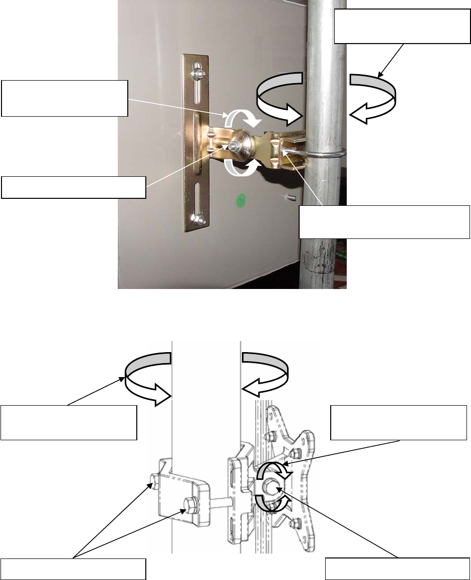
Figure 2.17a – Final Lin zation (FP Enclosure)
e-of-Sight Adjustment for Signal Optimi
(threaded on U-bolt behind plate)
Figure 2.17b – Final Line-of-Sight Adjustment for Signal Optimization (EX Enclosure)
Rotate in this plane for
azimuth alignment Rotate in this plane for
elevation alignment
Elevation adjustment bolt
Azimuth adjustment bolts
Rotate in this plane for
azimuth alignment
Elevation adjustment bolt
Azimuth adjustment bolts
Rotate in this plane for
elevation alignment
Version 1.2 Page 14 February 2005
Marquee™ Point-to-Point Series User Guide
Section 3
Configuration
3.1 Installing the Management Software
The Windows-based Configurator software can be installed on a laptop or PC running Windows 98, ME,
2000, NT, or XP. This software has a GUI (Graphical User Interface), which makes it easy to use. The
program allows you to locally or remotely perform the following procedures:
its running on the network
e current configuration of the units
• Load and save configurations
• Update the firmware of the units
Note: Prior to installing a newer version of the Configurator program, you will need to remove any
older versions:
1. Under the Start button on your desktop, go to Settings.
2. Click on Control Panel.
3. Choose Add/Remove Programs.
4. Select Configurator.
5. The software will uninstall itself.
Windows Installation – To install the Configurator in Windows, perform the following steps:
1. Insert the CD-ROM included in the Marquee kit into the appropriate drive of your computer. Using
you y:
\Management Software\Configurator. Run the Configurator Installation program (the .exe file).
2. The InstallShield runs. Follow the onscreen instructions to install the Configurator. If you are installing
the u are
upgrading from a previous installation, your files will be stored in the directory where you last saved
the Configurator files. The InstallShiel urato sktop.
3. The InstallShield Wiza cate successful installation of the
Configurato to complete the installation.
3.2
After igurator installation, you gure your M
following steps provide a quick pro started. For m th information about the
Configurator and its commands, menus, and option se refe figuration
Guide, available as a pdf file on your CD ROM. Also, an onlin p is available by pressing F1 or clicking
Hel
IMPORTANT: Your Ma st be on the same sub here the Configurator
ve a routable IP address, in ord ou
will get a status of Offline for the units (see the Status
LEDs show activity. In order to be able to configure the units, change the IP address of
your computer to a 198.17.74.x sub-net (the Marquee’s default sub-net configured from
factory). Once you have access to the units, you can assign a new IP address to them
Setup tab and IP Host button.
• Display a list of un
• Display and edit th
r Windows Explorer open the contents of the CD-ROM drive and select the following director
program for the first time, files are stored in the directory \Program Files\Configurator. If yo
d also installs shortcuts to the Config r on your de
rd Completed screen will appear to indi
r. Click Finish
Using the Configurator
completing the Conf arquee system. The are ready to confi
cedure to get you ore in-dep
r to the Marquee Series Cons plea e hel
p-> Index from the main screen.
rquee units mu net as the computer w
er to access them. If not, y
column in Figure 3.1) even if the
program is installed, or ha
later by clicking on the
Version 1.2 Page 15 February 2005
Marquee™ Point-to-Point Series User Guide
3.3 Configuring the Marquee
The Marquee is shipped from factory pre-c and with the proper transmit power
settings. The units are set with the following default IP addresses:
198.17.74.251 and 198.17.74.252
ome of the parameters that you may need to change are the following:
nnec
2. Double- open the directory where the
Configu s\Configurator) and run the
program
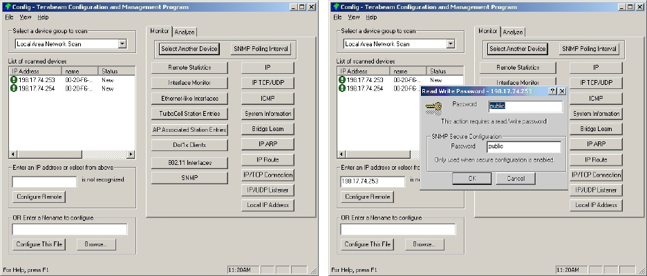
3. The Ma To scan for devices on the network, place the cursor
anywhe evices box and right-click the mouse. A Re-scan local network
button w f devices will appear.
. Click on the device you wish to configure. The selected device IP address will appear in the text box
e Marquee
unit). Click this button.
5.
afe
place.
onfigured for operation
Marquee Bridge P-P (2 each):
The default read/write password is public.
S
• IP addresses
• Read/Write password
• Radio frequency channel
1. Co t a crossover Ethernet cable from the Cat 5 DC Power Injector to your laptop or PC.
click the Configurator shortcut on your desktop. You may also
rator program has been installed (the default is \Program File
config.exe.
in Screen shown in Figure 3.1 appears.
re in the List of Scanned D
ill appear. Click on the button. A list o
4above the Configure Remote button (alternatively, you can enter here the IP address of th
A Read/Write Password text box will appear (see Figure 3.2). The default password is public. Click
the OK button. It is suggested that you change the password later, write it down and keep it in a s
Figure 3.1 – Configurator Main Screen Figure 3.2 – Login Screen
Version 1.2 Page 16 February 2005
Marquee™ Point-to-Point Series User Guide
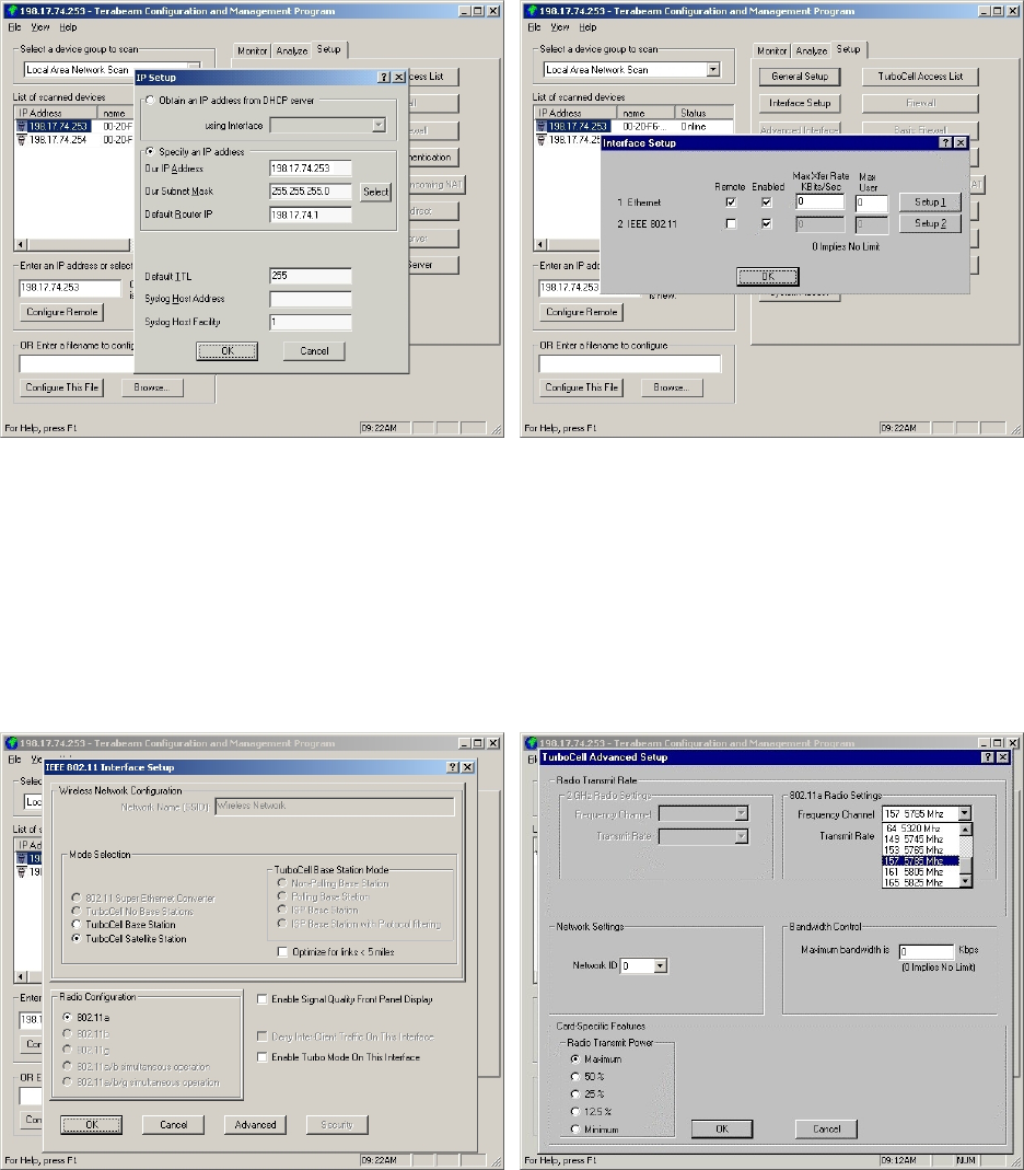
6. After you login successfully, the Setup screen appears. Click on the IP Host button. The IP Setup ss.
. Back to the S e Setu appears
(see Figure
Figure 3.4 – Interface Setup Screen
screen appears (see Figure 3.3). Enter the IP Address, Subnet Mask, and Default Router IP Addre
Click OK.
7 etup screen, click on the Interfac p button. The corresponding screen
3.4).
Figure 3.3 – IP Setup Screen
8 Click on Setup 2. The IEEE 802.11 Setup
. screen appears (see Figure 3.5). Select the type of Station
this Marquee is going to be. In a P-P configuration one unit must be Base and the other must be
9. Click the Advanced button. The corresponding screen appears (see Figure 3.6). Select a Frequency
C units in a link mus
frequency value.
Figure 3.5 – IEEE 802.11 Interface Setup Screen Figure 3.6 – TurboCell Advanced Setup Screen
Remote (Satellite). Radio Configuration must be set to 802.11a. Leave the rest of the buttons
unchanged.
hannel from the pull down menu box. Both t be configured with the same
Version 1.2 Page 17 February 2005
Marquee™ Point-to-Point Series User Guide
10. The Marquee is optimized for a transmit rate of 24 Mbps and the transmit power is preset from facto
with the proper value.
ry
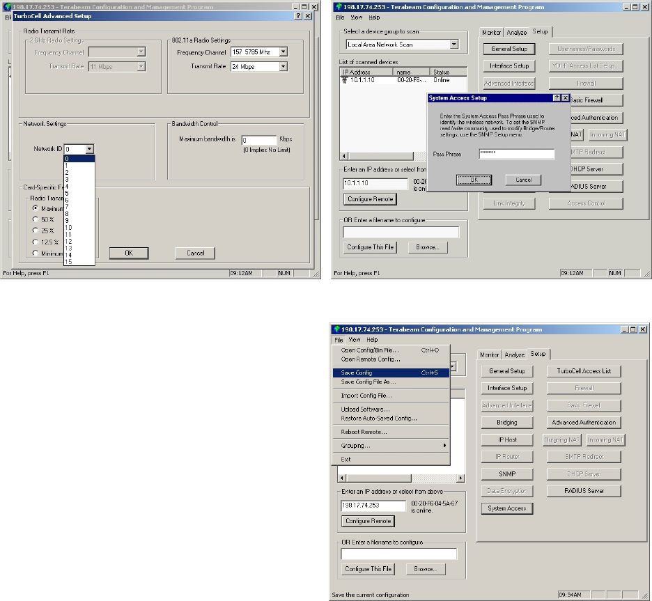
1. Click the Network ID button. The corresponding screen appears (see Figure 3.7). Select a number
2. Click
13. Click the System Access button. The corresponding screen appears (see Figure 3.8). Enter a Pass
Phrase to identify the wireless network. Both units in a link must be configured with the same Pass
Phrase value. Click OK.
Figure 3.7 – TurboCell Advanced Setup Screen Figure 3.8 – System Access Setup
Network ID
1from 0 through 15 to identify your network. Both units in a link must be configured with the same
Network ID value.
1OK. Click OK again.
Figure 3.9 – Save Configuration
15. After the Marquee has finished saving its
configuration, exit the Configurator program.
The Marquee is ready to use. Refer to the
Marquee Series Configuration Guide,
available as a pdf file on your CD ROM, or the
online help for complete instructions on setting
up other features in the unit.
14. Go to File and click Save Config: this will save
the new settings (see Fig. 3.9).
Version 1.2 Page 18 February 2005

Marquee™ Point-to-Point Series User Guide
Appendix A – Marquee Technical Specifications
Table A.1 – Network Features
twork device type Ethernet bridge, IP router
cess Control
Ne
Media Ac oint networks
en node
et traffic
TurboCell Polling Protocol
• Yes
• Yes
• Yes
• Engineered for multip
• Eliminates 802.11 hidd
• Adaptive Dynamic polling algorithm
• SuperPacket Aggregation
• Optimized for Intern
• Yes
• Yes
RADIUS Authentication Yes
IP Routing RIP II
Bridging Yes, 100% transparent (protocol independent)
Bridge Filters MAC address, Protocol ID
Spanning Tree Yes
Automatic channel searching CPEs Yes
Encryption DES (56-bit)
Blowfish (128 bit)
AES (128 Bit) [Upgradeable Q4 ‘04]
Note: Encryption option lowers throughput since it is
done in software.
Watchdog Reboot Timer Yes
DHCP Client & Server Yes
Static and Dynamic IP address Yes
NAT Yes
Roaming in the subnet Yes
Bandwidth Management:
• Configurable for each remote location
• Configurable for each interface
Yes
• Yes
• Yes
SNMP Management
MP Support
Yes, GUI Management utility included
SN MIB II and Private MIB
Extensive Online Help Yes
Table A.2 –Marqu
equency 5.
turn Loss
ee FP Enclosure Specifications
Fr 725 – 5.850 GHz
Re 12 dB, minimum
Gain 23 dBi
E-plane Beamwidth 7 degrees
H-plane Beamwidth 8.5 degrees
Peak Sidelobe Level -10 dB
Version 1.2 Page 19 February 2005

Marquee™ Point-to-Point Series User Guide
Table A.3 – Physical & Environmental Features
r) RJ-45, 10/100 Base-T
Ethernet Interface (at POE injecto
Ethernet Cable Length 300 ft maximum
RF Interface (external antenna
m els N-F
od ) emale
ng Temperature Range to 60°C (-22°F t
e Temperature -40° to 75°C (-40°F t
pe ng Humidity rati 100% (non-imm
Altitude 1000 ft (300 meters)
Power Scheme Pow Ethernet (POE) Cat 5 DC Injector er over
Power Supply 110/220 VAC, 50-60 Hz
Power Consumption 16 W Max
Current Draw 0.5 A Max
Input Voltage Required at Radio +36 to +57 VDC, nominal +48 VDC (supplied via POE)
Dimensions (H x W x D) FP E 3 x 15.3 x 1.13 in (389 x 389 x 29 mm)
EX E x 3.25 in (305 x 356 x 83 mm)
nclosure: 15.
nclosure: 12 x 14
nclosure: 2.90 lbs (1.32 Kg)
nclosure: 9.65 lbs (4.38 Kg)
or, all-weather
LED status indicators Pow ireless Link, and Ethernet Link er, W
Min – Max Diameter of Mounting Pole
Table A.4 – rnal A
Terabeam Part No. Description
A5.3FP23-M Flat Panel, 1 ft, 5.875 GHz 23 dBi gain, 5.150 to
A5.8FP28-M anel, 2 fFlat P t, 28 dBi gain, 5.150 to 5.875 GHz
A5.8-2’-G Dish, 2 ft, 28.5 dBi gain, 5.250 to 5.850 GHz
A5.8-2.5’-G Dish, 2.5 ft, 31 i gain, 5.250 to 5.850 GHz .2 dB
A5.8-4’-G
Operati -30°C o 140°F)
Storag C o 167°F)
O0% to ersion rain)
Weight FP E
EX E
Enclosure Outdo
For FP Enclosure: 0.75 – 1.5 in
For EX Enclosure: 1.0 – 1.75 in or 1.75 – 3.0 in
Recommended Exte ntennas for the Marquee Series
Dish, 4 ft, 34.8 dBi gain, 5.250 to 5.850 GHz
Version 1.2 Page 20 February 2005

Marquee™ Point-to-Point Series User Guide
n 1.2 Page 21 February 2005
Table A.5 –
5.8 GHz Freque
RF
ncy
Feat
Spe
ure
cs
s
4.9 GHz Frequency Specs
40 – 4990 MHz
ngle
ndwcha
idthnne
of l: 4
20 965
MH M
z with a
le up to 54 Mbps ser selec le u bps
24 Mbps fo ingl operation
QP
Yes
ard ve
ed v
-86 dBm @ 6 Mbps
-30 dBm
nditions of th
Operational Frequency Band 5725 – 5850 MHz 49
Channels (user se erlapping Si Hz
ba
lectable) 5 non-ov
ata Rate User sele
ughput
1
24 Mbps
2
OFDM-Q
Divi
ut Power +1
+2
4 d
3 d
nsitivity
3
-7
-8
4 dB
3 dB
ve Level -30 dB
Over-The-Air D U tab p to 54 Mctab
PSK
sion
for s
for a
@ 3
@ 6
Versio
Thro r s e channel
Modulation Scheme OFDM- SK
Radio Operation Time Duplex (TDD) Time Division Duplex (TDD)
FCC Certified Yes
Transmit Outp Bm tand rsion
Bm mplifi ersion
+10 dBm for standard version
+23 dBm for amplified version
Receiver Se m 6 Mbps
m Mbps
-77 dBm @ 24 Mbps
-84 dBm @ 12 Mbps
Maximum Recei m
1
This is a typical figure. Actual throughput varies according to the specifications of the antenna used and the co e terrain.
2
The throughput of a MCL58HFP23I is 18 Mbps.
3
Actual receiver sensitivity for individual products may vary based on manufacturing process and environmental variations.