YDI Wireless MB-HP Outdoor Transmitter User Manual Manual Marquee P P
YDI Wireless Outdoor Transmitter Manual Marquee P P
UserManual.wiki
>
YDI Wireless
>
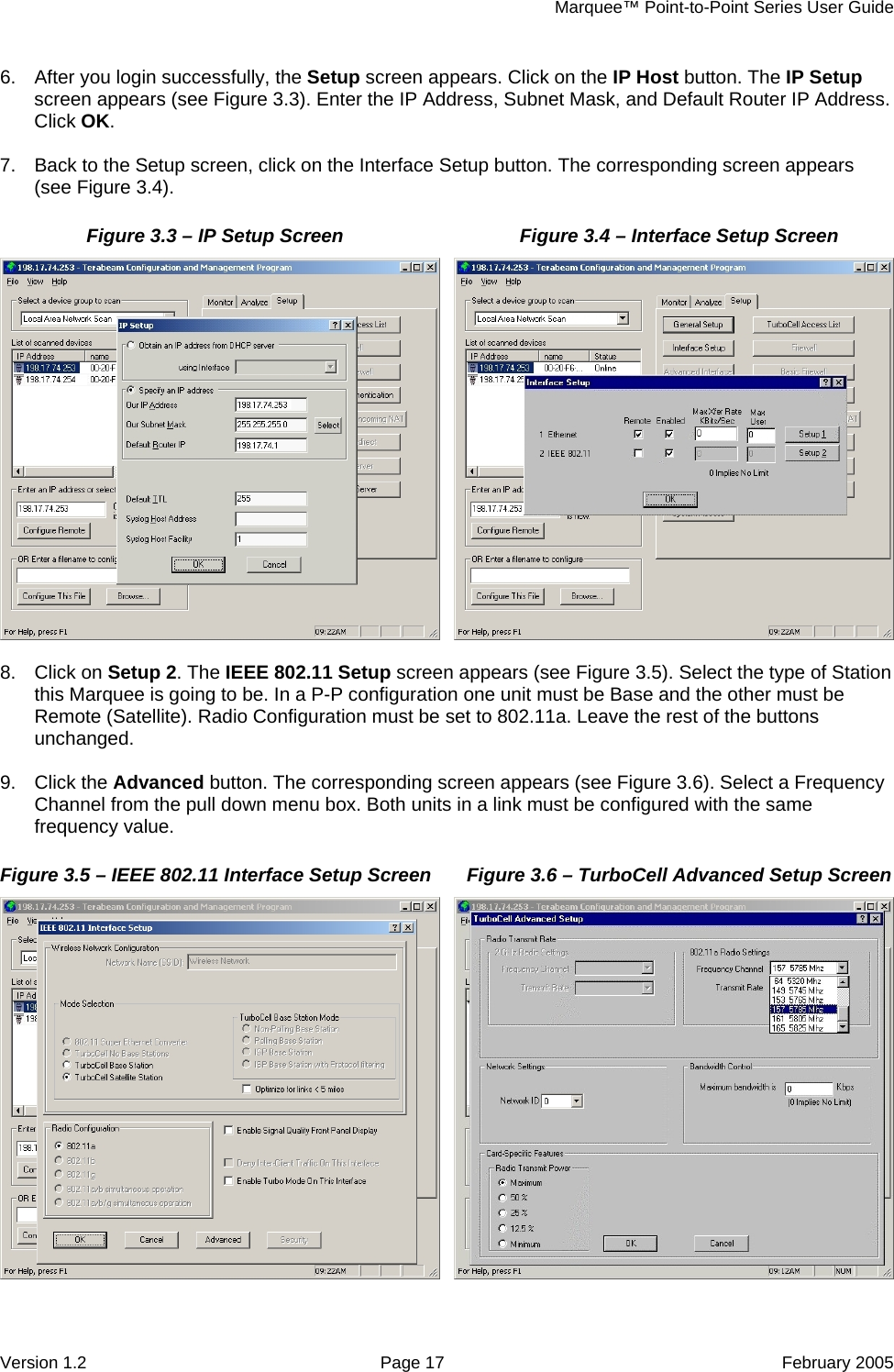
MB-HP User Manual
>
Manual Marquee P P
Contents
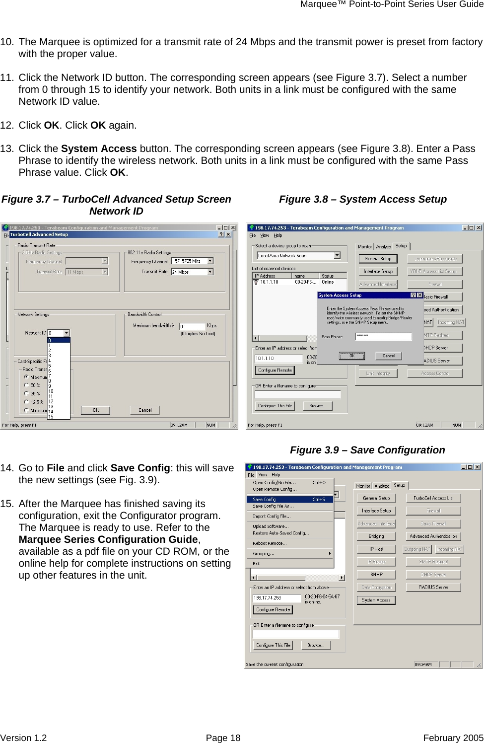
1.
Manual
2.
Manual Marquee P MP
3.
Manual Marquee P P
Manual Marquee P P
Navigation menu
Upload a User Manual
Namespaces
Wiki Guide
HTML
PDF
Info
Views
User Manual
Discussion / Help
Navigation
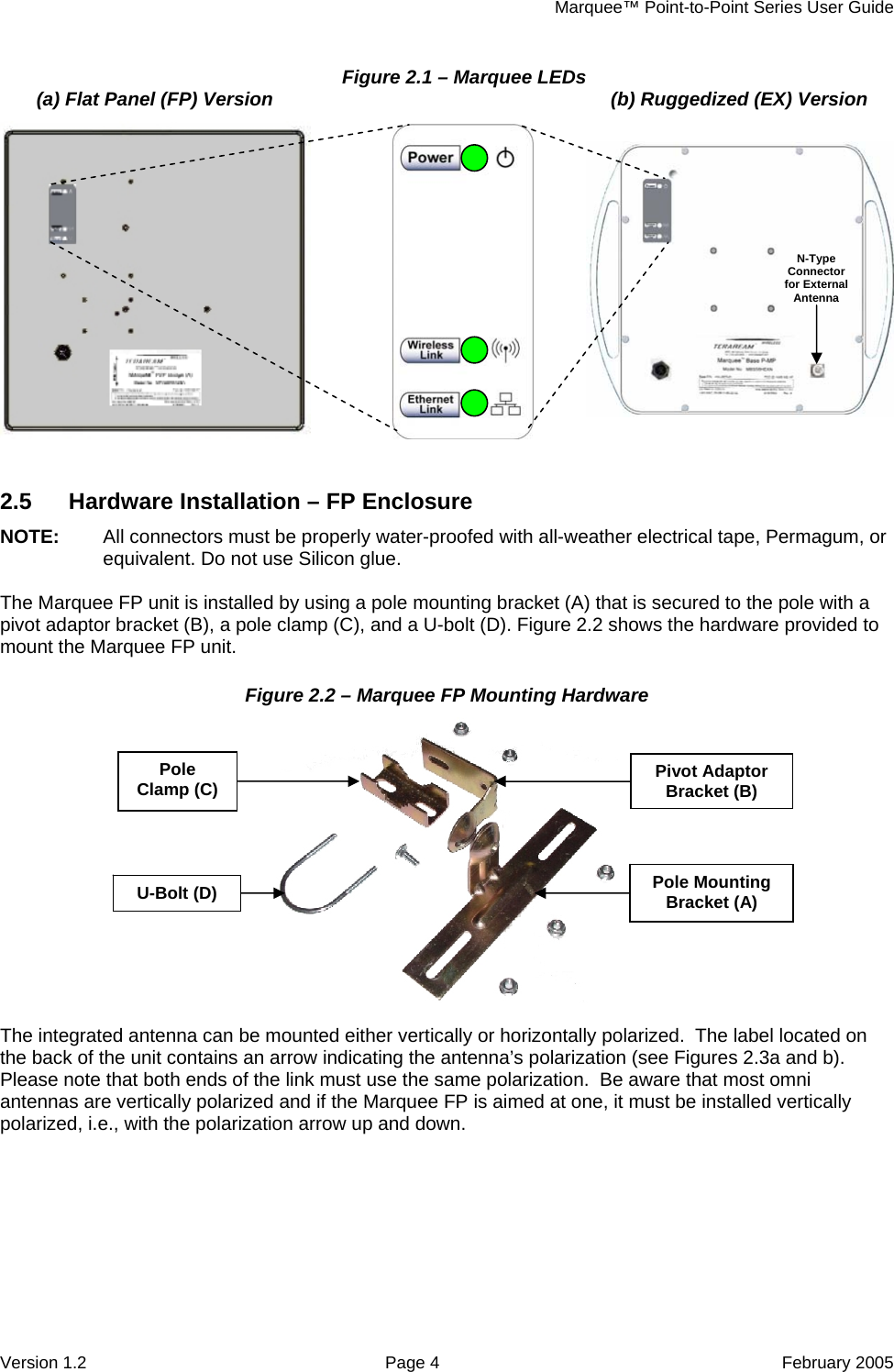
![Marquee™ Point-to-Point Series User Guide Section 2 Installation Safety Warning This equipment complies with FCC radiation exposure limits set forth for an uncontrolled environment when installed as directed. The equipment should be installed and operated outdoors with fix-mounted antennas such that there will be a minimum of 2 meters of separation distance between the antenna and all persons during normal operation. This includes integrated, attached and external antenna versions of equipment. If you are using dish antennas, the minimum separation distance must be 2.56 meters. CAUTION 2.1 Introduction The Marquee is intended for professional installation only. Please review the entire manual before powering up or deploying these units. NOTE: It is strongly recommended that you configure and test the units prior to deploying them in the field. Set up a “mini-network” that resembles your actual configuration as close as possible. By using such a mock-up, troubleshooting potential problems will be much easier than if you already installed the equipment in the field. Read through this entire Section 2 to understand how to install the hardware. To configure the Marquee, read Section 3. 2.2 DC Power Injector The Cat 5 DC Power Injector is not in a waterproof enclosure and must be protected from the weather. It can be permanently mounted to a surface using the double stick tape found on the back of it. 2.3 Power Supply The Marquee kit comes with a 110/220 VAC to 48 VDC power supply that has a standard barrel plug [center pin positive (+) tip and outer ring negative (-)]. 2.4 LEDs Three LEDs are present on the back of the Marquee (see Figures 2.1a and b): • The green Power LED stays on when the unit is plugged and operating correctly • The green Wireless Link LED flashes when there is traffic over the wireless medium • The green Ethernet Link LED flashes when there is traffic over the Ethernet port Version 1.2 Page 3 February 2005](https://usermanual.wiki/YDI-Wireless/MB-HP.Manual-Marquee-P-P/User-Guide-594105-Page-6.png)
![Marquee™ Point-to-Point Series User Guide Appendix A – Marquee Technical Specifications Table A.1 – Network Features twork device type Ethernet bridge, IP router cess Control NeMedia Ac oint networks en node et traffic TurboCell Polling Protocol • Yes • Yes • Yes • Engineered for multip• Eliminates 802.11 hidd• Adaptive Dynamic polling algorithm • SuperPacket Aggregation • Optimized for Intern• Yes • Yes RADIUS Authentication Yes IP Routing RIP II Bridging Yes, 100% transparent (protocol independent) Bridge Filters MAC address, Protocol ID Spanning Tree Yes Automatic channel searching CPEs Yes Encryption DES (56-bit) Blowfish (128 bit) AES (128 Bit) [Upgradeable Q4 ‘04] Note: Encryption option lowers throughput since it is done in software. Watchdog Reboot Timer Yes DHCP Client & Server Yes Static and Dynamic IP address Yes NAT Yes Roaming in the subnet Yes Bandwidth Management: • Configurable for each remote location • Configurable for each interface Yes • Yes • Yes SNMP Management MP Support Yes, GUI Management utility included SN MIB II and Private MIB Extensive Online Help Yes Table A.2 –Marquequency 5.turn Loss ee FP Enclosure Specifications Fr 725 – 5.850 GHz Re 12 dB, minimum Gain 23 dBi E-plane Beamwidth 7 degrees H-plane Beamwidth 8.5 degrees Peak Sidelobe Level -10 dB Version 1.2 Page 19 February 2005](https://usermanual.wiki/YDI-Wireless/MB-HP.Manual-Marquee-P-P/User-Guide-594105-Page-22.png)