YDI Wireless MR-1 2.4GHz INDOOR SIGNAL BOOSTER User Manual Introduction
YDI Wireless 2.4GHz INDOOR SIGNAL BOOSTER Introduction
Contents
- 1. MANUAL
- 2. RT 11788 Quick Start Guide
MANUAL
Max Ranger
Quick Start Guide
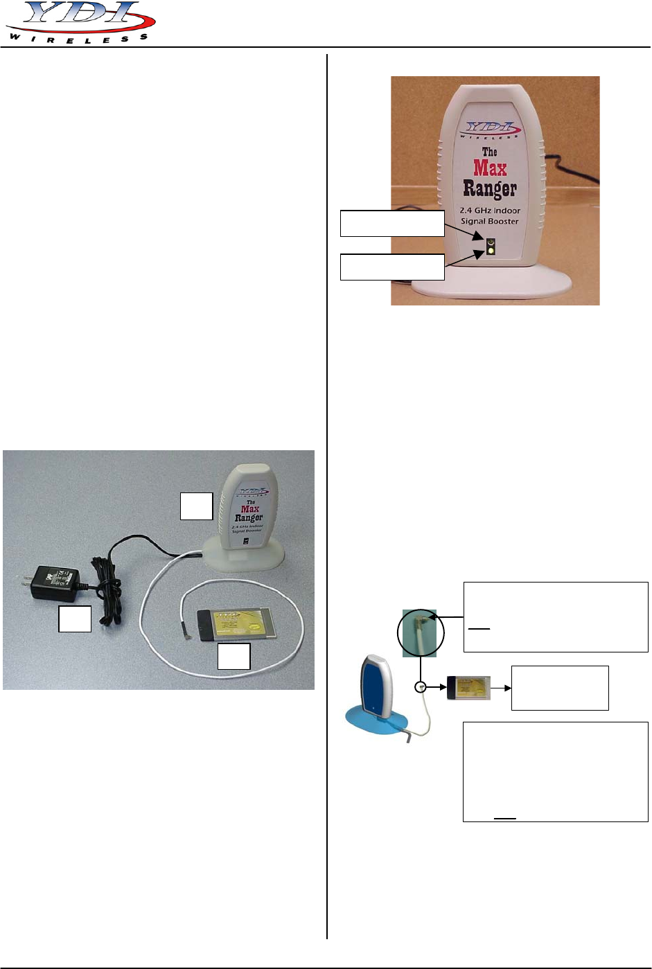
Figure 2 – Max Ranger LEDs
Introduction
The Max Ranger is an antenna with an integrated bi-
directional amplifier used to extend the indoor range of
802.11b Wireless LAN cards. The Max Ranger is
designed to be used with YDI/Agere PCMCIA WLAN
cards that can be inserted into any suitable device such
as an Access Point, YDI Ethernet Converter (EC), or
even a laptop computer. It is easy to install and ready
to work “right out of the box”. The internal antenna is
horizontally polarized for optimum RF connection to
other WLAN cards which typically are also horizontally
polarized. It features over 300 mW (+25 dBm) of
transmit power (EIRP). It is FCC Part 15 Certified for
license-free operation with our Sidekick and Sapphire
WLAN cards, and is capable to work in a temperature
range of 0°C to +50°C.
Max Ranger Kit Contents Installation
1. Antenna with integrated bi-directional amplifier and
RF cable terminated in antenna connector for the
YDI/Agere WLAN card
The Max Ranger radio unit can be placed near the
computer or device on a tabletop.
2. YDI Sidekick Wireless LAN card
1. Remove the small black plastic cap from the
proprietary antenna jack of the WLAN card with
your finger nail or a small screwdriver.
3. 110/220 VAC to 5 VDC wall mount power supply
Figure 1 – Max Ranger Kit
2. Plug the RF cable that is attached at the bottom of
the Max Ranger to the proprietary antenna jack on
the WLAN card as shown on figure 3.
CAUTION: The antenna connector is a tight push-on fit.
Figure 3 – Connecting the Max Ranger
to the WLAN Card
Warning:
Insert the WLAN card into the appropriate
slot making sure that:
1) The WLAN Card is upside (brand label must
be visible)
2) It slides smoothly across the internal rails of
the slot
3) It is gently pushed all the way in
Proprietary Antenna Connector.
It must be inserted straight into the WLAN card.
Warning: Insert this end into the WLAN card
gently.
Do not twist when removing it or you may
damage the connector!
Insert into a compatible
Access Point,
YDI EC, or
Laptop computer
LEDs
Two LEDs are present on the front of the Max Ranger
(see Figure 2):
• The Red LED flashes when the Max Ranger
transmits data
• The Green LED indicates that the Max Ranger is in
receive mode
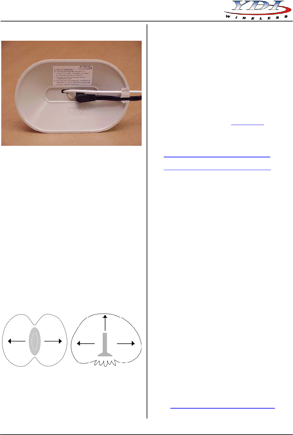
3. Plug the DC power connector into the jack at the
bottom of the Max Ranger as shown on Figure 4.
Push the cable into the notch in the base to insure
the Max Ranger is stable on the tabletop.
4. Plug the power supply into a standard wall outlet.
Red LED (Tx)
Green LED (Rx)
2
1
3
MNL-500120-001 – Rev 1.1 1 August 2003
Max Ranger
Quick Start Guide
August 2003 2 MNL-500120-001 – Rev 1.1
Figure 4 – Plugging the DC Power Connector into
the Bottom Jack of the Max Ranger
Technical Support
Your primary source of assistance is the dealer from
which you purchased this product. The YDI support staff
should only be contacted directly if you purchased this
product directly from YDI.
NOTE: Before you contact Technical Support, please
make sure that you have read and thoroughly
understood all instructions outlined on this
manual.
YDI Wireless Tel.: 703-205-0600
8000 Lee Highway Fax: 703-205-0610
Falls Church, VA 22042 E-mail: tech@ydi.com
USA www.ydi.com
The latest software and User’s Manuals can also be
found at:
http://www.ydi.com/support/downloads.php
Operation
http://www.ydi.com/support/documents.php
1. To find the best position for your Max Ranger, YDI
recommends to use the Signal Strength Indicator
found on the Link Test screen of the Wireless Client
Manager for your WLAN card. You can also use the
YDI Client Manager for EC. For a detailed
explanation on how to use each software, please
refer to the User’s Manual of your specific product.
FCC NOTICE
This antenna/transmitter device complies with FCC
radiation exposure limits set forth for an uncontrolled
environment when installed as directed. The antenna
used for this transmitter must be installed and operated
with a minimum separation distance of at least 20
centimeters (8 inches) from all persons during normal
operation, and must not be co-located or operating in
conjunction with any other antenna or transmitter.
Users and installers must adhere to the antenna
installation instructions and transmitter operating
conditions in order to comply with the FCC’s RF
exposure requirements.
2. Aim the Max Ranger by turning it back and forth
until the maximum signal strength is reached.
Antenna Patterns
The Max Ranger boosts the signal the most in the front
and back directions (Figure 5a) as well as out of the top
(Figure 5b). The weakest signal will be at the bottom
and sides.
This device complies with part 15 of the FCC rules.
Operation is subject to the following two conditions:
Figure 5a Figure 5b
Top View Showing the Side View Showing the
Strongest Signal Maximum Coverage Area
Facing the Flat Parts Out of the Top and Sides
(1) This device may not cause harmful interference, and
(2) This device must accept any interference received,
including interference that may cause undesired
operation.
NOTE: The manufacturer is not responsible for any
radio or TV interference caused by
unauthorized modifications to this equipment.
Such modifications could void the user's
authority to operate the equipment.
The Max Ranger is certified by the FCC for use with the
PC24E-11-FC/R series of YDI Wireless LAN cards
made by Agere.
To see all our FCC certified systems, please visit:
http://www.ydi.com/deployinfo/fcc-info.php