YDI Wireless USB-ANT-E WLAN Card w/USB User Manual Emerald USB Antenna
YDI Wireless WLAN Card w/USB Emerald USB Antenna
UserManual.wiki
>
YDI Wireless
>
USB ANT E User Manual
Users Manual
Navigation menu
Upload a User Manual
Namespaces
Wiki Guide
HTML
PDF
Info
Views
User Manual
Discussion / Help
Navigation
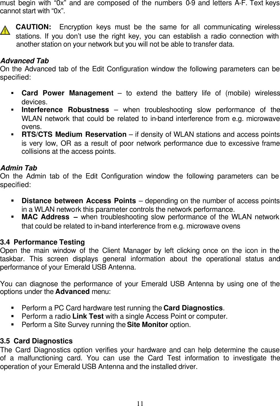
![22Appendix B: DEFINITION OF TERMS 2.4 GHz band – radio operating band designated license-free by the FCC 802.11b – IEEE standard for high-speed wireless data network communications Access Point (AP) – a wireless device that regulates and directs communications among several wireless clients Adapter – an internal or external circuit board that attaches to a computer to allow support for various devices; a network adapter (like the USB Client Station Adapter) enables a computer to connect to a network Ad Hoc – peer-to-peer computer network; wireless clients communicate directly to each other; usually for temporary networks Channel – a specific frequency band used in wireless communication Client Station – any computer on a network that requests information or services from another computer (a server) and acts according to the server’s response Data Frame – bits of data to be transmitted over the network DHCP Server – [Dynamic Host Configuration Protocol Server] – automatically assigns IP addresses to client stations ESSID – Extended Service Set Identifier – name of the network FCC – Federal Communications Commission Fragmentation Threshold – any data frame larger than this threshold will be divided into smaller pieces before transmission GHz – Gigahertz IEEE – Institute of Electrical and Electronics Engineers – a professional organization that sets standards for data communications Infrastructure – server-based computer network; wireless clients communicate through an Access Point; used for long range or large networks or internetworks IP Address – [Internet Protocol Address] – a unique number used to identify computers on a network; can be static (manually assigned) or dynamic (periodically assigned by DHCP server)](https://usermanual.wiki/YDI-Wireless/USB-ANT-E/User-Guide-173502-Page-25.png)
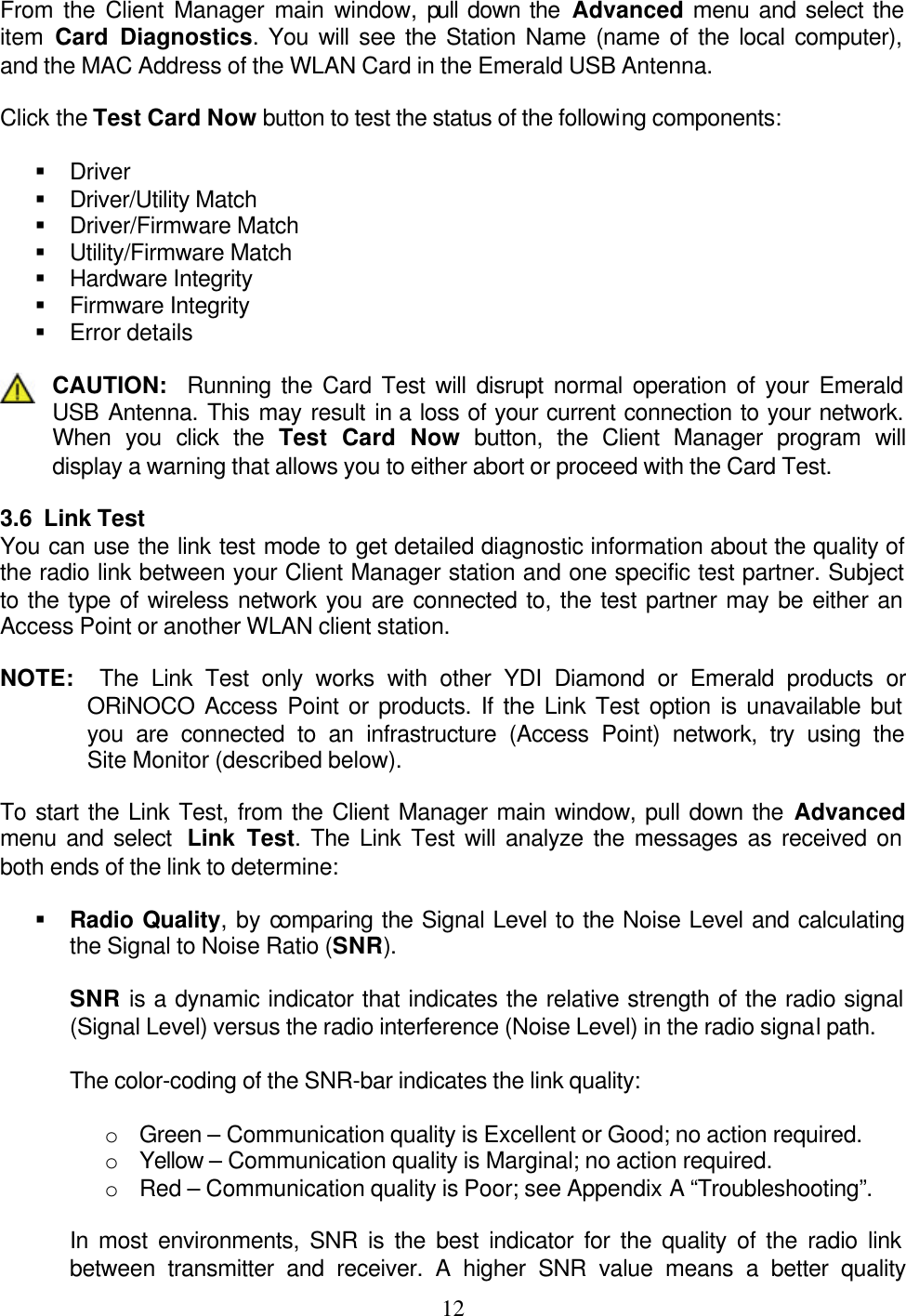
![23MAC Address – [Media Access Control Address] – a permanent, unique identifier assigned to all network adapter cards (at the time of manufacture) Mbps – Megabits per second PC Card – a credit card-sized device consistent with PCMCIA standards, used mainly in notebook computers; the Type II PCMCIA Card (PC Card) used with the USB Client Station Adapter can attach to any computer with a USB interface PCMCIA – Personal Computer Memory Card International Association – sets standards for devices used with portable computers RTS/CTS – Request To Send/Clear To Send – signals used by computers on a network to determine when to transmit data RTS Threshold – any data frame larger than this threshold requires the sender to use the RTS/CTS signal Subnet Mask – determines which part of an IP address should be used to identify the network and which part to identify a station on that network TCP/IP – Transmission Control Protocol/Internet Protocol – a method of communicating to computers on different networks USB – Universal Serial Bus – an interface standard for peripheral devices on a computer, such as a mouse, keyboard, network adapter, etc](https://usermanual.wiki/YDI-Wireless/USB-ANT-E/User-Guide-173502-Page-26.png)