YDT Technology A800 RFID Reader User Manual rev
YDT Technology International Co. Ltd RFID Reader rev
User Manual rev.pdf
RFID Reader A800 User Manual
(Preliminary)
Version 1.2
October 14, 2014
1

FCC Notice:
This equipment has been tested and found to comply with the limits for a Class A digital device, pursuant to
Part 15 of the FCC Rules. These limits are designed to provide reasonable protection against harmful
interference when the equipment is operated in a commercial environment. This equipment generates, uses, and
can radiate radio frequency energy, and if it is not installed and used in accordance with the instruction manual,
it may cause harmful interference to radio communications. Operation of this equipment in a residential area is
likely to cause harmful interference in which case the user will be required to correct the interference at his own
expense.
FCC Caution:
Any changes or modifications not expressly approved by the party responsible for compliance could void the
user's authority to operate this equipment.
This device complies with part 15 of the FCC Rules. Operation is subject to the following two conditions:
(1) This device may not cause harmful interference, and
(2) This device must accept any interference received, including interference that may cause undesired
operation.
2

Radiation Exposure Statement:
This equipment complies with FCC radiation exposure limits set forth for an uncontrolled environment. This
equipment should be installed and operated with minimum distance 22cm between the radiator and your body
Caution:
The YDT A800 reader has been tested to meet all regulatory requirements offered in the jurisdiction.
Following rules should be complied strictly.
1. User ought to avoid opening the reader housing for any reason.
2. Below are several particular actions that violate regulatory requirements and should be forbidden without
permission:
A. Change operation frequency compliant with regulatory requirements.
B. Increase RF operating output power.
C. Change external antennas type.
D. Modify the design or functions of the reader.
The usage of RFID reader must NOT cause interference on flight safety and other legal communication
systems. If any, the RFID reader should be shut down until proper improvement is achieved.
Professional installation instruction:
1. Installation personal
This product is designed for specific application and needs to be installed by a qualified personal who
has RF and related rule knowledge. The general user shall not attempt to install or change the setting.
2. Installation location
The product shall be installed at a location where the radiating antenna can be kept 22 cm from nearby
person in normal operation condition to meet regulatory RF exposure requirement.
3. External antenna
Use only the antennas which have been approved by the applicant. The non-approved antenna(s) may
produce unwanted spurious or excessive RF transmitting power which may lead to the violation of
FCC limit and is prohibited.
4. Installation procedure
Please refer to user’s manual for the detail.
5. Warning
Please carefully select the installation position and make sure that the final output power does not
exceed the limit set force in relevant rules. The violation of the rule could lead to serious federal
penalty.
3
Table of Contents
RFID Reader A800 User Manual (Preliminary) ........................................................... 1
FCC Notice:........................................................................................................... 2
FCC Caution:......................................................................................................... 2
Radiation Exposure Statement:............................................................................. 3
Caution:................................................................................................................. 3
1. Product Overview...................................................................................................... 5
1.1 Hardware......................................................................................................... 5
1.2 Software .......................................................................................................... 9
2. Installation............................................................................................................... 10
2.1 Mechanical Dimensions................................................................................ 10
2.2 Electrical Installation..................................................................................... 14
2.3 Installation Notes........................................................................................... 15
2.4 Installation Cautions...................................................................................... 17
3. ReaderAP Software Tools ....................................................................................... 18
3.1 Reader Setup Tool (RST) .............................................................................. 18
3.1.1 Setup Wizard ...................................................................................... 20
3.1.2 Network Settings................................................................................ 24
3.1.3 Serial Settings..................................................................................... 26
3.2 Reader Test Tool (RTT)................................................................................. 27
3.2.1 Antenna Setting .................................................................................. 28
3.2.2 Tag Management ................................................................................ 31
3.2.3 Event Handling................................................................................... 35
3.2.4 Tag Performance................................................................................. 37
3.2.5 IO Control .......................................................................................... 38
3.3 Reader Diagnose Tool (RDT)........................................................................ 40
3.3.1 Tag Report .......................................................................................... 41
3.3.2 Power Ramp Tool............................................................................... 42
3.3.3 Tag Log............................................................................................... 43
4
1. Product Overview
RFID A800 is a multifunctional RFID reader professionally used in 902–928MHz UHF band,
which integrates all possible RFID functions for different environment. RFID A800 provides
flexible Input and Output ports without extra-used equipment, which can largely reduce the
system installation cost.
1.1 Hardware
The whole view of RFID A800 is as shown in Figure 1(a)(b), which marks all connected ports.
Detailed information is tabulated in Table 1. Figure 2 shows the LED indicator descriptions.
5
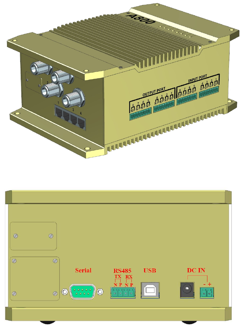
(a) Front view and Left side view
(b) Right side view
Figure 1 (a) Front view: 16 GPIO ports. Left side view: 4 RF ports and 4 RJ45 ports.
(b) Right side view: DC Jack, USB, RS232 and RS485 port.
6
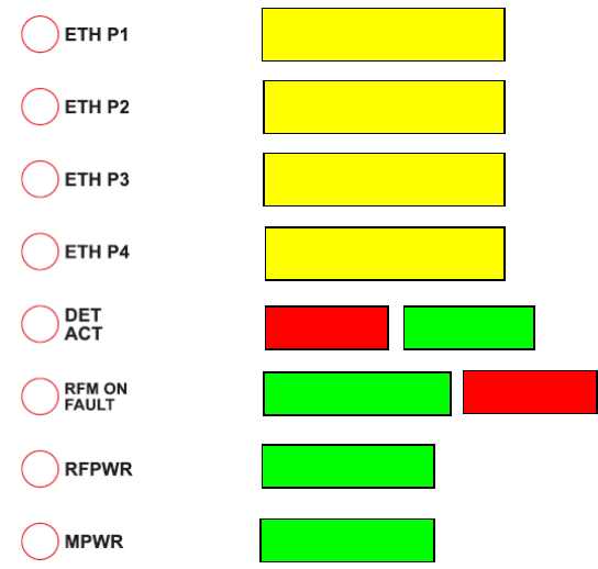
RJ45 Port 1 Yellow
RJ45 Port 2 Yellow
RJ45 Port 3 Yellow
RJ45 Port 4 Yellow
DET Red ACT Green
RFM ON Green FAULT Red
MPWR Green
RFPWR Green
Figure 2 LED descriptions.
7

Table 1 RFID reader function descriptions
Items Parameters Descriptions
1 Power Input 1 DC Jack and 1 Terminal Block two pins for Discrete two-wire
DC input for 12V or 24V DC, 2.5A maximum for 12V.
2 Electro-mechanical IO
Control Ports
Wet/Dry contact control Input 8 ports:
Two 4-port Terminal Block, one signal input and ground as a
pair of port.
Dry contact control Output 8 ports:
Two 4-port Terminal Block, differential pins as a pair of port.
3 Ethernet Ports 4 Ethernet ports for multi-user
4 RF reader Ports 4 ports of N type Female
5 USB B type, kept for engineering test of use
6 RS232 Ports 1 port , Kept for engineering test of use
7 RS485 1 full duplex 4-pin port, external controlling or engineering test.
8 Micro SD Card Holder Access door(port)
9 Future Use Port 1 Access door(port) optional for future use
10 Future Use Port 2 Access door (port) optional for future use
11 LED Indicators 8 LEDs:
4 x Ethernet ports Link, Yellow
1 x Main power, Green
1 x RF power, Green
1 x RFM ON, Green and Fault, Red
1 x RFID ACT, Green
RFID DET, Red
12 Operation Temperature 0°C ~ 60°C
13 Dimension 237.2 * 160.5 * 91.5 mm3
14 Weight 2.52kg
8

1.2 Software
YDT A800 series provides ReaderAP software tools for reader configuration and testing on
most of product features. The ReaderAP includes:
z Reader Setup Tool (RST)
Network settings, Protocol and Region settings…
z Reader Test Tool (RTT)
Antenna settings, Tag Management, IO Control…
z Reader Diagnose Tool (RDT)
Event report setting, Power Ramp tool, Tag Log…
Refer to chapter 3. ReaderAP Software Tools for detail.
9
2. Installation
2.1 Mechanical Dimensions
Figure 3, 4 and 5 show physical dimension with unit mm. User should put it into the suitable
case together with power adaptor to safely hold the operating equipment, wherever it is in
indoor or outdoor. The mounting screws are M4 size while mounting it to counterparts of
mechanical structure.
10
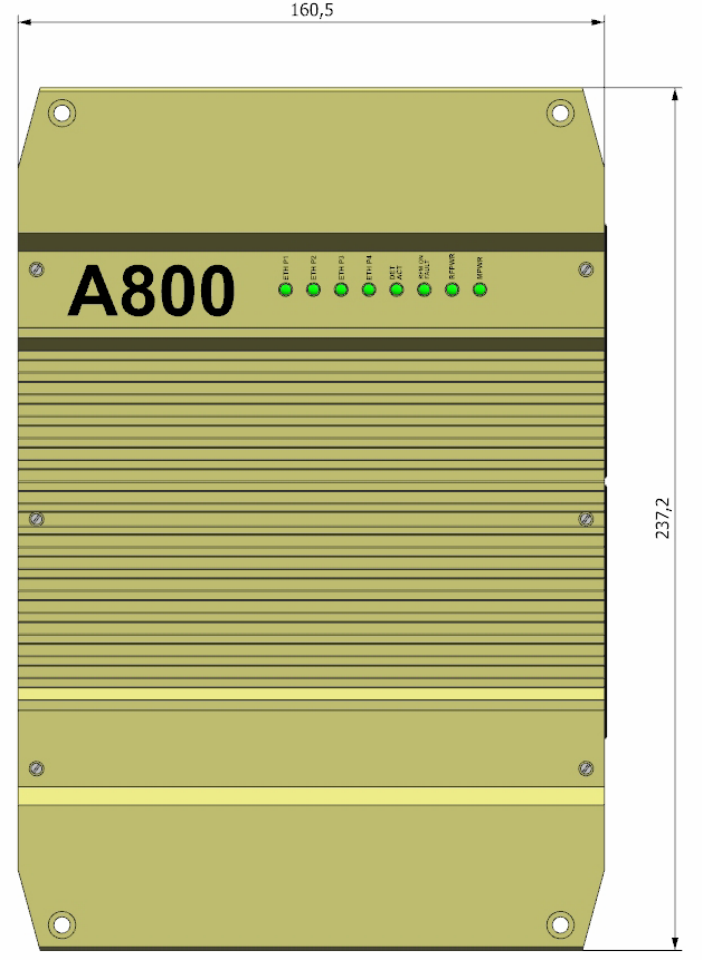
Figure 3 Dimensions in Top view.
11
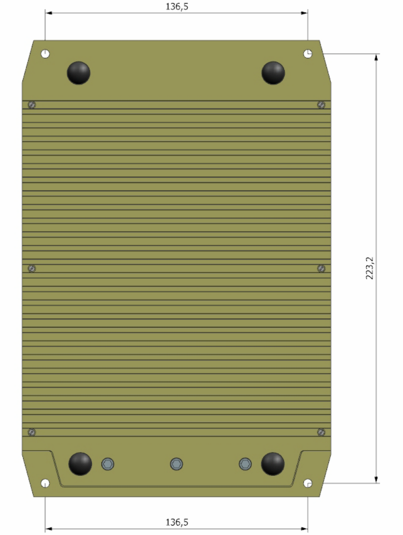
Figure 4 Dimensions in Bottom view. The 4 mounting holes are for M4 screws
and washers.
12
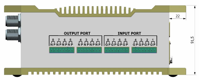
Figure 5 Dimensions in Front view.
13
2.2 Electrical Installation
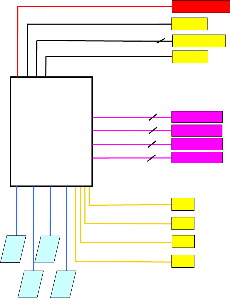
Figure 6 shows the connections between A800 and other
equipment.
Figure 6 Electrical connections on RFID reader.
RDC POWE 12V Power
RFID
A800
Reader
PC
PC
PC
PC
Port 4
Port 3 RJ45
Port 2
Port 1 RJ45
ANT1
ANT2
ANT3
ANT4
Loo
p
1-4
4 pairs of P and Ground input
Loo
p
5-8
4 pairs of P and Ground input
Barrier
4 pairs of P and N signal output
B
ar
ri
e
r
4 pairs of P and N signal output
Local PC
USB Type B
RS485
RS232
RS485 2 pairs of P and N signal
Local PC
14
2.3 Installation Notes
z DC Power
The adaptor input can be 100V or 240V AC max; standard output is 12V DC. One alternative
RS232
5200 Baud for RS-232 serial port for communication. The suggested maximum
USB
ult USB is type B connector, which is mainly used for local engineering test, not for
RS485
vide extra function for engineering test, which also can be selected as extended
Micro SD Memory Card
ed memory for easy hand-carry purpose. This function must
Electro-Mechanical Ports
to ground or voltage less than 3V, “1” is open to ground or
s P to N open.
, namely, the output is shorting of
input is Terminal block connector, but, it is not allowed to connect power with both DC Jack
and Terminal Block to different DC source.
z
Default 11
serial cable length is 3 meters.
z
The defa
general data transferred purpose.
z
RS485 pro
controlling purpose to be connected to a RS485 controller or equivalent equipment. This
function must depend on the software support. Contact manufacturer if needed.
z
This is mainly used as extend
depend on the software support. Contact manufacturer if needed.
z
1. 8 Input ports: “0” is short
voltage more than 5V, 30V maximum.
2. 8 Output ports: “0” is P to N short, “1” i
The output status of after power up will be default “0”
P and N. Unless user changes output status using software tools, it will keep the “short”
status. Therefore, user should take care of the initial process of applications-- if power is
not provided, the Output port is in “Open” status.
15

z Ethernet Ports
The Ethernet ports can provide high speed switch performance up to 1,000 Mbps.
By default, the IP address of RFID A800 is 192.168.1.8 and can be changed using Reader
Setup Tool (RST).
z Antenna Ports
Total 4 RF output ports can be connected. With default profile, all of the 4 ports will be
transmitted. Therefore, to select or deselect an antenna port, user should modify antenna
setting through Reader Setup Tool and Reader Test Tool in prior to RF power activated. For
insurance, it is recommended to make unconnected ports terminated with 50 ohms load.
Before removing an antenna or a load, user should deactivate the RF power.
User must be sure that cables are well connected before running “Perform Antenna Check”
operation in Reader Tests Tool (RTT) to avoid unexpected test results.
In practical application, while using the Antenna Port Detection function, some types of
antenna might NOT be detected well, and it will cause the” Perform Antenna Check”
function fail to detect the correspondent antenna. If so, follow the troubleshooting
information in section 3.2.1 Antenna Setting. The mismatch problem of Antenna Port
Detection on “Perform Antenna Check” does NOT mean the installed antenna is truly
malfunction, instead it is decided by the detection mechanism of the circuits. If users make
sure that everything related to the RF port is in normal condition, just skip the “Perform
Antenna Check” operation and use manual antenna selection instead. (Refer to 3.2.1
Antenna Setting)
z LED indicator
One of 4 Ethernet ports Linked, Yellow LED will light.
MPWR (Main power) and RFPWR (RF power) LED should be lighted green after
power on. If any of them doesn’t light, it means the reader is in malfunction.
FAULT LED will light in RED in two conditions:
1. During system initiation. (Turns OFF after system is ready.)
2. When system encounters some problem. (This function is pended and will be built in
line with future software support and fault definition. Contact the manufacture for further
information.)
RFM Power LED will light Green when alternative RF module function activated.
The function is pending at present version.
RFID ACT lights Green when RFID RF power is transmitted;
RFID DET lights Red while RFID detects possible tags.
16
2.4 Installation Cautions
The RFID reader is RF power transmitted product, for safety of equipment and operator, the
rules below should be followed,
A. Antennas should be located away from any person by more than 0.5 meters.
B. Reader should be grounded properly.
C. Any unconnected port, especially the center pin of RF port, should be rid of fingering
of person against ESD damage.
D. The antenna location should be kept away from other antenna of different transmitter,
particularly the near band of from 902 to 928MHz. Co-location interference could be
happened in worst condition.
17
3. ReaderAP Software Tools
The YDT A800 is delivered with ReaderAP tools for reader setup and configuration. To use
YDT ReaderAP, copy the ReaderAP folder from the CD-ROM into any path of the hard drive.
Make sure the three executable files (.exe) below are shown in the ReaderAP folder.
z PrjRST.exe --- Reader Setup Tool (RST) / Application Entry
z PrjRTT.exe --- Reader Test Tool (RTT)
z PrjRDT.exe --- Reader Diagnose Tool (RDT)
Check antennas and network setting according to Chapter 2 Installation. Make sure that YDT
A800 is in the same network segment as the PC running ReaderAP.
3.1 Reader Setup Tool (RST)
The Reader Setup Tool (RST) provides the entry to perform:
z View list of readers in the network segment.
z Launch Setup Wizard to set basic configuration.
z Launch Network Settings to modify a reader’s description and network settings.
z Launch Reader Test Tool (RTT) to do antenna, I/O, and tag management.
z Launch Reader Diagnose Tool (RDT) to perform power ramp test and dump system
logs.
Open YDT ReaderAP:
1. Run PrjRST.exe to open the main window.
2. For the first time you may receive security alert message from Windows firewall or
3rd party security applications. Unblock PrjRST.exe to continue executing
18
ReaderAP.
Warning: If there is advanced policy of security on the PC that causes YDT ReaderAP
unworkable, try to contact the network administrator for resolution.
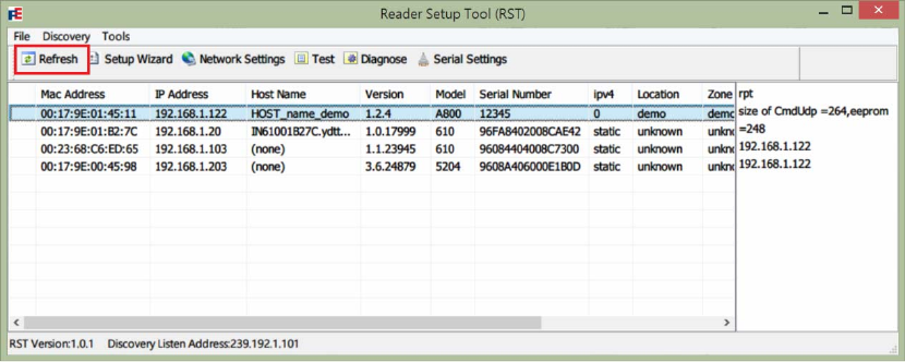
Select a specific reader:
1. Press Refresh button on the RST toolbar.
2. The list view will show available readers in the network segment.
3. Click on a reader list item to select a YDT A800 Model.
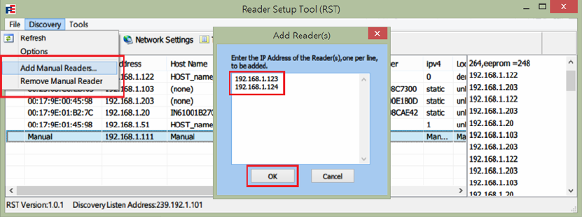
4. Or you can manually add readers by filling the IP list in
Discovery->Add Manual Reader, and remove a manual reader by clicking
Discovery->Remove Manual Reader.
19
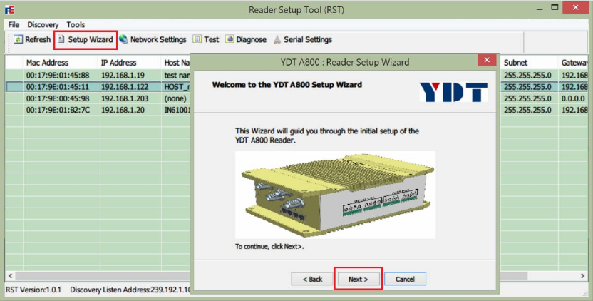
3.1.1 Setup Wizard
Initiate basic settings of a reader:
Note: The words of 610i in software title is temporary expression, it will be changed to
A800 for normal version.
1. Open the Reader Setup Tool (RST).
2. In the list view, select the reader to be configured. And then press Setup Wizard
button on the RST toolbar.
3. Press Next > button to start.
4. Select the protocol of the tags and press Next >. YDT A800 currently support only ISO
18000-6C EPC1-Gen2 protocol.
20
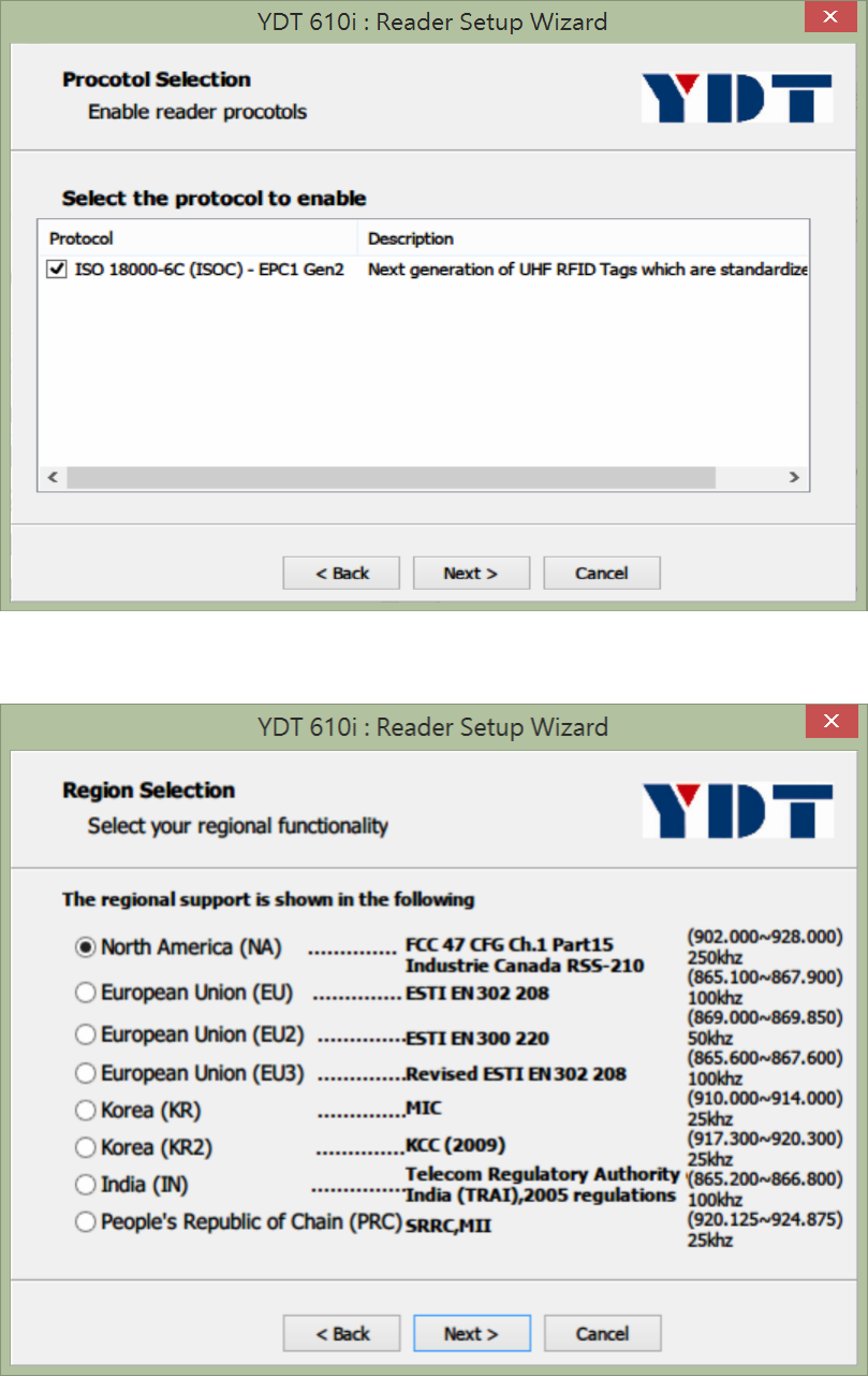
5. Select the region in which the reader is installed to configure the frequency
hopping range. Press Next > to continue.
6. Choose the used antenna ports with conducted power respectively. Press Next >
to continue.
21
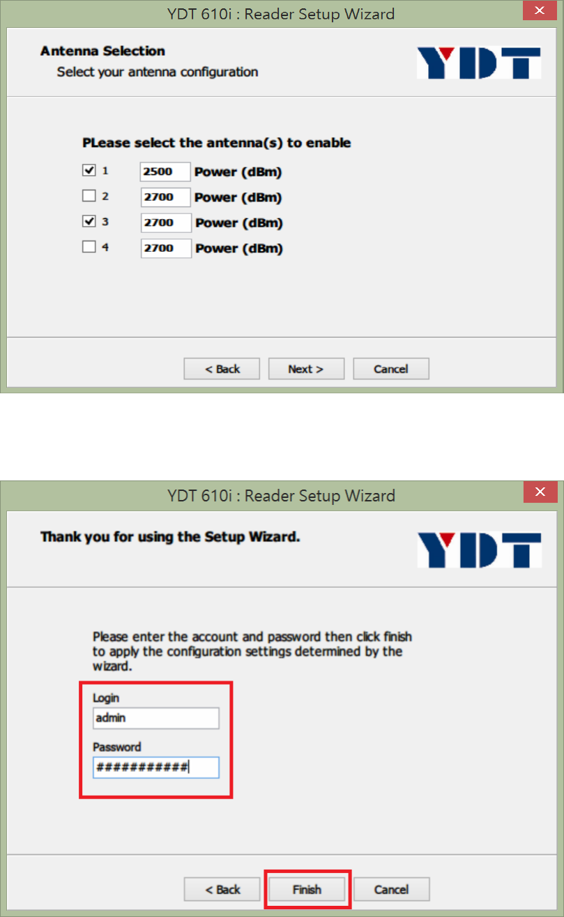
7. Enter login account / password (default: admin/readeradmin) of the reader with
administrator authority.
Warning: The maximum length of account/password is 16 bytes
8. Press Finish button to save settings.
22
9. Wait by 10 seconds for reloading profile. Press Refresh button on the toolbar of
Reader Setup Tool (RST) to renew reader list. If RST does NOT response for a
long time, reboot the reader manually (Power down Æ wait by 5 seconds Æ
power up Æ wait until FAULT Red LED turns off).
23
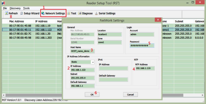
3.1.2 Network Settings
Change reader description and network settings:
1. In the list view, select the reader to be configured. Press Network Settings button on
the RST toolbar to open Network Settings dialog.
2. On the left side of Network Settings dialog, modify the network address information.
YDT A800 uses Static IP 192.168.1.8 by default.
3. In General area, edit Host Name, Location and Zone fields if it is necessary to
identify naming and location information of readers.
Warning: The maximum length of Host Name, Location and Zone is 16 bytes.
4. Edit NTP to assign IP address of time synchronization service.
5. In Login area, enter Account and Password of administrator authority. (default:
admin / readeradmin)
Warning: The maximum length of account and password is 16 bytes.
6. Press OK button to save settings.
7. After network settings changed, the reader will automatically reboot to reload the
configuration in profile. Please wait by 1 minute for reader startup. If RST does NOT
response for a long time, reboot the reader manually (Power down Æ wait by 5
seconds Æ power up Æ wait until FAULT Red LED turns off).
8. Press Refresh button to renew the list view in Reader Setup Tool.
24
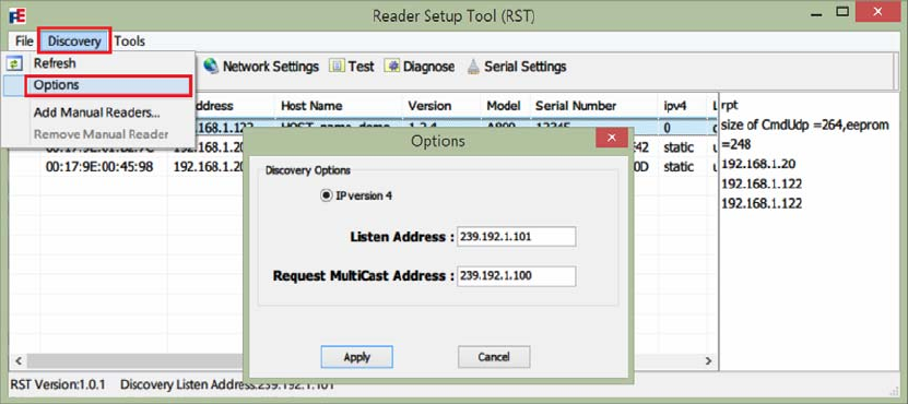
Customize Discovery Options:
1. In the Discovery menu in Reader Setup Tool (RST), select Options.
2. In the Options popup dialog, modify the broadcast settings.
Listen Address: IP address for listening UDP discovery packets.
Request Multicast Address: Broadcast IP address for sending out UDP update request
packets.
25
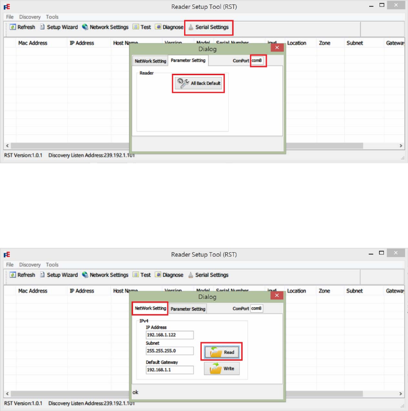
3.1.3 Serial Settings
Restore settings when network is unavailable:
1. Make sure the Serial Port (RS232) has been connected to PC.
2. Press Serial Setting button on the toolbar to open the serial settings dialog.
3. Enter ComPort which is an available serial port number of the PC. Default value is
“com8”.
4. Press All Back Default button in Parameter Setting tab to reset reader profile.
5. Wait by 10~20 seconds while overwriting reader profile.
6. Select Network Setting tab in the dialog. Press Read button to load settings from
reader.
7. Edit IP Address and other network settings if necessary.
8. Press Write button in the Network Setting tab to save settings to reader.
9. Reboot reader manually (Power down Æ wait by 5 seconds Æ power up Æ wait
until FAULT Red LED turns off) to reload the profile.
10. Run Setup Wizard or other configurations to setup the reader again.
26
3.2 Reader Test Tool (RTT)
The Reader Test Tool (RTT) is a utility for testing reader operations including:
z Antenna Setting
z Event Handling
z I/O Control
z Tag Management
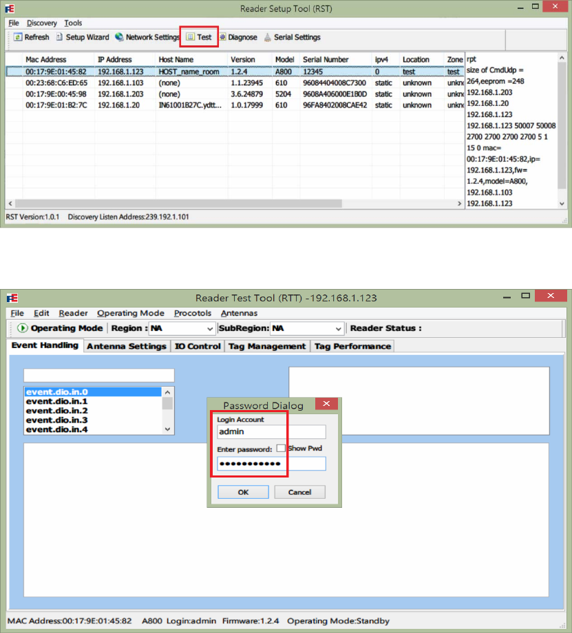
Open and Login into Reader Test Tool (RTT):
1. In the list view of Reader Setup Tool (RST), select a YDT A800 Model.
2. Press Test button to launch Reader Test Tool (RTT).
3. Login with Account and Password (default: admin/readeradmin) then press OK
button.
27
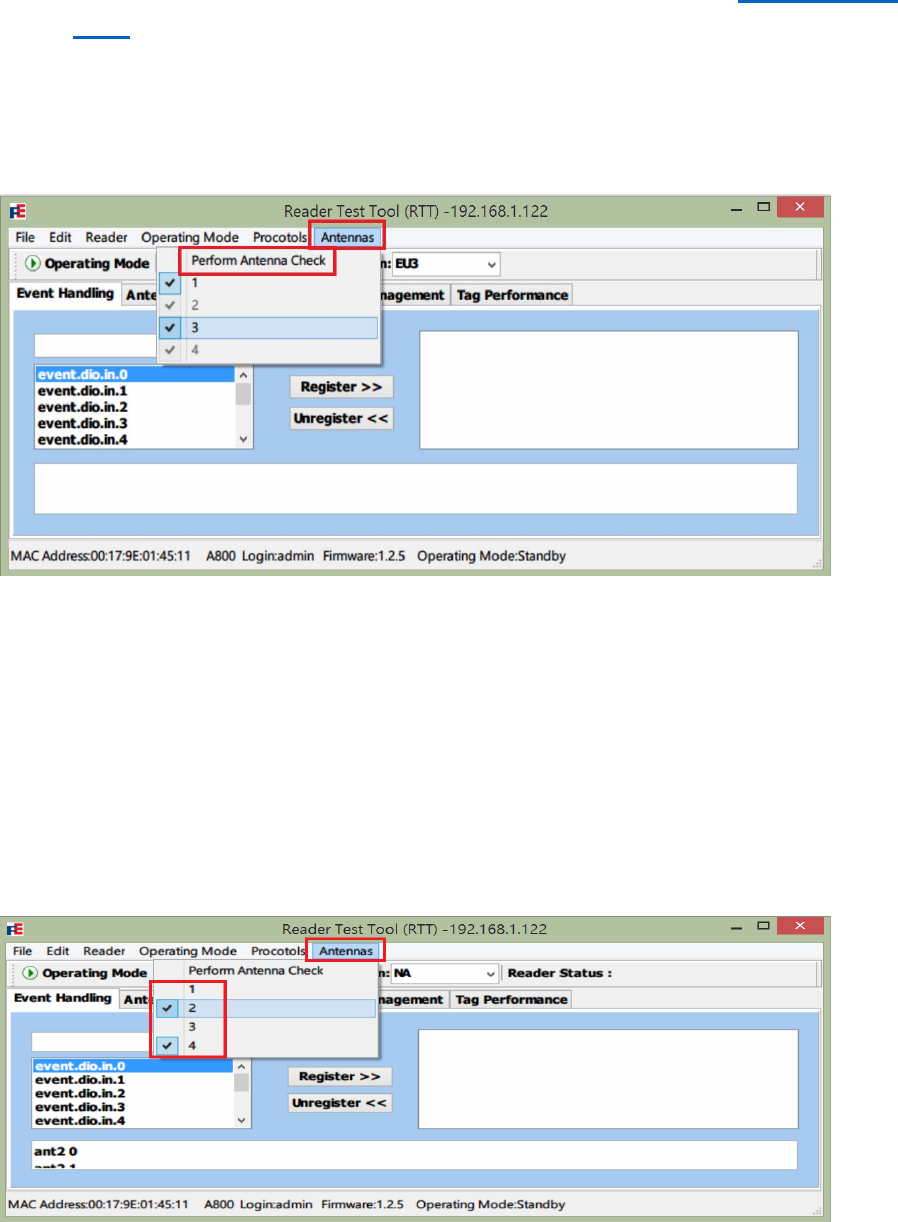
3.2.1 Antenna Setting
Antenna Selection:
1. Make sure the antennas were correctly connected. For detail, refer to 2.3 Installation
Notes to check antenna installation.
2. Select Antennas menu after logged in Reader Test Tool (RTT).
3. Click to run Perform Antenna Check to detect connected antennas. Detected antenna
port number will be shown in black and others in gray.
4. Manually check/uncheck the antenna ports to enable/disable antennas.
Troubleshooting: If the antenna cannot be detected after Step 3. Perform Antenna
Check (the connected antenna port index is still in gray), please follow operations below:
i Close RTT and RST.
ii Reboot the reader (Power down Æ wait by 5 seconds Æ power up Æ wait until
FAULT Red LED turns off).
iii Reopen RST. Launch and login into RTT
iv Select Antennas menu but do NOT launch Perform Antenna Check.
v Follow Step 4, manually check the connected ports and uncheck the empty
ports.
28
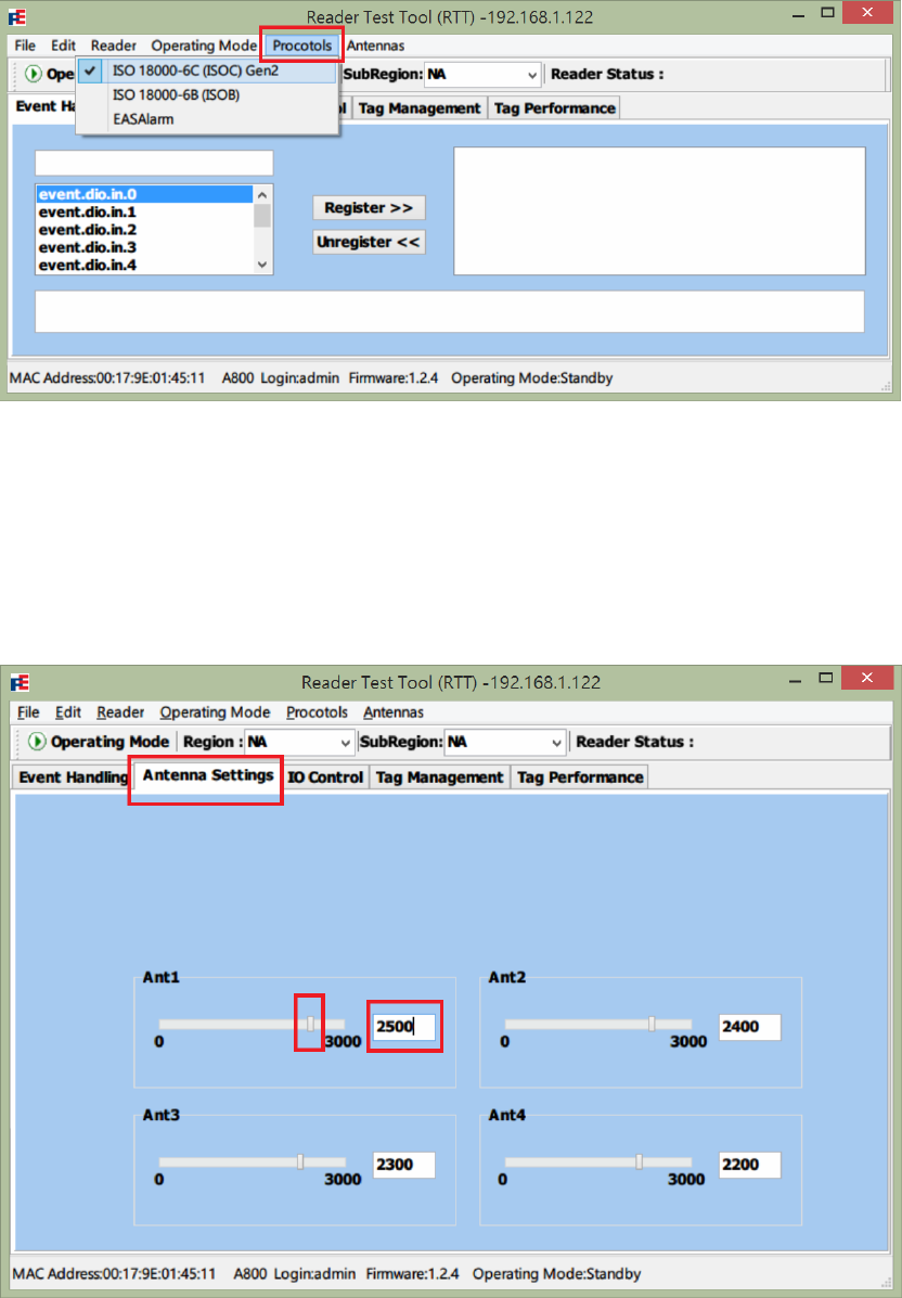
Protocol Selection:
1. Select Protocols menu after logged in Reader Test Tool (RTT).
2. Check ISO18000-6C (ISOC) Gen2.
Warning: YDT A800 currently support only ISO18000-6C (ISOC) Gen2 protocol.
Set antenna conducted power:
1. Select Antenna Settings tab in Reader Test Tool (RTT).
2. Adjust conducted power of Ant1~4 by dragging slide bars or giving numbers from 0 to
3000(0 to 30 dBm, if applicable) in the text fields.
3. Note that the above operations do NOT modify the profile setting, that is, the
29
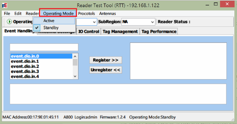
conducted power will be recovered with startup values after reader reboot.
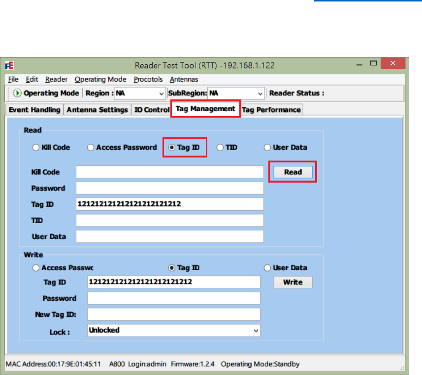
Select Operating Mode:
1. Select Operating Mode menu in Reader Test Tool (RTT).
2. Check on Active or Standby to change between 2 operating modes.
Active: Reader is continuously transmitting and detecting tags. The result is reported
through asynchronous events.
Standby: Reader enables RF transmitter when receiving a tag related command. After
the command process finish, the RF transmitter is turned off.
30
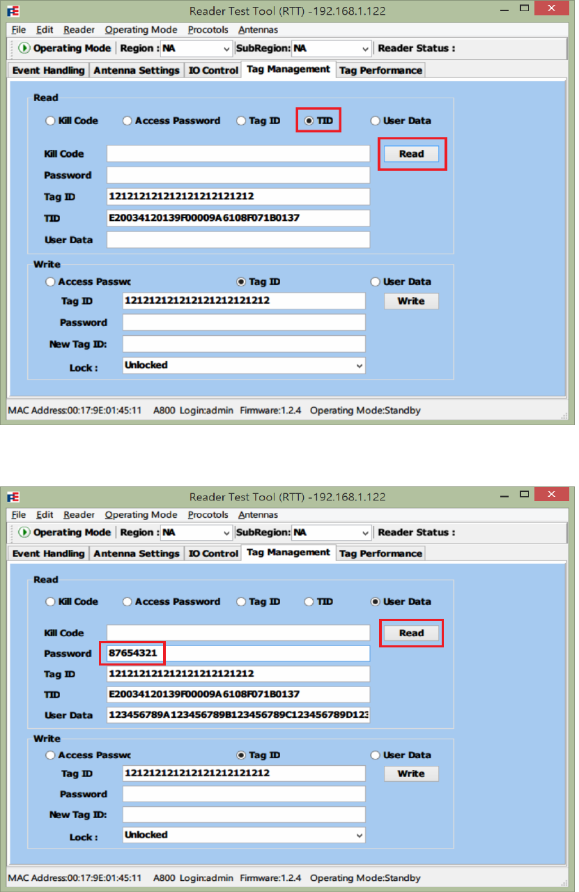
4. Keep the Tag ID (EPC) in the text field, select other fields including TID, User Data,
Access Password and Kill Code, and then press Read button to get the field values.
5. If a field was locked, the Password (Access Password) must be given to access the
field value. The password is an 8-digit hex string (4 bytes).
32
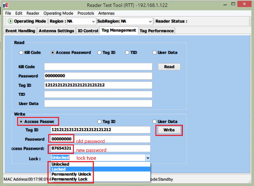
Set Access Password:
1. If a tag’s password has not been set, it can be extracted in the Read area. Default
access password is “00000000”.
2. In the Write area, select Access Password radio item.
3. Give Old Password, New Password.
4. Select Lock Type of a field data:
Locked: Password required to modify the field data.
Unlocked: Free read and write.
Permanently Unlock: Freeze a field in Unlocked state and cannot be locked.
Permanently Lock: Freeze a field in Locked state and cannot be unlocked.
5. Press Write button to apply the changes.
33
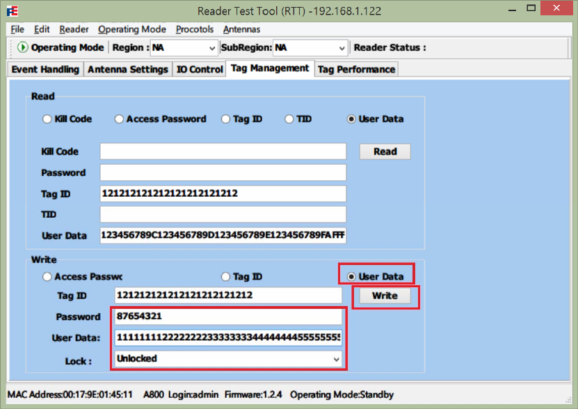
Write Tag Data:
1. In the Read area, scan the Tag ID (EPC) of a specific tag.
2. In the Write area, select Tag ID (EPC) or User Data field to be modified.
3. Give new data and lock type. If the field was locked, the Password must be given.
4. Press Write button to apply the changes.
Note: YDT A800 supports Tag ID (EPC) of 12 bytes (24 hex characters), TID of 12
bytes (24 hex characters), and User Data of 32 bytes (64 hex characters).
34
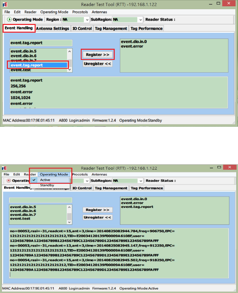
3.2.3 Event Handling
Register/Unregister an Event:
1. Select Event Handling tab after logged in Reader Test Tool (RTT).
2. The left side list shows all supported events; the right side list shows registered
events associated to the current session (channel id).
3. To register an event, select a specific event name on the left side. Press Register
button to make the event to be registered and then moved to the right list.
4. Set Operating Mode to Active to start transmitting and receive events.
5. To unregister an event, select an event name on the right side, and press Unregister
button.
35
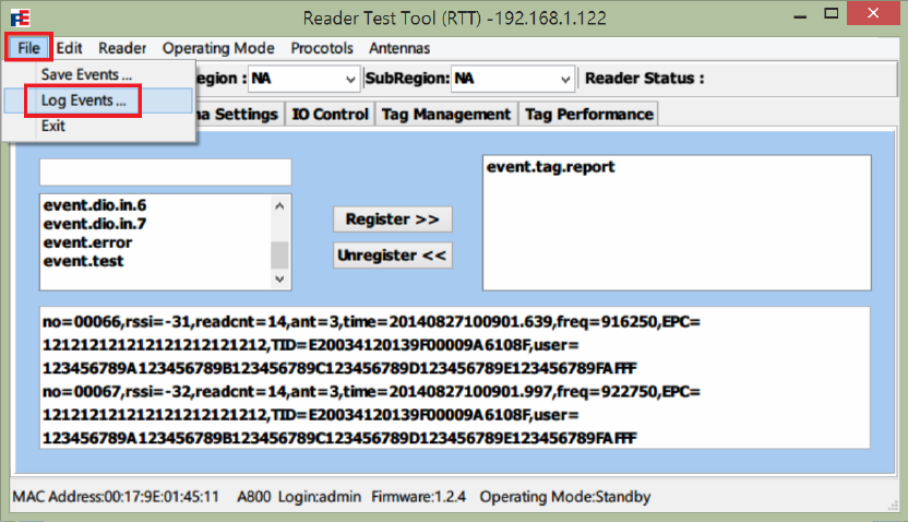
Get and Save Event Report:
1. Select File menu Æ Log Events. Browse and assign the report file name. Incoming
event log will be appended to the file.
2. Register events according to use case.
3. Select Operating Mode menu, and set operating mode to Active.
4. The asynchronous event report will be displayed in the text scrolling area, and also be
appended to the log file.
5. Switch Operating Mode to Standby to stop transmitting.
6. To store the log data displayed in the text area, select File menu Æ Save Events.
Browse and assign the log file name to save log data.
Warning: In step 6, Save Events only save the content in the text area for one time.
Future incoming log data will not be append to this file.
36
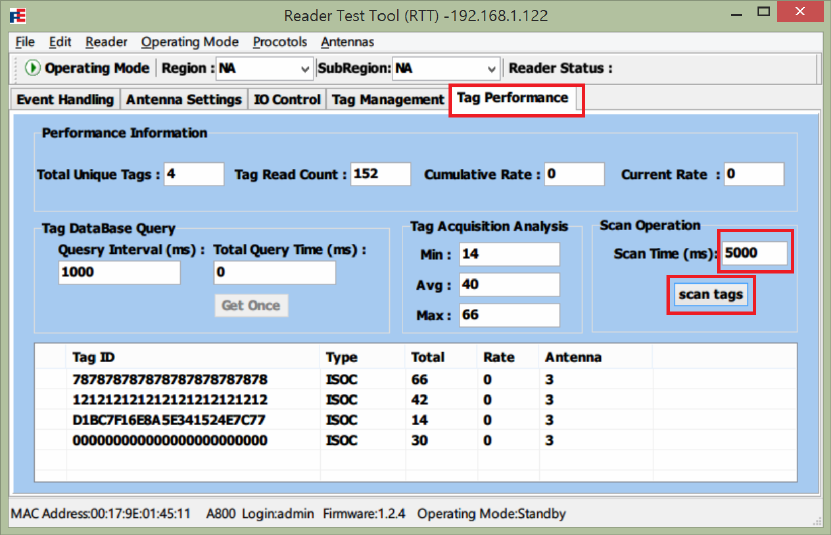
3.2.4 Tag Performance
Performance Test:
1. Select Tag Performance tab after logged in Reader Test Tool (RTT).
2. Enter the Scan Time (in milliseconds) value which is period of a test.
3. Press scan tags button to start a test.
4. After the test finished, performance data is displayed in the Performance information
and Tag Acquisition Analysis area, including:
Tag Unique Tags: Number of unique tags found.
Tag Read Count: Total number of tags read (including repeat reads)
Cumulative Rate: Cumulative read rate (tags/sec) during the test. Cumulative rate is
NOT available now.
Current Rate: Current read rate (tags per second). Current rate is NOT available
now.
Tag Acquisition Analysis: Minimum, maximum and average read count of each tag.
37
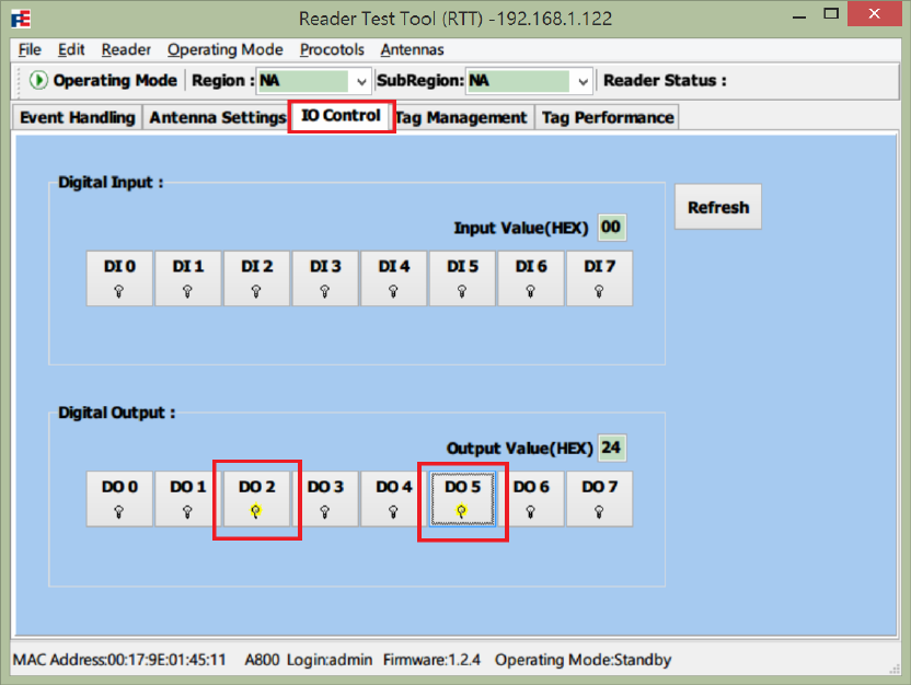
3.2.5 IO Control
Set Digital Output:
1. Select IO Control tab after logged in Reader Test Tool (RTT).
2. In the Digital Output area, check or uncheck the DO #0~7 buttons to set the 8-port
D-out value to high or low. DO#7 is for MSB and DO#0 is for LSB. The yellow light
bulb icon stands for high.
38
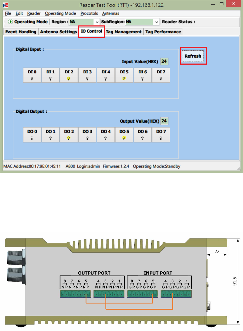
Read Digital Input:
1. Select IO Control tab in Reader Test Tool (RTT).
2. Press Refresh button to read Digital Input values.
3. In the Digital Input area, the DO#0~7 icons and the 2-digit hex string show values
of the 8-port digital input.
Simple IO Test:
1. Connect D-out ports to corresponding D-in ports.
2. Set Digital Output values in IO Control page.
3. Press Refresh button and check if Input values equals Output values.
39
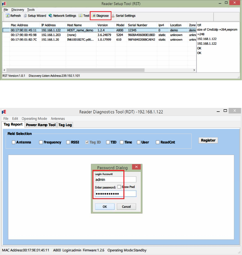
3.3 Reader Diagnose Tool (RDT)
The Reader Diagnostic Tool (RDT) is used to:
z Diagnose reader issues.
z Do adjustment on advanced and low level settings.
Open and login into the Reader Diagnostics Tool (RST):
1. In the list view of Reader Setup Tool (RST), select a YDT A800 Model.
2. Press Diagnose button to launch Reader Diagnostics Tool (RDT).
3. Login with Account and Password (default: admin/readeradmin) then press OK
button.
40

3.3.1 Tag Report
Choose specific fields for each tag report event:
1. Select Tag Report tab after logging in Reader Diagnostics Tool (RDT).
2. Select Operating Mode menu, change antenna Operating Mode to Standby.
3. Check or uncheck items in Field Selection to configure the report fields in tag
events.
4. Press Register button apply the changes. If success, an OK message will be
displayed in the text area.
Note: Any changes in Tag Report page does NOT modify the reader profile. Field
information will be restored in line with the startup values after reboot.
41
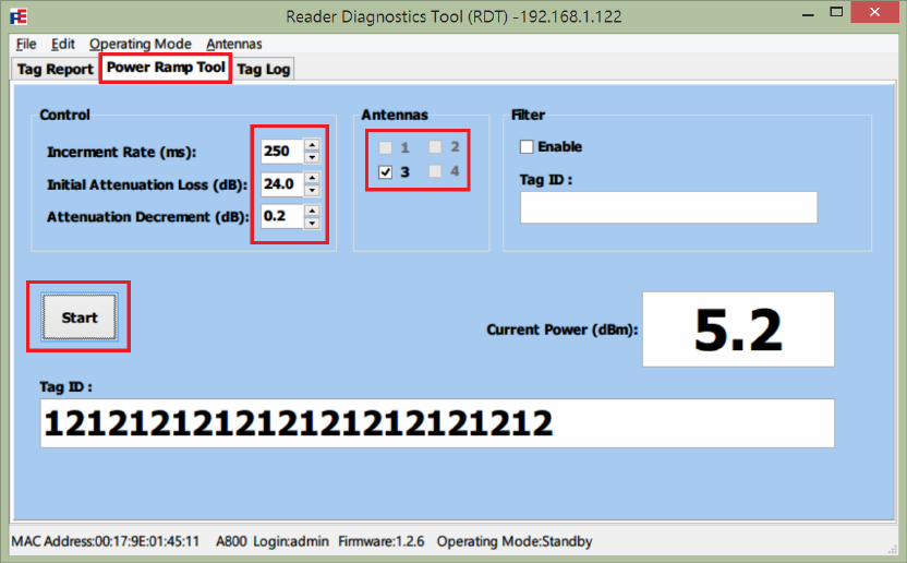
3.3.2 Power Ramp Tool
The Power Ramp Tool determines the minimum power to activate a tag and help determine
tag quality. The activation power level can help determine the read range at various
attenuation levels.
Perform a Power Ramp Analysis:
1. Select Power Ramp Tool tab after logging in Reader Diagnostics Tool (RDT).
2. In Antennas area, check on antenna indices to be activated.
3. In Control area, choose power ramp control parameters:
Increment Rate: Time period (in millisecond) of staying at each power level.
Initial Attenuation Loss: Initial attenuation level (in dB)
Attenuation Decrement: Step size of attenuation decrement.
4. Press Start button to perform power ramp analysis.
5. The result activation power will be displayed in Current Power grid.
42
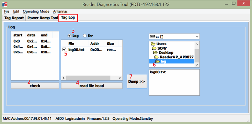
3.3.3 Tag Log
Dump Reader Logs:
1. Select Tag Log tab after logging in Reader Diagnostics Tool (RDT).
2. Press check button to scan log data section in reader.
3. Check on Log or Err radio item to select log type.
Log: Event records (tag report event, IO event)
Err: Error records. (antenna error)
CHECK error type
4. Press read file head button to extract the log file name.
5. Check on the extracted log file to be stored.
6. In the folder view on the right side, browse to a path to store log files.
7. Press Dump>> button to save log data into log file.
43