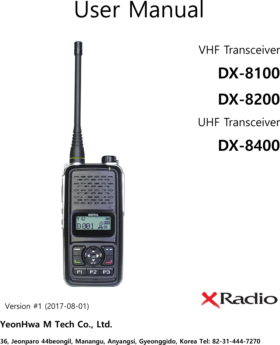
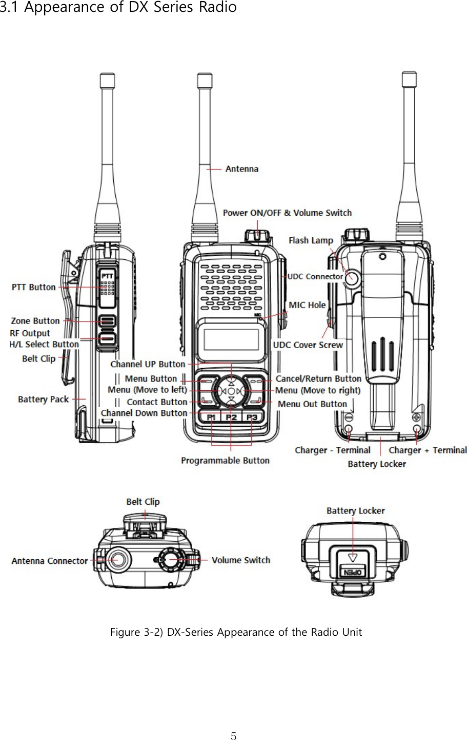
YEONHWA M TECH DX-8400 DMR(Digital Mobile Radio) User Manual

YEONHWA M TECH CO.,LTD DMR(Digital Mobile Radio)

User manual

  User Manual Version #1 (2017-08-01)                               YeonHwa M Tech Co., Ltd.   36, Jeonparo 44beongil, Manangu, Anyangsi, Gyeonggido, Korea Tel: 82-31-444-7270  VHF Transceiver DX-8100 DX-8200 UHF Transceiver DX-8400
  21. DX-Series Features DX-Series was developed with the user in mind to provide a compact and rugged design with features to  fit  multiple types  of  jobs such  as  military, firefighting,  construction  site,  industrial site and large retailers.     It works in dual (analog / digital) mode, compatible with existing analog radio and efficient as well in digital mode with clear voice quality, volume, call distance and usage time.    As follows:  32 Channels in 16 Zones 32 (1zone = Max 32 Channels)    512 Channel Capacity    5/1 Watt RF Power Setting  Text Messaging with inbox and outbox (within 40 letters), Max 10 sentences  Encryption Mode (ARIA 128, 192, 256.   LEA 128. 196. 256. AES128 256)  TX Interrupt  Lone Worker Mode  Scan    BCL / BCLO    Time-Out Timer (TOT)    Emergency / Siren  Built in Flash Lamp  Etiquette (Vibration)    Voice recording and playback  Mixed Channel Operation (Analog / Digital)  GPS (Option)  Five level VOX (Voice Operated Transmit)  Five level S.Q (Analog)  Remote Radio Stun / Kill / Revive  Clear speaker volume of 1Watt  UDC accessory connector for waterproof IP67    3Lines Mono LCD Display  Aluminum metal Frame Body    DC+7.4V Li-ion / 2,600mAH
  32. Specification 2.1 DX Series General Frequency Range   Frequency Stability Programmable Channels Channel Spacing Digital Vocoder Dimensions Weight Power Source Current Drain (maximum)     DX-8100 : 136~174 MHz DX-8200 : 216~224 MHz DX-8400 : 400 ~470 MHz ±1.5ppm (-30 to +60℃) 16 Zones / 32 Channels 12.5KHz AMBE++ 103mm(H) x 52mm(W) x 32mm(D)  280g   DC +7.4V Li-ion 2,600mAH Battery Receive mode, rated audio out – 420 (Audio Max) Transmit mode – 1,200mA Standby mode – 110mA Receiver Sensitivity Squelch Sensitivity Selectivity Spurious and Harmonic Rejection FM Hum and Noise Audio Output Power Audio Distortion Audio Response Input Impedance 0.25uV 12 dB SINAD 0.22uV 10dB SINAD 65dB (12.5KHz) 75dB 40dB (12.5KHz) 1 Watt across an 16-ohm load Less than 3% at rated output +1, -3 dB from 6dB per octave de-emphasis Characteristic from 300 ~ 3000Hz 50 ohms Transmitter RF Power Output Spurious and Harmonic FM Hum and Noise Audio Distortion Audio Frequency Response Output Impedance 5/1Watt 70dB 40dB (12.5KHz) 3% maximum with 1KHz modulation +1, -3dB from 6dB per octave pre-emphasis Characteristic from 300 ~ 3000Hz 50ohms
  43. DX Package Contents   * The components may be changed at the request of the buyer.                                                               Radio Unit                              Battery                  One Slot Charger                     Antenna                                                                                     Belt Clip                                Strap                            User Manual    Figure 3-1) DX-Series Main Package Contents  XB-2600 : 2,600mAH Li-ion Battery Pack XC-100D : One Slot Charger   XC-200D : Dual Slot Charger 423D-WS : 400~450MHz SMA Whip Antenna 460D-WS : 440~470MHz SMA Whip Antenna
  53.1 Appearance of DX Series Radio       Figure 3-2) DX-Series Appearance of the Radio Unit
  6 Figure 3-3) DX-Series Appearance of LCD  3.2 Button & LED Operations Button & LED  Operation Description Power ON/OFF  Turning the volume knob clockwise to power ON, volume up and turning the knob counterclockwise to power OFF, volume down.   Volume/Menu +/- Button Press +/- button to control the call audio. + button will volume up and – will volume down. In Menu status, it moves through list functions to choose from. Up/Down Button You can change the setting for the set channel. 32 channels can be input per zone. You can move to other list functions in the progress of menu. Zone Button  You can proceed to change the calling area set by the user in order. Menu/OK Button  Button for entering into Menu mode.   When entered into Menu mode, you can choose each list functions. Cancel/Return Button Press the button to return to previous item in menu. In the menu setting screen, it functions as cancel button. P1, P2, P3 Button Short press is Programmable Key.   Long Press of button more than 2 seconds is as follows: - P1 is to disable the keypad lock function - P2 is to turn Flash ON / OFF - P3 is to turn Etiquette (Vibration) ON / OFF Contact List Button  Button directly for Contact List. You can enter Private Contact, Private Call, Group Call or All Call.
  74. Basic Operations Please fully read the instruction manual before use. This manual provides convenient information related to radio operation.  4.1 Antenna Installation and Removal To attached the antenna connector, fasten the antenna clockwise.  To remove the antenna, rotate it counter-clockwise.   Figure 4-1) Antenna Installation and Removal   When installation of antenna, giving a strong pressure to the radio or pulling the antenna with a strong power from the radio can make a damage on the antenna connector, which may cause the radio to have a critical problem.
  84.2 Battery Installation and Removal Refer to the figure 4-2 and 4-3.    To remove the battery, push the locker and pull following the arrow direction.    To install the battery, slide up the battery towards the top of the radio as number 1 and push down as number 2 until battery latch is locked.    Figure 4-2) Battery Removal   Figure 4-3) Battery Installation
  94.3 Belt Clip Installation and Removal Refer to figure 4-4.  To attach belt clip to the radio, align its rails with the grooves in radio and slide the belt clip onto the mounting rails until it latches into place.  To remove belt clip from the radio, push up on tab of belt clip with flat bladed screw driver and at the same time, slide the belt clip towards the top of Radio.     Figure 4-4) Belt Clip Installation and Removal  4.4 External Accessory Connector Jack  Connect the external accessory as shown in the picture.    Fix the main unit and the accessory by aligning them and tighten the screw. To remove the accessory, loosen the fixed screw.
  10 Figure 4-5) External Accessory Jack  4.5 Charging the Battery RED lamp indicates the radio  is on the  charger (XC-200D) that the unit is  starting to  charge and the LED will illuminate GREEN when the charging is completed. Charger (XC-200D) is dual to charge both the main unit and the battery pack.  When  both  of  them  are  connected  to  the  charger,  the  front  radio  with  the  battery  will  be charged first and the batter pack later.   Figure 4-6) Charging the Battery
  115. Operation of DX Series   DX series Button Operations are as follows in figure 5-1.   Figure 5-1) DX Series Button Description  5.1 Power ON / OFF, Volume Switch Turning the volume switch knob clockwise to power ON and turning the knob counterclockwise to power OFF.    There will be a sound with a logo on LCD when turning ON the radio.   When  turning  the  knob  to  counter-clockwise,  you  will  hear  good-bye  and  the  radio  will  be turned OFF.  You can also control the Volume level with the knob. It volumes up when you turn it clockwise and volumes down when you turn it counter-clockwise.
  125.2 PTT Button The radio transmits messages when pressing PTT button. It receives messages when releasing the PTT button. In order to have clear sound when transmitting, it is recommended to speak around 5~10cm away from the MIC.  5.3 ZONE Button  When pressing Zone button, zone registered in the program will be selected in order. You can choose channel by using UP/DOWN button in selected zone.  5.4 Menu Button After pressing the menu button, you will see the menu listed below as figure 5-2. When pressing the left arrow button, it moves to the left. When pressing the menu button one more time while in the menu, it moves to detailed menu section of the selected one.  Figure 5-2) DX Series Menu
  13 Figure 5-2) DX Series Menu Tree   5.5 Channel Menu UP / Down Button Regularly UP / DOWN buttons are for the channel selection. In the menu screen, it moves through different functions (UP&DOWN).  5.6 Contact Button Press the  button to enter the contact list programmed into  the  radio  such  as Private, Group and All Call.  5.7 P1, P2, P3 Programmable Button Press of the buttons allow the enable and disable of programmed functions. Operational short press and long press (Over 2 seconds) are available.    You can set the function with short Key in PC program.   However, Long Key is defined in the radio itself.
  14When Keypad Lock is ON, key Lock is set automatically in 10 seconds when there is no press of buttons.  P1  is  to  disable  temporarily  the  keypad  lock  function  and  you  need  to  press  Long  Key  to unlock it.   It automatically locks again when you do not press the buttons in 10 seconds.  In  order  to  unlock  totally  the  keypad  lock,  go  to  the  menu-settings  and  select  OFF  in  the Keypad Lock menu.    P Button  Short Key  Long Key P1  Programmable  Key Lock ON / OFF(Temporarily) P2  Programmable  Flash Light ON / OFF P3  Programmable  Vibration ON / OFF  5.8 UDC EAR / MIC Jack UDC EAR/MIC Jack is used in the following cases: 1) When using external speaker MIC 2) When setting radios with CPS Program 3) When communicating with external terminals  5.9 LED Indication Status This  LED  is  a  lamp  indicating  the  current  status  of  the  Radio  and please  refer  to  the  below contents.  ① Normal TX: Red Lamp ② Normal RX: Green Lamp ③ Green lamp flickers when frequency matches but not the color code.   ④ Low Battery: Red Lamp blinks with “beep” sound.
  156. Charging the Battery   6.1 Safety Notes  1) DX-series receives power from high-performance Li-ion battery (XB-2600). Battery is safe of high performance and highly reliable.   When using the standard charger, it allows you to fully use the battery’s efficiency and life span.   The  charging  of  the  enclosed  radio  on  the  other  maker’s  charger  will cause damage to the battery and also a trouble.  2) Please charge the battery before using the radio for best performance and safety.   3) When you charge the battery that is installed in the radio, please turn off the radio first to charge the battery.   The  continuous  rapid  discharge  (For  example,  when  making  a  short circuit on the ‘+,-‘ terminals of battery by a metal substance) may make a fatal defect and the battery can be exploded as well as cause fire.    6.2 The Time of Charging   low  battery  voltage  may  reduce  communication  coverage  and  also  make  the  performance worse.  Please charge the battery in case of following: 1) When you think the performance of the radio has degraded. 2) When the red lamp on RX / TX LED blinks (every 0.5 seconds) during transmission or reception.   3) When the battery icon flickers. 4) When you hear the “beep” sound while the radio is in use.  6.3 How to Charge 1) Plug the adaptor of XC-200D charger in general power AC220V. 2) When charging the battery that is equipped with radio, please turn off the power of the radio and plug it in the charger.
  163) Even if charging it completed (green lamp lights shown), please charge about 30 more minutes for a full charge.  Status  LED Indication  Status LED Indication Charging  Red LED lights  Error Detection  Red LED flickers Complete Charging  Green LED lights  Keep Charging  Green LED Appears  7.  DX-Series Operation 7.1  Menu  Functions To enter the menu lists, press  button to have access.   There are 8 main menus and you can use the radio more conveniently if you use it according to your purpose and environment.  Figure 7-1) DX Series Menu Lists  ☞ Note) If the menu is not operated for at least 25 seconds after launch, the radio will revert to standby mode.  7.1.1 Contact Set the contact list by CPS program and press PTT button to call.   When you prefer to call another registered call, select from the list and press PTT button. It is available to register / delete the contact list by CPS (Customer Programing Software). You can find Individual, Group and All Call list by selecting the Contact menu.     Icons below are shown in the contact list. -  : Individual Call List (Individual Call , Send individual message)     -  : Group Call List   (Group Call , Send group message) -  : All Call List (Can use the terminals with the same channel and color code)
  177.1.2 Messages When you receive a message, the contents will be displayed on the LCD screen. When you are in the menu and the message is sent by someone, it will appear as an icon.  There are Quick Text, Inbox and Outbox function as follows:  1) Quick Text The preset messages are up to 10 in total by CPS Program. Each message can be written up to 40 letters and be edited.  You  can  see  the  quick  text  message  when  selecting  from  the  menu  and  select  the message and press  button to see it.   When you press one more time  button, the message will be sent to the terminal.    2) Inbox Stores  up  to  10  receives  text  messages;  when  the  received  messages  exceed  10,  the oldest message is cleared and the newest incoming message is registered. When you choose messages stored in the list, you can view the received messages. You can also delete the received messages by selecting all delete menu.  3) Outbox Stores  up to  10  outgoing  text  messages;  when  the  outgoing  messages  exceed  10,  the oldest message is cleared and the newest send message is registered.   When you choose messages stored in the list, you can view the sent messages. You can also delete the sent messages by selecting all delete menu.   7.1.3 Call Logs The function allows the viewing of incoming and outgoing calls from individuals only. The Group and All call records are not saved. The contents are managed in the same manner as Inbox / Outbox of the messages.
  181) Inbox Call records in the inbox can be saved up to 10.   You can also see the caller ID.   Stores  up  to  10  receives  calls;  when  the  received  ones  exceed  10,  the  oldest  call  is cleared and the newest incoming call is registered. You can also delete the received records by selecting all delete menu.  2) Outbox Stores  up  to  10  receives  calls;  when  the  received  ones  exceed  10,  the  oldest  call  is cleared and the newest outgoing call is registered. You can also see the caller ID.   You can delete the sent records by selecting all delete menu as well.  7.1.4 Record This function is used to record the content of incoming and outgoing calls.   You can delete all when the recorded contents are unnecessary. Up to 63 conversations / recordings can be stored with each recording limited to 2 minutes and 30 seconds.  Turn ON or OFF the setting in the menu when you need this function.    In the state that the encryption function is selected, only the call with the encryption mode can be heard in normal recording and call with no encryption mode cannot be heard.  7.1.5 Scan Channels set in the scan list can be scanned in order when the Scan function is ON. When there is used channel while scanning, it stops at that channel and receives the contents. When wanting the call while scanning, use the CPS Program.  1) Scan ON/OFF This  function  provides  the  ability  to  turn  scan  ON/OFF  and  review  the  scan  list  as programmed into the radio via the Program.
  19 2) Scan List You can set the scan list via CPS Program.  7.1.6 ZONE Up to 16 zones (with up to 32 channels per zone) can be programmed into the radio via CPS program.  7.1.7 Setting This function allows the changes to the settings of the radio status.   There  are  Power  level,  Encryption,  Voice  Operated  Transmit  (VOX),  Lone  worker,  BCL/BCLO, Keypad lock, Tones, LCD Backlight, LCD Contrast/Brightness, LED control, Language etc.  1) TX Output This function sets the power transmitting level at high or low.  2) Voice Encryption This is a feature to encrypt the incoming and outgoing voice. Voice Encryption function can only be performed from digital channel to each channel. Voice Encryption code is set via CPS Program. Encryption code can be set from 0 to 65535.  3)   VOX VOX function allows transmitting voice without pressing the PTT button. VOX sensitivity level is adjusted from 1 to 5 and can be set by users via CPS program.  4) Lone Worker This function can inform others about your safety within the time set in the menu. Setting time is from 1 minute to 100 minutes
  205) BCL / BCLO This function prevents interference when the channel is busy and limits the TX. BCL : If the current channel is busy, the transmission is prohibited. BCLO : The transmission is done regardless of the busy status of the channel.  6) Keypad Lock This function locks the keypad to prohibit the accidental press of keys and buttons by the users. When Keypad lock is ON, all keys and buttons are locked except the PTT button, the   emergency button and power ON/OFF.    Press the   key for 2 seconds to temporarily unlock the keypad for 25 seconds. Then, the keypad will be locked again.  To unlock the keypad, go to the setting and select Keypad Lock and changed the status to OFF.  7) Tones This function enables or disables the tones associated with key and button presses. Only ON/OFF setting is allowed with the radio itself. The details can be set through CPS program.    8) LCD Backlight This function allows the backlight of the LCD to be turned ON/OFF.  9) LCD (Contrast/Brightness) This function is to adjust the contrast/brightness of from 1 to 7.  10)   LED Control This function is to set the enable or disable the radio LED status.   You can set it with CPS program the details.
  2111)   Language This function is to select the language by the user.    7.1.8 Radio Info This shows all the info of the radio.  8. Safe Operation 8.1 Precautions   Do not remove the antenna from the radio or do not transform the antenna or do not make any changes on the antenna. The strong electronic wave to be  emitted  from  the  radio  can  have  an  effect  on  the  performance  of  the radio and can cause the radio to have a defect.   Do  not  use  accessories  (such  as  rechargeable  battery,  adaptor,  external speaker microphone  and  earphone etc.) from  the other makers,  which can cause defect on battery and malfunction or a defect on the radio.   Do  not  disassemble  or  reorganize  the  radio.  The  disassembly  or reorganization  will  cause  a  defect  or  malfunction  on  the  radio.  It  will  be impossible  to  repair  afterwards.  There  will  also  be  a  punishment  made  by the Radio Waves Act.   Do not use other frequency except for the permitted frequency in order not to be punished by the Radio Waves Act.   •  Do not give an excessive shock to the radio. •  Do  not  place  the  radio  where  the  direct  sunlight  and/or  the  high temperature occurs..   •  If  the  radio  is  placed  for  a  long  time  in  a  car  in  summer,  the  hot temperature in the car may cause explosion of battery. •  Do  not  make  a  damage  to the  battery by  a sharp  substance  and/or  an excessive shock.
  228.2 Influences on the Operations of Radio or Other Equipment  The radio emits a strong electronic wave, which may have an effect on the operation of other equipment and also can be influenced by the other devices.   Please turn off the radio before boarding on the airplane. When using the radio in the airplane, please follow the rules or the instructions of the flight attendants.   In  case  of  the  area  that  medical  equipment  are  being  used,  please  use  the  radio after discussion with the equipment producer or the related doctor.   Please do not use the radio at the place where computer or other electric/electronic devices are being used.  The strong electronic wave from the radio can have an effect on the equipment.  9. Safety Notes Please make sure to read the followings above for safe and effective use of the radio.   •  Please keep the radio away at least 1 inch from the body. •  If the outside surface of antenna gets stripped out, it can make a burn on the skin. •  If you contact a conductive metal to battery terminal, a heat can be made and it may cause fire, explosion and burn. Especially, please be careful when putting the battery in a pocket or a bag. •  When  using an earphone, please do not  listen to the sound at a  high level. The high sound may have a bad effect on your ear.    •  After setting the volume of the radio at a low level, please adjust the volume step by step to the level you want. A sudden high sound may bring a bad damage to the ear or the heart. •  Please  do  not  remove,  replace,  charge  or  discharge  the  battery  at  a  dangerous area since it may cause explosion or fire by an electrical spark. •  At the area where an electromagnetic force can be made, please make sure to turn off the power of the radio.
23Warranty Statement Thank you for purchasing DX-8000 Series. 1. This product has passed strict quality control and testing process by YeonHwa M Tech.2. Warranty is one year from the day of release.•When  there  is  malfunction  of  the  product  under  normal  operating  conditions  duringthe warranty period, your authorized dealer and the service center will repair it free ofcharge.3. Service fees will be charged for the following cases:• When performance failed, malfunction or damaged after the warranty period.• When the product is damaged due to user’s mishandling or improper operation.•When the product is damaged due to fire, pollution, earthquakes and any other naturalor unnatural conditions, accidents etc.• Malfunction by not keeping the notices written in the user manual.• Malfunction by not using the appointed adaptor.•When the product is damaged due to user’s modification, attempts of repairing ratherthan the appointed service center.4. Product Check ListModel Name  DX-8000 Series Serial No. Purchase Date Purchaser Name Address  ※  Please fill out this check list when purchasing the product.  YeonHwa M Tech Co., Ltd. 36, Jeonparo 44beongil, Manan-gu, Anyang-si, Gyeonggi-do, Korea 14086  TEL: 82-31-444-7270 FAX: 82-31-444-7271
24 1. WarningThis device complies with Part 90 of the FCC Rules. Operation is subject to the following two conditions: (1) this device may not cause harmful interference, and (2) this device must accept any interference received, including interference that may cause undesired operation. changes or modifications not expressly approved by the party responsible for compliance could void the user's authority to operate the equipment. NOTE: This equipment has been tested and found to comply with the limits for a Class B digital device, pursuant to Part 90 of the FCC Rules. These limits are designed to provide reasonable protection against harmful interference in a residential installation. This equipment generates, uses and can radiate radio frequency energy and, if not installed and used in accordance with the instructions, may cause harmful interference to radio communications. However, there is no guarantee that interference will not occur in a particular installation. If this equipment does cause harmful interference to radio or television reception, which can be determined by turning the equipment off and on, the user is encouraged to try to correct the interference by one or more of the following measures: -- Reorient or relocate the receiving antenna. -- Increase the separation between the equipment and receiver. -- Connect the equipment into an outlet on a circuit different
25 from that to which the receiver is connected. -- Consult the dealer or an experienced radio/TV technician for help. NOTE: This device and its antenna(s) must not be co-located or operation in conjunction with any other antenna or transmitter. RF Exposure Statement To maintain compliance with FCC’s RF Exposure guidelines, This equipment should be installed and operated with minimum distance of 0mm the radiator your body.   This device and its antenna(s) must not be co-located or operation in conjunction with any other antenna or transmitter. Changes or modifications to this unit not expressly approved by the party responsible for compliance could void the user’s authority to operate the equipment. RF Exposure Information:   The SAR limit of USA (FCC) is 1.6W/kg averaged over one gram of tissue. Device Types (FCC ID: VSODX-8400) has also been tested against this SAR limit. The highest SAR value reported under this standard during product certification for use when properly worn on the Face-held is 0.868W/kg and for body-worn is 2.76W/kg. Simultaneous RF exposure is 3.628W/Kg. This device was tested for typical body‐worn operations with the back of thehandset kept 0mm from the body.To maintain compliance with FCC RF exposure requirements, use accessories that antain a 5mm separation distance between the user's body and the back of thehandset. The use of belt clips, holsters and similar accessories should not containmetallic components in its assembly.
26 The use of accessories that do not satisfy theserequirements may not comply with FCC RF exposure requirements, and should beavoided. The use of belt clips, holsters and similar accessories should not contain metallic components in its assembly.   The use of accessories that do not satisfy these requirements may not comply with FCC RF exposure requirements, and should be avoided.

Navigation menu