YEONHWA M TECH MD-400D UHF Transceiver User Manual
YEONHWA M TECH CO.,LTD UHF Transceiver
User Manual
User Manual
VHF Transceiver
MD-100D
UHF Transceiver
MD-400D

Version #1 (2017-08-01)
YeonHwa M Tech Co., Ltd.
36, Jeonparo 44beongil, Manangu, Anyangsi, Gyeonggido, Korea Tel: 82-31-444-7270
MD-400D User Manual
1. MD-420D Digital RF Modem Specification
The MD-Series standardized the specifications of the instrument exterior and connectors so
that the digital RF modem can maintain compatibility with existing analog modems.
When using the digital mode, it is very efficient with the existing analog problems such as
data error, clean sound quality and volume, call distance, usage time
MD-Series Specification is as follows:
▪ Usage frequency VHF : 136~174MHz, UHF : 400~470MHz
▪ 1 Zones 32 channels selectable (1zone = Max 32 channels)
▪ Total 32 channels can be configured
▪ 5/1 Watt RF Power
▪ Encryption is available as option (AES128, 256)
▪ 5 level S.Q selectable (Supports Analog).
▪ Remote Radio Stun / Kill / Revive
▪ Available to connect speaker of 1Watt
▪ Data rate in wireless section : 9,600bps
▪ RS-232C communication rate : Standard 115,200bps(Change available according to
program
setting)
▪ Add AT Command for user convenience
▪ User friendly for enabling PC based modem Control GUI Software
▪ Aluminum metal Frame Body
▪ Service connector : DE-15 pin Female Connector
▪ Power supply : DC +9.0~DC+24V
2. Specification
2.1 MD-Series Specification
General
Frequency Range
Frequency Stability
Programmable Channels
Channel Spacing
Digital Vocoder
Dimensions
Weight
Power
Source
Current Drain (maximum)
MD
-100D : 136~174 MHz
MD
-400D : 400 ~470 MHz
±1.5ppm (
-30 to +60℃)
1 Zones / 32 Channels
12.5KHz
AMBE++
103mm(H) x 52mm(W) x 32mm(D)
280g
DC +9.0 ~ +24V
Receive mode, rated audio out
– 420 (Audio Max)
Transmit mode
– 1,200mA
Standby mode
– 110mA
Receiver
Sensitivity
Squelch Sensitivity
Selectivity
Spurious and Harmonic Rejection
FM Hum and Noise
Audio Output Power
Audio Distortion
Audio Response
Input Impedance
0.25uV 12 dB SINAD
0.22uV 10dB SINAD
65dB (12.5KHz)
75dB
40dB (12.5KHz)
1 Watt across an 16
-ohm load
Less than 3% at rated output
+1,
-3 dB from 6dB per octave de-emphasis
Characteristic from 300 ~ 3000Hz
50 ohms
Transmitter
RF Power Output
Spurious and Harmonic
FM Hum and Noise
Audio Distortion
Audio
Frequency Response
Output Impedance
5/1Watt
70dB
40dB (12.5KHz)
3% maximum with 1KHz modulation
+1,
-3dB from 6dB per octave pre-emphasis
Characteristic from 300 ~ 3000Hz
50ohms
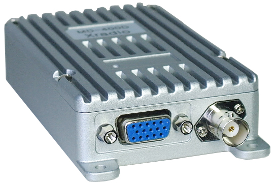
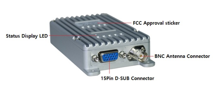
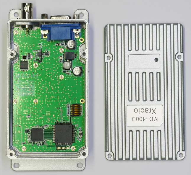
3. MD Series Components
3.1 Equipment name
* Components may differ according to the request of buyers.
Figure 3-1) MD-400D Series Component
3.2 Status Display LED
This is LED which displays the equipment status.
The main status display is as follows:
① Red color when normal transmission
② Green color when normal receive
4. How to use MD-400D Series
4.1 Message transmission and receive tools
You can send and receive messages through the AT Command, but the PC tool is provided
to make it easier to use.
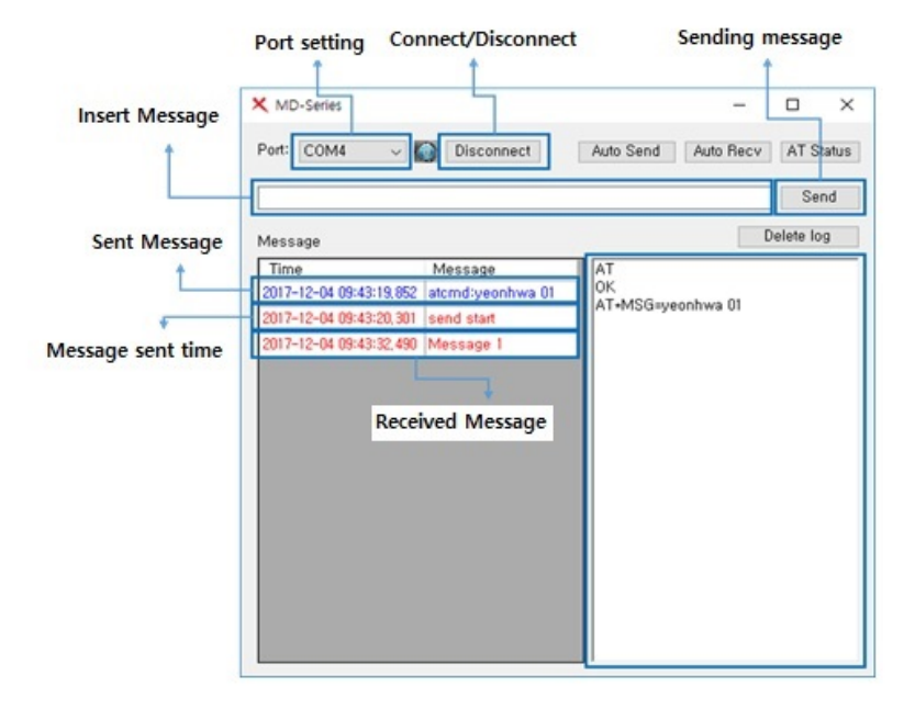
Figure 4-1) Message tool
4.1.1 Messages
It is possible to send and receive messages between the modem and the modem, and between
the modem and the terminal. By providing the PC interface as above, convenient configuration is
possible. You can configure the file or database connection to store additional messages.
Since it is based on PC, it can be saved as much as the capacity of the PC can be allocated, so it
can be seen that the capacity is not limited.
4.1.2 Basic Protocol
Supports an ACK message to determine whether the opponent terminal has received. When a
message is sent, the receiving terminal automatically sends an ACK message. When the message
is received, the other terminal informs the receiving terminal that the message has been received
normally.
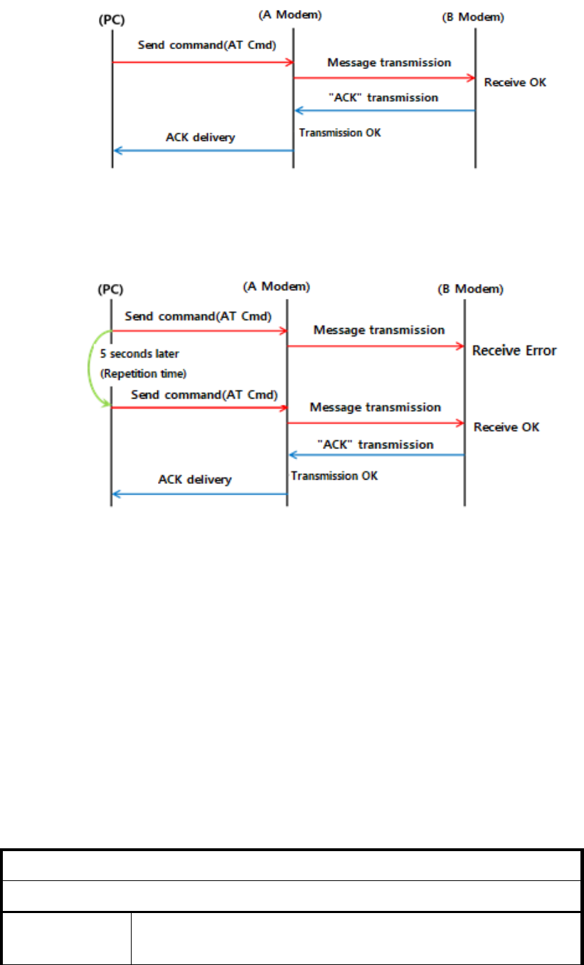
Figure 4-2) Normal Message Transmission and Receive Method
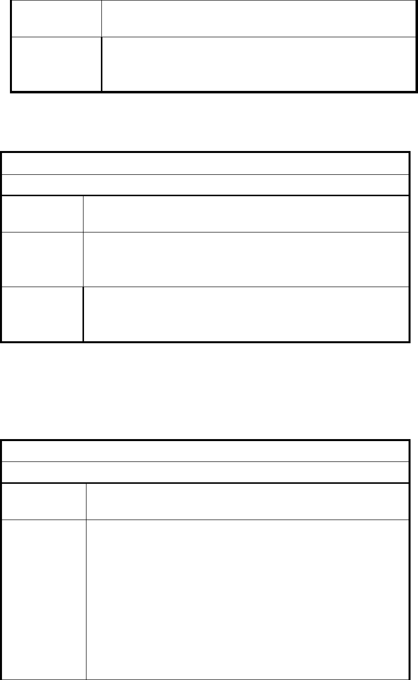
Figure 4-3) Action on Message Transmission Error
If an error occurs in the delivery of the message, the specified number of retries will be retransmitted
after 5 seconds.
Finally, there is no format restriction of characters, and it supports messages of up to 80 characters.
4.1.3 AT Command
Use AT Command to set the status of the transceiver(radio) or to use the function.
After connecting the serial port, use the terminal program. The basic speed is 115,200 bps.
1) Modem version information verify command (VERSION)
Description
Command to verify the modem version information
Query
Answer
1. AT*VERSION
*VERSION:<value1>
Parameters <value1>
S/W Version
Example AT*VERSION
*VERSION:YEONHWA Modem v1.0
OK
2) Modem Status verify command (CHKSTAT)
Description
Command to verify modem status
Query
Answer
2. AT*CHKSTAT
*CHKSTAT:<value1>
Parameters <value1>
STAT OK – Normal status
STAT ERROR – Error status
Example AT*CHKSTAT
*CHKSTAT:STAT OK
OK
3) Modem information verify command (MINFO)
Description
Command to verify modem information
Query
Answer
3. AT*MINFO
*MINFO:<value1>,<value2>,<value3>,<value4>
Parameters <value1>
Channel number
<value2>
Frequency
<value3>
Call ID
<value4>
Group ID
Example AT*MINFO
*MINFO:1,440.000,1,1
OK
4) Modem Reset (RESET)
Description
Command to reset modem
Query
Answer
AT*RESET
RESET
Parameters <value>
Reset the modem
Example AT*RESET
RESET
Going down terminal…
5) Sending Message (MSG)
Description
Command use when sending message
Query
Answer
AT*MSG=<value>
MSG OK
Parameters <value>
Message to be sent
Example AT*MSG=TEST
MSG OK
6) Receiving Message (RMSG)
Description
Command use when receiving message
Answer
RMSG=<value>
Parameters
<value>
Receive message
Example
RMSG=TEST
7) Check channel list (CHLIST?)
Description
Command to verify when receiving message
Answer
AT*CHLIST?
Parameters
CHNUM: <value> : Current channel number
Whole channel number: Classified channel number, RX
frequency, TX frequency
… <repeat>
Example
CHNUM:01
01:0:ANA,RX:441000000,TX:441000000
02:1:ANA,RX:423600000,TX:423600000
03:2:ANA,RX:423612500,TX:423612500
04:3:ANA,RX:423625000,TX:423625000
05:0:DMR,RX:440000000,01,TX:440000000,01
06:1:DMR,RX:423200000,01,TX:423200000,01
07:2:DMR,RX:423212500,02,TX:423212500,02
08:3:DMR,RX:423225000,03,TX:423225000,03
09:4:DMR,RX:423237500,04,TX:423237500,04
10:5:DMR,RX:423250000,05,TX:423250000,05
11:6:DMR,RX:423262500,06,TX:423262500,06
12:7:DMR,RX:423275000,07,TX:423275000,07
13:8:DMR,RX:117440512,07,TX:117440512,07
14:9:DMR,RX:117440512,07,TX:117440512,07
15:10:DMR,RX:117440512,07,TX:117440512,07
16:11:DMR,RX:117440512,07,TX:117440512,07
OK
8) Channel setting (CHSET)
Description
Command to verify when receiving message
Answer
AT*CHSET=<value>
Parameters
<value>
Channel number
Example
AT*CHSET=3
CH:03
OK
5. For Safe Operation
5.1 Precautions
Do not remove the antenna from the radio or do not transform the antenna or
do not make any changes on the antenna. The strong electronic wave to be
emitted from the radio can have an effect on the performance of the radio and
can cause the radio to have a defect.
Do not use accessories (such as rechargeable battery, adaptor, external
speaker microphone and earphone etc.) from the other makers, which can
cause defect on battery and malfunction or a defect on the radio.
Do not disassemble or reorganize the radio. The disassembly or reorganization
will cause a defect or malfunction on the radio. It will be impossible to repair
afterwards. There will also be a punishment made by the Radio Waves Act.
Do not use other frequency except for the permitted frequency in order not to
be punished by the Radio Waves Act.
• Do not give an excessive shock to the radio.
• Do not place the radio where the direct sunlight and/or the high temperature
occurs..
• If the radio is placed for a long time in a car in summer, the hot temperature in
the car may cause explosion of battery.
• Do not make a damage to the battery by a sharp substance and/or an
excessive shock.
5.2 Influences on the Operations of Radio or Other Equipment
The radio emits a strong electronic wave, which may have an effect on the operation of other
equipment and also can be influenced by the other devices.
Please turn off the radio before boarding on the airplane.
When using the radio in the airplane, please follow the rules or the instructions
of the flight attendants.
In case of the area that medical equipment are being used, please use the
radio after discussion with the equipment producer or the related doctor.
Please do not use the radio at the place where computer or other
electric/electronic devices are being used. The strong electronic wave from the
radio can have an effect on the equipment.
6. Safety Notes
Please make sure to read the followings above for safe and effective use of the radio.
• An indication of the maximum antenna gain permitted to ensure compliance.
this would be 1.5 dBi.
• At the area where an electromagnetic force can be made, please make sure
to turn off the power of the radio.
• The user should limit the operation to 50%.
• RF Safety Distance of 13.21
cm for Occupational/Controlled Exposure and
29.46 cm for General Population/Uncontrolled Exposure which met the FCC
Limits.
• Be careful that if the outer surface of the antenna is peeled off, there is a
danger of a topic.
7. Handling Caution
• Any changes or modifications not expressly approved by the party responsible for compliance with
the FCC regulations could void the user's authority to operate the equipment.
• It is forbidden to install or operate the device other than the responsible person (licensed person).
•The user manual is included in the box.
•How to use and install the product is shown in the figure.
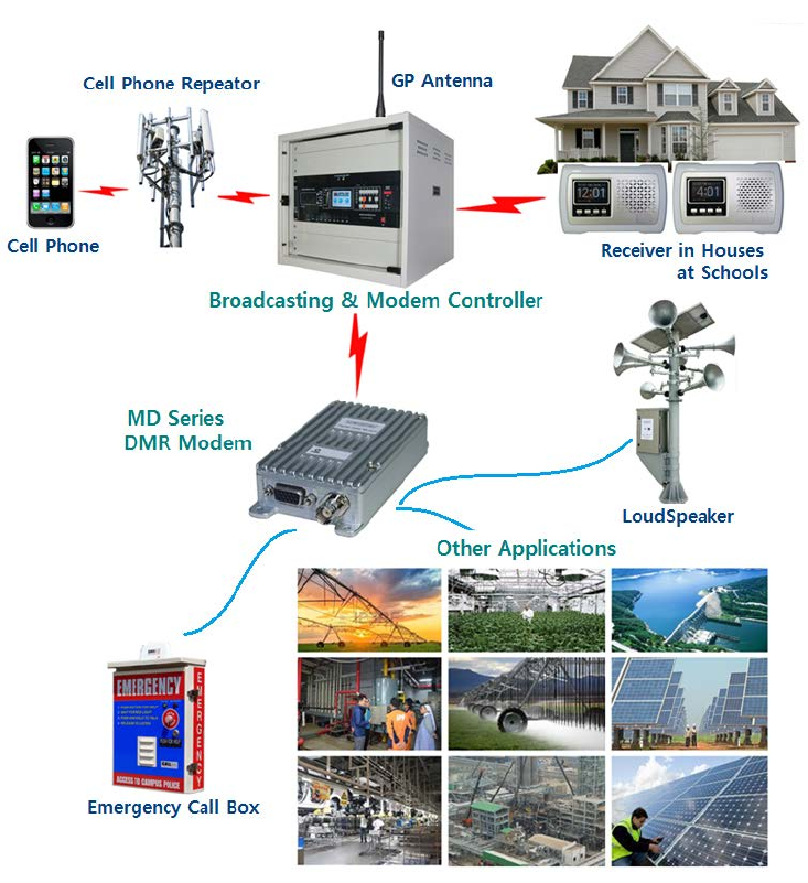
8. Usage
Application
▪ Water/Waste Treatment
▪ Plants Oil and Gas Field, SCADA
▪ Security/Alarm System
▪ Gate Systems, Remote Controls
▪ Commercial Sign Control
▪ Automatic Vehicle Location
▪ Murphy/Kill Switches
▪ Weather Monitoring
▪ Irrigation Systems
▪ Emergency Call Boxes
▪ Low Power Repeaters
Warranty Statement
Thank you for purchasing MD-100D/ MD-400D Series.
1. This product has passed strict quality control and testing process by YeonHwa M Tech.
2. Warranty is one year from the day of release.
• When there is malfunction of the product under normal operating conditions during the
warranty period, your authorized dealer and the service center will repair it free of charge.
3. Service fees will be charged for the following cases:
• When performance failed, malfunction or damaged after the warranty period.
• When the product is damaged due to user’s mishandling or improper operation.
• When the product is damaged due to fire, pollution, earthquakes and any other natural or
unnatural conditions, accidents etc.
• Malfunction by not keeping the notices written in the user manual.
• Malfunction by not using the appointed adaptor.
• When the product is damaged due to user’s modification, attempts of repairing rather than
the appointed service center.
4. Product Check List
Model Name
MD-Series
Serial No.
Purchase Date
Purchaser
Name
Address
※ Please fill out this check list when purchasing the product.
YeonHwa M Tech Co., Ltd.
36, Jeonparo 44beongil, Manan-gu, Anyang-si, Gyeonggi-do, Korea 14086
TEL: 82-31-444-7270
FAX: 82-31-444-7271