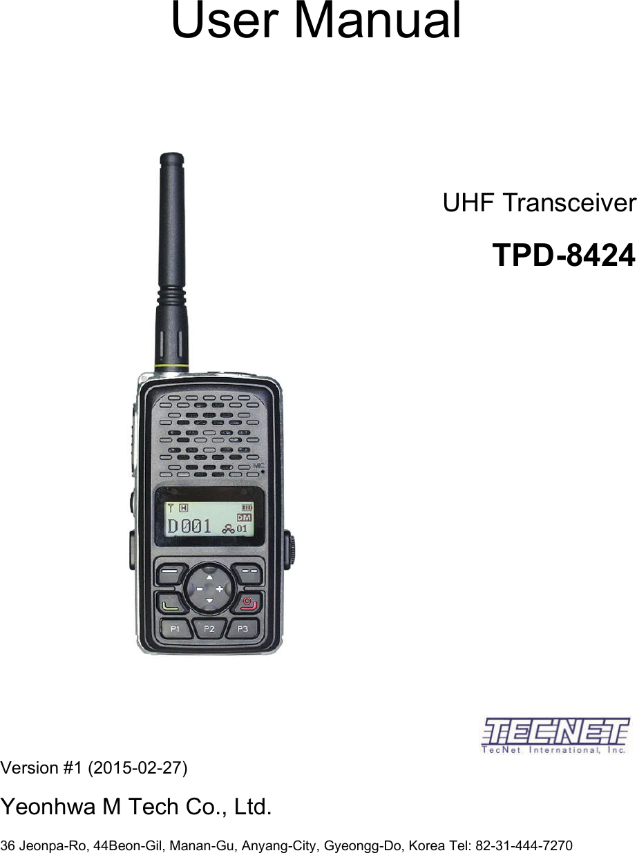
YEONHWA M TECH TPD-8424 UHF Transceiver User Manual
YEONHWA M TECH CO.,LTD UHF Transceiver
UserManual.wiki
>
YEONHWA M TECH
>
TPD 8424 User Manual
User Manual
Navigation menu
Upload a User Manual
Namespaces
Wiki Guide
HTML
PDF
Info
Views
User Manual
Discussion / Help
Navigation
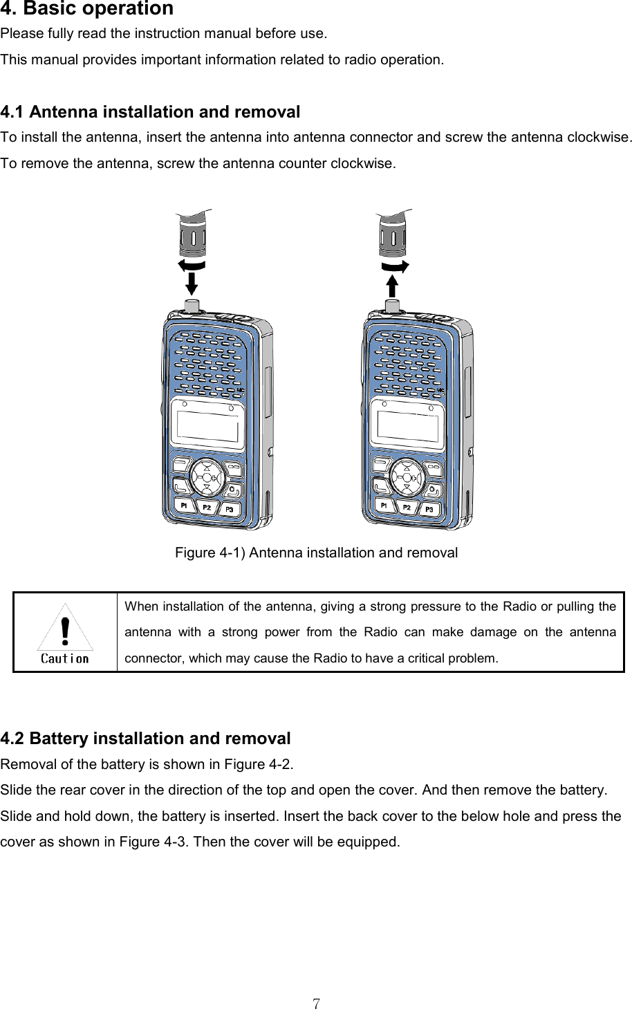
![6 Figure 3-3) LCD Indication of TPD-8424 Series Radio 4.1 Basic Button Operations Button Operation Description Power ON/OFF Press and hold the power button for 2 seconds, the device power is turned ON. When you press the power button for 2 seconds during use, the power is OFF. Volume/Menu+/- Button +/- Button can adjust the call sound by using, and if you press the [+] button, the sound will be increases if you press the [-] button, the sound will be smaller. In the menu, you can move to the menu item. Up/Down Button You can change the settings of the Channel that have been set. You can enter 32 Channel per the call zone (Zone). In the progress of the menu, you can move the menu item. Zone Button You can change the order of the call zone that you set. Menu/OK Button The button to enter the menu. When you enter the menu, you can make a choice of each item. Cancel/Return Button Using the Button, it will return to the menu on the one stage. In the menu setting screen, and run the cancellation of the function. P1, P2, P3 Button When operating in the Short Key, it is a Programmable Key. When operating in Long Key (press for longer than 2 seconds); - P1 is the unlocking button against lock function. - P2 is Flash On / Off - P3 is Etiquette On / Off Contact List Button The button can be entered directly on the Contact List. By entering the Contact List you can proceed with individual calls, group calls, total calls.](https://usermanual.wiki/YEONHWA-M-TECH/TPD-8424/User-Guide-3089578-Page-6.png)