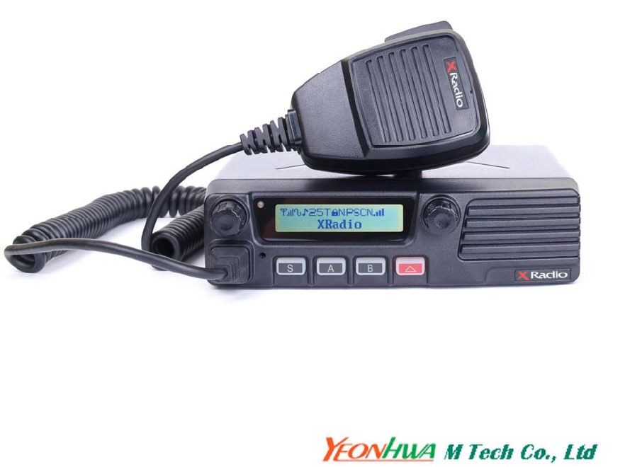
YEONHWA M TECH XM-1000 FM TRANSCEIVER User Manual
YEONHWA M TECH CO.,LTD FM TRANSCEIVER Users Manual
Users Manual
USERS MANUAL
VHF Transceiver
XM-1000 / XM-1200
UHF Transceiver
XM-4000 / XM-4200
* Version #1 (2011-05-16)
3F Yukyoung B/D, 544-6, Gasan-dong, Geumcheon-gu, Seoul, 153-803, Korea
Table of Contents
1. Safety / Warnings
2. Feature
3. Appearance of XM Series Mobile Radio
4. Controls & keys
5. Menu Description
6. Terminal Description
7. Specification
1. Safety / Warnings
Notices
◆ Government law restricts the operation of unlicensed radio transmitters
within government controlled territories.
◆ Illegal operation is punishable by fine or imprisonment or both.
◆ Refer service to qualified technicians only.
◆ EXPLOSIVE ATMOSPHERES (GASES, DUST, FUMES, etc.)
Shut OFF the transceiver while refueling or while parked in gasoline service
stations.
Do not carry spare fuel containers in the trunk of your vehicle if your
transceiver is mounted in the trunk area
◆ INJURY FROM RADIO FREQUENCY TRANSMISSIONS
Do not operate your transceiver when somebody is either touching the antenna
or standing within two to three feet of it, to avoid the possibility of radio
frequency burns or related physical injury.
Precautions
Please read carefully the following precautions to prevent fire, personal injury, or
transceiver damage:
Do not attempt to configure your transceiver while driving, it is
dangerous.
This transceiver is designed for a 13.8V DC power supply. Don't use a
24V battery including over DC 16V supply to power on the transceiver.
Do not put the transceiver in excessively dusty, humid or wet areas,
nor unstable surfaces.
Do not modify the transceiver for any reason.
Please keep it away from interferential devices (such as TV,
generator, Medical devices etc.)
Do not expose the transceiver to long periods of direct sunlight nor
place it close to heating appliances.
If an abnormal odor or smoke is detected coming from the transceiver,
turn OFF the power immediately. Contact an Any tone service station
or your dealer.
Do not transmit with high output power for extended periods; the
transceiver may overheat.
Do not operate the transceiver when vehicle engine is stopped. The
vehicle engine may not be started due to low battery.
Do not use incompatible accessories from other manufactures. It
could result in damage and or malfunction to the accessory and or to
the radio.
PREPARATION
Various electronic equipment in your vehicle may malfunction if they are not
properly protected form the radio frequency energy which is present while
transmitting. Typical examples include electronic fuel injection, anti-skid
braking and cruise control. If your vehicle contains such equipment, consult the
dealer for the make of vehicle and enlist his/her aid in determining if they will
perform normally while transmitting
Power Cable Connection
The transceiver operates in 12V negative ground system only! Check the
battery polarity and voltage of vehicle before installing the transceiver.
1. Check for an existing hole, conveniently located in the firewall, where the power cable
can be passed through.
• If no hole exists, use a circle cutter to drill a hole, then install a rubber grommet
2. Run the power cable though the firewall and into the engine compartment.
3. Connect the red lead to the (+) battery terminal and the black lead to the negative (-)
battery terminal
•Place the fuse as close to the battery as possible
4. Coil the surplus cable and secure it with a retaining band.
• Be sure to leave enough slack in the cables so the transceiver can be removed for
servicing while keeping the power applied.
RADIO FREQUENCY ENERGY SAFETY INFORMATION
Your radio generates RF electromagnetic energy during transmit mode. This radio is
designed for and classified as “Occupational Use Only”, meaning it must be used only during
the course of employment by individuals aware of the hazards, and the ways to minimize such
hazards. This radio is NOT intended for use by the “General Population” in an uncontrolled
environment.
This radio has been tested and complies with the FCC RF exposure limits for “Occupational
Use Only”. In addition, your XRADIO radio complies with the following Standards and
Guidelines with regard to RF energy and electromagnetic energy levels and evaluation of such
levels for exposure to humans:
■ FCC OET Bulletin 65 Edition 97-01 Supplement C, Evaluating Compliance with FCC
Guidelines for Human Exposure to Radio Frequency Electromagnetic Fields.
■ American National Standards Institute (C95.1-1992), IEEE Standard for Safety Levels with
Respect to Human Exposure to Radio Frequency Electromagnetic Fields, 3 kHz to 300 GHz.
■ American National Standards Institute (C95.3-1992), IEEE Recommended Practice for the
Measurement of Potentially Hazardous Electromagnetic Fields– RF and Microwave.
■ The following accessories are authorized for use with this product. Use of accessories other
than those (listed in the instruction) specified may result in RF exposure levels exceeding the
FCC requirements for wireless RF exposure. To ensure that your expose to RF
electromagnetic energy is within the FCC allowable limits for occupational use, always adhere
to the following guidelines:
■ DO NOT operate the radio without a proper antenna attached, as this may damaged the
radio and may also cause you to exceed FCC RF exposure limits. A proper antenna is the
antenna supplied with this radio by the manufacturer or antenna specifically authorized by the
manufacturer for use with this radio.
■ DO NOT transmits for more than 50% of total radio use time (“50%duty cycle”). Transmitting
more than 50% of the time can cause FCC RF exposure compliance requirements to be
exceeded. The radio is transmitting when the “TX indicator” lights red. You can cause the radio
to transmit by pressing the “PTT” switch.
■ ALWAYS keep the antenna at least 45 cm away from the body when transmitting to ensure
FCC RF exposure compliance requirements are not exceeded. The information listed above
provides the user with the information needed to make him or her aware of RF exposure, and
what to do to as-sure that this radio operates with the FCC RF exposure limits of this radio.
Electromagnetic Interference/Compatibility During transmissions, your XRADIO radio
generates RF energy that can possibly cause interference with other devices or systems. To
avoid such interference, turn off the radio in areas where signs are posted to do so. DO NOT
operate the transmitter in areas that are sensitive to electromagnetic radiation such as hospitals,
aircraft, and blasting sites. Occupational/Controlled Use The radio transmitter is used in
situations in which persons are exposed as consequence of their employment provided those
persons are fully aware of the potential for exposure and can exercise control over their
exposure.
FCC Notice Cautions. Changes or Modifications not expressly approved by the party
responsible for compliance could void the user's authority to operate the equipment.
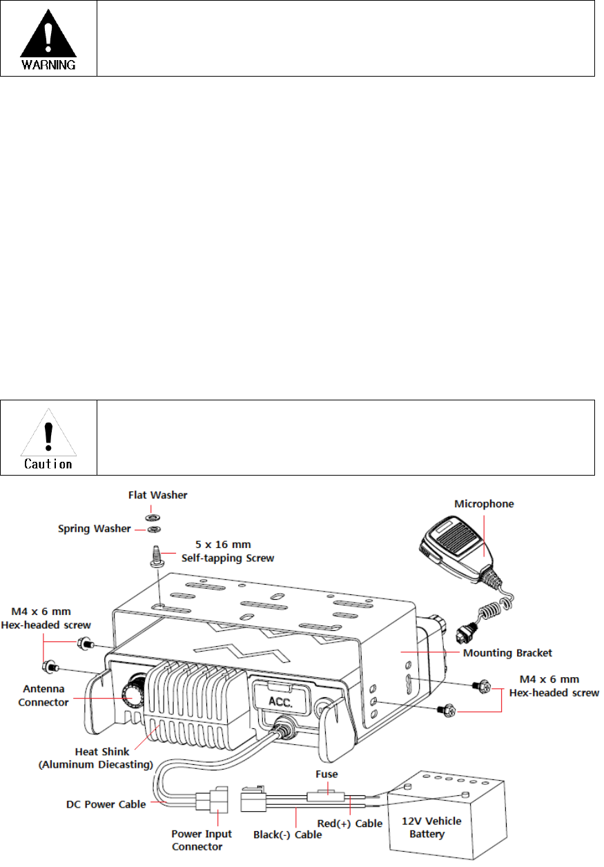
Installing the transceiver
For passenger safety, install the transceiver securely using the supplied
mounting bracket and screw set, so the transceiver will not break loose in the
event of a collision.
1. Mark the position of the hole in the dash, using the mounting bracket as a template.
Using a 4.2mm(5/32 inch) drill bit, drill the holes, then attach the mounting bracket
using the supplied screws.
• Mount the transceiver within easy reach of the user and where there is sufficient
space at the rear of the transceiver for cable connections.
2. Connect the antenna and the supplied power cable to the transceiver.
3. Slide the transceiver into the mounting bracket and secure it using the supplied hex-
headed screws.
4. Mount the microphone hanger in a location where it will be within easy reach of the
user.
• The microphone and microphone cable should be mounted in a place where they
will not interfere with the safe operation of the vehicle.
When replacing the fuse in the DC power cable, be sure to replace it with a
fuse of the same value. Never replace a fuse with one that is rated with a
higher value.
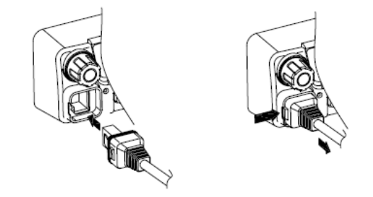
Connecting Microphone
1. Insert the microphone plug into jack on the front panel of the transceiver.
• Be sure the tab on the microphone plug is facing the left hand side.
2. Mount the microphone on the microphone hanger where it will be within easy reach of
the user
3. To remove the microphone plug, press the tab on the connector while pulling the plug
out of the transceiver jack
Figure 1-2) Installation and Removing the Microphone
Supplied Accessories
Carefully unpack the transceiver. We recommend the you identify the items listed below before
discarding the packing. If any item are missing or have been damaged during shipment, file a
claim the carrier immediately.
DC power cable
• 15A Fuse(XM-1000, XM-1200, XM-4000, XM-4200) -------------------- 1
Mounting Bracket -------------------------------------------------------------------- 1
Screw set
• 5 x 16 mm self-tapping screw ------------------------------------------- 4
• Hex-headed screw with washer ------------------------------------------- 4
• Spring washer ------------------------------------------------------- 4
• Flat washer ------------------------------------------------------- 4
Microphone(with cable)
• ACC 708 ------------------------------------------------------------------- 1
Microphone hanger(with 4 x16 mm self-tapping screws) ------------------- 1
Instruction manual ------------------------------------------------------------------- 1
2. Feature
The XM series Mobile Radio is developed to be user-friendly and compact design, to have
various features and to use at the Distribution / industrial / public areas for the safety &
convenience of users.
The followings are the main features of the XM Series Mobile Radio.
• 128 x 32 Dots Graphic LCD
• 512 Channels and 32 Groups are selectable.
• Channel spacing: 12.5KHz
• Wide Band Coverage (VHF : 136~174MHz, UHF : 400~470, 450~520MHz)
• Call guard squelch of standardized CTCSS / DCS
• Identification origination(2 Tone and 5 Tone)
• Built-in Scramble (Inversion Type)
• Built-in Compander (Compressor and Expander)
• GPS Data communication(Option)
• Normal scanning / Priority scanning
• BCL (Busy Channel Lock)/BCLO (Busy Channel Lock Out)
• 40W(UHF)/50W(VHF) Power Switchable
• Selectable Squelch Level (0~10)
• Time-Out Timer (TOT)
• Standard DTMF Encode and DTMF Decoder with ANI Function
• Programmable Home Channel Function
• Emergency & Built-in Emergency Microphone
• Talk Around
• Internal or External Speaker
• Remote Radio Stun / Revive (Use 5 tone)
• Ignition Function / Horn Alert / Public Address
• 4W Front-Mounted Speaker
• Heavy-Duty Microphone
• Various Parameters and PC downloading methods
• Built-in D-SUB15 Accessary Connector
• PC Program Tuning
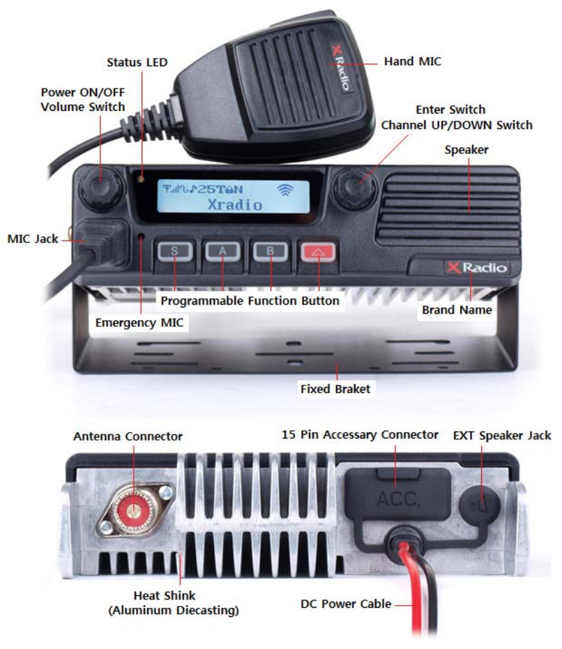
4. Appearance of XM Series Mobile Radio
Figure 4-1) Appearance XM-Series
Supplied Accessories
Item Part Number Quantity
ACC-810N : Programming Software(Narrow Band Only – United States Only)
ACC-820NW : Programming Software(Narrow and Wide Band – Outside the USA)
Acc-8025 : PC Programming Cable(USB)
ACC-708 : Mobile Microphone
5. Controls & keys
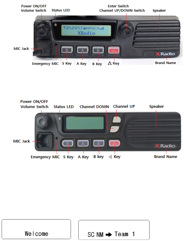
Figure 5-1) XM-1000 / XM-4000 Front panel
Figure 5-2) XM-1200 / XM-4200 Front panel
Power ON/OFF Volume switch
Press and hold the knob over 2 seconds to turn the mobile radio on and off.
Rotate to adjust the volume level from 1 to 16. Turn it clockwise to increases the volume
and counterclockwise to decreases the volume.
When the knob is pushed less 2 seconds, Squelch can be changed.
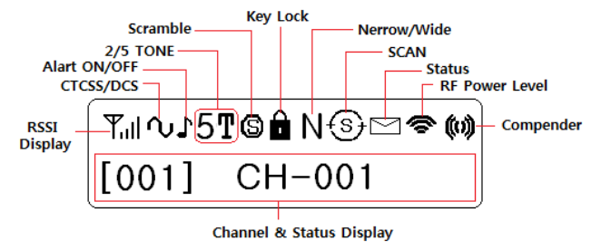
Display
It is a 125x 36 Graphic type. Each icon indicates related operation.
Figure 5-2) XM-Series LCD indicator
Selector
Rotate to select a channel. Clockwise increase the channel and counterclockwise decrease
the channel.
Press to select a group if the group is set.
Press and hold to enter a menu mode over 2 seconds.
Microphone Jack
Insert the microphone plug into this jack.
S Key
Press the key to activate its programmable function. The default setting is RF power /
Selcall.
A Key
Press the key to activate its programmable function. The default setting is Key tone/Menu.
B Key
Press the key to activate its programmable function. The default setting is TX inhibit/Scan.
△ Key
Press the key to activate its programmable function. The default setting is Monitor..
TX/Busy LED
The TX LED lights green while transmitting.
PTT switch
To send the signal, press and hold the switch, and then speak into the microphone.
Release to receive.
4.1 Programmable key functions
Keys can be programmed with the functions listed below. The key can only be programmed
with functions, depending on your use intention. Each key has two functions to be
programmed, as long press and short press. Please contact your dealer for further details
on the functions.
Channel up Talk around on/off
Channel down Fast Channel Mode
Monitor on/off BCL on/off
Key lock on/off Scramble on/off
Scan Mode Compander on/off
Selcall mode TX inhibit on/off
TX power change Key Tone on/off
Emergency TX Alert on/off
DTMF on/off GPS on/off
Horn Alert on/off Menu
Public Address on/off
The function can be selected only when GPS is installed.
4.2 Basic operations
Power on/off
Press and hold the volume knob to turn the radio on.
If the radio is protected with password. “PASSWORD INPUT” will appear on the display
when the power is on. To unlock the radio, enter the correct password.
1. Choose a number by rotating the selector
2. Press the selector to input the number
3. Repeat steps 1 and 2 to enter the whole password.
If no key is pressed within 10 seconds, the radio will return to the password protect state.
4. Press the selector to complete the entry over 1 seconds.
Press and hold the volume for approximately 2 seconds to turn the radio off.
Volume adjustment
Rotate the volume knob clockwise to increase the volume and counterclockwise to
decrease the volume. Maximum increment is 16 levels.
Channel selection / Group selection
Choose the wanted channel/group using the selector if it is programmed with group.
To select a group, push the selector and move to the wanted group. And then push the
selector at the wanted group as setting.
Transmitting
1. Choose the wanted group and a channel.
2. Press and hold the PTT switch, then speak into the microphone.
For best sound quality at the receiving radio, hold the microphone approximately 5~10cm
from your mouth.
3. Release the PTT to receive.
4. When you communication is completed, return the microphone to its hanger.
Receiving
1. Select the wanted group and channel
2. When a call is received, LED becomes green and re-adjust the volume as necessary.
The user should not press the PTT during the reception.
If 2/5 tones are programmed as close mode, without any matched tones, the radio doesn’t
work normally. As it were, sending and receiving signals are prohibited until the matched
tone is received.
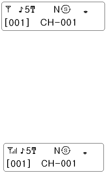
Scan
To activate the Scan function, press the “B” key( at default setting ) or the key programmed
as Scan over 2 seconds.
The “ “ icon and “ “ icon between Channel No. and Frequency appears on the display.
To stop the Scan, press and hold the “B” key ( at default setting ) over 2 seconds or push
the scan programmed key.
Normal scan
The scan is processed in the sequence of channels to be programmed. While the signal is
being received, if you want to return the scan without listening the call, press the “S” button.
If you delete the channel of receiving signal in the scan list during the receiving signal,
press the button “A”.
Priority scan
The priority scan is shown as “P-“ on the LCD. The priority scan is to check a receiving
status between each scan channels as the procedure like P, S1, P, S2, P, S3. The priority
channel is scanned periodically while the normal scan is checked. So, the priority is
received priory to other signals. During the status of receiving signal, the channel can be
moved to next scan channel by up/down button. Furthermore, the channel of receiving
signal can be deleted from the list of scan temporarily. When the priority is received, the
channel can not be changed or deleted.
Key lock
During call waiting, if the key programmed as key lock is pressed, the “ “ icon is shown on
the display. And the selector operation is halted and all keys except monitor function don’t
work.
4.3 Advanced operations
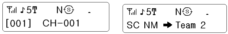
Selcall
*At programmed selcall, paging between individuals or groups can be available with 5 tones.
*Maximum 200 IDs’ can be memorized in the list.
*To escape sellcal model, press and hold the selector over 2 seconds.
No selcall operation Selcall operation
1) Call on selcall
ID selection
At call waiting, press the “S” key over 2 seconds at default setting or the key programmed as
selcall. Rotate the selector to select the selcall channel you want to call.
If you want to call “ID: A” in the list, select “A” by the selector.
And then push the selector to send the selcall signal to the radio you want to call.
If the program is set as sending caller’s ID altogether, the receiving radio is shown the caller’s
ID on the display.
Communication on the selcall
At selcall working, to select the channel of the party you want to talk.
Push the PTT button, and then caller’s ID is transmitted preferentially.
Emergency
When one of buttons is programmed as emergency, the emergency function can be activated.
When a button programmed as emergency is pressed over 2 seconds, the alert signal is
repeatedly transmitted in normal mode. When a radio is in 5 tone setting mode, the alert is
transmitted with 5 tones.
Fast Channel
Press a button programmed as Fast channel.
Rotate the selector to change channels.
Only channels programmed as Fast channel with ICON “F” is shown in the display.
This function is activated when some channels in the channel list are selected as Fast channel
by programmer and a button is pre-programmed as fast channel setting.
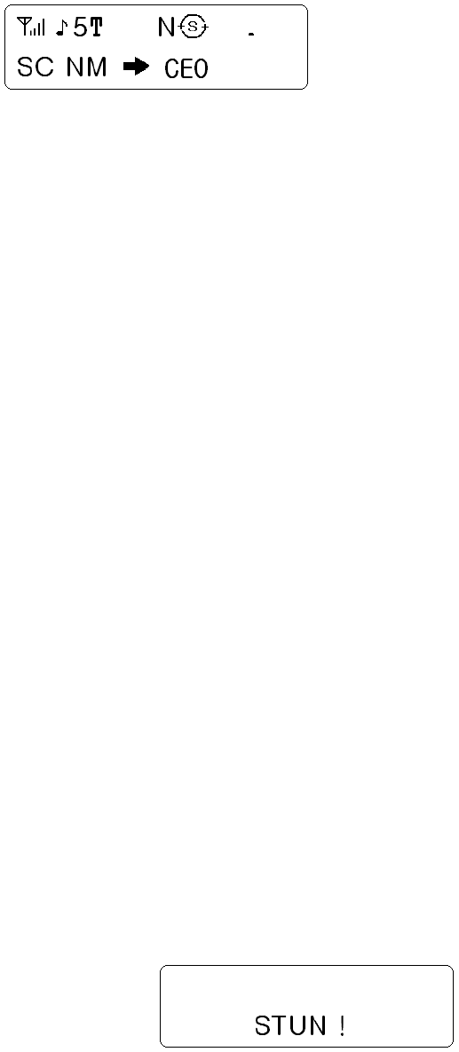
Stun/Revive
Stun status
When Stun/Revive function is programmed with selcal ID, stunning a radio or reviving a radio
can be activated by remote control.
When a radio programmed with Stun ID receives Stun ID from a control radio, all buttons of the
programmed radio is locked and out of control. At this status, only PTT works for sending alert
sounds. The matter what the power is reset, the stun status is continued until it receives Revive
ID.
Scramble/Descramble
This function is used for preventing eavesdropping.
BCL/BCLO
This function is to limit sending signals to avoid interrupting others’ communication when many
radio users are at same channel.
When the PTT is pushed, alert sounds with message shown on the display.
TOT
This function is to prohibit a radio from occupying one channel for a long time.
The alert sounds when the time programmed as sending signal is over.
If the penalty time is programmed, the signal can be sent after the time passes.
2 Tone
When 2 tone is matched between caller and receiver in the status of programmed 2 tone,
normal communication is performed.
Horn Alert
This function is to alert people away from vehicle through external speaker when certain calls
are received.
Public Address
This function is to route sounds from microphone to an external speaker or similar external
equipment.
Talk Around
When communication through repeaters is performed, this function is to allow communication
among radios directly if a repeater is out of range or out of order.
5. Menu Description
To enter into the menu, press and hold the right knob for 2 seconds. The menu is consisted of
10 main menus and total 29 sub-menus. So, if the menu is set according to circumstance and
purpose of use, the radio can be utilized conveniently. The main menu has the list such as
SCAN, ID ANI, Message, Pro. Message, Utility, Vehicle, Sound/Tone, RPT/Talk Ad, GPS,
Software Ver.. And it is selected by the rotation of right knob. And execute it by pushing the knob.
Main menu procedure
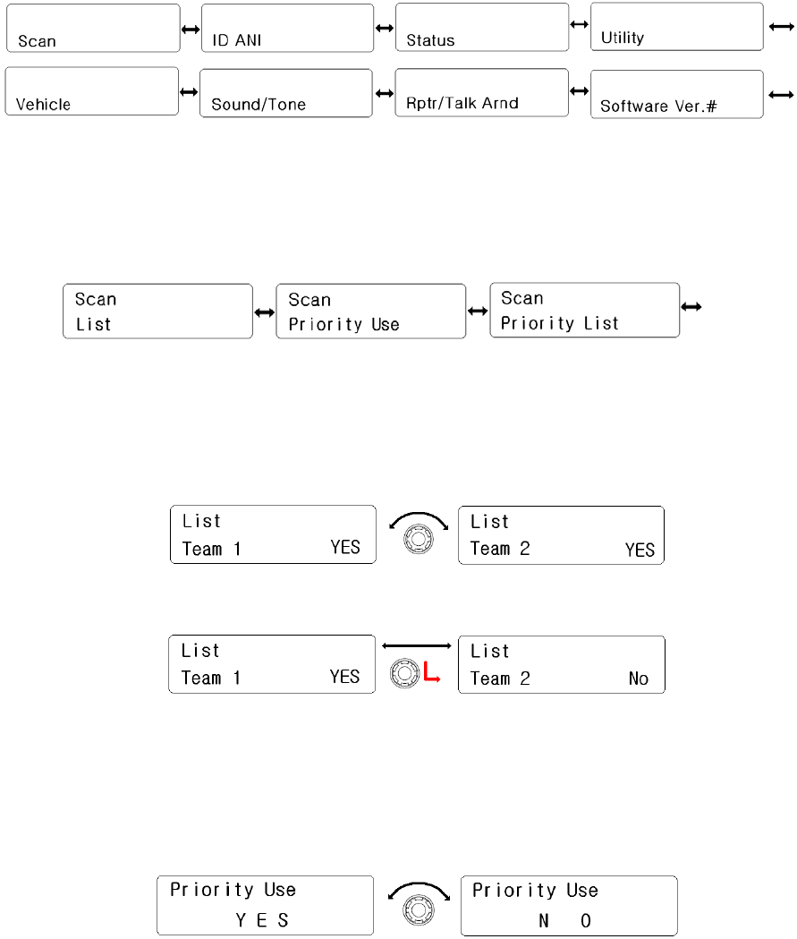
5.1 SCAN setting
It has 3 sub-menus (List, Priority Use, Priority List). The selection is performed by rotating
the right knob and the activation is by pushing the knob.
Scan sub-menu procedure
1) List
① The channel list of group and whether the channel is in the scan or not are
displayed as Yes or No. To move among channels, rotate the right knob.
② Press the right knob to select Yes or No.
③ To go to upper rank, press the red button.
2) Priority Use
① Rotate the right knob(Encoder) to change Yes/No.
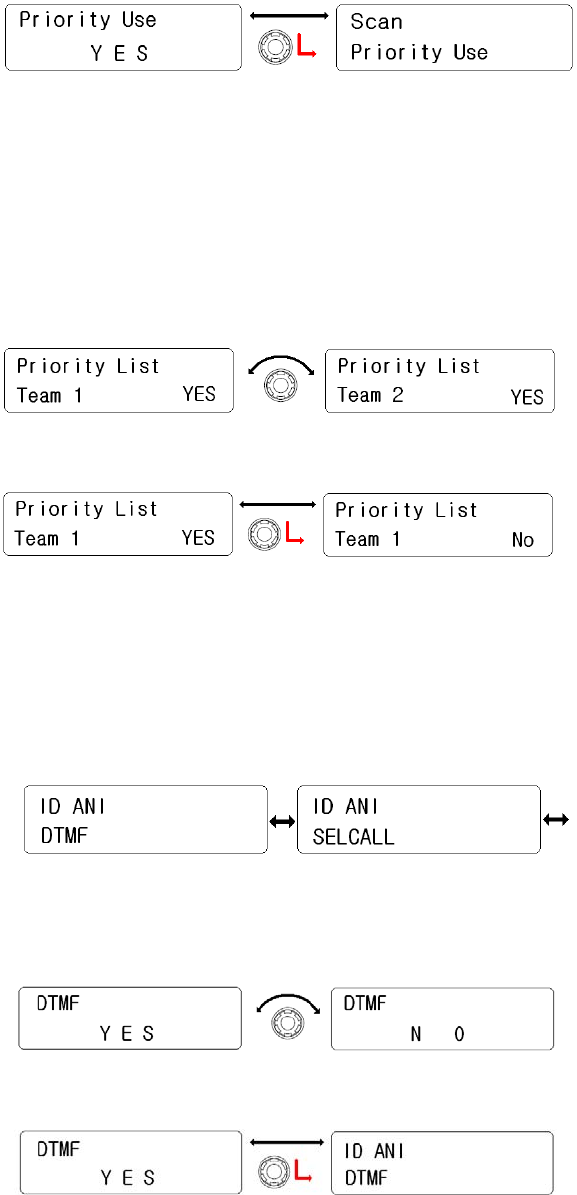
② Push the right knob(Encoder) to set, Back to upper menu.
③ To go to upper menu, press the Red button.
3) Priority List
① The channel list in the group and whether the channel is set as priority or
not are displayed as the sign of Yes or No. To change channel in the list,
rotate the right knob.
② Rotate the right knob(Encoder) to change Yes/No.
③ To go to upper menu, press the Red button.
5.2 ID ANI setting
It has two kinds of sub-menu as DTMF & Selcall. With the right knob, select one of them.
And set it by pushing the knob.
1) DTMF
① Rotate the right knob( Encoder) to select Yes or No.
② Press the knob to set, back to upper rank.
③ To move back to upper menu, press the red button.
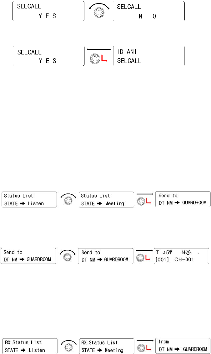
2) SELCALL
① Rotate the right knob(Encoder) to select Yes or No.
② Press the knob to set, back to upper rank.
③ To move back to upper menu, press the red button.
5.3 Status setting
It is consisted of two kinds like “Send” or “Receive Check”. Pre-programmed Status is sent
to the ID to be wanted receiving. And the receiving message can be checked. (Refer to
menu table)
1) Send
① Display pre-programmed Status. Rotate the right knob(Encoder) to
select a status to be sent, press the right knob(Encoder) to set.
② Rotate the right knob(Encoder) to select the ID which you wanted to
send the status. And then press the right knob(encode) to set.
③ After Automatically getting out of the menu, the radio send the status,
a receiver’s ID and a sender’s ID orderly.
2) Receive Check
① Rotate the right knob to select the received status for reading. And
then press the right know to check the sender’s ID.
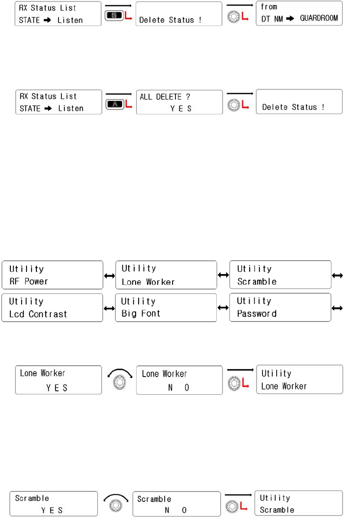
② To remove the received status, press the “S” button.
③ To erase all of the received status, press the “A” button and select
Yes .
5.4 Utility setting
There are six sub-menus (RF Power, Lone Worker, Scramble, Lcd Contrast, Big Font,
Password). Selection is done by the right knob(encoder) and press it to activate the
function.
1) Lone Worker
① Rotate the right knob(Encode) to select. And press it to set.
② To be back to upper menu, press the red button.
2) Scramble
① Rotate the right knob(Encode) to select. And press it to set.
② To be back to upper menu, press the red button.
3) Lcd Contrast
① Rotate the right knob(Encode) to select one of 20 steps. And
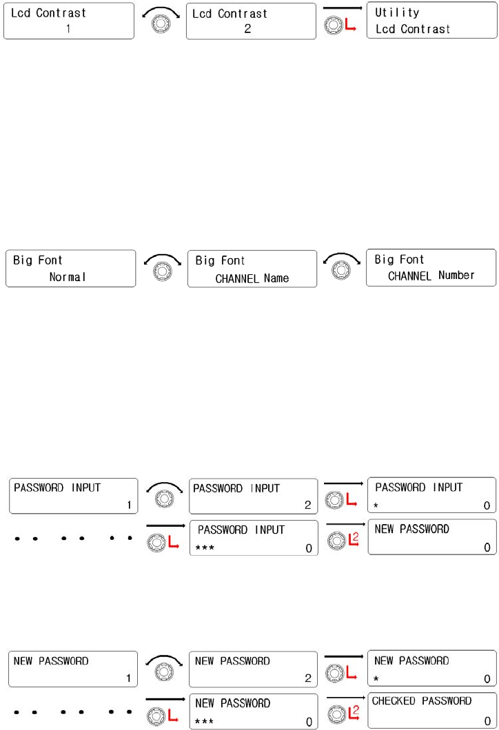
then press it to set
② To be back to upper menu, press the red button.
4) Big Fong
① Rotate the right knob(Encoder) to select one of them such as
“Name, Number, Normal”. And then press it to set.
② To be back to upper menu, press the red button.
5) Password
① When a Password is pre-programmed, ”PASSWORD INPUT” is
displayed on the LCD. And input the password. So, below No.2
step will be processed.
② When a password is not programmed, “NEW PASSWORD” is
shown on the LCD. So, input new password.
③ When “CHECKED PASSWORD” is shown, input new password
one again.
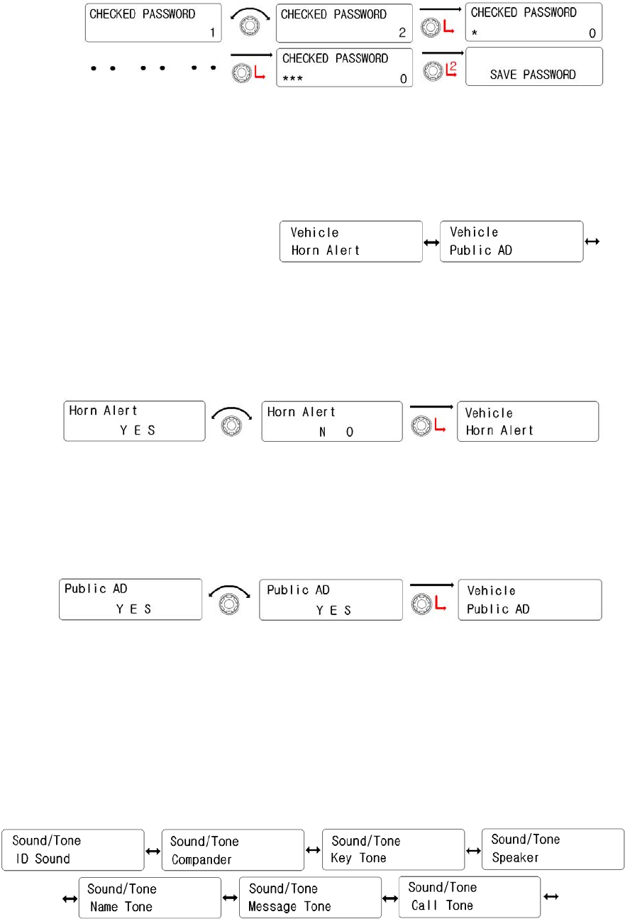
5.5 Vehicle setting
It has two kinds.(Horn Alert, Public AD). Rotate the right knob( Encoder ) to select one of
them. And then press the right knob to activate it.
1) Horn Alert
① Rotate the right knob( Encoder) to select “Yes”. And then press
the right knob(Encoder) to activate it.
② To be back to upper menu, press the red button.
2) Public AD
① Rotate the right knob( Encoder) to select “Yes”. And then press
the right knob(Encoder) to activate it.
② To be back to upper menu, press the red button.
5.6 Sound/Tone
There are 7 kinds of sub-menu. (ID Sound, Comapnder, Key Tone, Speaker, Name Tone,
MSG Tone, Call Tone) Selection is done by the right knob(Encoder). Activation is by
pressing the right knob.
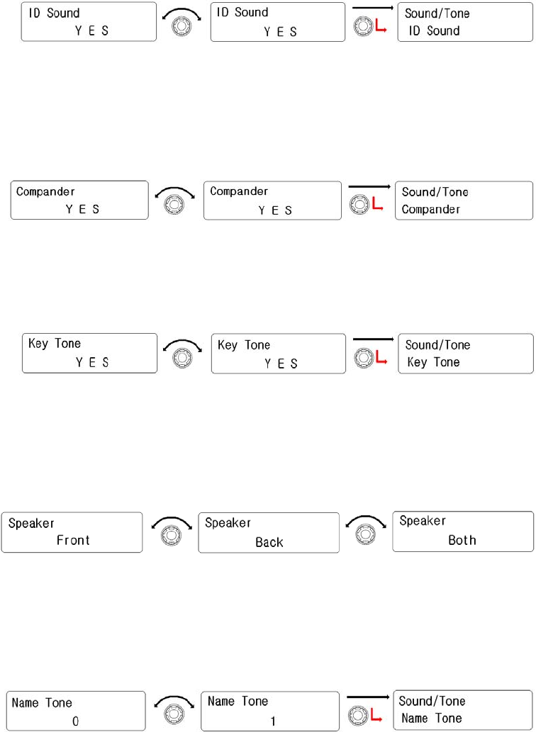
1) ID Sound
① Rotate the right knob( Encoder) to select “Yes”. And then press
the right knob(Encoder) to activate it.
② To be back to upper menu, press the red button.
2) Compander
① Rotate the right knob( Encoder) to select “Yes”. And then press
the right knob(Encoder) to activate it.
② To be back to upper menu, press the red button.
3) Key Tone
① Rotate the right knob( Encoder) to select “Yes”. And then press
the right knob(Encoder) to activate it.
② To be back to upper menu, press the red button.
4) Speaker
① Rotate the right knob( Encoder) to select one of them(Front,
Back, Both). And then press the right knob(Encoder) to activate
it.
② To be back to upper menu, press the red button.
5) Name Tone
① Rotate the right knob(Encoder) to select preferred tone. And
then press it to set.
② To be back to upper menu, press the red button.
6) Message Tone
① Rotate the right knob(Encoder) to select preferred tone. And
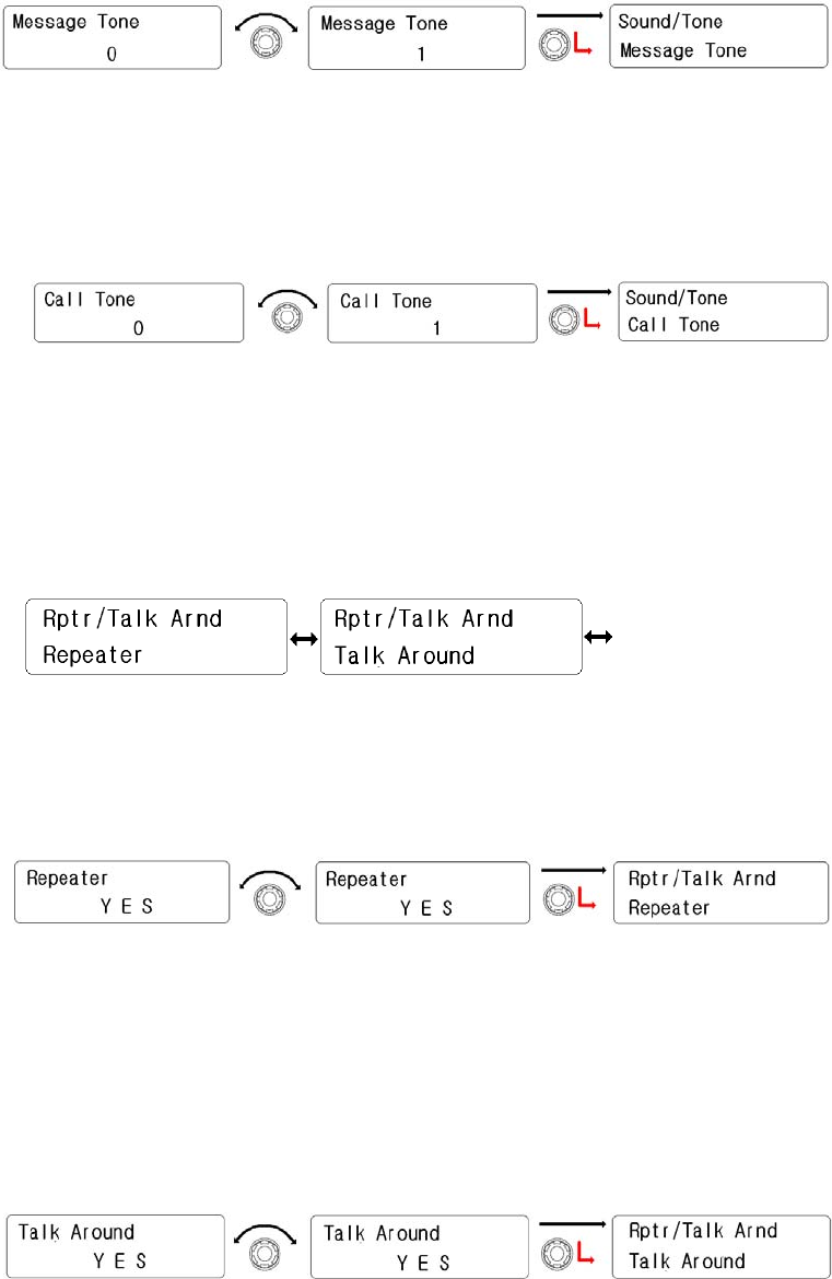
then press it to set.
② To be back to upper menu, press the red button.
7) Call Tone
① Rotate the right knob(Encoder) to select preferred tone. And
then press it to set.
② To be back to upper menu, press the red button.
5.7 Repeater/Talk Around
It is consisted of 2 kinds sub-menus.(Repeater, Talk Around). Selection is done by the right
knob(Encoder). Setting is by pressing the right knob.
1) Repeater
① Rotate the right knob( Encoder) to select “Yes”. And then press
the right knob(Encoder) to activate it.
② To be back to upper menu, press the red button.
2) Talk Around
① Rotate the right knob( Encoder) to select “Yes”. And then press
the right knob(Encoder) to activate it.
② To be back to upper menu, press the red button.
5.8 GPS setting
It is consisted of 4 kinds sub-menus.( Method, Interval, Sync Slots, Slot No). Selection is
done by the right knob(Encoder). Setting is by pressing the right knob.
To send your location data, you must first install a GPS unit onto the transceiver. Press the
key programmed as send the GPS data to transmit your location data. Ask your dealer for
details.
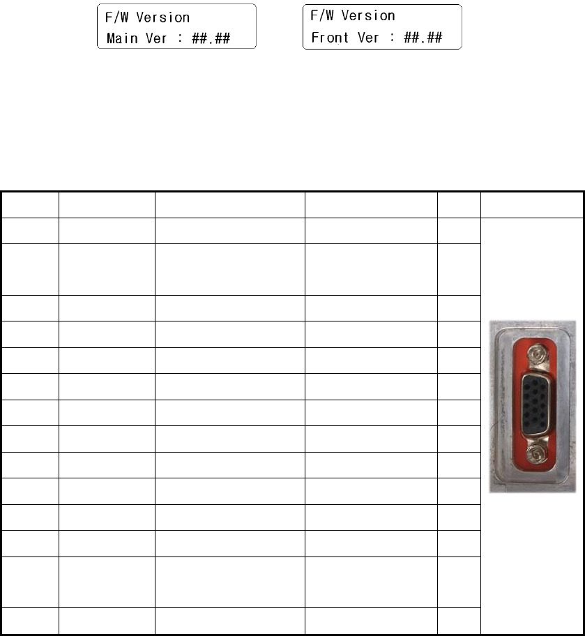
5.9 Software version
It shows the version of Front & Main’s firmware.
6. Terminal Description
ACC(D-SUB 15 Pin Connector)
Pin NO Pin Name Description Specification I/O Remake
1 DC+13.6V DC Power Output 13.8±15% O
2 IGN Ignition Signal Input Power ON : ↑ 8V
Power OFF : ↓ 6V
I
3 EXT_SPK Loudspeaker Output 4Ω, 4Watt O
4 AF_OUT Audio Output 500mV O
5 EXT_MIC Audio Input 5㏀ I
6 TXD/FCN1 TX Serial Data 3.3V TTL O
7 RXD/FCN2 RX Serial Data 3.3V TTL I
8 FCN3 Programmable High Impedance I/O
9 FCN4 Programmable High Impedance I/O
10 FCN5 Programmable High Impedance I/O
11 FCN6 Programmable High Impedance I/O
12 DC+5V DC Power Supply DC+5V Max 100mA O
13 HR1 Horn Alert Signal
Output
Max 3A O
14 HR2 Horn Alert Signal Max 3A O
Output
15 GND Ground Ground -
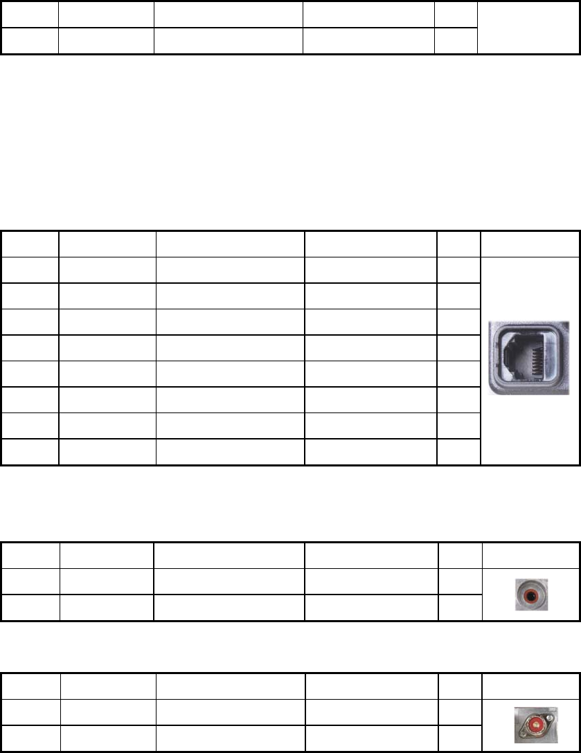
Microphone Jack
Pin NO Pin Name Description Specification I/O Remake
1 MBL Backlight of Microphone - O
2 DC+13.6V DC Power Output 13.8±15% O
3 GND Ground Ground -
4 PTT/TXD0 PTT/PC Serial Data 3.3V TTL I
5 ME MIC Ground MIC Ground -
6 MIC MIC Signal Input 600Ω I
7 HOOK/RXD0 HOOK/PC Serial Data 3.3V TTL I
8 DM MIC Data Detection High Impedance I/O
Speaker Jack(3.5mm Phone Jack) 4Watt/4Ω
Pin NO Pin Name Description Specification I/O Remake
1 SPO External Speaker Output 4Watt/4Ω O
2 GND Ground Ground O
DC Input Power Connector
Pin NO Pin Name Description Specification I/O Remake
Red DC+13.6V DC Power Output 13.8±15% I
Black GND Ground Ground I
Antenna Connector
Impedance is 50
7. Specification
7.1 XM-1000 / XM-4200
General
Frequency Range
Frequency Stability
Programmable Channels
Channel Spacing
Dimensions
Weight
Power Source
Current Drain (maximum)
VHF: 136 ~ 174 MHz
±1.5PPM (-30 to +60℃)
256 Channels/32 Group
Dual Channel Spacing 12.5 KHz
103mm (H)×52mm (W)×32mm (D)
1.1Kg
DC +13.8 ±15%
Receive mode, rated audio out – 1A (Audio Max)
Transmit mode – 11A
Standby mode – 300mA
Receiver
Sensitivity
Squelch Sensitivity
Selectivity
Spurious and Harmonic Rejection
FM Hum and Noise
Audio Output Power
Audio Distortion
Audio Response
IF Frequencies
Input Impedance
0.25uV 12 dB SINAD
0.22uV 10dB SINAD
70dB
75dB
40dB
4 Watt across an 8-ohm load
Less than 3% at rated output
+1, -3 dB from 6dB per octave de-emphasis Characteristic
from 300 ~ 3000Hz
21.4MHz and 455KHz
50 ohms
Transmitter
RF Power Output 50Watt
Spurious and Harmonic
FM Hum and Noise
Audio Distortion
Audio Frequency Response
Output Impedance
70dB
40dB
3% maximum with 1KHz modulation
+1, -3dB from 6dB per octave pre-emphasis Characteristic
from 300 ~ 3000Hz
50ohms
7.2 XM-4000 / XM-4200
General
Frequency Range
Frequency Stability
Programmable Channels
Channel Spacing
Dimensions
Weight
Power Source
Current Drain (maximum)
XM-4000A / XM-4200A : 400 ~ 475 MHz
XM-4000B / XM-4200B : 450 ~ 520 MHz
±1.5PPM (-30 to +60℃)
256 Channels/32 Group
Dual Channel Spacing 12.5KHz
103mm (H)×52mm (W)×32mm (D)
1.,1 Kg
DC +13.8 ±15%
Receive mode, rated audio out – 1A(Audio Max)
Transmit mode – 11A
Standby mode - 300mA
Receiver
Sensitivity
Squelch Sensitivity
Selectivity
Spurious and Harmonic Rejection
FM Hum and Noise
Audio Output Power
Audio Distortion
Audio Response
IF Frequencies
Input Impedance
0.25uV 12 dB SINAD
0.22uV 10dB SINAD
70dB
75dB
40dB
1 Watt across an 16-ohm load
Less than 3% at rated output
+1, -3 dB from 6dB per octave de-emphasis Characteristic
from 300 ~ 3000Hz
45.3MHz and 455KHz
50 ohms

Transmitter
RF Power Output
Spurious and Harmonic
FM Hum and Noise
Audio Distortion
Audio Frequency Response
Output Impedance
40Watt
70dB
40dB
3% maximum with 1KHz modulation
+1, -3dB from 6dB per octave pre-emphasis Characteristic
from 300 ~ 3000Hz
50 ohms