YEONHWA M TECH XR-2400 ZIGBEE UHF TRANSCEIVER User Manual XR 2400 Manual
YEONHWA M TECH CO.,LTD ZIGBEE UHF TRANSCEIVER XR 2400 Manual
Users Manual
1
XR-2400
User’s Manual
Zigbee UHF Transceiver
* This Service manual is subject to change according to improvement of XR-2400 Portable Radio
without notice.
* Version #1 (2011-08-14)

2
Table of Contents
1. XR-2400 Features -------------------------------------------- 3
2. Components of XR-2400 Series Radio ---------------------------------- 4
3. Appearance of XR-2400 Radio ----------------------------------------- 5
4. Basic Operation of XR-2400 ---------------------------------------------- 6
5. Operating XR-2400 Radio --------------------------------------------- 8
6. Operating Instructions of XR-2400 Radio --------------------------------- 11
7. FCC information --------------------------------- 12
3
1. XR-2400 Features
The features of XR-2400 are various as below. XR-2400 can used under tough industrial
environments as well as public places.
XR-2400 series have following functions:
16 Channels are selectable.
High-Quality Audio Output(Ø40 Speaker)
PLL synthesizer type
Signal Strength Meter
Battery Status Indicator
Advanced Speaker Protection technology
DC+3.7V 1,800mAH rechargeable Li-ion employment quantity battery use
4
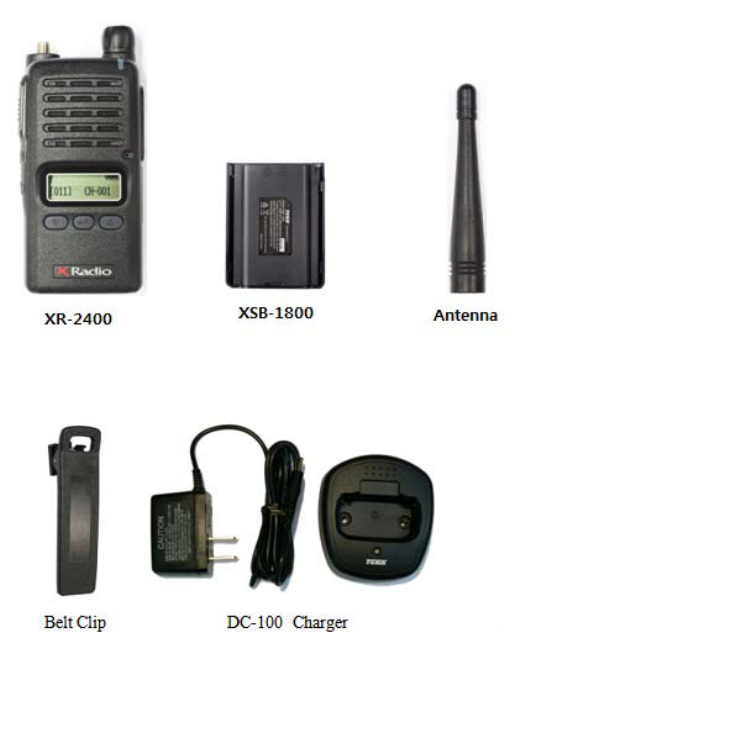
2. Components of XR-2400 Series Radio
* Components could be changed by buyer request.
Figure 2-1) standard components of XR-2400 Radio
5
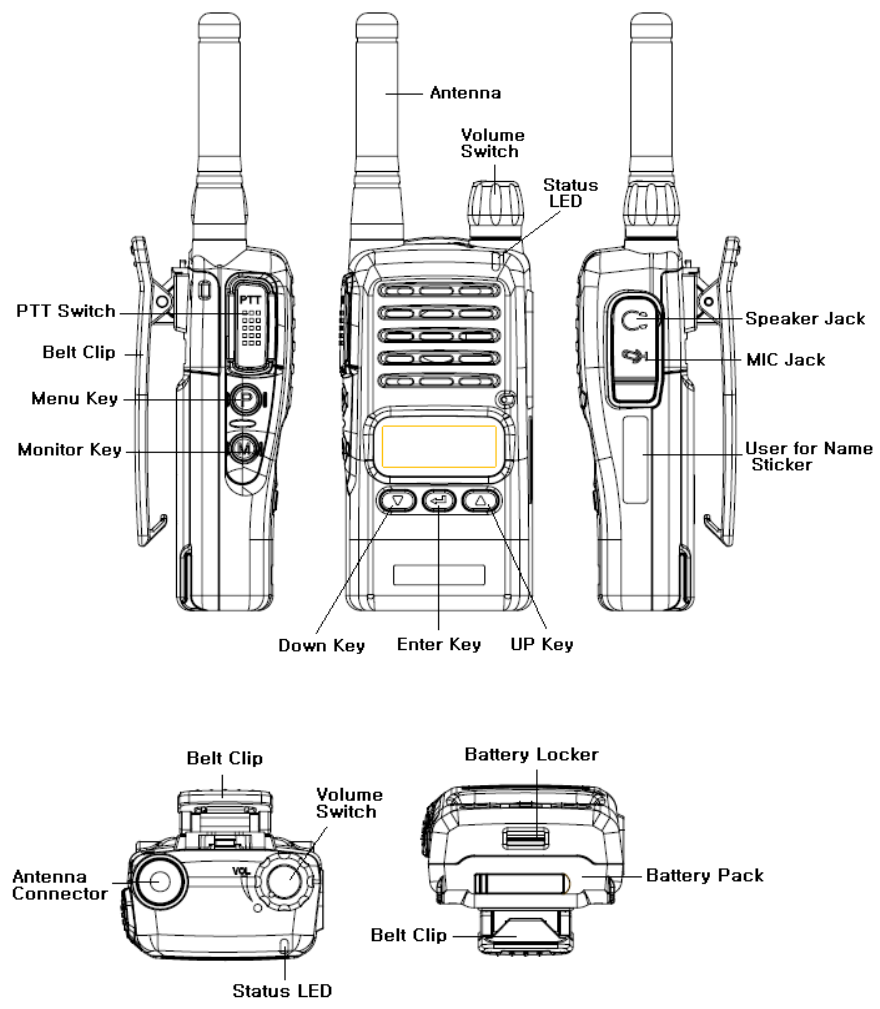
3. Appearance of XR-2400 Radio
Figure 3-1) Appearance of XR-2400 Radio
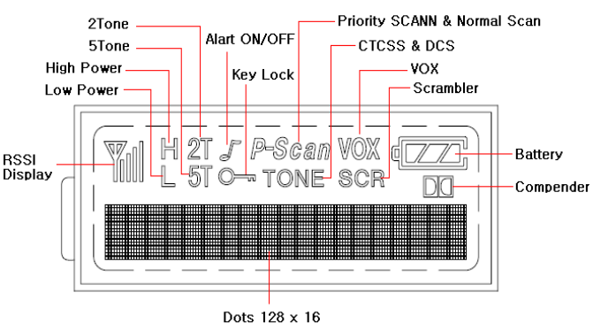
6
Figure 3-2) XR-2400 Series LCD Indication
4. Basic Operation of XR-2400
Pease read this manual carefully before using XR-2400 series Radio.
This manual contains important information about using Radio.
7
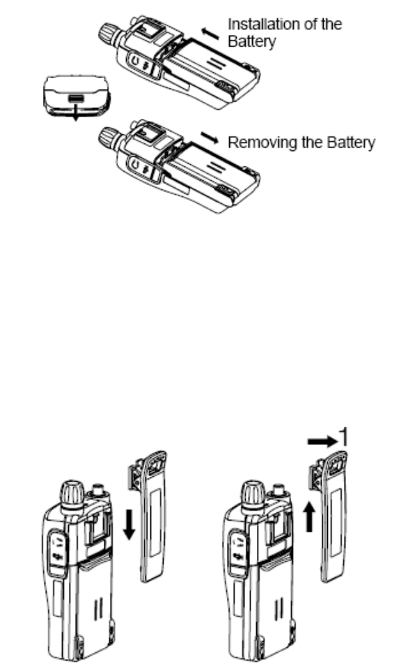
4.1 Installation and Removing the Battery
4.1.1 Installation of the battery
To install battery, slide up the battery towards the top of the radio until battery latch is locked.
4.1.2 Removing the Battery
- Slide the battery latch located on the bottom of radio to the open position as shown in
Figure 4-2.
- The battery is removed by pressing it against and sliding it towards the bottom of the radio
Figure 4-2) Installation and Removing the Battery
4.2 Installation and Removing the Belt Clip
- To attach belt clip to radio, align belt clip rails with the grooves in radio and slide the belt
clip onto the mounting rails until it latches into place.
- To remove belt clip from radio, push up on tab of belt clip with flat bladed screwdriver and
at the same time, slide the belt clip towards the top of Radio (Figure4-3).
Figure 4-3) Installation and Removing the Belt Clip
8
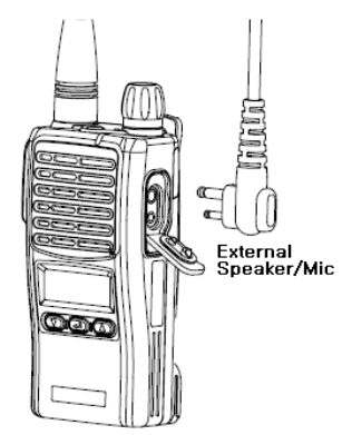
4.3 Accessory connector
Accessory connector is used to connect external speaker/Mic, and headset, etc.
Please close the cover when nothing is connected.
Figure 4-4) Accessory connector
5. Operating XR-2400 Radio
5.1 On/Off/Volume Control
Turns the radio on and off and adjusts audio volume level.
5.2 PTT Button(Push-To-Talk Button)
You can transmit by pressing PTT button. And then Red LED will be ON and your voice will be
transmitted.
5.3 Channel Buttons(▼,▲)
Channel Buttons(▼,▲) have 2 functions as shown in following.
① Channel buttons(▼,▲) are to change channels.
② Channel buttons(▼,▲) are to select menu at menu mode.
5.4 Accessory Connector
The Accessory Connector is used when using an external speaker microphone or doing PC
programming or making the Cloning or using as a Repeater.
9
5.5 RX /TX LED for Status
This LED is a lamp indicating the current status of the Radio and please refer to the below
contents.
① RX : Red Lamp
② TX : Green Lamp
③ CTCSS, DCS Error : Green Blinks.
④ Low Battery: Red Blinks With “beep” sound.
5.6. Charging the Battery
5.6.1 Safety Notes
1) The radio of XR-2400 series receives power from high-performance Li-ion battery (XSB-1800).
XSB-1800 Battery is safe of high performance and highly reliable, and could be charged very fast.
XSB-1800 Battery has been designed suitably only for the charger of DC-100.
The charging of the enclosed Radio on the other maker’s charger will
cause a damage on the battery and also, will cause a trouble on the
Radio.
2) Please charge the battery before using the radio for best performance and safety.
1) When you charge the battery that is installed in the Radio, please turn off the radio first to
charge the battery.
The continuous rapid discharge (for example, when making a short
circuit on the ‘+’ terminal of battery by a metal substance) may make a
fatal defect and the battery can be exploded. Also, it can cause a fire.
4) Using the correct battery will improve the efficiency and safety.
5.6.2 The Time of Charging
Low battery voltage will make the radio less coverage and also make the performance worse.
Please charge the battery in case of following:
① When you think performance of the radio becomes lower
② When the red lamp on RX/TX Led blinks (every 0.5 second) during transmission or
reception
③ When the battery icon blinks
4) When “beep” sound is generated while the radio is in use.
10
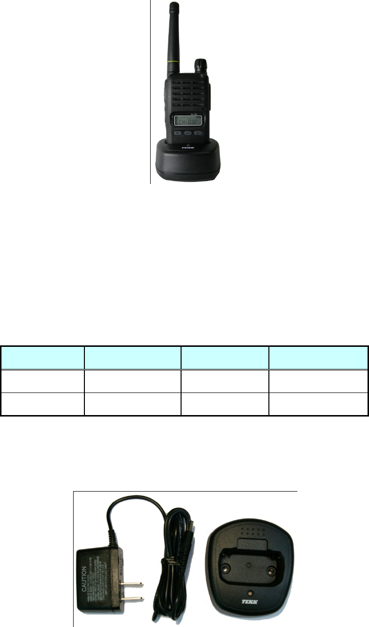
Figure 5-1) Charging the Battery
5.6.3 How to Charge
1) Plug the DC-100 charger into the electricity power outlet.
2) When charging the Radio with the battery installed, please turn off the power of the
Radio and place the Radio on the charger (The charger has a slide slot.).
3) After completion of the charging, the green LED on the charger will light. However,
please continue the charging for 30 more minutes for the complete full charge.
status LED indication status LED indication
During charging Red LED lights. Detecting error Red LED is off.
After charging Green LED lights. When charging Green LED lights
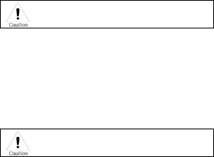
5.6.4 Charger (DC-100)
The DC-100 charger is designed to charge only the Li-ion battery enclosed in this Radio.
Figure 5-2) DC-100 Charger
11
Specifications of DC-100 Charger :
• Adaptor Input Voltage : AC 100 ~ 240V
• Adaptor Output Voltage : DC 5V
• Battery : XSB-1800
• Quick Changing Tume : In3Hours and half
• Operation Temperature : 0℃~+50℃
• Size : 76(W)x85(D)x37(H)m/m
• Charging Current : 750mA(Fast charging)
6. Operating Instructions of XR-2400 Radio
6.1 Power On/Off
Turn Power switch clockwise. As soon as power is supplied, the backlight will be turned on.
If the user had set up the user ID, it will be displayed on the LCD and radio will enter into the
latest state as a signal sound is generated.
When turning (power) on the radio by pressing a button on it, the radio
may enter into a special modes in which transmission and reception is
impossible. Please don’t turn on the radio by above way.
6.2 Transmission Method
For transmission, press PTT button on the left side of the radio. As soon as the user presses
keys according to the setting, DTMF ID will be transmitted, and during this time, voice
communication will be interrupted for several seconds. Then, red LEDs for transmission and
reception will be turned on. It is recommended to talk 5 ~ 10cm away from the microphone
for the best voice communication.
.
☞ Note: If the user makes transmission for more than a certain time while BCLO or TOT
feature is on, transmission will be forcefully disconnected for other users.
If present channel is TX Inhibited by pc program, TX will not be worked.
(By PC Program, it could be set)
6.3 Reception Method
The user should not press PTT button during the reception. The user can adjust the volume by
Volume switch, and during reception, the green LED will be turned on. Depending on conditions
12
of the transmitting radio,
6.4 Changing Channels
Channel buttons (▼,▲) are to change channels. Press Up button (▲). Then, “beep” sound will be
generated and the channel number will be increased. Or press Down button (▼) to decrease the
channel. If the user presses Up or Down button while only one channel is set, the channel will not
be changed and a different sound from “beep” will be generated. For fast increase or decease
channel numbers, press Channel buttons (▼,▲) for a while. In this case, however, “beep” sound
will not be generated.
7. FCC Information to User
This equipment has been tested and found to comply with the limits for a Class B digital device,
pursuant to Part 15 of the FCC Rules. These limits are designed to provide reasonable protection
against harmful interference in a residential installation. This equipment generates, uses and can
radiate radio frequency energy and, if not installed and used in accordance with the instructions,
may cause harmful interference to radio communications. However, there is no guarantee that
interference will not occur in a particular installation. If this equipment does cause harmful
interference to radio or television reception, which can be determined by turning the equipment
off and on, the user is encouraged to try to correct the interference by one of the following
measures:
• Reorient or relocate the receiving antenna.
• Increase the separation between the equipment and receiver.
• Connect the equipment into an outlet on a circuit different from that to which the receiver is
con-nected.
• Consult the dealer or an experienced radio/TV technician for help.
Caution
Modifications not expressly approved by the party responsible for compliance could void the
user’s authority to operate the equipment.
8. Safety Notes
Body-worn Operation
This device has been tested for body-worn operation and meets FCC RF exposure guidelines.
Body-worn operation is restricted to accessories that maintain a minimum of 1.5cm separation to
the body and do not contain metallic components. Use of any other body-worn accessories may
not compliance with FCC RF exposure guidelines.
13
9. WARNING
This transceiver generates RF EME while transmitting. RF EME(Radio Frequency Electric &
Magnetic Energy)has the potential to cause slight thermal, or heating effects to any part of your
body less than the recommended distance from this radio transmitter's antenna. RF energy
exposure is determined primarily by the distance to and the power of the transmitting device. In
general, RF exposure is minimized when the lowest possible power is used or transmission time is
kept to the minimum required for consistent communications, and the greatest distance possible
from the antenna to the body is maintain. The transceiver has been designed for and is classified
for Occupational use only. Occupational/controlled exposure limits are applicable to situations in
which persons are exposed to RF energy as a consequence of their employment, and such
persons have been made aware of the potential for exposure and can exercise control over their
exposure. This means you can use the transceiver only if you are aware of the hazards of
operating a transceiver and are familiar in ways to minimize these hazards. This transceiver is not
intended for use by the general public in uncontrolled environments. Uncontrolled environment
exposure limits are applicable to situations in which the general public may be exposed to RF
energy ,or in which the persons who are exposed as a consequence of their employment may not
be fully aware of the potential for exposure or cannot exercise control over their exposure
The following list provides you with the information required to ensure that you are aware of RF
exposure and of how to operate this transceiver so that the FCC RF exposure limitations are not
exceeded.
> While transmitting(holding the PTT switch), always keep the antenna at least 2.5cm (1 inches)
from your body or face ,as well as from any bystanders
> Do not transmit for more than 50% of the total transceiver use time; transmitting over 50% of
the total use time may exceed the limits in accordance to the FCC RF exposure requirements.
Nominal transceiver operation is 5% transmission time,5% reception time, and 90% stand-by time
> Use only the specified antenna for this transceiver; this may be either the antenna provided
with the transceiver or another antenna authorized by Yeonwha M tech. Use only Yeonwha M
tech authorized accessories (antennas, battery packs, belt clips)