YEONHWA M TECH XU-100A FM TRANSCEIVER User Manual
YEONHWA M TECH CO.,LTD FM TRANSCEIVER
User Manual
SERVICE MANUAL
VHF Transceiver
XV-100A
UHF Transceiver
XU-100A
* This Service manual is subject to change according to improvement of
2
==== CONTENTS ====
1.
3
1. XV-100A / XU-100A Features
The features of
4
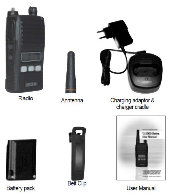
2. Components of XV-100A / XU-100A Radio
* Components could be changed by buyer request.
Figure 2-1) standard components of
5
TJA-30NC Case - Nylon w/Belt Loop/Swivel
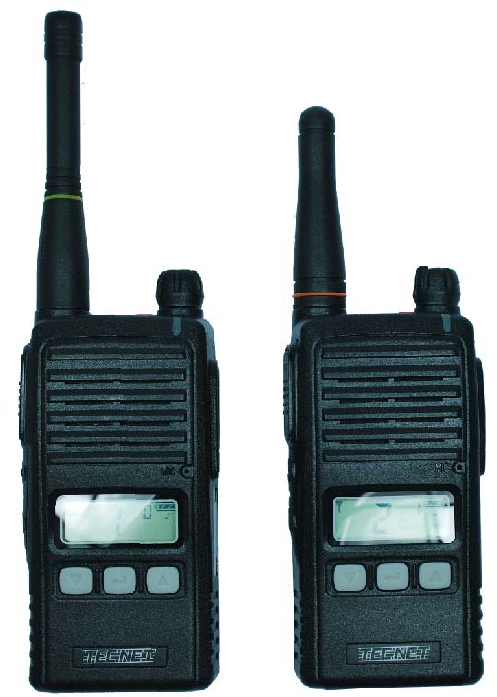
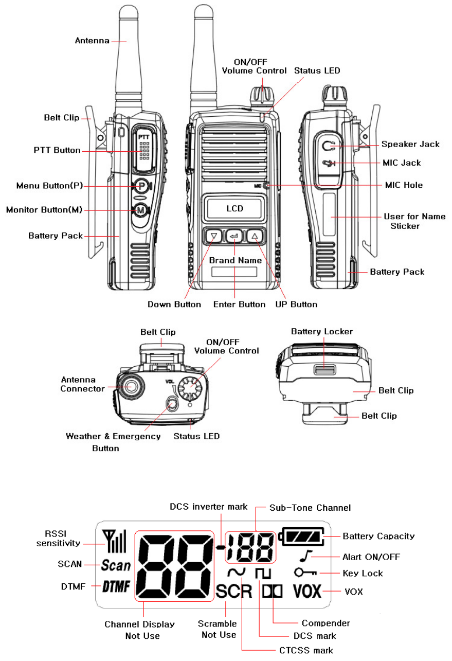
3. Appearance of XV-100A / XU-100A Radio
Figure 3-1) Appearance of XV-100A / XU-100A Radio
6
Figure 3-2)
7
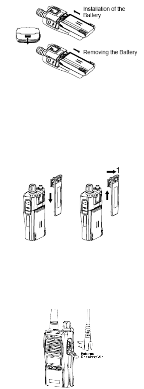
Figure 4-2) Installation and Removing the Battery
4.3 Installation and Removing the Belt Clip
- To attach belt clip to radio, align belt clip rails with the grooves in radio and slide the belt clip
onto the mounting rails until it latches into place.
- To remove belt clip from radio, push up on tab of belt clip with flat bladed screwdriver and at
the same time, slide the belt clip towards the top of Radio (Figure4-3).
Figure 4-3) Installation and Removing the Belt Clip
4.4 Accessory connector
Accessory connector is used to connect external speaker/Mic, and headset, etc.
Please close the cover when nothing is connected.
Figure 4-4) Accessory connector
8
5. Charging the Battery
5.1 Safety Notes
1) The radio of
9
status LED indication status LED indication
During charging Red LED lights. Detecting error Red LED is off.
After charging Green LED lights. When charging Green LED lights
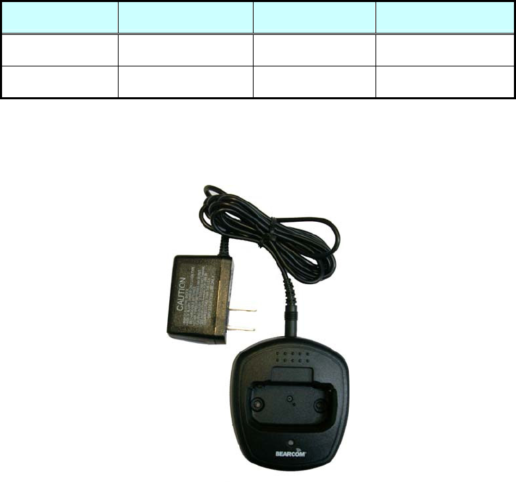
5.4 Charger (TJA-300L)
The TJA-300L charger is designed to charge only the Li-ion battery enclosed in this Radio.
Figure 5-2) TJA-300L Charger for TJ-3100V/3400U Radio
Specifications of TJA-300L Charger :
• Input Voltage : DC85 ~ 250V
• Battery : TJA-1800LI
• Quick Changing Time : In 4Hours and half
• Operation Temperature : 0℃~+50℃
• Size : 75(W)x84.5(D)x36(H)m/m
• Charging Current : 750mA(Fast charging)
10
6. Operating XV-100A / XU-100A RADIO
6.1 On/Off/Volume Control
Turn the knob of Volume Switch clockwise to turn the Radio on and if turning the Switch to the
opposite direction, the Radio is turned off. The audio volume level can be adjusted by turning the
Volume Switch and when adjusting the volume, please refer to the index mark indicated nearby the
Volume knob.
Turns the radio on and off and adjusts audio volume level.
6.2 PTT Button(Push-To-Talk Button)
If pressing the PTT button, the status indication LED lights in red color and the Radio is converted
to transmission mode. If releasing the PTT button, the Radio is converted to reception mode or
standby mode. It is recommended to talk about 5~7cm away from the microphone for using in
better sound quality and for better voice communication
6.3 Menu Button(P, Program Menu Button)
Enter into Menu mode by pressing the Menu button (P) for 2 seconds.
The sequence of menu mode is as follows.
6.4 Monitor Button(M)
The monitor mode is enabled and disabled by pressing the Monitor button (M) on the side.
Normal Mode : During pressing the (M) button for about 2 seconds, it is possible to check the
receiving status.
Continuous Mode : During pressing the (M) button for more than 2 seconds, the Radio will make a
“Beep” tone, which means the monitor function is maintained and if you press the (M) button again,
the monitor function will be released.
6.5 Emergency Button
In case of emergency situation, if you press the Emergency button, a siren sound will be heard
through the speaker in the Radio and the Radio will transmit the emergency signal to the party
through the emergency channel.
11
6.6 Channel Buttons(▼,▲)
Channel Buttons(▼,▲) have 3 functions as shown in following.
Channel buttons(▼,▲) are to change channels.
Channel buttons(▼,▲) are to select menu at menu mode.
Menu(p) + Channel up(▲) are to Channel Lock, Menu(p) + Channel down(▼) are to Channel
unlock
6.7 Accessory Connector
The Accessory Connector is used when using an external speaker microphone or doing PC
programming or making the Cloning or using as a Repeater.
6.8 LED Status
The LED indicates various status' of the radio.
(1) RX - Green color
(2) TX - Red color during PTT
(3) CTCSS, DCS Error - Green color blinking
(4) Low Battery - Red color blinking with beep tone
6.7 Function Operation
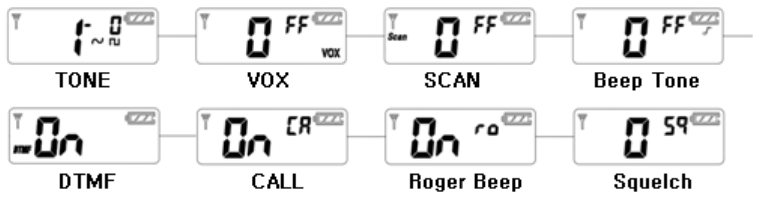
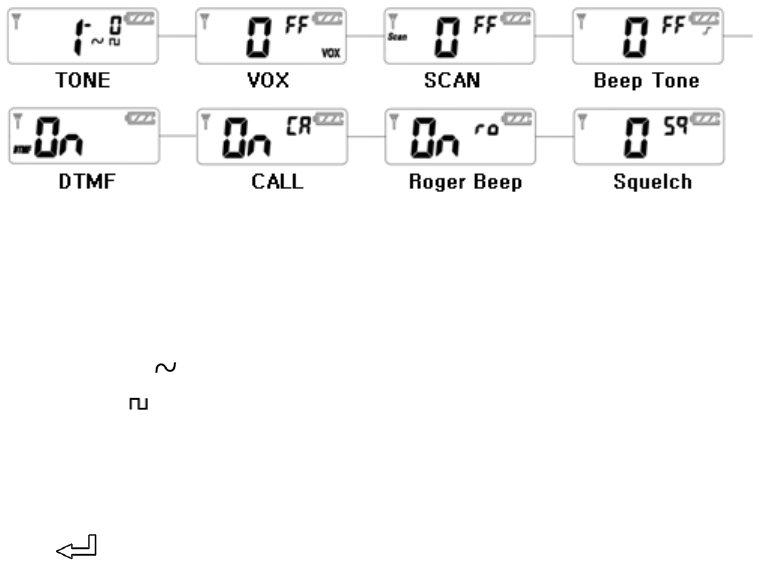
Enter into Menu mode by pressing the Menu button (P) for 2 seconds.
The sequence of menu mode is as follows.
6.8 CTCSS/DCS/DCS Inverter sub-tone channel selection:
Press Menu (P) button for more than 1 second and the radio will go into function setting mode.
Press UP (▲) or DOWN (▼) button to select Type of Sub-Channel.
CTCSS Sub-Channel : ( )
DCS Sub-Channel : ( )
DCS Inverter Sub-Channel : (▬)
No setting Sub-Channel : (0)
To select CTCSS tone sub-channel, select ( ) by pressing UP (▲ ) or DOWN (▼ ) button, and
press Enter ( ) button.
12
Sub-Tone channel LCD digit will be blinking
Press Up or DOWN to select your desired channel (1~38), and press Enter ( ) button to
confirm it.
To exit from menu, press M button or PTT switch.
Use same method to set up DCS ( ) or DCS Invertor ( ) Sub-Tone Channels
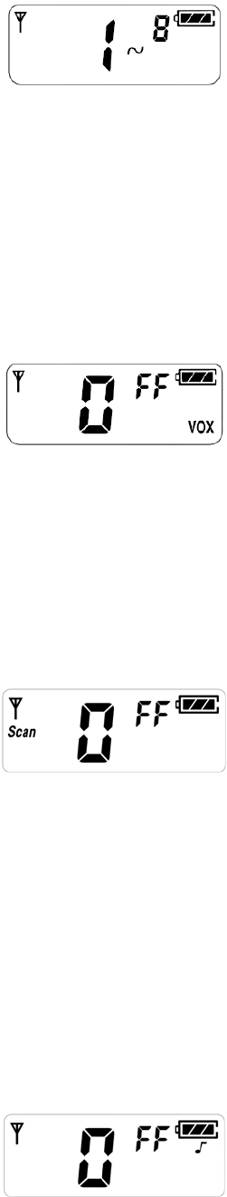
6.8.1 VOX Function On/Off selection:
Press Menu (P) button for more than 1 second and the radio will enter into function setting mode.
Press Menu (P) button again. Then VOX setting Icons will be blinking.
By pressing UP (▲) or DOWN (▼) button, you can select on or off. To exit from menu, press M
button or PTT switch.
6.8.2 Scan On/Off selection:
Press Menu (P) button for more than 1 second and the radio will enter into function setting mode.
Press Menu (P) button 2 times. Radio will go to Scan setting menu mode.
By pressing UP (▲) or DOWN (▼) button, you can select On or Off.
Select on and press Enter ( ) button to confirm Scan On. To exit from menu, Press M button or PTT
switch
If you want to enable Scan function, Press Menu (P) + Enter ( ) at the same time.
Then radio will begin scan. To stop Scan, press Menu (P) button.
( With programming software, a more selective type of scan method can be chosen.)
6.8.3 Beep Tone On/Off selection:
Press Menu (P) button for more than 1 second and the radio will enter into function setting mode.
Press Menu (P) button 3 times. Radio will go to Beep tone on/off setup mode.
13
By Pressing UP (▲) or DOWN (▼) button, set Beep tone on or off. To exit from menu, press M
button or PTT button.
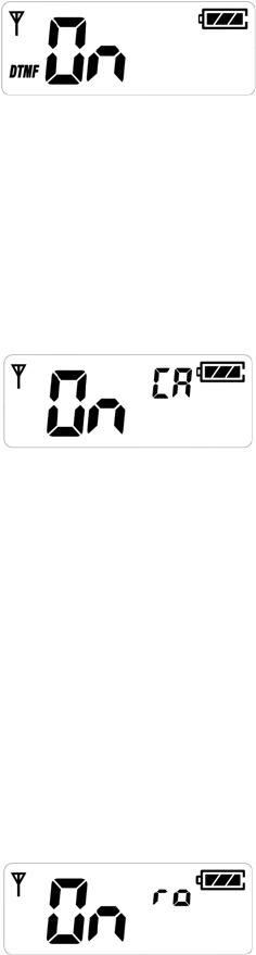
6.8.4 DTMF tone selection:
Press Menu (P) button for more than 1 second and the radio will enter into function setting mode.
Press Menu (P) button 4 times. Radio will go to DTMF setting mode. By pressing UP (▲) or DOWN
(▼) button, and pressing Enter( ) button, you can select 12 different DTMF tones.
To exit from menu, press M button or PTT button.
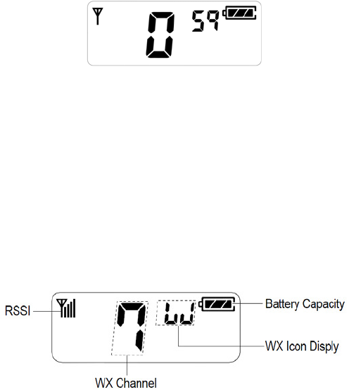
6.8.5 Call tone selection (10 different call tones):
Press Menu (P) button for more than 1 second and the radio will enter into function setting mode.
Press Menu (P) button 5 times. Radio will go to Call tone selection mode. By pressing UP (▲) or
DOWN (▼) button, and pressing Enter ( ) button, you can select On or Off.
If you select On and press Enter ( ) button, you can select 10 different Call tones by pressing
UP (▲) or DOWN (▼) button. To confirm your setting, please Enter (Icon) button. To exit from
menu, Press M button or PTT button. To enable Call, press Call/Enter( ) button.
Reminder : To receive Call tone, the receiving radio needs to be on the same channel and tone
settings.
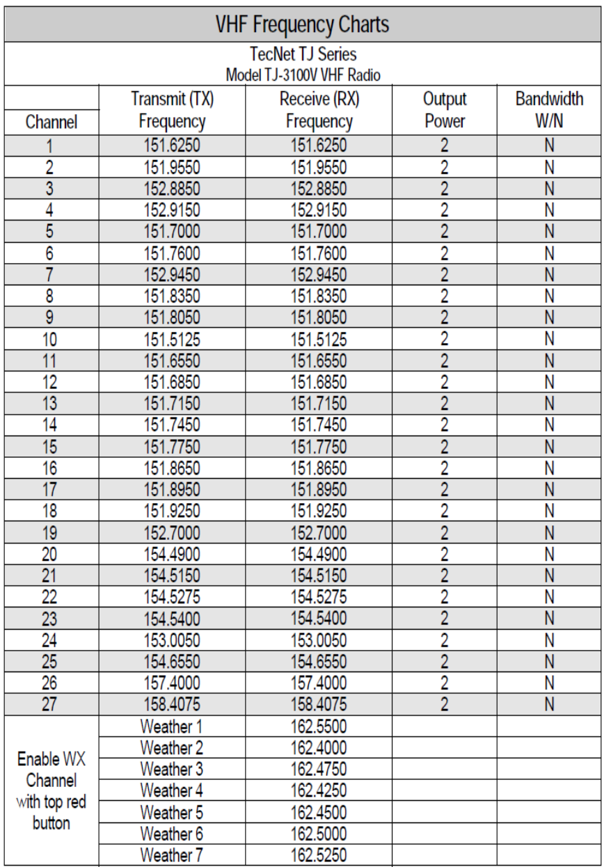
6.8.6 Roger Beep On/Off selection:
Press Menu (P) button for more than 1 second and the radio will enter into function setting mode.
Press Menu (P) button 6 times. Radio will go into Roger beep on/off setting mode.
By pressing UP (▲) or DOWN (▼) button will select on or off. To confirm your selection, press
Enter ( ) button.
To exit from menu, press M button or PTT switch.
6.8.7 Squelch level selection:
Press Menu (P) button for more than 1 second and the radio will enter into function setting mode.
Press Menu (P) button 7 times. Radio will goes into Squelch level selection mode.
14
By pressing UP (▲) or DOWN (▼), and Enter ( ) button, select your desired Squelch level from 0 to
4. ( 0 means the strongest level and 4 means the weakest level) To exit from menu, press M
button or PTT switch)
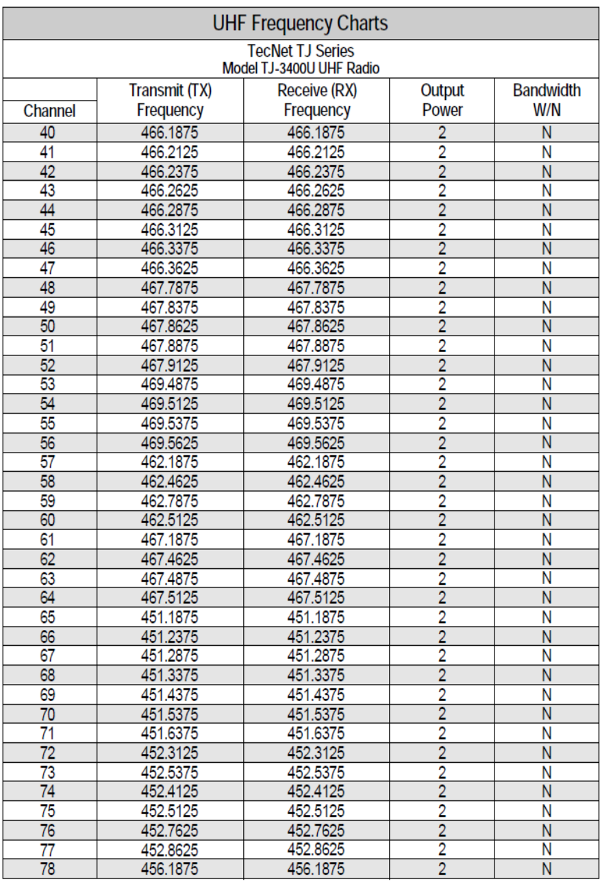
6.8.8 Weather On/Off selection:
To enable weather (WX) mode, do a quick press of red button on top of radio.
LCD will display WX mode. Press UP (▲) or DOWN (▼) button to move through WX channels.
To exit from WX mode, press red button again.
** Reminder : When WX mode is enabled, the radio will not transmit or receive talk
transmissions.
When WX is disabled, the radio will revert to it’s previous channel and mode of operation.
6.8.9 EMG (Emergency Alert Tone):
This function allows you to send out distress/locator signals in emergency situation. To activate the
emergency alert tone, press “Red Button” for more than 2 seconds.
The radio will send out a loud alert tone continuously. To deactivate the EMG function, press any
button on the radio.
** Reminder : To receive emergency alert tone, the receiving radio needs to be on the same
channel and tone settings.
15
7. Frequency Charts
7.1 VHF Frequency charts

16
7.2 UHF Frequency charts
17
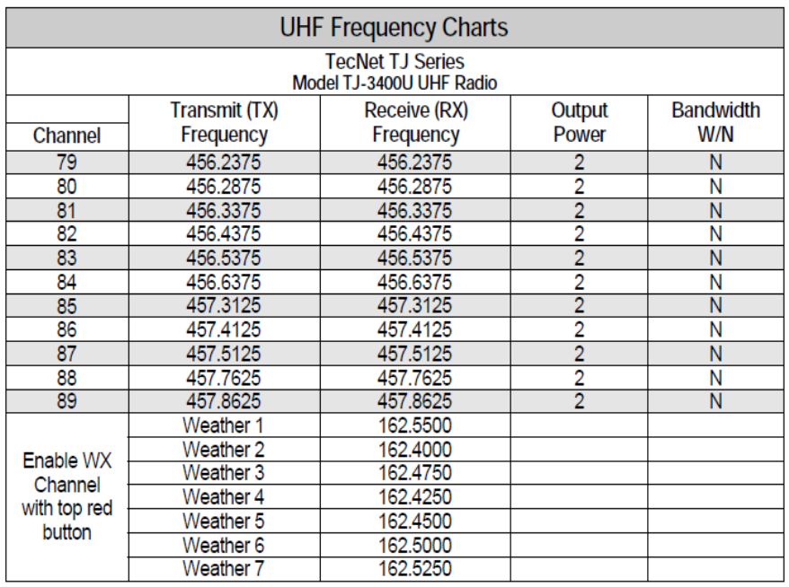
18
Note: Channels indicated for models other than
19
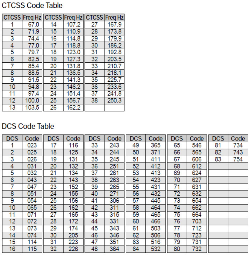
7.4 CTCSS and DCS Code Tables
20
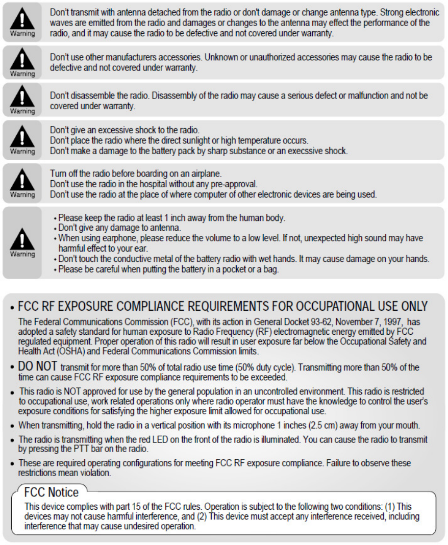
8. For Safe Operation
21
RADIO FREQUENCY ENERGY SAFETY INFORMATION
Your radio generates RF electromagnetic energy during transmit mode. This radio is designed
for and classified as “Occupational Use Only”, meaning it must be used only during the course of
employment by individuals aware of the hazards, and the ways to minimize such hazards. This
radio is NOT intended for use by the “General Population” in an uncontrolled environment.
This radio has been tested and complies with the FCC RF exposure limits for Occupational Use
Only. In addition, your XRADIO radio complies with the following Standards and Guidelines with
regard to RF energy and electromagnetic energy levels and evaluation of such levels for exposure
to humans:
■ FCC OET Bulletin 65 Edition 97-01 Supplement C, Evaluating Compliance with FCC Guidelines
for Human Exposure to Radio Frequency Electromagnetic Fields.
■ American National Standards Institute (C95.1-1992), IEEE Standard for Safety Levels with
Respect to Human Exposure to Radio Frequency Electromagnetic Fields, 3 kHz to 300 GHz.
■ American National Standards Institute (C95.3-1992), IEEE Recommended Practice for the
Measurement of Potentially Hazardous Electromagnetic Fields– RF and Microwave.
■ The following accessories are authorized for use with this product. Use of accessories other
than those (listed in the instruction) specified may result in RF exposure levels exceeding the FCC
requirements for wireless RF exposure. To ensure that your expose to RF electromagnetic energy
is within the FCC allowable limits for occupational use, always adhere to the following guidelines:
■ DO NOT operate the radio without a proper antenna attached, as this may damaged the radio
and may also cause you to exceed FCC RF exposure limits. A proper antenna is the antenna
supplied with this radio by the manufacturer or antenna specifically authorized by the manufacturer
for use with this radio.
■ DO NOT transmits for more than 50% of total radio use time (50%duty cycle). Transmitting
more than 50% of the time can cause FCC RF exposure compliance requirements to be exceeded.
The radio is transmitting when the TX indicator lights red. You can cause the radio to transmit by
pressing the PTT switch.
■ ALWAYS keep the antenna at least 4 cm away from the body when
transmitting and only use the Xradio belt-clip which is listed in instructions when attaching the radio
to your belt, etc., to ensure FCC RF exposure compliance requirements are not exceeded. To
provide the recipients of your transmission the best sound quality, hold the antenna at least 4 cm
from your mouth, and slightly off to one side. The information listed above provides the user
with the information needed to make him or her aware of RF exposure, and what to do to as-sure
that this radio operates with the FCC RF exposure limits of this radio. Electromagnetic
Interference/Compatibility During transmissions, your XRADIO radio generates RF energy that
can possibly cause interference with other devices or systems. To avoid such interference, turn off
the radio in areas where signs are posted to do so. DO NOT operate the transmitter in areas that
are sensitive to electromagnetic radiation such as hospitals, aircraft, and blasting sites.
22
Occupational/Controlled Use The radio transmitter is used in situations in which persons are
exposed as consequence of their employment provided those persons are fully aware of the
potential for exposure and can exercise control over their exposure. OPERATING NOTES
■ When transmitting with a mobile radio, hold the radio in a vertical position with its microphone
90 cm away from your mouth. Keep the antenna at least 4 cm from your head and body.
■ If you wear a mobile two-way radio on your body, ensure that the antenna is at least 4
centimeters From your body when transmitting. PRECAUTIONS WARNING! NEVER hold the
transceiver so that the antenna is very close to, or touching exposed parts of the body, especially
the face or eyes, while transmitting. The transceiver will perform best if the microphone is 90 cm
away from the lips and the transceiver is vertical. WARNING! NEVER operate the transceiver
with a headset or other audio accessories at high volume levels. CAUTION! NEVER short the
terminals of the battery pack. NEVER connect the transceiver to a power source other than the
Battery listed below Such a connection will ruin the transceiver. DO NOT push the PTT when not
actually desiring to transmit
AVOID using or placing the transceiver in direct sunlight or in areas with temperatures below –30°C
(–22°F) or above +60°C (+140°F). DO NOT modify the transceiver for any reason. MAKE SURE
the flexible antenna and battery pack are securely attached to the transceiver, and that the antenna
and battery pack are dry before attachment. Exposing the inside of the transceiver to water will
result in serious damage to the transceiver. BE CAREFUL! The series transceivers employ
waterproof construction, which corresponds to IPX7 of the international standard IEC 60529 (2001),
1 m depth for 30 minutes. However, once the transceiver has been dropped, waterproofing cannot
be guaranteed due to the fact that the transceiver may be cracked, or the waterproof seal damaged,
etc. The use of non-XRADIO battery packs/chargers may impair transceiver performance and
invalidate the warranty.
FCC Notice Cautions. Changes or Modifications not expressly approved by the party responsible
for compliance could void the user's authority to operate the equipment.
23
9. Specification
9.1 XV-100A Specification
General
Frequency Range
Frequency Stability
Programmable Channels
Channel Spacing
Dimensions
Weight
Power Source
Current Drain (maximum)
Duty Cycle(5/5/90)
VHF: 140 ~ 170 MHz
±2.5PPM (-30 to +60℃)
128 Channels/16 Group
Dual Channel Spacing 12.5 KHz
97.5mm (H)×49.5mm (W)×25.5mm (D)
150g (with Battery pack & Antenna)
DC +3.7V rechargeable Li-ion 1800㎃H battery pack
Receive mode, rated audio out - 280㎃ (Audio Max)
Transmit mode – 1,500mA
Standby mode – 50mA
15.5 Hours(High) / 21 Hours(Low)
Receiver
Sensitivity
Squelch Sensitivity
Selectivity
Spurious and Harmonic Rejection
Inter-modulation
FM Hum and Noise
Audio Output Power
Audio Distortion
Audio Response
Speaker Impedance
.282uV 12 dB SINAD
.25uV 10dB SINAD
60dB
70dB
60dB
40dB
1 Watt across an 8-ohm load
Less than 5% at rated output
+1, -3 dB from 6dB per octave de-emphasis Characteristic
from 300 ~ 3000Hz
8 ohms
Transmitter
RF Power Output
Spurious and Harmonic
FM Hum and Noise
Audio Distortion
Audio Frequency Response
Output Impedance
2Watt
60dB
40dB
5% maximum with 1KHz modulation
+1, -3dB from 6dB per octave pre-emphasis Characteristic
from 300 ~ 3000Hz
50 ohms