YEONHWA M TECH XV-100A FM TRANSCEIVER User Manual
YEONHWA M TECH CO.,LTD FM TRANSCEIVER Users Manual
Users Manual
SERVICE MANUAL
VHF Transceiver
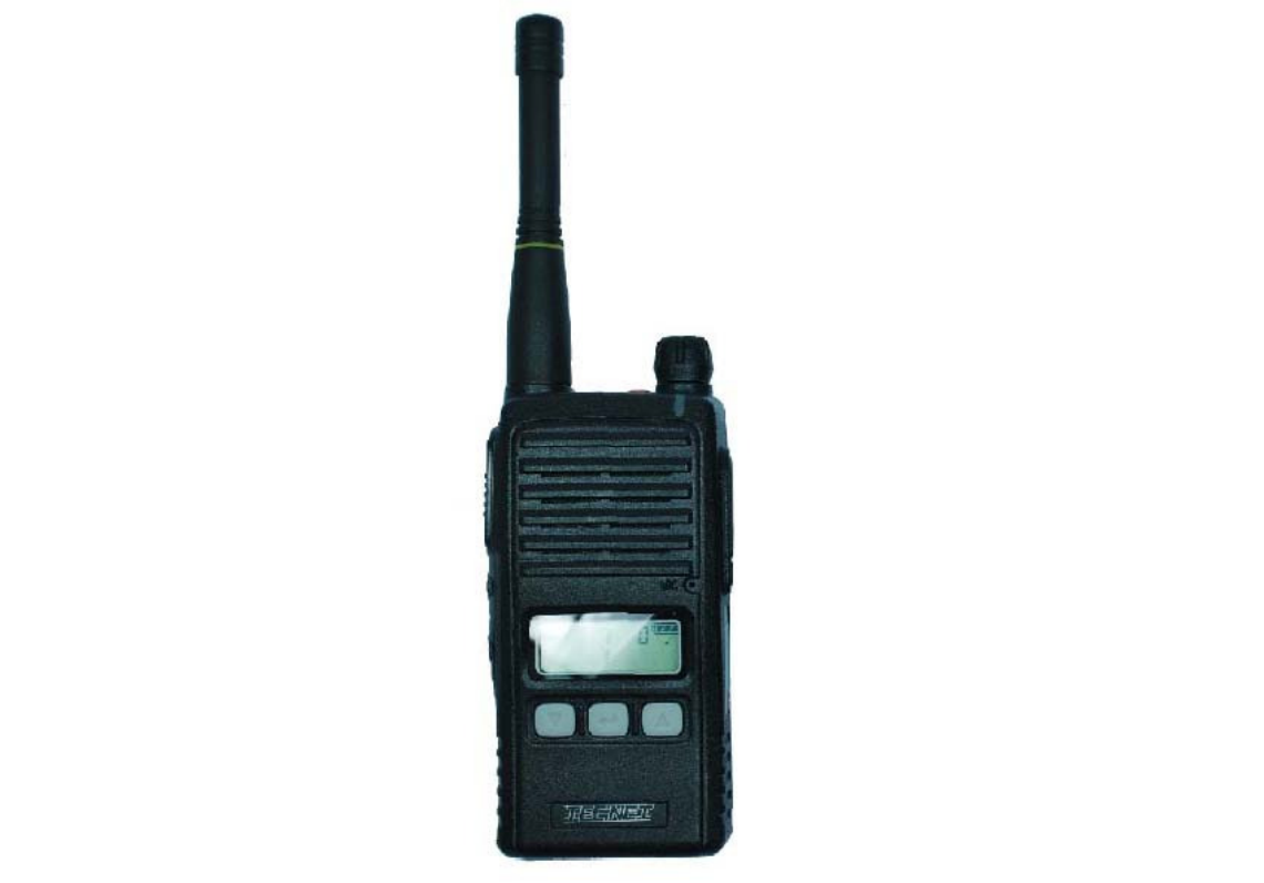
XV-100A
* This Service manual is subject to change according to improvement of XV-100A Portable
Radio without notice.
* Version #2 (2012-11-16)
2
==== CONTENTS ====
1. XV-100A Features ------------------------------------------------------- 3
2. Components of XV-100A Radio ------------------------------------------------------- 4
3. Appearance of XV-100A Radio ---------------------------------------------------- 5
4. Basic Operation of XV-100A ------------------------------------------------------ 7
5. Operating XV-100A RADIO ------------------------------------------------------- 8
6. Operating Instructions of XV-100A ----------------------------------------------- 10
7. Safety Notes ------------------------------------------------- 15
8. Specification ------------------------------------------------- 17
3
1. XV-100A Features
The features of XV-100A are various as below. XV-100A can used under tough
industrial environments as well as public places.
XV-100A series have following functions:
128 channels and 16 groups are selectable
Call guard squelch of standardized CTCSS(52) / DCS(104), Invert DCS(104)
Dual Tone Modulation Frequency (DTMF)
Normal scanning / Priority scanning
VOX(Voice Operated Transmit)
BCL(Busy Channel Lock)/BCLO(Busy Channel Lock Out)
Time-Out Timer (TOT)
Built-in Weather Channel
Channel Spacing Only 12.5KHz
Selectable Squelch Level(0~4)
Monitor
Signal Strength Meter(RSSI)
Battery Status Indicator
High-Quality Audio Output
PLL synthesizer method
DC+3.7V 1,800mAH rechargeable Li-ion employment quantity battery use
Advanced Speaker Protection technology
Various Parameters and PC downloading methods
PC Tuning
Flash Memory Advantage
4
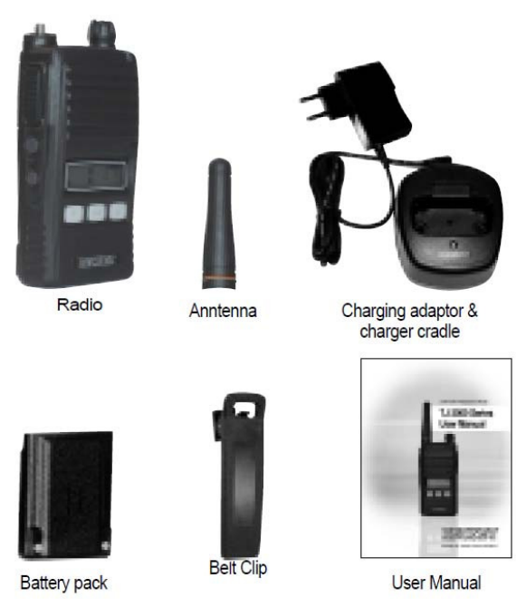
2. Components of XV-100A Radio
* Components could be changed by buyer request.
Figure 2-1) standard components of XV-100A Radio
Replacement Parts
TJA-1800LI Battery - 1800 mAH Lithium ion
TJA-341 Antenna - VHF
TJA-300L Charger - Rapid Rate
TJA-30BC Belt Clip
Optional Accessories
ACC-600TJ3 Vehicular Charger - Single Unit
ACC-6110TJ3 Charger - 6 Unit Gang Charger
TA-836X Speaker Microphone - Standard
TA-850X Speaker Microphone - Heavy Duty
TA-818X Ear Speaker (Discreet Audio Cord) w/Lapel Mic/PTT
TA-819X Ear Speaker (“D” Hook) w/Lapel Mic/PTT
5
TJA-30NC Case - Nylon w/Belt Loop/Swivel
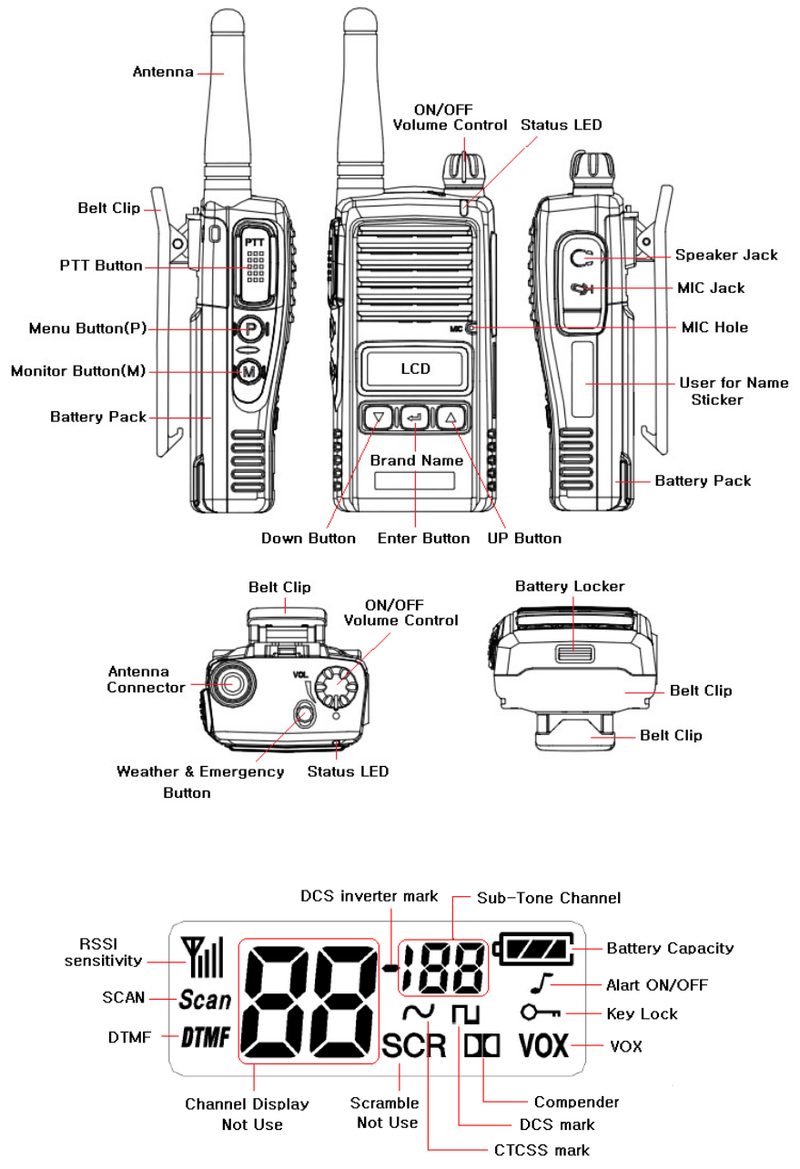
3. Appearance of XV-100A Radio
Figure 3-1) Appearance of XV-100A
6
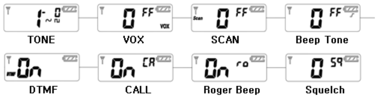
Figure 3-2) XV-100A LCD Indication
4. Basic Operation of XV-100A
Pease read this manual carefully before using XV-100A series Radio.
This manual contains important information about using Radio.
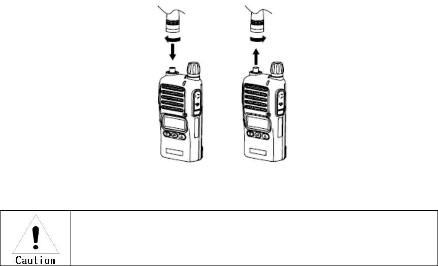
4.1 Installation and Removing the Antenna
To install the antenna, insert the antenna into antenna connector and screw the antenna clockwise.
To remove the antenna, screw the antenna counter clockwise.
Figure 4-1) Installation and Removing the Antenna
When installation of the antenna, giving a strong pressure to the Radio or
pulling the antenna with a strong power from the Radio can make a damage on
the antenna connector, which may cause the Radio to have a critical problem.
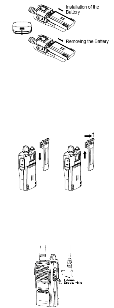
4.2 Installation and Removing the Battery
4.2.1 Installation of the battery
To install battery, slide up the battery towards the top of the radio until battery latch is locked.
4.2.2 Removing the Battery
- Slide the battery latch located on the bottom of radio to the open position as shown in
Figure 4-2.
- The battery is removed by pressing it against and sliding it towards the bottom of the radio
7
Figure 4-2) Installation and Removing the Battery
4.3 Installation and Removing the Belt Clip
- To attach belt clip to radio, align belt clip rails with the grooves in radio and slide the belt clip
onto the mounting rails until it latches into place.
- To remove belt clip from radio, push up on tab of belt clip with flat bladed screwdriver and at
the same time, slide the belt clip towards the top of Radio (Figure4-3).
Figure 4-3) Installation and Removing the Belt Clip
4.4 Accessory connector
Accessory connector is used to connect external speaker/Mic, and headset, etc.
Please close the cover when nothing is connected.
Figure 4-4) Accessory connector

8
5. Charging the Battery
5.1 Safety Notes
1) The radio of XV-100A series receives power from high-performance Li-ion battery
(TJA-1800LI). TJA-1800LI Battery is safe of high performance and highly reliable, and could be
charged very fast.
TJA-1800LI Battery has been designed suitably only for the charger
The charging of the enclosed Radio on the other maker’s charger will cause
a damage on the battery and also, will cause a trouble on the Radio.
2) Please charge the battery before using the radio for best performance and safety.
3) When you charge the battery that is installed in the Radio, please turn off the radio first to charge
the battery.
The continuous rapid discharge (for example, when making a short circuit on
the ‘+’ terminal of battery by a metal substance) may make a fatal defect and
the battery can be exploded. Also, it can cause a fire.
4) Using the correct battery will improve the efficiency and safety.
5.2 The Time of Charging
Low battery voltage will make the radio less coverage and also make the performance worse.
Please charge the battery in case of following:
When you think performance of the radio becomes lower
When the red lamp on RX/TX Led blinks (every 0.5 second) during transmission or
reception
When the battery icon blinks
When “beep” sound is generated while the radio is in use.
5.3 How to Charge
1) Plug the TJA-300L charger into the electricity power outlet.
2) When charging the Radio with the battery installed, please turn off the power of the Radio
and place the Radio on the charger (The charger has a slide slot.).
3) After completion of the charging, the green LED on the charger will light. However, please
continue the charging for 30 more minutes for the complete full charge.
9
status LED indication status LED indication
During charging Red LED lights. Detecting error Red LED is off.
After charging Green LED lights. When charging Green LED lights
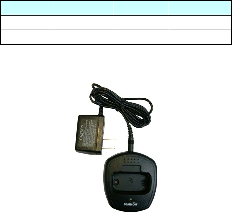
5.4 Charger (TJA-300L)
The TJA-300L charger is designed to charge only the Li-ion battery enclosed in this Radio.
Figure 5-2) TJA-300L Charger
Specifications of TJA-300L Charger :
• Input Voltage : DC85 ~ 250V
• Battery : TJA-1800LI
• Quick Changing Time : In 4Hours and half
• Operation Temperature : 0℃~+50℃
• Size : 75(W)x84.5(D)x36(H)m/m
• Charging Current : 750mA(Fast charging)
10
6. Operating XV-100A RADIO
6.1 On/Off/Volume Control
Turn the knob of Volume Switch clockwise to turn the Radio on and if turning the Switch to the
opposite direction, the Radio is turned off. The audio volume level can be adjusted by turning the
Volume Switch and when adjusting the volume, please refer to the index mark indicated nearby the
Volume knob.
Turns the radio on and off and adjusts audio volume level.
6.2 PTT Button(Push-To-Talk Button)
If pressing the PTT button, the status indication LED lights in red color and the Radio is converted
to transmission mode. If releasing the PTT button, the Radio is converted to reception mode or
standby mode. It is recommended to talk about 5~7cm away from the microphone for using in
better sound quality and for better voice communication
6.3 Menu Button(P, Program Menu Button)
Enter into Menu mode by pressing the Menu button (P) for 2 seconds.
The sequence of menu mode is as follows.
6.4 Monitor Button(M)
The monitor mode is enabled and disabled by pressing the Monitor button (M) on the side.
Normal Mode : During pressing the (M) button for about 2 seconds, it is possible to check the
receiving status.
Continuous Mode : During pressing the (M) button for more than 2 seconds, the Radio will make a
“Beep” tone, which means the monitor function is maintained and if you press the (M) button again,
the monitor function will be released.
6.5 Emergency Button
In case of emergency situation, if you press the Emergency button, a siren sound will be heard
through the speaker in the Radio and the Radio will transmit the emergency signal to the party
through the emergency channel.
11
6.6 Channel Buttons(▼,▲)
Channel Buttons(▼,▲) have 3 functions as shown in following.
Channel buttons(▼,▲) are to change channels.
Channel buttons(▼,▲) are to select menu at menu mode.
Menu(p) + Channel up(▲) are to Channel Lock, Menu(p) + Channel down(▼) are to Channel
unlock
6.7 Accessory Connector
The Accessory Connector is used when using an external speaker microphone or doing PC
programming or making the Cloning or using as a Repeater.
6.8 LED Status
The LED indicates various status' of the radio.
(1) RX - Green color
(2) TX - Red color during PTT
(3) CTCSS, DCS Error - Green color blinking
(4) Low Battery - Red color blinking with beep tone
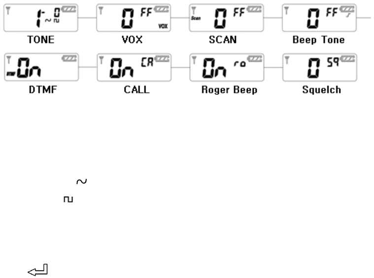
6.7 Function Operation
Enter into Menu mode by pressing the Menu button (P) for 2 seconds.
The sequence of menu mode is as follows.
6.8 CTCSS/DCS/DCS Inverter sub-tone channel selection:
Press Menu (P) button for more than 1 second and the radio will go into function setting mode.
Press UP (▲) or DOWN (▼) button to select Type of Sub-Channel.
CTCSS Sub-Channel : ( )
DCS Sub-Channel : ( )
DCS Inverter Sub-Channel : (▬)
No setting Sub-Channel : (0)
To select CTCSS tone sub-channel, select ( ) by pressing UP (▲ ) or DOWN (▼ ) button, and
press Enter ( ) button.
12
Sub-Tone channel LCD digit will be blinking
Press Up or DOWN to select your desired channel (1~38), and press Enter ( ) button to
confirm it.
To exit from menu, press M button or PTT switch.
Use same method to set up DCS ( ) or DCS Invertor ( ) Sub-Tone Channels
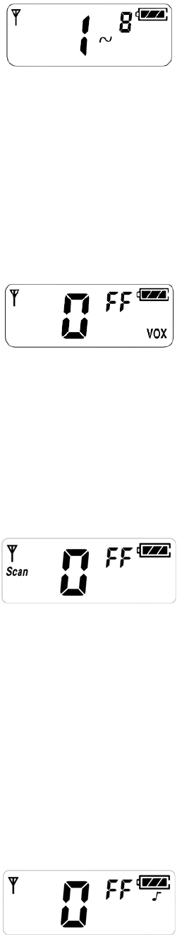
6.8.1 VOX Function On/Off selection:
Press Menu (P) button for more than 1 second and the radio will enter into function setting mode.
Press Menu (P) button again. Then VOX setting Icons will be blinking.
By pressing UP (▲) or DOWN (▼) button, you can select on or off. To exit from menu, press M
button or PTT switch.
6.8.2 Scan On/Off selection:
Press Menu (P) button for more than 1 second and the radio will enter into function setting mode.
Press Menu (P) button 2 times. Radio will go to Scan setting menu mode.
By pressing UP (▲) or DOWN (▼) button, you can select On or Off.
Select on and press Enter ( ) button to confirm Scan On. To exit from menu, Press M button or PTT
switch
If you want to enable Scan function, Press Menu (P) + Enter ( ) at the same time.
Then radio will begin scan. To stop Scan, press Menu (P) button.
( With programming software, a more selective type of scan method can be chosen.)
6.8.3 Beep Tone On/Off selection:
Press Menu (P) button for more than 1 second and the radio will enter into function setting mode.
Press Menu (P) button 3 times. Radio will go to Beep tone on/off setup mode.
13
By Pressing UP (▲) or DOWN (▼) button, set Beep tone on or off. To exit from menu, press M
button or PTT button.
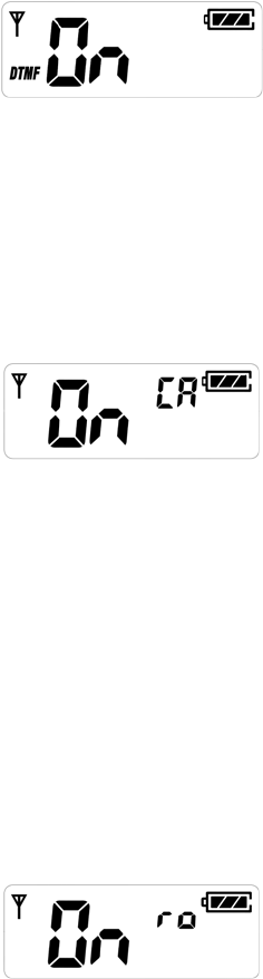
6.8.4 DTMF tone selection:
Press Menu (P) button for more than 1 second and the radio will enter into function setting mode.
Press Menu (P) button 4 times. Radio will go to DTMF setting mode. By pressing UP (▲) or DOWN
(▼) button, and pressing Enter( ) button, you can select 12 different DTMF tones.
To exit from menu, press M button or PTT button.
6.8.5 Call tone selection (10 different call tones):
Press Menu (P) button for more than 1 second and the radio will enter into function setting mode.
Press Menu (P) button 5 times. Radio will go to Call tone selection mode. By pressing UP (▲) or
DOWN (▼) button, and pressing Enter ( ) button, you can select On or Off.
If you select On and press Enter ( ) button, you can select 10 different Call tones by pressing
UP (▲) or DOWN (▼) button. To confirm your setting, please Enter (Icon) button. To exit from
menu, Press M button or PTT button. To enable Call, press Call/Enter( ) button.
Reminder : To receive Call tone, the receiving radio needs to be on the same channel and tone
settings.
6.8.6 Roger Beep On/Off selection:
Press Menu (P) button for more than 1 second and the radio will enter into function setting mode.
Press Menu (P) button 6 times. Radio will go into Roger beep on/off setting mode.
By pressing UP (▲) or DOWN (▼) button will select on or off. To confirm your selection, press
Enter ( ) button.
To exit from menu, press M button or PTT switch.
6.8.7 Squelch level selection:
Press Menu (P) button for more than 1 second and the radio will enter into function setting mode.
Press Menu (P) button 7 times. Radio will goes into Squelch level selection mode.
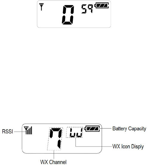
14
By pressing UP (▲) or DOWN (▼), and Enter ( ) button, select your desired Squelch level from 0 to
4. ( 0 means the strongest level and 4 means the weakest level) To exit from menu, press M
button or PTT switch)
6.8.8 Weather On/Off selection:
To enable weather (WX) mode, do a quick press of red button on top of radio.
LCD will display WX mode. Press UP (▲) or DOWN (▼) button to move through WX channels.
To exit from WX mode, press red button again.
** Reminder : When WX mode is enabled, the radio will not transmit or receive talk
transmissions.
When WX is disabled, the radio will revert to it’s previous channel and mode of operation.
6.8.9 EMG (Emergency Alert Tone):
This function allows you to send out distress/locator signals in emergency situation. To activate the
emergency alert tone, press “Red Button” for more than 2 seconds.
The radio will send out a loud alert tone continuously. To deactivate the EMG function, press any
button on the radio.
** Reminder : To receive emergency alert tone, the receiving radio needs to be on the same
channel and tone settings.
1
1